EP1475991A2 - Funkgerät - Google Patents
Funkgerät Download PDFInfo
- Publication number
- EP1475991A2 EP1475991A2 EP04101949A EP04101949A EP1475991A2 EP 1475991 A2 EP1475991 A2 EP 1475991A2 EP 04101949 A EP04101949 A EP 04101949A EP 04101949 A EP04101949 A EP 04101949A EP 1475991 A2 EP1475991 A2 EP 1475991A2
- Authority
- EP
- European Patent Office
- Prior art keywords
- radio
- channel
- transceiver
- loudspeaker
- mounting frame
- Prior art date
- Legal status (The legal status is an assumption and is not a legal conclusion. Google has not performed a legal analysis and makes no representation as to the accuracy of the status listed.)
- Granted
Links
Images


Classifications
-
- H—ELECTRICITY
- H04—ELECTRIC COMMUNICATION TECHNIQUE
- H04B—TRANSMISSION
- H04B1/00—Details of transmission systems, not covered by a single one of groups H04B3/00 - H04B13/00; Details of transmission systems not characterised by the medium used for transmission
- H04B1/06—Receivers
- H04B1/08—Constructional details, e.g. cabinet
- H04B1/082—Constructional details, e.g. cabinet to be used in vehicles
-
- B—PERFORMING OPERATIONS; TRANSPORTING
- B60—VEHICLES IN GENERAL
- B60R—VEHICLES, VEHICLE FITTINGS, OR VEHICLE PARTS, NOT OTHERWISE PROVIDED FOR
- B60R11/00—Arrangements for holding or mounting articles, not otherwise provided for
- B60R11/02—Arrangements for holding or mounting articles, not otherwise provided for for radio sets, television sets, telephones, or the like; Arrangement of controls thereof
- B60R2011/027—Arrangements for holding or mounting articles, not otherwise provided for for radio sets, television sets, telephones, or the like; Arrangement of controls thereof for Din-sized apparatus
Definitions
- the invention relates to a radio device for horizontal installation in a Standard shaft of a motor vehicle, with a built-in radio Speaker whose opening is parallel to the top or bottom of the radio and with a front panel, on the controls are arranged and having a sound outlet opening.
- Radio-based communication is often used for the mobile Communication used.
- these communication means are, for example To understand car radios and radios.
- To these devices To be installed in vehicles are used by the vehicle manufacturers Standard shafts provided. These are often in the center console or embedded in the vehicle ceiling above her. Under a standard shaft For example, in addition to standard shafts according to ISO 7736, too Standard manholes understood according to internal standards of automobile manufacturers.
- radios In commercial vehicles, in addition to a standard shaft for a car radio often another standard slot provided for receiving a radio.
- Such radios are usually designed cuboid and feature via a built-in speaker in its top or bottom wall, which at the same time represent the two largest surfaces of the device.
- Today's radios are often smaller than the standard bay requires.
- the radios have an additional mounting frame on, which in turn fits into the standard shaft. The radio exists in this case from the actual small transceiver and the this receiving mounting frame.
- the additional loudspeaker in the mounting frame can, however, for reasons of space only have a very small diameter. Such is one Small additional speaker prone to damage due to overload. Very unpleasant is also that such a small additional speaker only has a very limited frequency response and in particular low frequencies can transmit poorly, so that the intelligibility on the one hand because of too low output power of the additional Loudspeaker and on the other hand because of the limited frequency response bad is.
- a channel for sound conduction is formed from the speaker to the front of the radio, the at least in its part adjacent to the speaker parallel to Top or bottom of the radio runs and in the sound outlet ends.
- the core of the invention is the departure from the auxiliary speaker and the reuse of the built-in Speaker of the radio also in cases where that Radio is provided with the aforementioned mounting frame. According to the Invention, this is a channel for sound conduction in the radio device, that of the built-in speaker of the radio to the front the device leads and the sound from this front in the room emits.
- inventions are in the subclaims specified.
- the invention is based on a preferred Embodiment, namely a provided with mounting frame Radio device shown and described; however, the invention is but usable for all comparable devices in a standard shaft to be accommodated and a separate speaker which, when installed in a standard shaft behind the vehicle trim radiates.
- a radio 10 has, according to FIG. 1, a bottom wall 11, a top wall 13 ( Figure 2), a front panel 12, a left wall 15 and a right Wall 17 up.
- Figure 2 a top wall 13
- Figure 2 a front panel 12
- left wall 15 a right Wall 17 up.
- the illustrated radio 10 consists of a transceiver 16 with a mounting frame 18 ( Figure 2) surrounding the transceiver and the installation of the relatively small transceiver in the standard slot allows.
- the transceiver 16 may have dimensions that allow it to be inserted directly into the standard slot. In This case contains the elements described below within the transceiver.
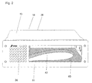
- the mounting frame 18 shown in Fig. 2 has a housing 38 and a Front panel 12 on.
- the housing 38 is made of metal and is cuboidal formed, top wall 13 and bottom wall 11 are its largest Surfaces.
- the outer dimensions of the housing depend on the Standard specifications for the corresponding standard shaft.
- the transceiver 16 also has an upper and a lower wall on, by two side walls, as well as a front and a back wall are connected.
- the top and bottom wall represent the two largest surfaces From the transceiver 16 is when he is in the mounting frame 18 is inserted, for the operator only the front with the Control panel 20 visible.
- On the control panel 20 are a volume control knob 22, a squelch 24, a channel switch 26 and a modulation type changeover switch 28 arranged.
- a socket 30 allows the connection an external microphone that is not shown here. about a display 32 may display status messages to the operator become.
- the transceiver 16 On its underside, the transceiver 16 has a built-in speaker 34.
- the transceiver 16 is inserted into the mounting frame 18,
- the bottom wall of the transceiver of the Sub-wall of the mounting frame spaced by the distance a.
- a channel 42 is formed ( Figure 2).
- the lower boundary of the channel forms the lower wall 11 of the housing 38.
- the channel is laterally in three directions the walls facing him one provided in an insert 40 Recess limited.
- the insert 40 has a flat, cuboid Outer contour with one top and one bottom, as well as four narrow sides. It is dimensioned to fit with its three narrow surfaces the respective walls of the housing 38 and with its lower surface the lower wall of the housing rests. Their thickness is equal to that mentioned Distance a.
- the recess passes through the insert 40 completely and their side surfaces run perpendicular to the bottom of the insert 40.
- the recess has in place, below the speaker in the mounting frame used transceiver, an extension, the about the same as the speaker.
- the recess runs in Fig. 2 on the left edge of the insert 40 and meets the edge of the Corner left front and at the point where one described in more detail below wedge-shaped recess 45 meets the bottom 11 of the housing 38.
- the simple production and processing foamed plastics, in particular foamed polystyrene (e.g., Styropor®).
- the insert 40 is adhesive on the inner surfaces of the housing 38th fixed.
- the channel 42 may be formed, for example, by metal, Cardboard or plastic strip to be limited.
- a molding 44 which is preferably made of the same material like the insert 40.
- the molding 44 is behind the hole field 36 positioned and has essentially the shape of a cuboid, the five sides on the respective inner sides of the walls of the housing 38th of the mounting frame is applied.
- a wedge-shaped recess 45 At the rear of the hole field 36 located Position of the molding 44 is a wedge-shaped recess 45, which opens a space behind the hole field 36, so that sound from this Room can get through the hole field to the outside.
- the wedge-shaped recess is shown in FIG. 1 at its longest, rear Side and bounded on its left side by the molding 44, after through the hole field 36, down through the bottom wall 11 of the Mounting frame and to the right through the left wall of the transceiver 16 limited.
- the space formed by the wedge-shaped recess 45 is a continuation of the channel 42.
- the molding 44 is fixed in position by a metal tab 46, the by three-sided punching and bending up from the lower wall the housing 38 is formed.
- the metal tab 46 is in the middle Hole 50 on.
- a further bore 54 provided through which inserted another screw is attached to the transceiver 16.
- the insert 40 and the molded part 44 additionally serve for vibration-proof fixing of the Transceiver 16.
Landscapes
- Engineering & Computer Science (AREA)
- Computer Networks & Wireless Communication (AREA)
- Signal Processing (AREA)
- Fittings On The Vehicle Exterior For Carrying Loads, And Devices For Holding Or Mounting Articles (AREA)
- Structure Of Receivers (AREA)
- Input Circuits Of Receivers And Coupling Of Receivers And Audio Equipment (AREA)
- Road Signs Or Road Markings (AREA)
Abstract
Description
- Fig. 1
- eine perspektivische Frontalansicht eines Funkgeräts, das aus einem Sendeempfänger und einem Einbaurahmen besteht,
- Fig. 2
- eine der Fig. 1 entsprechende Ansicht eines Einbaurahmens eines erfindungsgemäßen Funkgeräts ohne Sendeempfänger und
- Fig. 3
- eine perspektivische Ansicht schräg von der Seite eines Einbaurahmens ohne Sendeempfänger.
Claims (15)
- Funkgerät zum liegenden Einbau in einen Norm-Schacht eines Kraftfahrzeugs, mit einem in das Funkgerät eingebauten Lautsprecher (34), dessen Öffnung parallel zur Ober- oder Unterseite des Funkgeräts verläuft und mit einer Frontplatte (12), auf der Bedienungselemente (22,24,26,28) angeordnet sind und die eine Schallaustrittsöffnung aufweist,
dadurch gekennzeichnet, dass ein Kanal (42) zur Schallleitung vom Lautsprecher (34) zur Frontseite (12) des Funkgeräts (10) ausgebildet ist, der mindestens in seinem dem Lautsprecher (34) benachbarten Teil parallel zur Ober- oder Unterseite des Funkgeräts verläuft und in der Schallaustrittsöffnung endet. - Funkgerät nach Anspruch 1, dadurch gekennzeichnet, dass der Kanal (42) zumindest teilweise in dem Zwischenraum zwischen dem Lautsprecher (34) und der Unterwand oder der Oberwand des Funkgeräts (10) verläuft.
- Funkgerät nach Anspruch 2, dadurch gekennzeichnet, dass der Kanal (42) hinter der Schallauftrittsöffnung eine keilförmige Gestalt hat und in seinem dem Lautsprecher (34) benachbarten Teil und dem Teil zwischen diesen beiden Abschnitten einen rechteckigen Querschnitt aufweist und in seinem dem Lautsprecher (34) benachbarten Teil etwa die Ausdehnung des Lautsprecher (34) hat.
- Funkgerät nach einem der vorstehenden Ansprüche, dadurch gekennzeichnet, dass der Kanal (42) zumindest teilweise durch eine Einlage (40) aus geschäumtem Kunststoff begrenzt ist.
- Funkgerät nach einem der vorstehenden Ansprüche, dadurch gekennzeichnet, dass der Kanal (42) zumindest teilweise durch die Außenwände (11, 12, 13, 15, 17) des Funkgeräts begrenzt ist.
- Funkgerät nach einem der vorstehenden Ansprüche, dadurch gekennzeichnet, dass der Kanal (42) zumindest teilweise durch Papp-, Kunststoff oder Metallstreifen begrenzt ist.
- Funkgerät nach Anspruch 1, gekennzeichnet durch eine Kompensationsschaltung aufweist, die durch den Weg durch den Kanal (42) entstehende Verzerrungen des Schalls kompensiert.
- Funkgerät nach einem der vorstehenden Ansprüche, dadurch gekennzeichnet, dass es ein CB-Funkgerät ist.
- Funkgerät nach einem der vorstehenden Ansprüche, dadurch gekennzeichnet, dass es zum Einbau in einen Norm-Schacht nach ISO 7736 ausgebildet ist.
- Funkgerät nach einem der vorstehenden Ansprüche, dadurch gekennzeichnet, dass es aus einem Sendeempfänger (16) mit eingebautem Lautsprecher (34) und einem Einbaurahmen (18) gebildet ist.
- Funkgerät nach Anspruch 10, dadurch gekennzeichnet, dass der Sendeempfänger (16) im Einbaurahmen (18) aufgenommen ist und der Kanal (42) im Einbaurahmen (18) gebildet ist.
- Funkgerät nach Anspruch 10 oder 11, dadurch gekennzeichnet, dass sich die Schallauftrittsöffnung im Einbaurahmen befindet, der Kanal in einer Einlage (40) im Einbaurahmen (18) gebildet ist, der Kanal (42) hinter der Schallauftrittsöffnung eine keilförmige, sich von der Öffnung weg verjüngende Gestalt hat und in dem Teil, der dem Lautsprecher (34) des Sendeempfängers benachbart ist, sowie dem Teil zwischen diesen beiden Abschnitten einen rechteckigen Querschnitt aufweist und in seinem dem Sendeempfänger (16) benachbarten Teil etwa die Ausdehnung des Lautsprecher (34) hat.
- Funkgerät nach Anspruch 10, 11 oder 12, dadurch gekennzeichnet, dass der Kanal sich von dem Teil, der dem Lautsprecher (34) des Sendeempfängers benachbart ist, zu der Stelle, in der er eine keilförmige Gestalt hat, verjüngt.
- Funkgerät nach Anspruch 10, 11, 12 oder 13, dadurch gekennzeichnet, dass die Höhe des Kanals dem Abstand zwischen der Unterseite des Sendeempfängers (16) und der Unterwand (11) des Einbaurahmens (18) entspricht.
- Funkgerät nach Anspruch 10, 11, 12 oder 13, dadurch gekennzeichnet, dass die Höhe des Kanals dem Abstand zwischen der Oberseite des Sendeempfängers (16) und der Oberwand (13) des Einbaurahmens (18) entspricht.
Priority Applications (1)
| Application Number | Priority Date | Filing Date | Title |
|---|---|---|---|
| PL04101949T PL1475991T3 (pl) | 2003-05-09 | 2004-05-06 | Urządzenie radiowe |
Applications Claiming Priority (2)
| Application Number | Priority Date | Filing Date | Title |
|---|---|---|---|
| DE20307322U DE20307322U1 (de) | 2003-05-09 | 2003-05-09 | Funkgerät |
| DE20307322U | 2003-05-09 |
Publications (4)
| Publication Number | Publication Date |
|---|---|
| EP1475991A2 true EP1475991A2 (de) | 2004-11-10 |
| EP1475991A8 EP1475991A8 (de) | 2004-12-29 |
| EP1475991A3 EP1475991A3 (de) | 2007-04-18 |
| EP1475991B1 EP1475991B1 (de) | 2008-12-03 |
Family
ID=7981740
Family Applications (1)
| Application Number | Title | Priority Date | Filing Date |
|---|---|---|---|
| EP04101949A Expired - Lifetime EP1475991B1 (de) | 2003-05-09 | 2004-05-06 | Funkgerät |
Country Status (5)
| Country | Link |
|---|---|
| EP (1) | EP1475991B1 (de) |
| AT (1) | ATE416589T1 (de) |
| DE (2) | DE20307322U1 (de) |
| ES (1) | ES2315614T3 (de) |
| PL (1) | PL1475991T3 (de) |
Cited By (3)
| Publication number | Priority date | Publication date | Assignee | Title |
|---|---|---|---|---|
| US8144894B2 (en) | 2008-10-10 | 2012-03-27 | Bose Corporation | Ducting sound |
| US8175279B2 (en) | 2008-10-09 | 2012-05-08 | Bose Corporation | Integrated vehicle audio system |
| US8280073B2 (en) | 2010-03-08 | 2012-10-02 | Bose Corporation | Correcting engine noise cancellation microphone disturbances |
Family Cites Families (6)
| Publication number | Priority date | Publication date | Assignee | Title |
|---|---|---|---|---|
| US2137035A (en) * | 1936-07-15 | 1938-11-15 | Wells Gardner & Company | Radio receiving set |
| JPH01113988A (ja) * | 1987-10-27 | 1989-05-02 | Nissan Motor Co Ltd | 自動車用音響機器 |
| US4846382A (en) * | 1988-01-13 | 1989-07-11 | Nancy E. Foultner | Dash mounting device |
| US5864627A (en) * | 1997-02-14 | 1999-01-26 | Kim; Youngkook | Portable sound system |
| US5974333A (en) * | 1997-07-25 | 1999-10-26 | E-Lead Electronic Co., Ltd. | Automobile acoustic unit having integrated cellular phone capabilities |
| JP2004015149A (ja) * | 2002-06-04 | 2004-01-15 | Kenwood Corp | スピーカの取付けられる筐体の構造 |
-
2003
- 2003-05-09 DE DE20307322U patent/DE20307322U1/de not_active Expired - Lifetime
-
2004
- 2004-05-06 EP EP04101949A patent/EP1475991B1/de not_active Expired - Lifetime
- 2004-05-06 ES ES04101949T patent/ES2315614T3/es not_active Expired - Lifetime
- 2004-05-06 DE DE502004008568T patent/DE502004008568D1/de not_active Expired - Lifetime
- 2004-05-06 AT AT04101949T patent/ATE416589T1/de active
- 2004-05-06 PL PL04101949T patent/PL1475991T3/pl unknown
Cited By (3)
| Publication number | Priority date | Publication date | Assignee | Title |
|---|---|---|---|---|
| US8175279B2 (en) | 2008-10-09 | 2012-05-08 | Bose Corporation | Integrated vehicle audio system |
| US8144894B2 (en) | 2008-10-10 | 2012-03-27 | Bose Corporation | Ducting sound |
| US8280073B2 (en) | 2010-03-08 | 2012-10-02 | Bose Corporation | Correcting engine noise cancellation microphone disturbances |
Also Published As
| Publication number | Publication date |
|---|---|
| ATE416589T1 (de) | 2008-12-15 |
| EP1475991A3 (de) | 2007-04-18 |
| DE502004008568D1 (de) | 2009-01-15 |
| DE20307322U1 (de) | 2003-07-03 |
| EP1475991A8 (de) | 2004-12-29 |
| PL1475991T3 (pl) | 2009-06-30 |
| ES2315614T3 (es) | 2009-04-01 |
| EP1475991B1 (de) | 2008-12-03 |
Similar Documents
| Publication | Publication Date | Title |
|---|---|---|
| DE69734299T2 (de) | Vom Nutzer austauschbarer Deckel für tragbares elektronisches Gerät | |
| DE102010012615B4 (de) | In ein Steuerungsmodulgehäuse eingebaute Schlitzantenne | |
| EP1329085B1 (de) | Kommunikationsendgerät | |
| DE112010005093T5 (de) | Komponentenanordnung | |
| DE112009004704T5 (de) | Gehäuse für eine elektronische Vorrichtung, Vorrichtung mit einem solchen Gehäuse undVerfahren zum Herstellen eines solchen Gehäuses | |
| EP1301012B1 (de) | Mobiles Kommunikationsendgerät mit im Gerätegehäuse angeordnetem Flachlautsprecher und einem weiteren Schallwandler angeordnet zu einem Zwei-Wege-Systems mit dem Flachlautsprecher | |
| DE68908766T2 (de) | Tonanlage, besonders zur stereophonen Tonwiedergabe in einem Fernsehempfangsgerät mit integriertem Tieftonlautsprecher grosser Dimensionen. | |
| DE3424644A1 (de) | Lautsprecher-wandgehaeuse aus harz | |
| DE102016111368A1 (de) | Lautsprecheranordnung in einem Fahrzeug | |
| DE2711849C2 (de) | Halterung von zwei Lautsprechern | |
| EP1240685B1 (de) | Fahrzeugantenne | |
| DE112005002468B4 (de) | Anzeigevorrichtung | |
| DE102012213520A1 (de) | Gehäuse für eine Leiterplatte und Elektrogerät | |
| EP1475991B1 (de) | Funkgerät | |
| DE19605373C2 (de) | Gerät mit einer Anzeigevorrichtung | |
| DE2461322C3 (de) | Lautsprecheranordnung | |
| DE602004003351T2 (de) | Deckel für eine Anzeige eines Kommunikationsgerätes | |
| EP0822693A2 (de) | Freisprecheinrichtung für Telefone in Kraftfahrzeugen | |
| WO2003049493A1 (de) | Displayfenster zur schallabstrahlung in kommunikations- und multimediageräten | |
| DE3002310A1 (de) | Nachrichtentechnisches geraet mit einem quaderfoermigen gehaeuse | |
| DE29724532U1 (de) | Elektronisches Gerät mit Gehäuseergänzung | |
| DE69125512T2 (de) | Tonausrüstung für einen Fernseher | |
| DE20108798U1 (de) | Vorrichtung mit einer multifunktionalen Moduleinheit und einer Mobiltelefon-Basis | |
| DE10014501B4 (de) | Freisprecheinrichtung | |
| DE102004050953B4 (de) | Kraftfahrzeug mit Montageplatz für ein Mikrofon |
Legal Events
| Date | Code | Title | Description |
|---|---|---|---|
| PUAI | Public reference made under article 153(3) epc to a published international application that has entered the european phase |
Free format text: ORIGINAL CODE: 0009012 |
|
| AK | Designated contracting states |
Kind code of ref document: A2 Designated state(s): AT BE BG CH CY CZ DE DK EE ES FI FR GB GR HU IE IT LI LU MC NL PL PT RO SE SI SK TR |
|
| AX | Request for extension of the european patent |
Extension state: AL HR LT LV MK |
|
| RAP1 | Party data changed (applicant data changed or rights of an application transferred) |
Owner name: STABO ELEKTRONIK GMBH |
|
| PUAL | Search report despatched |
Free format text: ORIGINAL CODE: 0009013 |
|
| AK | Designated contracting states |
Kind code of ref document: A3 Designated state(s): AT BE BG CH CY CZ DE DK EE ES FI FR GB GR HU IE IT LI LU MC NL PL PT RO SE SI SK TR |
|
| AX | Request for extension of the european patent |
Extension state: AL HR LT LV MK |
|
| 17P | Request for examination filed |
Effective date: 20070907 |
|
| 17Q | First examination report despatched |
Effective date: 20071029 |
|
| AKX | Designation fees paid |
Designated state(s): AT BE BG CH CY CZ DE DK EE ES FI FR GB GR HU IE IT LI LU MC NL PL PT RO SE SI SK TR |
|
| AXX | Extension fees paid |
Extension state: LT Payment date: 20070907 Extension state: LV Payment date: 20070907 |
|
| GRAP | Despatch of communication of intention to grant a patent |
Free format text: ORIGINAL CODE: EPIDOSNIGR1 |
|
| GRAS | Grant fee paid |
Free format text: ORIGINAL CODE: EPIDOSNIGR3 |
|
| GRAA | (expected) grant |
Free format text: ORIGINAL CODE: 0009210 |
|
| AK | Designated contracting states |
Kind code of ref document: B1 Designated state(s): AT BE BG CH CY CZ DE DK EE ES FI FR GB GR HU IE IT LI LU MC NL PL PT RO SE SI SK TR |
|
| AX | Request for extension of the european patent |
Extension state: LT LV |
|
| REG | Reference to a national code |
Ref country code: GB Ref legal event code: FG4D Free format text: NOT ENGLISH |
|
| REG | Reference to a national code |
Ref country code: RO Ref legal event code: EPE |
|
| REG | Reference to a national code |
Ref country code: CH Ref legal event code: EP |
|
| REG | Reference to a national code |
Ref country code: IE Ref legal event code: FG4D Free format text: LANGUAGE OF EP DOCUMENT: GERMAN |
|
| REF | Corresponds to: |
Ref document number: 502004008568 Country of ref document: DE Date of ref document: 20090115 Kind code of ref document: P |
|
| REG | Reference to a national code |
Ref country code: ES Ref legal event code: FG2A Ref document number: 2315614 Country of ref document: ES Kind code of ref document: T3 |
|
| NLV1 | Nl: lapsed or annulled due to failure to fulfill the requirements of art. 29p and 29m of the patents act | ||
| LTIE | Lt: invalidation of european patent or patent extension |
Effective date: 20081203 |
|
| PG25 | Lapsed in a contracting state [announced via postgrant information from national office to epo] |
Ref country code: SI Free format text: LAPSE BECAUSE OF FAILURE TO SUBMIT A TRANSLATION OF THE DESCRIPTION OR TO PAY THE FEE WITHIN THE PRESCRIBED TIME-LIMIT Effective date: 20081203 Ref country code: FI Free format text: LAPSE BECAUSE OF FAILURE TO SUBMIT A TRANSLATION OF THE DESCRIPTION OR TO PAY THE FEE WITHIN THE PRESCRIBED TIME-LIMIT Effective date: 20081203 Ref country code: NL Free format text: LAPSE BECAUSE OF FAILURE TO SUBMIT A TRANSLATION OF THE DESCRIPTION OR TO PAY THE FEE WITHIN THE PRESCRIBED TIME-LIMIT Effective date: 20081203 |
|
| REG | Reference to a national code |
Ref country code: PL Ref legal event code: T3 |
|
| REG | Reference to a national code |
Ref country code: IE Ref legal event code: FD4D |
|
| PG25 | Lapsed in a contracting state [announced via postgrant information from national office to epo] |
Ref country code: EE Free format text: LAPSE BECAUSE OF FAILURE TO SUBMIT A TRANSLATION OF THE DESCRIPTION OR TO PAY THE FEE WITHIN THE PRESCRIBED TIME-LIMIT Effective date: 20081203 Ref country code: BG Free format text: LAPSE BECAUSE OF FAILURE TO SUBMIT A TRANSLATION OF THE DESCRIPTION OR TO PAY THE FEE WITHIN THE PRESCRIBED TIME-LIMIT Effective date: 20090303 Ref country code: IE Free format text: LAPSE BECAUSE OF FAILURE TO SUBMIT A TRANSLATION OF THE DESCRIPTION OR TO PAY THE FEE WITHIN THE PRESCRIBED TIME-LIMIT Effective date: 20081203 |
|
| PG25 | Lapsed in a contracting state [announced via postgrant information from national office to epo] |
Ref country code: CZ Free format text: LAPSE BECAUSE OF FAILURE TO SUBMIT A TRANSLATION OF THE DESCRIPTION OR TO PAY THE FEE WITHIN THE PRESCRIBED TIME-LIMIT Effective date: 20081203 Ref country code: PT Free format text: LAPSE BECAUSE OF FAILURE TO SUBMIT A TRANSLATION OF THE DESCRIPTION OR TO PAY THE FEE WITHIN THE PRESCRIBED TIME-LIMIT Effective date: 20090504 Ref country code: SE Free format text: LAPSE BECAUSE OF FAILURE TO SUBMIT A TRANSLATION OF THE DESCRIPTION OR TO PAY THE FEE WITHIN THE PRESCRIBED TIME-LIMIT Effective date: 20090303 |
|
| PG25 | Lapsed in a contracting state [announced via postgrant information from national office to epo] |
Ref country code: SK Free format text: LAPSE BECAUSE OF FAILURE TO SUBMIT A TRANSLATION OF THE DESCRIPTION OR TO PAY THE FEE WITHIN THE PRESCRIBED TIME-LIMIT Effective date: 20081203 |
|
| PLBE | No opposition filed within time limit |
Free format text: ORIGINAL CODE: 0009261 |
|
| STAA | Information on the status of an ep patent application or granted ep patent |
Free format text: STATUS: NO OPPOSITION FILED WITHIN TIME LIMIT |
|
| PG25 | Lapsed in a contracting state [announced via postgrant information from national office to epo] |
Ref country code: DK Free format text: LAPSE BECAUSE OF FAILURE TO SUBMIT A TRANSLATION OF THE DESCRIPTION OR TO PAY THE FEE WITHIN THE PRESCRIBED TIME-LIMIT Effective date: 20081203 |
|
| 26N | No opposition filed |
Effective date: 20090904 |
|
| PG25 | Lapsed in a contracting state [announced via postgrant information from national office to epo] |
Ref country code: MC Free format text: LAPSE BECAUSE OF NON-PAYMENT OF DUE FEES Effective date: 20090531 |
|
| REG | Reference to a national code |
Ref country code: CH Ref legal event code: PL |
|
| PG25 | Lapsed in a contracting state [announced via postgrant information from national office to epo] |
Ref country code: LI Free format text: LAPSE BECAUSE OF NON-PAYMENT OF DUE FEES Effective date: 20090531 Ref country code: CH Free format text: LAPSE BECAUSE OF NON-PAYMENT OF DUE FEES Effective date: 20090531 |
|
| REG | Reference to a national code |
Ref country code: CH Ref legal event code: AEN Free format text: DAS PATENT IST AUFGRUND DES WEITERBEHANDLUNGSANTRAGS VOM 01.02.2010 REAKTIVIERT WORDEN. |
|
| PGRI | Patent reinstated in contracting state [announced from national office to epo] |
Ref country code: CH Effective date: 20100201 |
|
| PG25 | Lapsed in a contracting state [announced via postgrant information from national office to epo] |
Ref country code: GR Free format text: LAPSE BECAUSE OF FAILURE TO SUBMIT A TRANSLATION OF THE DESCRIPTION OR TO PAY THE FEE WITHIN THE PRESCRIBED TIME-LIMIT Effective date: 20090304 |
|
| PG25 | Lapsed in a contracting state [announced via postgrant information from national office to epo] |
Ref country code: LU Free format text: LAPSE BECAUSE OF NON-PAYMENT OF DUE FEES Effective date: 20090506 |
|
| PG25 | Lapsed in a contracting state [announced via postgrant information from national office to epo] |
Ref country code: HU Free format text: LAPSE BECAUSE OF FAILURE TO SUBMIT A TRANSLATION OF THE DESCRIPTION OR TO PAY THE FEE WITHIN THE PRESCRIBED TIME-LIMIT Effective date: 20090604 |
|
| PG25 | Lapsed in a contracting state [announced via postgrant information from national office to epo] |
Ref country code: CY Free format text: LAPSE BECAUSE OF FAILURE TO SUBMIT A TRANSLATION OF THE DESCRIPTION OR TO PAY THE FEE WITHIN THE PRESCRIBED TIME-LIMIT Effective date: 20081203 |
|
| PGFP | Annual fee paid to national office [announced via postgrant information from national office to epo] |
Ref country code: TR Payment date: 20130503 Year of fee payment: 10 Ref country code: RO Payment date: 20130429 Year of fee payment: 10 |
|
| PG25 | Lapsed in a contracting state [announced via postgrant information from national office to epo] |
Ref country code: RO Free format text: LAPSE BECAUSE OF NON-PAYMENT OF DUE FEES Effective date: 20140506 |
|
| REG | Reference to a national code |
Ref country code: FR Ref legal event code: PLFP Year of fee payment: 13 |
|
| REG | Reference to a national code |
Ref country code: FR Ref legal event code: PLFP Year of fee payment: 14 |
|
| PG25 | Lapsed in a contracting state [announced via postgrant information from national office to epo] |
Ref country code: TR Free format text: LAPSE BECAUSE OF NON-PAYMENT OF DUE FEES Effective date: 20140506 |
|
| REG | Reference to a national code |
Ref country code: FR Ref legal event code: PLFP Year of fee payment: 15 |
|
| PGFP | Annual fee paid to national office [announced via postgrant information from national office to epo] |
Ref country code: CH Payment date: 20200522 Year of fee payment: 17 |
|
| PGFP | Annual fee paid to national office [announced via postgrant information from national office to epo] |
Ref country code: GB Payment date: 20200522 Year of fee payment: 17 |
|
| REG | Reference to a national code |
Ref country code: CH Ref legal event code: PL |
|
| GBPC | Gb: european patent ceased through non-payment of renewal fee |
Effective date: 20210506 |
|
| PG25 | Lapsed in a contracting state [announced via postgrant information from national office to epo] |
Ref country code: CH Free format text: LAPSE BECAUSE OF NON-PAYMENT OF DUE FEES Effective date: 20210531 Ref country code: LI Free format text: LAPSE BECAUSE OF NON-PAYMENT OF DUE FEES Effective date: 20210531 |
|
| PG25 | Lapsed in a contracting state [announced via postgrant information from national office to epo] |
Ref country code: GB Free format text: LAPSE BECAUSE OF NON-PAYMENT OF DUE FEES Effective date: 20210506 |
|
| PGFP | Annual fee paid to national office [announced via postgrant information from national office to epo] |
Ref country code: PL Payment date: 20230329 Year of fee payment: 20 |
|
| PGFP | Annual fee paid to national office [announced via postgrant information from national office to epo] |
Ref country code: IT Payment date: 20230531 Year of fee payment: 20 Ref country code: FR Payment date: 20230517 Year of fee payment: 20 Ref country code: ES Payment date: 20230621 Year of fee payment: 20 Ref country code: DE Payment date: 20230608 Year of fee payment: 20 |
|
| PGFP | Annual fee paid to national office [announced via postgrant information from national office to epo] |
Ref country code: AT Payment date: 20230516 Year of fee payment: 20 |
|
| PGFP | Annual fee paid to national office [announced via postgrant information from national office to epo] |
Ref country code: BE Payment date: 20230517 Year of fee payment: 20 |
|
| REG | Reference to a national code |
Ref country code: DE Ref legal event code: R071 Ref document number: 502004008568 Country of ref document: DE |
|
| REG | Reference to a national code |
Ref country code: ES Ref legal event code: FD2A Effective date: 20240524 |
|
| REG | Reference to a national code |
Ref country code: BE Ref legal event code: MK Effective date: 20240506 |
|
| REG | Reference to a national code |
Ref country code: AT Ref legal event code: MK07 Ref document number: 416589 Country of ref document: AT Kind code of ref document: T Effective date: 20240506 |
|
| PG25 | Lapsed in a contracting state [announced via postgrant information from national office to epo] |
Ref country code: ES Free format text: LAPSE BECAUSE OF EXPIRATION OF PROTECTION Effective date: 20240507 |
|
| PG25 | Lapsed in a contracting state [announced via postgrant information from national office to epo] |
Ref country code: ES Free format text: LAPSE BECAUSE OF EXPIRATION OF PROTECTION Effective date: 20240507 |