EP1475876A1 - Ladegerät für einen Akkupack, sowie Anordnung aus Ladegerät und Akkupack - Google Patents
Ladegerät für einen Akkupack, sowie Anordnung aus Ladegerät und Akkupack Download PDFInfo
- Publication number
- EP1475876A1 EP1475876A1 EP03010066A EP03010066A EP1475876A1 EP 1475876 A1 EP1475876 A1 EP 1475876A1 EP 03010066 A EP03010066 A EP 03010066A EP 03010066 A EP03010066 A EP 03010066A EP 1475876 A1 EP1475876 A1 EP 1475876A1
- Authority
- EP
- European Patent Office
- Prior art keywords
- charger
- battery pack
- air
- blower device
- cooling
- Prior art date
- Legal status (The legal status is an assumption and is not a legal conclusion. Google has not performed a legal analysis and makes no representation as to the accuracy of the status listed.)
- Granted
Links
Images


Classifications
-
- H—ELECTRICITY
- H02—GENERATION; CONVERSION OR DISTRIBUTION OF ELECTRIC POWER
- H02J—ELECTRIC POWER NETWORKS; CIRCUIT ARRANGEMENTS OR SYSTEMS FOR SUPPLYING OR DISTRIBUTING ELECTRIC POWER; SYSTEMS FOR STORING ELECTRIC ENERGY
- H02J7/00—Circuit arrangements for charging or discharging batteries or for supplying loads from batteries
- H02J7/70—Circuit arrangements for charging or discharging batteries or for supplying loads from batteries characterised by the mechanical construction
Definitions
- the present invention relates to a charger for a Battery pack, in particular a Elektrohandwerkmaschinegerats, with a blower device for cooling the battery pack while of the shop.
- the present invention is based on the object Charger of the type mentioned in terms of a to further improve effective cooling.
- the Blower device so oriented and arranged that they both for cooling the battery pack and for cooling electronic components inside the charger.
- the cooling air through the Inflow sucked in, by a wall of the Battery packs can be covered or cushioned. If the Battery pack in a manner to be described in more detail also of cooling air can be flowed through and in the area of Inlet opening of the charger an outflow opening has, so in the charger cooling air, the previously was sucked through the battery pack, into the interior of the Chargers are sucked in and there electronic Cool components.
- the inflow opening and to be cooled electronic components of the charger as well as the after Outside fan blower means are arranged so that air sucked in by said inflow opening Operation of the blower device and the charger on their Way to blower device to be cooled electronic Components applied, swept or flows around, so that they are cooled.
- thermally connected cooling plate which is arranged so that it from Air flow is effectively applied.
- the air flow is guided along the cooling plate.
- a cooling plate proves to be especially advantageous if this thermally with a Power transistor or another strong heat developing component is connected.
- the power transistor has a good thermal conductivity Glue or otherwise attached to the heat sink.
- the blower device is arranged so that she promotes into the convection area, so over the Convection area to the outside of the charger promotes.
- the blower device may in such case, depending on the strength, located in the convection area during operation of the charger assisting convective flow or even assist overlap. It can also provide the convective cooling air flow almost completely suppress air by only passing through promoted the fan device in the convection area and from there over the upper and / or lower opening is blown outside the charger.
- the inflow and outflow openings in particular the Air inlet and outlet openings of the Convection areas are preferably at an upper one and / or lower housing wall, not on the other hand Side walls of the charger provided. This opens the ability to put the charger in one of his Transverse dimension substantially corresponding area in a shelf between other objects saves space to arrange without the cooling effect is reduced. As a result of the usually in operating position up
- the charger's opening slot is the top anyway always accessible. Since usually at the Ground side stand elements are provided, can also be air from below into the convection areas.
- the invention further relates to an arrangement of a charger according to the invention and a battery pack, the characterized in that the battery pack in alignment with or communicating with the via a flow path Air inlet opening of the charger a Heilausströmo réelle and at a location spaced therefrom Air inlet has, so that during operation of the Blower device of the charger cooling air first over the Heileinströmö réelle sucked into the battery pack and the Cooling the battery cells is used and then continue over the air outlet opening of the battery pack and the Air inlet opening of the charger in the interior of the charger Charger sucked and there for cooling electronic Components of the charger is used and over Blower out of the charger back out becomes.
- the air inflow opening of the battery pack is preferably on the upper housing wall in loading mode and / or on the from the air outlet opening of the battery pack provided on the opposite side, so that the battery cells inside the battery pack preferably over its entire Long acted upon by sucked cooling air.
- the air outlet opening of the battery pack is preferably in a wall of the battery pack provided substantially transverse to the depth extension of a contact shaft of Battery pack runs, with this in a plug-in slot the charger can be used.
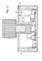
- Figures 1 and 2 show in longitudinal or A cross-sectional view a total of the reference numeral 2 designated inventive charger with a in the Insert slot 4 of the charger 2 inserted battery pack 6.
- the charger 2 comprises a housing lower shell 8 and a housing upper shell 10, which latter the Plug-in shaft 4 limited.
- the battery pack 6 is off an upper and lower housing half shell 12, 14 is formed, wherein the lower housing half shell 12 the contact shaft 16 of the battery pack 6 forms.
- a Blower 24 which is attached to the lower shell 8 and so oriented that it takes air from the interior 26 of the Charger to the outside of the charger promotes.
- the Blower 24 promotes the air through a first Convection region 28 to the outside.
- the first Convection region 28 is bounded by a side wall 30 of the housing upper shell and a cooling plate 32, which in substantially parallel to the side wall 30 extends.
- In the lower shell 8 are Heileintrittso réelleen 34 and in the Upper shell 10 Heilausstromo réelleen 36 formed. in the Otherwise, the first convection region 28 is essentially sealed against the interior 26 of the charger.
- the Blower thus sucks air from the interior 26 of the Charger in the first convection area 28 and through the openings 34, 36 to the outside of the charger 2.
- the mentioned cooling plate 32 is thermally conductive with a Power transistor 38 (see Figure 3) connected. It will cooled by a convective air flow, which is adjusts when the cooling plate 32, the air inside the heated first convection space 28. If in addition the Promotes blower 24, so this is convective Air flow supported depending on the blower strength or layered; In any case, a stream of air along the Cooling plate 32 passes and thus effectively cools the Power transistor 38.
- a second one Convection region 40 is formed, which also by a Cooling plate 42 is limited to the inside of the housing. Again, lower air inlet openings 44 and upper Air outlet openings 46 are provided.
- the cooling plate 42 is in a corresponding manner coupled with another Power transistor 48. Immediately to the transistor 48 Subsequently, an air inlet opening 50 in the Cooling plate 42 is provided, which has a flow resistance having approximately one of the plurality of air outlets 46 corresponds.
- This Air inflow opening 52 is in a designated Use upper wall of the charger 2 provided, and although in an area 53 in which a wall of the battery pack 6 adjacent to the charger 2. This is from FIG. 1 seen. It can be seen that in the inserted state of the Battery packs 6, a wall 54 of the lower housing half shell 12 of the battery pack 6, the Lufteinstromo réelle 52 overlaps. Immediately the Heileinströmo réelle 52 is opposite a Heilausströmo réelle 56 in the wall 54 of the battery pack 6 trained.
- the battery pack 6 in the upper Housing half shell 14 air inlet openings 58 on.
- the Air flow through the battery pack 6 is through in Figure 1 shown arrows visible.
- the Blower 24 is fresh Kuhlluft through the Air inlet openings 58 are sucked into the battery pack 6 and sweeps past the battery cells and cools them. Further the air passes through the air outlet 56 of the Battery packs and the air inlet opening 52 in the interior 26th of the charger 2 and acts there to be cooled electronic components 20 on their way to Blower device 24.
- the fan 24 is therefore both for cooling the Battery cells of the battery pack 6 and for cooling electronic components of the charger used. It proves to be beneficial that fresh cooling air first the battery cells of the battery pack 6 cools where the strongest Heat development takes place, and the cooling air then to Cooling electronic components is used.
Landscapes
- Secondary Cells (AREA)
- Engineering & Computer Science (AREA)
- Power Engineering (AREA)
- Charge And Discharge Circuits For Batteries Or The Like (AREA)
Abstract
Description
- Figur 1
- eine Längsschnittansicht durch ein erfindungsgemäßes Ladegerat mit eingestecktem Akkupack;
- Figur 2
- eine Querschnittansicht gesehen in Richtung der Pfeile II-II in Figur 1;
- Figur 3
- eine perspektivische Ansicht einer Unterschale des Ladegeräts nach Figur 1 mit elektronischen Komponenten und
- Figur 4
- eine perspektivische Ansicht der Unterschale nach Figur 3 mit teilweise dargestellter Oberschale.
Claims (15)
- Ladegerät (2) für einen Akkupack (6), insbesondere eines Elektrohandwerkzeuggerats, mit einer Gebläseeinrichtung (24) zur Kühlung des Akkupacks (6)während des Ladens, dadurch gekennzeichnet, dass die Gebläseeinrichtung (24) so angeordnet ist, dass sie Luft von innen (26) nach außerhalb des Ladegeräts (2) fördert und dass in einer Gehäusewandung angrenzend an den in das Ladegerät (2) eingesetzten Akkupack (6) eine Einströmöffnung (52) vorgesehen ist, und dass im Betrieb elektronische Komponenten (20) des Ladegeräts von durch diese Einströmoffnung (52) in das Ladegerät eingesogener Luft auf deren Weg zur Gebläseeinrichtung (24) beaufschlagbar und kühlbar sind.
- Ladegerät nach Anspruch 1, dadurch gekennzeichnet, dass im Inneren (26) des Ladegeräts ein mit einer elektronischen Komponente (20) thermisch verbundenes Kühlblech (32) vorgesehen ist, welches so angeordnet ist, dass es vom Luftstrom beaufschlagt ist.
- Ladegerät nach Anspruch 1 oder 2, dadurch gekennzeichnet, dass im Inneren (26) des Ladegeräts ein Konvektionsbereich (28) ausgebildet ist, der über untere Lufteinrittsoffnungen (34) und obere Luftausströmöffnungen (36) konvektiv durchströmbar ist.
- Ladegerät nach Anspruch 3, dadurch gekennzeichnet, dass der Konvektionsbereich (28) von einem mit einer elektronischen Komponente (38) thermisch verbundenen Kühlblech (32) begrenzt ist.
- Ladegerät nach Anspruch 3 oder 4, dadurch gekennzeichnet, dass der Konvektionsbereich (28) einerseits außen von einer Gehausewandung (30) des Ladegeräts (2) und andererseits innen von dem Kuhlblech (32) begrenzt ist.
- Ladegerät nach einem oder mehreren der vorstehenden Anspruche, dadurch gekennzeichnet, dass die Gebläseeinrichtung (24) in den Konvektionsbereich (28) fördert.
- Ladegerät nach einem oder mehreren der vorstehenden Ansprüche, dadurch gekennzeichnet, dass im Inneren (26) des Ladegeräts (2) mehrere, vorzugsweise zwei Konvektionsbereiche (28, 40) ausgebildet sind.
- Ladegerät nach einem oder mehreren der vorstehenden Ansprüche, dadurch gekennzeichnet, dass ein Konvektionsbereich (40), der nicht auf der Abstromseite der Gebläseeinrichtung (24) vorgesehen ist, über eine Verbindungsöffnung (50) mit dem Inneren (26) des Ladegeräts verbunden sind.
- Ladegerat nach einem oder mehreren der vorstehenden Anspruche, dadurch gekennzeichnet, dass mit Ausnahme von der gegebenenfalls vorgesehenen Verbindungsöffnung (50) das Innere (26) des Ladegeräts dicht ist und die Luftströmung im wesentlichen nur über die Einstromöffnung (52) in das Ladegerät hinein und über die Gebläseeinrichtung (24) aus dem Ladegerät heraus erfolgt.
- Ladegerät nach einem oder mehreren der vorstehenden Anspruche, dadurch gekennzeichnet, dass Offnungen (34, 36, 44, 46, 52) nur an einer oberen und/oder unteren Gehausewandung vorgesehen sind.
- Ladegerat nach einem oder mehreren der vorstehenden Ansprüche, dadurch gekennzeichnet, dass es eine Unterschale (8) und eine Oberschale (10) als gehausebildende Komponenten aufweist, von denen eine einen Konvektionsbereich (28, 40) zumindest abschnittsweise begrenzt.
- Ladegerät nach einem oder mehreren der vorstehenden Ansprüche, dadurch gekennzeichnet, dass es eine Unterschale (8) und eine Oberschale (10) als gehausebildende Komponenten aufweist und die Unterschale (8) eine Leiterplatte (10) mit elektronischen Komponenten hält.
- Anordnung aus einem Ladegerat (2) nach einem oder mehreren der vorstehenden Anspruche und einem Akkupack (6), dadurch gekennzeichnet, dass der Akkupack (6) fluchtend mit oder über einen Stromungspfad kommunizierend mit der Lufteinströmöffnung (52) des Ladegeräts (2) eine Luftausströmoffnung (56) und an hiervon beabstandeter Stelle eine Lufteinströmöffnung (58) aufweist, so dass im Betrieb der Gebläseeinrichtung (24) des Ladegeräts (2) Kühlluft zunächst über die Lufteinströmoffnung (58) in den Akkupack (6) eingesogen und zur Kühlung der Akkuzellen verwendet wird und dann weiter über die Luftausströmöffnung (56) des Akkupacks (6) und die Lufteinströmöffnung (52) des Ladegeräts (2) in das Innere (26) des Ladegeräts (2) hineinströmt und dort zur Kühlung elektronischer Komponenten (20, 38) des Ladegeräts (2) verwendet wird und über die Gebläseeinrichtung (24) aus dem Ladegerät (2) wieder hinaus gefördert wird.
- Anordnung nach Anspruch 13, dadurch gekennzeichnet, dass die Lufteinströmöffnung (58) des Akkupacks (6) an der im Ladebetrieb oberen Gehäusewandung und /oder auf der von der Luftausstromoffnung (56) gegenüberliegenden Seite des Akkupacks vorgesehen ist.
- Anordnung nach Anspruch 13 oder 14, dadurch gekennzeichnet, dass die Luftausströmöffnung (56) des Akkupacks (6) in einer Wandung (54) des Akkupacks vorgesehen ist, die im wesentlichen quer zur Tiefenerstreckung des Kontaktschafts (16) des Akkupacks verläuft.
Priority Applications (3)
| Application Number | Priority Date | Filing Date | Title |
|---|---|---|---|
| AT03010066T ATE494652T1 (de) | 2003-05-03 | 2003-05-03 | Ladegerät für einen akkupack, sowie anordnung aus ladegerät und akkupack |
| EP03010066A EP1475876B1 (de) | 2003-05-03 | 2003-05-03 | Ladegerät für einen Akkupack, sowie Anordnung aus Ladegerät und Akkupack |
| DE50313392T DE50313392D1 (de) | 2003-05-03 | 2003-05-03 | Ladegerät für einen Akkupack, sowie Anordnung aus Ladegerät und Akkupack |
Applications Claiming Priority (1)
| Application Number | Priority Date | Filing Date | Title |
|---|---|---|---|
| EP03010066A EP1475876B1 (de) | 2003-05-03 | 2003-05-03 | Ladegerät für einen Akkupack, sowie Anordnung aus Ladegerät und Akkupack |
Publications (2)
| Publication Number | Publication Date |
|---|---|
| EP1475876A1 true EP1475876A1 (de) | 2004-11-10 |
| EP1475876B1 EP1475876B1 (de) | 2011-01-05 |
Family
ID=32981803
Family Applications (1)
| Application Number | Title | Priority Date | Filing Date |
|---|---|---|---|
| EP03010066A Expired - Lifetime EP1475876B1 (de) | 2003-05-03 | 2003-05-03 | Ladegerät für einen Akkupack, sowie Anordnung aus Ladegerät und Akkupack |
Country Status (3)
| Country | Link |
|---|---|
| EP (1) | EP1475876B1 (de) |
| AT (1) | ATE494652T1 (de) |
| DE (1) | DE50313392D1 (de) |
Cited By (6)
| Publication number | Priority date | Publication date | Assignee | Title |
|---|---|---|---|---|
| EP2819266A1 (de) * | 2013-06-25 | 2014-12-31 | Makita Corporation | Ladegerät |
| CN106058388A (zh) * | 2015-04-10 | 2016-10-26 | 丰田自动车株式会社 | 车载二次电池的冷却系统 |
| WO2018210764A1 (de) * | 2017-05-15 | 2018-11-22 | Hoppecke Batterien Gmbh & Co. Kg | Mobiler container zum laden von batterien |
| US10827655B2 (en) | 2017-06-26 | 2020-11-03 | Milwaukee Electric Tool Corporation | Battery charger |
| EP4016783A1 (de) * | 2020-12-15 | 2022-06-22 | Andreas Stihl AG & Co. KG | Ladegerät mit ladeelektronikeinheit und kühlluftführungsstruktur |
| US11670808B2 (en) | 2019-12-03 | 2023-06-06 | Milwaukee Electric Tool Corporation | Charger and charger system |
Families Citing this family (1)
| Publication number | Priority date | Publication date | Assignee | Title |
|---|---|---|---|---|
| WO2023283429A1 (en) | 2021-07-08 | 2023-01-12 | Milwaukee Electric Tool Corporation | Power tool system |
Citations (7)
| Publication number | Priority date | Publication date | Assignee | Title |
|---|---|---|---|---|
| JPH08185898A (ja) * | 1994-12-28 | 1996-07-16 | Yamaha Motor Co Ltd | 2次電池の冷却装置 |
| JPH11122829A (ja) * | 1997-10-15 | 1999-04-30 | Yamaha Motor Co Ltd | バッテリーの充電装置 |
| EP0920105A2 (de) * | 1997-11-25 | 1999-06-02 | Matsushita Electric Works, Ltd. | Lader |
| EP0940864A2 (de) * | 1998-03-05 | 1999-09-08 | Black & Decker Inc. | Kühlsystem für Batteriesatz |
| EP0978923A2 (de) * | 1998-07-02 | 2000-02-09 | Makita Corporation | Elektrisches Werkzeugladesystem, welches Batterie rekonditionierung und Batteriekapazitätsdaten Updatefunktionen verwendet |
| US6027535A (en) * | 1996-02-27 | 2000-02-22 | Metabowerke Gmbh & Co. | Battery charger for power tools |
| JP2002084604A (ja) * | 2000-09-07 | 2002-03-22 | Sanyo Electric Co Ltd | 電気自動車用バッテリシステム |
Family Cites Families (1)
| Publication number | Priority date | Publication date | Assignee | Title |
|---|---|---|---|---|
| EP1381134B1 (de) * | 2002-07-12 | 2011-11-16 | HILTI Aktiengesellschaft | Akkubatterie-Ladestation |
-
2003
- 2003-05-03 EP EP03010066A patent/EP1475876B1/de not_active Expired - Lifetime
- 2003-05-03 DE DE50313392T patent/DE50313392D1/de not_active Expired - Lifetime
- 2003-05-03 AT AT03010066T patent/ATE494652T1/de active
Patent Citations (7)
| Publication number | Priority date | Publication date | Assignee | Title |
|---|---|---|---|---|
| JPH08185898A (ja) * | 1994-12-28 | 1996-07-16 | Yamaha Motor Co Ltd | 2次電池の冷却装置 |
| US6027535A (en) * | 1996-02-27 | 2000-02-22 | Metabowerke Gmbh & Co. | Battery charger for power tools |
| JPH11122829A (ja) * | 1997-10-15 | 1999-04-30 | Yamaha Motor Co Ltd | バッテリーの充電装置 |
| EP0920105A2 (de) * | 1997-11-25 | 1999-06-02 | Matsushita Electric Works, Ltd. | Lader |
| EP0940864A2 (de) * | 1998-03-05 | 1999-09-08 | Black & Decker Inc. | Kühlsystem für Batteriesatz |
| EP0978923A2 (de) * | 1998-07-02 | 2000-02-09 | Makita Corporation | Elektrisches Werkzeugladesystem, welches Batterie rekonditionierung und Batteriekapazitätsdaten Updatefunktionen verwendet |
| JP2002084604A (ja) * | 2000-09-07 | 2002-03-22 | Sanyo Electric Co Ltd | 電気自動車用バッテリシステム |
Non-Patent Citations (3)
| Title |
|---|
| PATENT ABSTRACTS OF JAPAN vol. 1996, no. 11 29 November 1996 (1996-11-29) * |
| PATENT ABSTRACTS OF JAPAN vol. 1999, no. 09 30 July 1999 (1999-07-30) * |
| PATENT ABSTRACTS OF JAPAN vol. 2002, no. 07 3 July 2002 (2002-07-03) * |
Cited By (14)
| Publication number | Priority date | Publication date | Assignee | Title |
|---|---|---|---|---|
| EP2819266A1 (de) * | 2013-06-25 | 2014-12-31 | Makita Corporation | Ladegerät |
| US9728984B2 (en) | 2013-06-25 | 2017-08-08 | Makita Corporation | Using ribs in charger to dissipate heat generated by charging circuit |
| CN106058388A (zh) * | 2015-04-10 | 2016-10-26 | 丰田自动车株式会社 | 车载二次电池的冷却系统 |
| CN106058388B (zh) * | 2015-04-10 | 2019-02-15 | 丰田自动车株式会社 | 车载二次电池的冷却系统 |
| WO2018210764A1 (de) * | 2017-05-15 | 2018-11-22 | Hoppecke Batterien Gmbh & Co. Kg | Mobiler container zum laden von batterien |
| CN110692148A (zh) * | 2017-05-15 | 2020-01-14 | 荷贝克先进电池技术有限责任公司 | 电池充电用移动容器 |
| US10827655B2 (en) | 2017-06-26 | 2020-11-03 | Milwaukee Electric Tool Corporation | Battery charger |
| US11839066B2 (en) | 2017-06-26 | 2023-12-05 | Milwaukee Electric Tool Corporation | Battery charger |
| US12262516B2 (en) | 2017-06-26 | 2025-03-25 | Milwaukee Electric Tool Corporation | Battery pack, charger and disconnect system |
| US11670808B2 (en) | 2019-12-03 | 2023-06-06 | Milwaukee Electric Tool Corporation | Charger and charger system |
| US12015130B2 (en) | 2019-12-03 | 2024-06-18 | Milwaukee Electric Tool Corporation | Charger and charger system |
| US12412936B2 (en) | 2019-12-03 | 2025-09-09 | Milwaukee Electric Tool Corporation | Battery pack and charger system |
| EP4016783A1 (de) * | 2020-12-15 | 2022-06-22 | Andreas Stihl AG & Co. KG | Ladegerät mit ladeelektronikeinheit und kühlluftführungsstruktur |
| US12196445B2 (en) | 2020-12-15 | 2025-01-14 | Andreas Stihl Ag & Co. Kg | Charger having a charging electronics unit and a cooling-air-guiding structure |
Also Published As
| Publication number | Publication date |
|---|---|
| ATE494652T1 (de) | 2011-01-15 |
| DE50313392D1 (de) | 2011-02-17 |
| EP1475876B1 (de) | 2011-01-05 |
Similar Documents
| Publication | Publication Date | Title |
|---|---|---|
| EP1844637B1 (de) | Anordnung zur kühlung von elektronischen moduleinheiten in geräte -und netzwekschränken | |
| DE60006630T2 (de) | Verbinder | |
| DE102007024898B4 (de) | Fahrzeugluftkanal | |
| DE10128307B4 (de) | Klimaanlage | |
| DE69839296T2 (de) | Lader | |
| DE202007018397U1 (de) | Thermoelektrische Temperiervorrichtung | |
| DE112016001980T5 (de) | Hausgerätvorrichtung | |
| DE4440044C2 (de) | Klimagerät | |
| EP1475876A1 (de) | Ladegerät für einen Akkupack, sowie Anordnung aus Ladegerät und Akkupack | |
| DE19710622A1 (de) | Kreiselgebläse mit integrierter Steuereinheit, insbesondere für Kraftfahrzeuge | |
| DE19920061C1 (de) | Heizungs- oder Klimaanlage für eine Fahrgastzelle eines Kraftfahrzeugs | |
| DE102005007545B4 (de) | Vorrichtung und Verfahren zur Kühlung einer Elektronik | |
| WO2005087525A1 (de) | Vorrichtung zur belüftung und kühlung eines kraftfahrzeuginnenraumes | |
| DE102004020147B4 (de) | Anordnung umfassend ein Ladegerät und einen Akkupack | |
| DE102009057129A1 (de) | Belüftungsvorrichtung für Komponenten eines Elektronik- oder Computerschranks | |
| DE102012007707B4 (de) | Kühlgerät für die Schaltschrankkühlung | |
| DE102006055216A1 (de) | Heizeinrichtung für Dieselkraftstoff und beheizbares Dieselfiltersystem | |
| EP0650411A1 (de) | Vorrichtung zum thermischen trocknen von materialbahnen, -bögen od.dgl. | |
| DE3044135A1 (de) | Luft-luft-waermetauscher | |
| DE19804905C2 (de) | Schaltschrank | |
| DE102008051507B4 (de) | Bekleidungstrockner | |
| EP2991466A2 (de) | Temperiereinrichtung zum regulieren der temperatur in einem raum und schaltschrank mit einer derartigen temperiereinrichtung | |
| DE102006052122B4 (de) | Klimatisierungsvorrichtung | |
| EP1431670B1 (de) | Gehäuse für ein Gargerät | |
| DE102019100329A1 (de) | System und Verfahren zur Temperierung einer Batterieeinheit |
Legal Events
| Date | Code | Title | Description |
|---|---|---|---|
| PUAI | Public reference made under article 153(3) epc to a published international application that has entered the european phase |
Free format text: ORIGINAL CODE: 0009012 |
|
| AK | Designated contracting states |
Kind code of ref document: A1 Designated state(s): AT BE BG CH CY CZ DE DK EE ES FI FR GB GR HU IE IT LI LU MC NL PT RO SE SI SK TR |
|
| AX | Request for extension of the european patent |
Extension state: AL LT LV MK |
|
| 17P | Request for examination filed |
Effective date: 20041126 |
|
| 17Q | First examination report despatched |
Effective date: 20050110 |
|
| AKX | Designation fees paid |
Designated state(s): AT BE BG CH CY CZ DE DK EE ES FI FR GB GR HU IE IT LI LU MC NL PT RO SE SI SK TR |
|
| RIN1 | Information on inventor provided before grant (corrected) |
Inventor name: STICKEL, WOLFGANG, DIPL.-ING. (FH) Inventor name: WIESNER, BERND, DIPL.-ING. (FH) |
|
| APBN | Date of receipt of notice of appeal recorded |
Free format text: ORIGINAL CODE: EPIDOSNNOA2E |
|
| APBR | Date of receipt of statement of grounds of appeal recorded |
Free format text: ORIGINAL CODE: EPIDOSNNOA3E |
|
| APAF | Appeal reference modified |
Free format text: ORIGINAL CODE: EPIDOSCREFNE |
|
| APBT | Appeal procedure closed |
Free format text: ORIGINAL CODE: EPIDOSNNOA9E |
|
| GRAP | Despatch of communication of intention to grant a patent |
Free format text: ORIGINAL CODE: EPIDOSNIGR1 |
|
| GRAS | Grant fee paid |
Free format text: ORIGINAL CODE: EPIDOSNIGR3 |
|
| GRAA | (expected) grant |
Free format text: ORIGINAL CODE: 0009210 |
|
| AK | Designated contracting states |
Kind code of ref document: B1 Designated state(s): AT BE BG CH CY CZ DE DK EE ES FI FR GB GR HU IE IT LI LU MC NL PT RO SE SI SK TR |
|
| REG | Reference to a national code |
Ref country code: GB Ref legal event code: FG4D Free format text: NOT ENGLISH |
|
| REG | Reference to a national code |
Ref country code: CH Ref legal event code: EP |
|
| REG | Reference to a national code |
Ref country code: IE Ref legal event code: FG4D Free format text: LANGUAGE OF EP DOCUMENT: GERMAN |
|
| REF | Corresponds to: |
Ref document number: 50313392 Country of ref document: DE Date of ref document: 20110217 Kind code of ref document: P |
|
| REG | Reference to a national code |
Ref country code: DE Ref legal event code: R096 Ref document number: 50313392 Country of ref document: DE Effective date: 20110217 |
|
| REG | Reference to a national code |
Ref country code: NL Ref legal event code: VDEP Effective date: 20110105 |
|
| PG25 | Lapsed in a contracting state [announced via postgrant information from national office to epo] |
Ref country code: SI Free format text: LAPSE BECAUSE OF FAILURE TO SUBMIT A TRANSLATION OF THE DESCRIPTION OR TO PAY THE FEE WITHIN THE PRESCRIBED TIME-LIMIT Effective date: 20110105 |
|
| PG25 | Lapsed in a contracting state [announced via postgrant information from national office to epo] |
Ref country code: ES Free format text: LAPSE BECAUSE OF FAILURE TO SUBMIT A TRANSLATION OF THE DESCRIPTION OR TO PAY THE FEE WITHIN THE PRESCRIBED TIME-LIMIT Effective date: 20110416 Ref country code: PT Free format text: LAPSE BECAUSE OF FAILURE TO SUBMIT A TRANSLATION OF THE DESCRIPTION OR TO PAY THE FEE WITHIN THE PRESCRIBED TIME-LIMIT Effective date: 20110505 Ref country code: SE Free format text: LAPSE BECAUSE OF FAILURE TO SUBMIT A TRANSLATION OF THE DESCRIPTION OR TO PAY THE FEE WITHIN THE PRESCRIBED TIME-LIMIT Effective date: 20110105 Ref country code: GR Free format text: LAPSE BECAUSE OF FAILURE TO SUBMIT A TRANSLATION OF THE DESCRIPTION OR TO PAY THE FEE WITHIN THE PRESCRIBED TIME-LIMIT Effective date: 20110406 |
|
| REG | Reference to a national code |
Ref country code: IE Ref legal event code: FD4D |
|
| PG25 | Lapsed in a contracting state [announced via postgrant information from national office to epo] |
Ref country code: BG Free format text: LAPSE BECAUSE OF FAILURE TO SUBMIT A TRANSLATION OF THE DESCRIPTION OR TO PAY THE FEE WITHIN THE PRESCRIBED TIME-LIMIT Effective date: 20110405 Ref country code: FI Free format text: LAPSE BECAUSE OF FAILURE TO SUBMIT A TRANSLATION OF THE DESCRIPTION OR TO PAY THE FEE WITHIN THE PRESCRIBED TIME-LIMIT Effective date: 20110105 Ref country code: CY Free format text: LAPSE BECAUSE OF FAILURE TO SUBMIT A TRANSLATION OF THE DESCRIPTION OR TO PAY THE FEE WITHIN THE PRESCRIBED TIME-LIMIT Effective date: 20110105 Ref country code: NL Free format text: LAPSE BECAUSE OF FAILURE TO SUBMIT A TRANSLATION OF THE DESCRIPTION OR TO PAY THE FEE WITHIN THE PRESCRIBED TIME-LIMIT Effective date: 20110105 |
|
| PG25 | Lapsed in a contracting state [announced via postgrant information from national office to epo] |
Ref country code: IE Free format text: LAPSE BECAUSE OF FAILURE TO SUBMIT A TRANSLATION OF THE DESCRIPTION OR TO PAY THE FEE WITHIN THE PRESCRIBED TIME-LIMIT Effective date: 20110105 Ref country code: DK Free format text: LAPSE BECAUSE OF FAILURE TO SUBMIT A TRANSLATION OF THE DESCRIPTION OR TO PAY THE FEE WITHIN THE PRESCRIBED TIME-LIMIT Effective date: 20110105 Ref country code: EE Free format text: LAPSE BECAUSE OF FAILURE TO SUBMIT A TRANSLATION OF THE DESCRIPTION OR TO PAY THE FEE WITHIN THE PRESCRIBED TIME-LIMIT Effective date: 20110105 |
|
| PLBE | No opposition filed within time limit |
Free format text: ORIGINAL CODE: 0009261 |
|
| STAA | Information on the status of an ep patent application or granted ep patent |
Free format text: STATUS: NO OPPOSITION FILED WITHIN TIME LIMIT |
|
| BERE | Be: lapsed |
Owner name: METABOWERKE G.M.B.H. Effective date: 20110531 |
|
| PG25 | Lapsed in a contracting state [announced via postgrant information from national office to epo] |
Ref country code: RO Free format text: LAPSE BECAUSE OF FAILURE TO SUBMIT A TRANSLATION OF THE DESCRIPTION OR TO PAY THE FEE WITHIN THE PRESCRIBED TIME-LIMIT Effective date: 20110105 Ref country code: CZ Free format text: LAPSE BECAUSE OF FAILURE TO SUBMIT A TRANSLATION OF THE DESCRIPTION OR TO PAY THE FEE WITHIN THE PRESCRIBED TIME-LIMIT Effective date: 20110105 Ref country code: SK Free format text: LAPSE BECAUSE OF FAILURE TO SUBMIT A TRANSLATION OF THE DESCRIPTION OR TO PAY THE FEE WITHIN THE PRESCRIBED TIME-LIMIT Effective date: 20110105 |
|
| 26N | No opposition filed |
Effective date: 20111006 |
|
| PG25 | Lapsed in a contracting state [announced via postgrant information from national office to epo] |
Ref country code: IT Free format text: LAPSE BECAUSE OF FAILURE TO SUBMIT A TRANSLATION OF THE DESCRIPTION OR TO PAY THE FEE WITHIN THE PRESCRIBED TIME-LIMIT Effective date: 20110105 Ref country code: MC Free format text: LAPSE BECAUSE OF NON-PAYMENT OF DUE FEES Effective date: 20110531 |
|
| REG | Reference to a national code |
Ref country code: CH Ref legal event code: PL |
|
| PG25 | Lapsed in a contracting state [announced via postgrant information from national office to epo] |
Ref country code: LI Free format text: LAPSE BECAUSE OF NON-PAYMENT OF DUE FEES Effective date: 20110531 Ref country code: CH Free format text: LAPSE BECAUSE OF NON-PAYMENT OF DUE FEES Effective date: 20110531 |
|
| REG | Reference to a national code |
Ref country code: DE Ref legal event code: R097 Ref document number: 50313392 Country of ref document: DE Effective date: 20111006 |
|
| PG25 | Lapsed in a contracting state [announced via postgrant information from national office to epo] |
Ref country code: BE Free format text: LAPSE BECAUSE OF NON-PAYMENT OF DUE FEES Effective date: 20110531 |
|
| REG | Reference to a national code |
Ref country code: AT Ref legal event code: MM01 Ref document number: 494652 Country of ref document: AT Kind code of ref document: T Effective date: 20110503 |
|
| PG25 | Lapsed in a contracting state [announced via postgrant information from national office to epo] |
Ref country code: AT Free format text: LAPSE BECAUSE OF NON-PAYMENT OF DUE FEES Effective date: 20110503 |
|
| PG25 | Lapsed in a contracting state [announced via postgrant information from national office to epo] |
Ref country code: LU Free format text: LAPSE BECAUSE OF NON-PAYMENT OF DUE FEES Effective date: 20110503 |
|
| PG25 | Lapsed in a contracting state [announced via postgrant information from national office to epo] |
Ref country code: TR Free format text: LAPSE BECAUSE OF FAILURE TO SUBMIT A TRANSLATION OF THE DESCRIPTION OR TO PAY THE FEE WITHIN THE PRESCRIBED TIME-LIMIT Effective date: 20110105 |
|
| PG25 | Lapsed in a contracting state [announced via postgrant information from national office to epo] |
Ref country code: HU Free format text: LAPSE BECAUSE OF FAILURE TO SUBMIT A TRANSLATION OF THE DESCRIPTION OR TO PAY THE FEE WITHIN THE PRESCRIBED TIME-LIMIT Effective date: 20110105 |
|
| REG | Reference to a national code |
Ref country code: FR Ref legal event code: PLFP Year of fee payment: 14 |
|
| REG | Reference to a national code |
Ref country code: FR Ref legal event code: PLFP Year of fee payment: 15 |
|
| REG | Reference to a national code |
Ref country code: FR Ref legal event code: PLFP Year of fee payment: 16 |
|
| PGFP | Annual fee paid to national office [announced via postgrant information from national office to epo] |
Ref country code: GB Payment date: 20220523 Year of fee payment: 20 Ref country code: FR Payment date: 20220523 Year of fee payment: 20 Ref country code: DE Payment date: 20220519 Year of fee payment: 20 |
|
| REG | Reference to a national code |
Ref country code: DE Ref legal event code: R071 Ref document number: 50313392 Country of ref document: DE |
|
| REG | Reference to a national code |
Ref country code: GB Ref legal event code: PE20 Expiry date: 20230502 |
|
| PG25 | Lapsed in a contracting state [announced via postgrant information from national office to epo] |
Ref country code: GB Free format text: LAPSE BECAUSE OF EXPIRATION OF PROTECTION Effective date: 20230502 |