EP1475623A1 - Druckmessvorrichtung mit Durchkontaktierung sowie Kontaktierungsverfahren - Google Patents
Druckmessvorrichtung mit Durchkontaktierung sowie Kontaktierungsverfahren Download PDFInfo
- Publication number
- EP1475623A1 EP1475623A1 EP04007428A EP04007428A EP1475623A1 EP 1475623 A1 EP1475623 A1 EP 1475623A1 EP 04007428 A EP04007428 A EP 04007428A EP 04007428 A EP04007428 A EP 04007428A EP 1475623 A1 EP1475623 A1 EP 1475623A1
- Authority
- EP
- European Patent Office
- Prior art keywords
- connecting element
- membrane
- base body
- contacting
- connection
- Prior art date
- Legal status (The legal status is an assumption and is not a legal conclusion. Google has not performed a legal analysis and makes no representation as to the accuracy of the status listed.)
- Granted
Links
Images
Classifications
-
- G—PHYSICS
- G01—MEASURING; TESTING
- G01L—MEASURING FORCE, STRESS, TORQUE, WORK, MECHANICAL POWER, MECHANICAL EFFICIENCY, OR FLUID PRESSURE
- G01L9/00—Measuring steady of quasi-steady pressure of fluid or fluent solid material by electric or magnetic pressure-sensitive elements; Transmitting or indicating the displacement of mechanical pressure-sensitive elements, used to measure the steady or quasi-steady pressure of a fluid or fluent solid material, by electric or magnetic means
- G01L9/0041—Transmitting or indicating the displacement of flexible diaphragms
- G01L9/0072—Transmitting or indicating the displacement of flexible diaphragms using variations in capacitance
- G01L9/0075—Transmitting or indicating the displacement of flexible diaphragms using variations in capacitance using a ceramic diaphragm, e.g. alumina, fused quartz, glass
Definitions
- the invention relates to a method for contacting a membrane electrode on a base body of a pressure measuring arrangement with the generic features of the claim 1 or a pressure measuring arrangement with the generic terms Features of claim 6.
- Such a method or such a pressure measuring arrangement is known from DE 42 31 120 C2 or Wo 02/33372 A1.
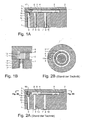
- FIG. 2A in a lateral cross-sectional representation by the pressure measuring arrangement and Fig. 2B in a perpendicular cross-sectional view through a connecting element shown in top view.
- Base body 1 On one side Base body 1 is arranged at least one electrode 4, 5, which forms one of the two electrode surfaces.
- the peripheral area sits on this side of the base body 1 a spacer element in the form of a glass solder electrically insulating material as a spacer and connecting element 2.
- connection element 2 On this connecting element 2 is one Membrane 3 arranged, on the underside of a membrane electrode 6 is arranged, which is the second electrode surface formed.
- Connection points 8 for external tapping of voltages of the electrodes 4 - 6 lead through the base body 1 tubular base vias 7. These have usually on electrically conductive wall material.
- To the Connection of the membrane electrode 6 also leads through a via opening 11a through the connecting element 2 therethrough.
- Connecting element 2 and base body 1 must have this via opening 11a in the connecting element 2 exactly aligns over the corresponding base via hole 7 lie. This requires accordingly additional operations, e.g. B. Providing a base body 1 and a connecting element 2 with previously attached markings and their orientation.
- connecting element 2 and base body 1 is a conductive material, for. B. more conductive Adhesive or conductive paste, in the base through hole 7 and above also in the connecting element via opening 11a filled in to bridge the distance between membrane 6 and base body 1 and thus an electrical connection between the one hand the membrane 3 and its membrane electrode 6 and on the other hand the corresponding base via hole 7 train.
- the paste is baked or the adhesive cured.
- the object of the invention is an improved Method for contacting a membrane electrode on a Basic body of a pressure measuring arrangement or a pressure measuring arrangement to provide with a simpler structure.
- This task is accomplished through a method of contacting a Membrane electrode on a base body of a pressure measuring arrangement with the steps of claim 1 or by a pressure measuring arrangement with the features of the claim 6 solved.
- the connecting element a connecting element through-plating between the connection point on the base body and the membrane or the membrane electrode on. Is the connection of membrane, connecting element and base body by heating and, if necessary, melting of the connecting element, is provided a conductive contact material in the base via hole subsequently.
- the contacting material uses a material from which, when activated, especially by heating, ions into the electrical penetrate insulating material and this in the appropriate Make section conductive and thereby a Form through-connection to the membrane.
- the intrusion can be done in particular by diffusing and migrating.
- a pressure measuring arrangement has a connecting element plated-through hole from an electrically conductive Section with conductive ions in the otherwise electrical insulating material.
- the electrically insulating material is advantageous Glass, in particular glass, which is made from used in the assembly Glass solder is solidified by hardening and next to the Function of the connecting element for the firm connection of Membrane and body also function as a spacer takes over.
- a silver-containing material is preferred as the contact material Paste, especially silver paste or silver palladium paste used, which hardens by heating and thereby ions releases into the adjacent material of the connecting element.
- the contacting material is advantageously after the solidification of membrane, electrically insulating material as a connecting element and base body in the base body through-hole introduced so that a controlled Reaction by appropriate heating can be triggered.
- the membrane, the connecting element and the base body are glued together and there is no prior excessive heating.
- the creation of a field is particularly advantageous electric or electromagnetic field in order to Penetration of the ions from the contacting material into the electrically insulating material in a directional direction to support.
- FIG. 1A and 1B show a cross section and a section a preferred sensor, FIG. 1B being a shows slightly modified embodiment.
- the preferred Embodiment has a cylindrical cross section, similar to that of the sensor according to FIG. 2B.
- a capacitive measuring cell for detecting a Pressure at which the capacity depends on the pressure between two opposite and each other spaced and isolated electrode surfaces is determined.
- the second Electrode surface is on the inside of one Base body 1 arranged. The inside is the Arrangement in between the membrane 3 and the base body 1 understood space.
- the membrane 3 and the base body 1 are spaced apart and consist of an electrical non-conductive material.
- the connection between the membrane 3 and the base body 1 takes place via a connecting element 2, which in addition to the connection function at the same time the function of a spacer having.
- the connecting element 2 advantageously consists made of glass, which is formed from glass solder and a solid non-detachable and insulating connection of the membrane 3 and Forms base body 1.
- a reference electrode on the surface of the base body 1 5, which spaces the circular measuring electrode 4 surrounded.
- the electrodes 4 - 6 consist of a highly conductive material, in particular Gold. These connection points serve, for example as solder pads or other common taps for connecting the Pressure sensor to evaluation electronics, for example.
- the electrical connection between the connection points 8 and the respectively assigned one of the electrodes 4-6 takes place via Vias 7, which lead through the base body 1.
- For connecting the measuring electrode 4 and the Reference electrode 5 can be a simple one Act leader. In the illustrated embodiment however, the measuring electrode 4 and the reference electrode 5 tubular via openings 7 connected, wherein the via openings 7 a conductive wall 10 for establishing the electrical connection between the Junction 8 and the corresponding electrode 4 or 5 exhibit.
- the Base body 1 also has a via opening 7 from a connection point 8 to a connection point 9 between the base body 1 and the connecting element 2.
- Das Connection element 2 consists of an electrically insulating Material, especially one made of glass solder Vitreous.
- This connection point 12 is off in accordance with the embodiment shown in FIG. 1A an electrically conductive contact element, which forms an electrical connection to the membrane electrode 6 and provides.
- the one shown in Fig. 1B This junction is carried out directly by the embodiment Membrane electrode 6 formed, which extends into the area the junction 12 extends.
- connection point 9 and the junction 12 To make an electrical connection through the otherwise electrical insulating connecting element 2 between the connection point 9 and the junction 12 is trained at Production of the pressure sensor a contacting material 13 provided in the via opening 7.
- the provision takes place depending on the previous and subsequent required manufacturing steps before or after assembly of base body 1, connecting element 2 and Membrane 3 and hardening of the connecting element 2 by, for example a strong heating of glass solder.
- the contacting material 13 consists of a material which, when appropriately activated, ions releases to the adjacent material of the connecting element 2.
- a silver-containing is preferred as the contacting material 13 Paste, especially silver paste or silver palladium paste, which amplifies silver ions in when heated the material of the connecting element 2, so preferably in Glass or glass solder can wander. Otherwise it will electrically insulating material of the connecting element 2 in the area between the connection point 9 on the base body 1 to the connecting element 2 on the one hand and on the other hand the connection point 12 on the membrane 3 to the connecting element 2 electrically conductive.
- a continuous electrical Contacting is therefore from the external connection point 8 via the conductive wall material 10 of the via opening 7, the area of the connection point 9 between Base body 1 and the via 11 thus produced through the still solid body of the connecting element 2 to the connection point 12 between the connecting element 2 and the membrane 3 and above to the membrane electrode 6 educated.
- the preferred embodiment has no such Material weakening of the connecting element 2 by Through opening (11a in Fig. 2A) or one with a through hole filled with a contacting material.
- the assembly can be done without a special orientation of membrane 3, connecting element 2 and base body 1 with a view of via openings. This requires less work, fewer operations during production and thus a cost reduction.
- it does not apply the mechanical weak point in the connecting element 2 because the otherwise electrically insulating material of the connecting element 2 during a temperature process by a Ion migration from the contacting material 13 locally conductive is made.
- a via opening 7, 10 through the base body 1 a base body 1 can of course also be provided with a massive electrical wire led to a receiving space for the contacting material 13 is.
- the receiving space can be a recess, for example be in the area of the surface of the base body 1, which after assembly, the connecting element 2 opposite lies.
Landscapes
- Chemical & Material Sciences (AREA)
- Engineering & Computer Science (AREA)
- Ceramic Engineering (AREA)
- Physics & Mathematics (AREA)
- General Physics & Mathematics (AREA)
- Measuring Fluid Pressure (AREA)
- Investigating Or Analyzing Materials By The Use Of Electric Means (AREA)
- Electroplating Methods And Accessories (AREA)
Abstract
Description
- Fig. 1A
- einen Querschnitt durch eine Druck-Messanordnung in seitlicher Ansicht;
- Fig. 1B
- einen vergrößerten Ausschnitt davon;
- Fig. 2A
- einen seitlichen Querschnitt durch eine Anordnung gemäß dem Stand der Technik und
- Fig. 2B
- einen Querschnitt durch ein Verbindungselement in einer Ebene senkrecht zur Darstellung von Fig. 2A.
- 1
- Grundkörper
- 2
- elektrisch isolierendes Verbindungselement
- 3
- Membran
- 4
- Messelektrode
- 5
- Referenzelektrode
- 6
- Membranelektrode
- 7
- Durchkontaktierungs-Öffnung
- 8
- Anschlussstelle, extern an 1
- 9
- Verbindungsstelle von 1 zu 2
- 10
- Wandung in 7/leitendes Wandungsmaterial
- 11
- Verbindungselement- Durchkontaktierung/leitfähiger Glasabschnitt
- 11a
- Verbindungselement-Durchkontaktierungs-Öffnung
- 12
- Anschlussstelle von 2 zu 3/6
- 13
- Kontaktierungsmaterial
Claims (10)
- Verfahren zum Kontaktieren einer Membranelektrode (6) einer Druck-Messanordnung mit den Schritten:Verbinden einer Membran (3), an der die Membranelektrode (6) angeordnet ist, mit einem Grundkörper (1) über ein Verbindungselement (2) aus einem elektrisch isolierenden Material zwischen diesen, wobei der Grundkörper (1) eine Durchkontaktierung (7, 10) zwischen einer Anschlussstelle (8) und einer Verbindungsstelle (9) zum elektrisch isolierenden Material (2) aufweist und das Verbindungselement (2) eine,Verbindungselement-Durchkontaktierung (11) zwischen der Verbindungsstelle (9) und der Membran (3) oder Membranelektrode (6) aufweist,Bereitstellen eines leitfähigen Kontaktierungsmaterials (13) in der Durchkontaktierung (7, 10) undAktivieren, insbesondere Verfestigen durch Erhitzen lassen des Kontaktierungsmaterials (13),
dadurch gekennzeichnet, dassals das Kontaktierungsmaterial (13) ein Material verwendet wird, aus dem beim Aktivieren, insbesondere Erhitzen, Ionen in das elektrisch isolierende Material eindringen und dieses unter Ausbildung der Verbindungselement-Durchkontaktierung (11) leitfähig machen. - Verfahren nach Anspruch 1, bei dem als das elektrisch isolierende Material des Verbindungselements (2) Glas, insbesondere Glaslot verwendet wird.
- Verfahren nach Anspruch 1 oder 2, bei dem als das Kontaktierungsmaterial (13) silberhaltige Paste, insbesondere Silberpaste oder Silber-Palladium-Paste verwendet wird.
- Verfahren nach einem vorstehenden Anspruch, bei dem das Kontaktierungsmaterial (13) nach dem verfestigten Zusammensetzen von Membran (3), Verbindungselement (2) und Grundkörper (1) in die als Durchkontaktierungs-Öffnung (7, 10) ausgebildete Durchkontaktierung durch den Grundkörper (1) eingefüllt wird.
- Verfahren nach einem vorstehenden Anspruch, bei dem beim Aktivieren des Kontaktierungsmaterials (13) ein Feld, insbesondere ein elektrisches oder elektromagnetisches Feld über zumindest den Bereich der Verbindungselement-Durchkontaktierung (11) zum gerichteten Eindringen der Ionen angelegt wird.
- Druck-Messanordnung, insbesondere hergestellt mit einem Verfahren nach einem vorstehenden Anspruch, miteiner Membran (3),zumindest einer Elektrode (6) an der Membran (3),einem Grundkörper (1),einem Verbindungselement (2) aus einem elektrisch isolierenden Material zwischen Membran (3) und Grundkörper (1),einer Grundkörper-Durchkontaktierung (7, 10) von einer Anschlussstelle (8) am Grundkörper (1) zu einer Verbindungsstelle (9) zwischen Grundkörper (1) und dem Verbindungselement (2) undeiner Verbindungselement-Durchkontaktierung (11) von einer Anschlussstelle (12) an der Membran (3) oder Elektrode (6) an der Membran (3) und dem Verbindungselement (2) durch das Verbindungselement (2) hindurch zu der Verbindungsstelle (9) zum Grundkörper (1),
dadurch gekennzeichnet, dassdie Verbindungselement-Durchkontaktierung (11) aus einem elektrisch leitfähigen Abschnitt mit elektrisch leitfähigen Ionen in dem ansonsten elektrisch isolierenden Material ausgebildet ist. - Messanordnung nach Anspruch 6, bei der die Grundkörper-Durchkontaktierung (7, 10) ein elektrisch leitfähiges Kontaktierungsmaterial (13) enthält, welches beim Aktivieren, insbesondere beim Erhitzen die elektrisch leitfähigen Ionen abgibt.
- Messanordnung nach Anspruch 6 oder 7, bei der das Kontaktierungsmaterial (13) silberhaltig ist, insbesondere eine Silberpaste oder Silber-Palladium-Paste ist.
- Messanordnung nach einem der Ansprüche 6 - 8, bei der das elektrisch isolierende Material des Verbindungselements (2) Glas, insbesondere erhärtetes Glaslot ist.
- Messanordnung nach einem der Ansprüche 6 - 9, bei der die Verbindungselement-Durchkontaktierung (11) ursprünglich aus dem Kontaktierungsmaterial (13) stammende Ionen aufweist.
Applications Claiming Priority (2)
| Application Number | Priority Date | Filing Date | Title |
|---|---|---|---|
| DE10320478 | 2003-05-08 | ||
| DE10320478A DE10320478B3 (de) | 2003-05-08 | 2003-05-08 | Druck-Messanordnung mit einer Durchkontaktierung durch einen Distanzhalter zwischen einer Membran und einem Grundkörper sowie Verfahren zum Kontaktieren |
Publications (2)
| Publication Number | Publication Date |
|---|---|
| EP1475623A1 true EP1475623A1 (de) | 2004-11-10 |
| EP1475623B1 EP1475623B1 (de) | 2006-05-31 |
Family
ID=32731176
Family Applications (1)
| Application Number | Title | Priority Date | Filing Date |
|---|---|---|---|
| EP04007428A Expired - Lifetime EP1475623B1 (de) | 2003-05-08 | 2004-03-26 | Druckmessvorrichtung mit Durchkontaktierung sowie Kontaktierungsverfahren |
Country Status (4)
| Country | Link |
|---|---|
| US (1) | US7066030B2 (de) |
| EP (1) | EP1475623B1 (de) |
| CN (1) | CN100380106C (de) |
| DE (2) | DE10320478B3 (de) |
Cited By (1)
| Publication number | Priority date | Publication date | Assignee | Title |
|---|---|---|---|---|
| US6016607A (en) * | 1997-03-27 | 2000-01-25 | Sandia Corporation | Coordinated X-Y stage apparatus |
Families Citing this family (7)
| Publication number | Priority date | Publication date | Assignee | Title |
|---|---|---|---|---|
| DE102007026243A1 (de) * | 2007-06-04 | 2008-12-11 | Endress + Hauser Gmbh + Co. Kg | Kapazitiver Drucksensor |
| TWI383130B (zh) * | 2009-07-13 | 2013-01-21 | Univ Nat Taiwan | 電容式壓力感測器裝置及其製造方法 |
| DE102010003145A1 (de) * | 2010-03-23 | 2011-09-29 | Endress + Hauser Gmbh + Co. Kg | Drucksensor |
| JP2012247372A (ja) * | 2011-05-30 | 2012-12-13 | Nippon Mektron Ltd | 圧力センサ及びその製造方法並びに圧力検出モジュール |
| DE102011084612A1 (de) | 2011-10-17 | 2013-04-18 | Endress + Hauser Gmbh + Co. Kg | Keramische Druckmesszelle mit kapazitivem Wandler |
| DE102014101700A1 (de) * | 2014-02-12 | 2015-08-13 | Vega Grieshaber Kg | Druckmesszelle |
| CN110044537A (zh) * | 2019-03-27 | 2019-07-23 | 西人马联合测控(泉州)科技有限公司 | 压力传感器及其制造方法 |
Citations (2)
| Publication number | Priority date | Publication date | Assignee | Title |
|---|---|---|---|---|
| DE4231120A1 (de) * | 1992-09-17 | 1994-03-24 | Vdo Schindling | Drucksensor |
| DE10052053A1 (de) * | 2000-10-19 | 2002-04-25 | Endress Hauser Gmbh Co | Druckmeßzelle |
Family Cites Families (13)
| Publication number | Priority date | Publication date | Assignee | Title |
|---|---|---|---|---|
| GB1450709A (en) * | 1973-12-31 | 1976-09-29 | Birchall D J | Pressure transducers |
| US4839700A (en) * | 1987-12-16 | 1989-06-13 | California Institute Of Technology | Solid-state non-volatile electronically programmable reversible variable resistance device |
| US5561247A (en) * | 1993-03-30 | 1996-10-01 | Honda Motor Co., Ltd. | Pressure sensor |
| US5436795A (en) * | 1994-03-28 | 1995-07-25 | Texas Instruments Incorporated | Pressure transducer apparatus and method for making same |
| EP0797084B1 (de) * | 1996-03-23 | 2001-01-17 | Endress + Hauser GmbH + Co. | Verfahren zum Herstellen von kapazitiven, in Nullpunkt-Langzeit-Fehlerklassen sortierten Keramik-Absolutdruck-Sensoren |
| US5983727A (en) * | 1997-08-19 | 1999-11-16 | Pressure Profile Systems | System generating a pressure profile across a pressure sensitive membrane |
| US6184096B1 (en) * | 1997-11-05 | 2001-02-06 | Micron Technology, Inc. | Semiconductor processing method of providing dopant impurity into a semiconductor substrate |
| US6267009B1 (en) * | 1998-12-14 | 2001-07-31 | Endress + Hauser Gmbh + Co. | Capacitive pressure sensor cells or differential pressure sensor cells and methods for manufacturing the same |
| DE19910078A1 (de) * | 1999-03-08 | 2000-09-28 | Bosch Gmbh Robert | Verfahren zur Erhöung der Fertigungssicherheit von Lötverbindungen |
| US6578427B1 (en) * | 1999-06-15 | 2003-06-17 | Envec Mess- Und Regeltechnik Gmbh + Co. | Capacitive ceramic relative-pressure sensor |
| DE19960338A1 (de) * | 1999-12-15 | 2001-07-05 | Bosch Gmbh Robert | Gassensor zur Bestimmung der Konzentration von Gaskomponenten in Gasgemischen und dessen Verwendung |
| DE10122414A1 (de) * | 2001-05-09 | 2002-11-14 | Giesecke & Devrient Gmbh | Durchkontaktierung von flexiblen Leiterplatten |
| US6536287B2 (en) * | 2001-08-16 | 2003-03-25 | Honeywell International, Inc. | Simplified capacitance pressure sensor |
-
2003
- 2003-05-08 DE DE10320478A patent/DE10320478B3/de not_active Expired - Fee Related
-
2004
- 2004-03-26 DE DE502004000644T patent/DE502004000644D1/de not_active Expired - Lifetime
- 2004-03-26 EP EP04007428A patent/EP1475623B1/de not_active Expired - Lifetime
- 2004-04-26 CN CNB2004100384309A patent/CN100380106C/zh not_active Expired - Fee Related
- 2004-05-04 US US10/837,907 patent/US7066030B2/en not_active Expired - Lifetime
Patent Citations (2)
| Publication number | Priority date | Publication date | Assignee | Title |
|---|---|---|---|---|
| DE4231120A1 (de) * | 1992-09-17 | 1994-03-24 | Vdo Schindling | Drucksensor |
| DE10052053A1 (de) * | 2000-10-19 | 2002-04-25 | Endress Hauser Gmbh Co | Druckmeßzelle |
Cited By (1)
| Publication number | Priority date | Publication date | Assignee | Title |
|---|---|---|---|---|
| US6016607A (en) * | 1997-03-27 | 2000-01-25 | Sandia Corporation | Coordinated X-Y stage apparatus |
Also Published As
| Publication number | Publication date |
|---|---|
| DE502004000644D1 (de) | 2006-07-06 |
| CN1550767A (zh) | 2004-12-01 |
| HK1070941A1 (zh) | 2005-06-30 |
| US7066030B2 (en) | 2006-06-27 |
| DE10320478B3 (de) | 2004-08-19 |
| EP1475623B1 (de) | 2006-05-31 |
| CN100380106C (zh) | 2008-04-09 |
| US20040250627A1 (en) | 2004-12-16 |
Similar Documents
| Publication | Publication Date | Title |
|---|---|---|
| DE2624666C3 (de) | Verfahren zum elektrischen Miteinanderverbinden mehrerer übereinanderliegender flexibler Schaltkreise sowie dazu verwendbares nietartiges Kontaktstück | |
| EP2559327B1 (de) | Verfahren zur integration eines elektronischen bauteils in eine leiterplatte | |
| EP1986733B1 (de) | Vorrichtung mit flexiblem mehrschichtsystem zur kontaktierung oder elektrostimulation von lebenden gewebezellen oder nerven | |
| DE10243095B4 (de) | Wälzlager mit intergrierter Zustandsmessung | |
| EP3929594A1 (de) | Verfahren zur herstellung einer vorrichtung zur messung von stromstärken und vorrichtung zur messung von stromstärken | |
| DE3447396A1 (de) | Elektrischer druckgeber | |
| DE69429293T2 (de) | Autoglasscheibe mit einer gedruckten Leiterstruktur | |
| EP1475623B1 (de) | Druckmessvorrichtung mit Durchkontaktierung sowie Kontaktierungsverfahren | |
| WO2017162382A1 (de) | Deckel für ein gehäuse, batteriesensor und verfahren zum herstellen eines batteriesensors | |
| EP0268768A2 (de) | Sensor zur Überwachung von Wasserstoffkonzentrationen in Gasen | |
| DE102007041785A1 (de) | Halbleitervorrichtung und deren Herstellungsverfahren | |
| EP0997712A2 (de) | Kapazitive Sensoranordnung in einem flüssigen Medium sowie Herstellungsverfahren | |
| DE10313738A1 (de) | Kapazitiver mikromechanischer Drucksensor | |
| WO2008017556A2 (de) | Moldgehäuse in einpresstechnik | |
| DE4333348C2 (de) | Durchflußzelle mit einer ionenselektiven Elektrode | |
| DE10022772C1 (de) | Durchflußmeßsystem | |
| EP1238444B1 (de) | Unlösbare elektrische und mechanische verbindung, kontaktteil für eine unlösbare elektrische und mechanische verbindung und verfahren zur herstellung einer unlösbaren elektrischen und mechanischen verbindung | |
| DE10113474B4 (de) | Elektrische Schaltung | |
| DE3106354C2 (de) | Halbleitervorrichtung und Verfahren zu ihrer Herstellung | |
| EP2368837B1 (de) | Leiterplattensensor und Verfahren zur Herstellung desselben | |
| DE2610593A1 (de) | Verfahren zur herstellung elektrisch leitender kontaktbruecken, danach hergestellte kontaktbruecken an fluessigkristallzellen und anwendung der fluessigkristallzellen als anzeigeelement, insbesondere mit multiplex ansteuerung | |
| DE10206832B4 (de) | Verfahren zur Herstellung mikromechanischer Bauelemente mittels anodischem Bonden und mikromechanisches Bauelement | |
| DE10230711A1 (de) | Elektrisch leitende Verbindung | |
| EP0953151A1 (de) | Elektrochemische durchflusszelle | |
| EP4130697A1 (de) | Vorrichtung zur messung einer druckkraft und herstellungsverfahren für die vorrichtung |
Legal Events
| Date | Code | Title | Description |
|---|---|---|---|
| PUAI | Public reference made under article 153(3) epc to a published international application that has entered the european phase |
Free format text: ORIGINAL CODE: 0009012 |
|
| AK | Designated contracting states |
Kind code of ref document: A1 Designated state(s): AT BE BG CH CY CZ DE DK EE ES FI FR GB GR HU IE IT LI LU MC NL PL PT RO SE SI SK TR |
|
| AX | Request for extension of the european patent |
Extension state: AL LT LV MK |
|
| 17P | Request for examination filed |
Effective date: 20041211 |
|
| AKX | Designation fees paid |
Designated state(s): DE FR GB |
|
| GRAP | Despatch of communication of intention to grant a patent |
Free format text: ORIGINAL CODE: EPIDOSNIGR1 |
|
| GRAS | Grant fee paid |
Free format text: ORIGINAL CODE: EPIDOSNIGR3 |
|
| GRAA | (expected) grant |
Free format text: ORIGINAL CODE: 0009210 |
|
| AK | Designated contracting states |
Kind code of ref document: B1 Designated state(s): DE FR GB |
|
| REG | Reference to a national code |
Ref country code: GB Ref legal event code: FG4D Free format text: NOT ENGLISH |
|
| REF | Corresponds to: |
Ref document number: 502004000644 Country of ref document: DE Date of ref document: 20060706 Kind code of ref document: P |
|
| REG | Reference to a national code |
Ref country code: DE Ref legal event code: R096 Ref document number: 502004000644 Country of ref document: DE Effective date: 20060706 |
|
| GBT | Gb: translation of ep patent filed (gb section 77(6)(a)/1977) |
Effective date: 20060907 |
|
| ET | Fr: translation filed | ||
| PLBE | No opposition filed within time limit |
Free format text: ORIGINAL CODE: 0009261 |
|
| STAA | Information on the status of an ep patent application or granted ep patent |
Free format text: STATUS: NO OPPOSITION FILED WITHIN TIME LIMIT |
|
| 26N | No opposition filed |
Effective date: 20070301 |
|
| REG | Reference to a national code |
Ref country code: DE Ref legal event code: R097 Ref document number: 502004000644 Country of ref document: DE Effective date: 20070301 |
|
| REG | Reference to a national code |
Ref country code: FR Ref legal event code: PLFP Year of fee payment: 13 |
|
| REG | Reference to a national code |
Ref country code: FR Ref legal event code: PLFP Year of fee payment: 14 |
|
| REG | Reference to a national code |
Ref country code: FR Ref legal event code: PLFP Year of fee payment: 15 |
|
| PGFP | Annual fee paid to national office [announced via postgrant information from national office to epo] |
Ref country code: FR Payment date: 20210319 Year of fee payment: 18 |
|
| PGFP | Annual fee paid to national office [announced via postgrant information from national office to epo] |
Ref country code: GB Payment date: 20210324 Year of fee payment: 18 Ref country code: DE Payment date: 20210323 Year of fee payment: 18 |
|
| REG | Reference to a national code |
Ref country code: DE Ref legal event code: R119 Ref document number: 502004000644 Country of ref document: DE |
|
| GBPC | Gb: european patent ceased through non-payment of renewal fee |
Effective date: 20220326 |
|
| PG25 | Lapsed in a contracting state [announced via postgrant information from national office to epo] |
Ref country code: GB Free format text: LAPSE BECAUSE OF NON-PAYMENT OF DUE FEES Effective date: 20220326 Ref country code: FR Free format text: LAPSE BECAUSE OF NON-PAYMENT OF DUE FEES Effective date: 20220331 Ref country code: DE Free format text: LAPSE BECAUSE OF NON-PAYMENT OF DUE FEES Effective date: 20221001 |
|
| P01 | Opt-out of the competence of the unified patent court (upc) registered |
Effective date: 20230626 |