EP1475254A2 - Achseinbindung für Achsen von Fahrzeugen - Google Patents
Achseinbindung für Achsen von Fahrzeugen Download PDFInfo
- Publication number
- EP1475254A2 EP1475254A2 EP04006117A EP04006117A EP1475254A2 EP 1475254 A2 EP1475254 A2 EP 1475254A2 EP 04006117 A EP04006117 A EP 04006117A EP 04006117 A EP04006117 A EP 04006117A EP 1475254 A2 EP1475254 A2 EP 1475254A2
- Authority
- EP
- European Patent Office
- Prior art keywords
- square tube
- tube section
- axle body
- holding elements
- shaped recess
- Prior art date
- Legal status (The legal status is an assumption and is not a legal conclusion. Google has not performed a legal analysis and makes no representation as to the accuracy of the status listed.)
- Granted
Links
- 239000000725 suspension Substances 0.000 claims description 8
- 238000000034 method Methods 0.000 claims description 6
- 239000002184 metal Substances 0.000 claims description 4
- 230000000284 resting effect Effects 0.000 claims description 3
- 230000000295 complement effect Effects 0.000 claims description 2
- 238000003466 welding Methods 0.000 claims description 2
- 210000000056 organ Anatomy 0.000 description 3
- 235000011389 fruit/vegetable juice Nutrition 0.000 description 1
- 230000003993 interaction Effects 0.000 description 1
Images


Classifications
-
- B—PERFORMING OPERATIONS; TRANSPORTING
- B60—VEHICLES IN GENERAL
- B60G—VEHICLE SUSPENSION ARRANGEMENTS
- B60G9/00—Resilient suspensions of a rigid axle or axle housing for two or more wheels
- B60G9/003—Resilient suspensions of a rigid axle or axle housing for two or more wheels the axle being rigidly connected to a trailing guiding device
-
- B—PERFORMING OPERATIONS; TRANSPORTING
- B60—VEHICLES IN GENERAL
- B60G—VEHICLE SUSPENSION ARRANGEMENTS
- B60G11/00—Resilient suspensions characterised by arrangement, location or kind of springs
- B60G11/26—Resilient suspensions characterised by arrangement, location or kind of springs having fluid springs only, e.g. hydropneumatic springs
- B60G11/27—Resilient suspensions characterised by arrangement, location or kind of springs having fluid springs only, e.g. hydropneumatic springs wherein the fluid is a gas
-
- B—PERFORMING OPERATIONS; TRANSPORTING
- B60—VEHICLES IN GENERAL
- B60G—VEHICLE SUSPENSION ARRANGEMENTS
- B60G2200/00—Indexing codes relating to suspension types
- B60G2200/30—Rigid axle suspensions
- B60G2200/31—Rigid axle suspensions with two trailing arms rigidly connected to the axle
-
- B—PERFORMING OPERATIONS; TRANSPORTING
- B60—VEHICLES IN GENERAL
- B60G—VEHICLE SUSPENSION ARRANGEMENTS
- B60G2202/00—Indexing codes relating to the type of spring, damper or actuator
- B60G2202/10—Type of spring
- B60G2202/15—Fluid spring
- B60G2202/152—Pneumatic spring
-
- B—PERFORMING OPERATIONS; TRANSPORTING
- B60—VEHICLES IN GENERAL
- B60G—VEHICLE SUSPENSION ARRANGEMENTS
- B60G2204/00—Indexing codes related to suspensions per se or to auxiliary parts
- B60G2204/40—Auxiliary suspension parts; Adjustment of suspensions
- B60G2204/43—Fittings, brackets or knuckles
- B60G2204/4306—Bracket or knuckle for rigid axles, e.g. for clamping
Definitions
- the invention relates to an axle connection for axles of vehicles according to the preamble the two claims 1 and 2.
- a generic axle connection for axles of commercial vehicles is from the DE 100 54 839 A1.
- Carrying on the bellows Trailing arms is in each case a transverse to the direction of travel, approximately U-shaped Recess provided at the educated, horizontally extending base respectively a top or bottom of the square tube section of the axle body and on whose two vertically extending front and rear end faces each one, at the Front and rear of the square tube section of the axle body formed across the Direction of travel extending front and rear contact surface non-positive and positive comes to the supporting plant.
- At least one of the front or rear bearing surfaces of the square tube section of the axle body on such a machined surface on that the formed between the front and rear abutment surfaces outer contour of the square tube section positively with the defined opening distance of approximately U-shaped Recess of the respective trailing arm corresponds.
- axle connection for leaf or luftgefederte axles of vehicles with an axle body formed at least in sections as a square tube given, which in the area of its square tube section at its top or bottom from here directly or indirectly adjacent trailing arms or leaf spring organs crossed and with these by means of additional fasteners and optionally further holding elements is detachably connected.
- the leaf spring members are essentially releasably connected to the square tube of the axle body via retaining elements, wherein at least the leaf spring members next-ordered holding elements a transversely to the direction of travel extending, approximately U-shaped recess have, at the formed, horizontally extending base each have a top or bottom the square tube section of the axle body and at both vertically extending front and rear end faces in each case one at the front and rear of the square tube section of the axle body, running transversely to the direction of travel. and rear-side contact surface positive and positive locking to the supporting system comes.
- At least one of the front or rear bearing surfaces of the square tube section of the axle body on such a machined surface on that the formed between the front and rear abutment surfaces outer contour of the square tube section positively with the define opening distance of the at least one, approximately U-shaped recess of the respective holding element corresponds.
- the axle body By introducing the longitudinal forces in the top and / or bottom part of the wall the axle body can advantageously a possible deformation of the axle bridge under load, for example, when providing a welded axle bridge on a uncritical measure can be reduced.
- An otherwise with conventional axle connections usual introduction of the longitudinal forces in the axle body over the welds is at the solution according to the invention effectively avoided.
- At least one of the front or opposite rear surfaces of the square tube section of the axle body opposite its outer contour may be formed at least partially sublime.
- the front and rear side Contact surfaces of the square tube section of the axle body mainly each in the area their corners with minimal radii or sharp edges on the front and rear, vertical end faces of the trailing arm or the holding elements come to positive and non-positive attachment.
- the at least one, at least partially raised executed contact surface of the axle body either in one piece with this formed or adhered to this welding technology as a separate sheet metal strip or otherwise be joined.
- the at least one contact surface can after a Spanabaviden Process or after a calibration process and processed on such Defined measure be brought that the between the front and rear contact surfaces formed outer contour of the square tube section form-fitting with the defined Opening distance of the approximately U-shaped recess of the respective trailing arm or the respective recess of the respective holding element corresponds.
- the trailing arm by means of this suitable fastening means, such as screw or the like, indirectly or directly with the square tube sections of the axle body be connected.
- the trailing arm vertical bores have for receiving the fastener, which with in an upper or Lower side of the axle body arranged holding plate given vertical holes correspond.
- the leaf spring members by means of suitable fasteners such as spring clips or the like in Interaction with other holding elements indirectly with the square tube sections be connected to the axle body.
- the invention can as further holding elements at least one of the leaf spring member under or upper side resting spring plate and a leaf spring member upper or lower side underlaid retaining element provided be that the square tube section of the axle body partially with an approximately U-shaped Recess positively and positively encloses.
- the retaining element with further on the opposite side of the square tube section arranged holding elements the square tube section of the axle body in cooperation with spring clips clamp as further holding elements.
- the holding elements can either be formed as separate components or as a one-piece molded component.
- the holding plate or the holding elements above or below the square tube section as a separate trained Be arranged component.
- the square tube section with a thereto complementarily formed and extending transversely to the direction of travel U-shaped recess encompass positively and non-positively.
- the U-shaped recess of the Holding plate or the holding elements have a horizontally extending base, on which in each case an upper or lower side of the square tube section of the axle body comes to the plant.
- a further embodiment of the invention can at the two vertically extending front and rear end faces of the U-shaped recess of the retaining plate or the holding elements in each case one at the front and rear side of the square tube section formed of the axle body, extending transversely to the direction of travel front and rear side Contact surface positively and positively come to the supporting system.
- the front and rear side Contact surfaces of the square tube section of the axle body mainly each in the area their corners with minimal radii or sharp edges on the front and rear, vertical end faces of the holding plate or the holding elements for positive and non-positive system come.
- the trailing arm or the Retaining elements in addition to the transverse U-shaped recess a this have crossing, running approximately in the direction of travel U-shaped longitudinal recess, whose vertical end faces with on the raised abutment surfaces of the square tube section the Achs stressess given vertical steps paragraphs transverse to the direction of travel come to the side support system.
- the front side of the transverse to the direction of travel extending U-shaped recess of the trailing arm or the holding elements be given vertical, running longitudinally to the direction of contact surfaces that abut within the raised contact surfaces of the square tube section of the axle body Supported given vertical Jardinnab alternativesn transverse to the direction of travel.
- the one-piece with the axle body formed or provided as a separate component retaining plate at least one in Travel direction extending U-shaped L jossaus supraungsabexcellent, whose vertical end faces with on the raised contact surfaces of the square tube section of the axle body given vertical steps paragraphs transverse to the direction of 9.ab duenden Plant come.
- the vehicle may be a commercial vehicle, be provided a tractor or a trailer.
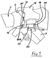
- Fig. 1 is a detail, in perspective and seen from the front one First embodiment of an axle connection for axles of vehicles shown.
- This one only partially shown axis is designed here, for example, air suspension and Belonging to a truck.
- the axis consists in this embodiment of a Axle body 1, which has at least partially a square tube section 2.
- the axle body 1 is in the region of its square tube section 2 at its top and Bottom of adjacent thereto, bellows 3 carrying trailing arms 4 crossed and releasably connected thereto by means of fastening means 14.
- fastening means 14 For the sake of simplicity Here is just one of the two trailing arms 4 and connected to these Section of the axle body 1 shown.
- the trailing arm 4 has in this embodiment, a transverse to the direction of travel, approximately U-shaped recess 8 (Fig. 3) on, at the educated, horizontal extending base 9 a bottom of the square tube section 2 of the Achs stressess 1 and at the two vertically extending front and rear end faces 10,11 each one at the front and rear of the square tube section. 2 formed of the axle body 1, extending transversely to the direction of travel front and rear side Contact surface 12,13 positive and positive fit to the supporting system.
- the fore and aft Rear abutment surfaces 12,13 are opposite the outer contour of the Square tube section 2 of the axle body 1 formed sublime.
- the contact surfaces 12,13 have such a machined surface that between the front and rear abutment surfaces 12,13 formed, projecting outer contour of the square tube section 2 positively with the defined opening portion of the approximately U-shaped Recess 8 of the trailing arm 4 corresponds.
- it may be an upper side the square tube section 2 of the axle body 1, which are of an approximately U-shaped Recess 8 of the trailing arm 4 embraced on the upper side under force and positive locking is.
- the trailing arm 4 vertical holes 15 for receiving the fastening means 14, which with in an upper side of the Achs stresses 1 arranged holding plate 16 given vertical holes 18 correspond.
- These holes 18 are here designed as threaded holes and take the fastening means 14 designed here as screws, for example.
- the given in the region of the square tube section 2 retaining plate 16 is here on the upper side the square tube section 2 arranged as a separate component and by means of the fastening means 14 attached.
- the area of the square tube section 2 given holding plate 16 may be given below the square tube section 2 and enclose this positive and non-positive.
- axle body 1 retaining plate be provided as forged, cast, welded or otherwise fastened fastening sections is formed.
- the attachment sections are used for Attachment of the fastening means 14, such as spring clip, screwing and the same.
- the optionally provided on the axle body 1 mounting portions may be required for receiving the fasteners 14 Have holes or recesses.
- the here provided in Fig. 1 as a separate component retaining plate 16 surrounds the square tube section 2 with a complementary formed and transverse to the direction of travel extending U-shaped recess 17 positive and non-positive.
- the U-shaped recess 17 (Fig. 1.3) of the holding plate 16 has a horizontally extending base 19, on which an upper side of the square tube section 2 of the axle body. 1 comes to the plant.
- At the two vertical front and rear end faces 20,21 of the U-shaped recess 17 of the support plate 16 are each one at the Front and rear side of the square tube section 2 of the axle body 1 formed transversely to the direction of travel extending front and rear bearing surface 12,13 force and positive fit to the supporting system.
- the front and rear side are Abutment surfaces 12,13 of the square tube section 2 of the axle body 1 raised trained and have such a kind of processed surface on that between the front and rear abutment surfaces 12,13 formed outer contour of the square tube section 2 positively with the defined opening distance of approximately U-shaped Recess 17 of the holding plate 16 corresponds.
- the front and back side contact surfaces 12,13 of the square tube section 2 of the axle body 1 are mainly in Area of their corners with minimal radii on the front and rear, vertical end faces 20,21 of the holding plate 16 for positive and non-positive contact.
- the trailing arms 4 shown in FIGS. 1 and 3 additionally have the direction transverse to the vehicle longitudinal direction extending U-shaped recess 8 a this crossing, approximately in Driving direction extending U-shaped longitudinal recess 22.
- Their vertical faces 23 come with a on the raised contact surfaces 12,13 of the square tube sections 2 of the axle body 1 given vertical stepped shoulder 24 transverse to the direction of travel to the side support system.
- Fig. 2 is a detail and in perspective view seen from the front one second embodiment of an axle connection for axles of commercial vehicles shown.
- cushioned on the trailing arm 4 air spring bellows cushioned.
- At the axis connection are the front side of the transverse to the direction of travel U-shaped recess 8 of Trailing arm 4 at this vertical and along the direction of travel extending contact surfaces 24 given given indented within the raised contact surfaces 12,13 support vertical steps paragraphs 28 transversely to the direction of travel.
- the longitudinally extending to the direction of travel vertical contact surfaces 27 are within of the trailing arm 4 in detail in Fig. 3, for receiving the fastening means 14 provided vertical holes 15 arranged.
- the fastening means 14 are executed here as screw.
- FIG. 3 is a detail of the axle body 1 of FIG. 1 in a sectional plane parallel shown to the vehicle longitudinal axis.
- a vehicle wheel only schematically indicated here is designated 29.
- the square tube section 2 of the welded in this istsbeipsiel executed, consisting of two body halves and with a weld 26 held Achs stressess 1 has front upper and lower abutment surfaces 12 and rear side upper and lower contact surfaces 13.
- the front and rear bearing surfaces 12,13 are raised and are formed in this embodiment of sheet metal strips, which means not shown here Tack welds on the square tube sections 2 of the axle 1 are fixed.
- the at least partially sublime running contact surfaces 12,13 of the axle body 1 either integrally formed with this or on this as glued separate sheet metal strips, soldered or otherwise joined.
- the contact surfaces 12,13 can after a chip removal process or after a calibration process be processed in such a way and brought to a defined degree that the between the front and rear abutment surfaces 12,13 formed outer contour of the square tube section 2 positively with the defined opening distance of approximately U-shaped Recess 8 of the respective trailing arm 4 corresponds.
- the front and rear bearing surfaces 12,13 of the square tube section 2 of the Achs stressess come predominantly each in the area of their designed with minimal radii Corners on the front and rear, vertical end faces 10,11 of the trailing arm 1 for positive and non-positive connection.
- the trailing arms 4 are suitable for this purpose, executed here as screwing Fastening means 14 arranged by means of an additionally above the axle body 1 and this frictionally and form-fitting comprehensive holding plate 16 with the Square tube sections 2 of the axle body 1 connected.
- the holding plate 16 has to Recording the fastener 14 vertical holes 18, here as threaded holes are executed.
- FIG. 4 front view is an axle body 1 of an air-sprung or leaf sprung Axis of a vehicle shown.
- a vehicle a commercial vehicle, such as be given a truck or bus, a semitrailer or a trailer.
- the axle body 1 has a square tube section 2, on the front and rear side raised contact surfaces 12,13 for non-positive and positive reception of the U-shaped Recess 8, for example, the air bag bearing a trailing arm 4 is arranged are.
- the raised contact surfaces 12,13 of recesses 47,48 be formed, which formed on leaf spring members 46 holding elements 40,41,42 formed are.
- either only lower or only upper contact surfaces 12,13 may be provided on the square tube section 2, which are arranged on the front and / or rear side.
- the contact surfaces 12,13 can only be sublime formed and possibly with step paragraphs 24,25,28 be provided.
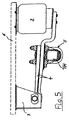
- FIG. 5 is a schematic and in side view arranged on a vehicle frame 6 Air suspension axle according to the prior art shown.
- the air suspension Axle consists of an axle body 1, the square tube section 2 of fasteners 5 enclosed and fixed on a multi-part trailing arm 4.
- Trailing arm 4 is niedes articulated to one fixed to the vehicle frame 6
- Console 7 tethered we carry another on its top one below against the vehicle frame 6 supporting air spring bellows.
- Fig. 6 is a fragmentary and perspective view obliquely from the front a third embodiment of an axle connection by means of a leaf spring member 46th shown sprung vehicle axle.
- the axle body 1 of the vehicle axle has a Square tube section 2, the raised projecting abutment surfaces 12, (13) accordingly the embodiments described above with such, the contact surfaces 12,13 opposite and formed on corresponding holding elements 40,41,42 front and rear end faces 50, 51, 60, 61 (FIG force fit to the plant come.
- an upper holding element 42 is arranged, which with an in Fig. 7 shown, U-shaped recess 48 between the front and back Contact surface 12,13 given upper outer contour of the square tube section. 2 engages positively and non-positively.
- a spring pad 43 resting, on which in turn the leaf spring member 46 is arranged.
- the leaf spring member 46 is a spring plate 44, which consists of two spring clips 45 is enclosed.
- the spring clip 45 are with their free ends through here Unspecified holes of the square tube section 2 underlaid lower Holding element 40 and a lower plate 41 and passed by means not shown here screwing against the retaining element 40 and the holding plate 41 braced, whereby the detachable connection of axle body 1 and leaf spring member 46 is realized.
- the holding member 40 and the holding plate 41 can be formed either by two separate components or by a common component be.
- Fig. 7 is fragmentary and in a sectional view in the vehicle longitudinal direction of shown in Figure 6 square tube section 2 of the axle body 1.
- a schema juice indicated vehicle wheel is provided with the reference numeral 29.
- the raised by the square tube section 2 raised upper front and Rear bearing surfaces 12,13 given upper contact contour of the axle body 1 is the upper side from the arranged in the upper support member 42, designed approximately U-shaped upper recess 48 received positively and non-positively.
- the upper recess 48 has the form-fitting reception of the upper contact contour of the square tube section 2 a horizontal base 49 and a vertical front and rear end face 60.61 on.
- a spring pad 43 On the upper support member 42 is a spring pad 43, on which in turn the leaf spring member 46 and the spring tension plate 44 is arranged.
- the spring plate 44 is connected by means of this encompassing spring clip 45 together with the leaf spring member 46th and the square tube section 2 against a the square tube section 2 under strenges, here integrally formed lower retaining element 40 braced.
- the upper holding element 42 shown here is together with the intermediate Spring pad 43 and the leaf spring member 46 against the spring clamping plate 44th connected by means of a heart bolt 39.
- Analogous to the upper receiving contour of the square tube section 2 is the lower, by the raised projecting front and rear bearing surfaces 12,13 given Receiving contour of the square tube section 2 of a within the lower holding element 40 given, approximately U-shaped recess 47 positively and positively received.
- the lower recess in this case has an approximately horizontal base 59th and at the contact surfaces 12,13 of the square tube section 2 respectively adjacent front and rear, about vertical faces 50,51 on.
Landscapes
- Engineering & Computer Science (AREA)
- Mechanical Engineering (AREA)
- Vehicle Body Suspensions (AREA)
Abstract
Description
- Fig. 1
- ausschnittsweise und in perspektivischer Darstellung von vorne gesehen eine erste Ausführungsart einer Achsanbindung für luftgefederte Fahrzeugachsen,
- Fig. 2
- ausschnittsweise und in perspektivischer Darstellung von vorne gesehen eine zweite Ausführungsart einer Achsanbindung für luftgefederte Fahrzeugachsen,
- Fig. 3
- ausschnittsweise einen Achskörper gemäß Fig. 1 in einer Schnittdarstellung in Fahrzeuglängsrichtung,
- Fig. 4
- in Vorderansicht einen Achskörper einer luftgefederten Fahrzeugachse gemäß Fig. 1 und Fig. 2,
- Fig. 5
- schematisch und in Seitenansicht eine an einem Fahrzeugrahmen angeordnete luftgefederte Fahrzeugachse gemäß dem Stand der Technik,
- Fig. 6
- ausschnittsweise und in perspektivischer Darstellung eine dritte Ausführungsart einer Achsanbindung einer mittels eines Blattfederorgans gefederten Fahrzeugachse und
- Fig. 7
- ausschnittsweise einen Achskörper gemäß Fig. 6 in einer Schnittdarstellung in Fahrzeuglängsrichtung.
Claims (16)
- Achsanbindung für blatt- oder luftgefederte Achsen von Fahrzeugen, mit einem zumindest abschnittsweise als Vierkantrohr ausgebildeten Achskörper (1), der im Bereich seines Vierkantrohrabschnittes (2) an seiner Ober- oder Unterseite von hieran mittelbar oder unmittelbar anliegenden Längslenkern (4) oder Blattfederorganen (46) gekreuzt und mit diesen mittels zusätzlicher Befestigungsmittel und gegebenenfalls weiterer Halteelemente lösbar verbunden ist, dadurch gekennzeichnet, dass an den Luftfederbälge (3) tragenden Längslenkern (4) jeweils eine quer zur Fahrtrichtung verlaufende, etwa U-förmig gestaltete Ausnehmung (8) vorgesehen ist, an deren gebildeter, horizontal verlaufender Grundfläche (9) jeweils eine Ober- oder Unterseite des Vierkantrohrabschnittes (2) des Achskörpers (1) und an deren beiden vertikal verlaufenden vorderen und hinteren Stirnseiten (10,11) jeweils eine, an der Vorder- und Hinterseite des Vierkantrohrabschnittes (2) des Achskörpers (1) gebildete, quer zur Fahrtrichtung verlaufende vorder- und hinterseitige Anlagefläche (12,13) kraft- und formschlüssig zur abstützenden Anlage kommt, und wobei wenigstens eine der vorder- oder hinterseitigen Anlageflächen (12,13) des Vierkantrohrabschnittes (2) des Achskörpers (1) eine solcherart bearbeitete Oberfläche aufweist, dass die zwischen den vorderen und hinteren Anlageflächen (12,13) gebildete Außenkontur des Vierkantrohrabschnittes (2) formschlüssig mit dem definierten Öffnungsabstand der etwa U-förmigen Ausnehmung (8) des jeweiligen Längslenkers (4) korrespondiert.
- Achsanbindung für blatt- oder luftgefederte Achsen von Fahrzeugen, mit einem zumindest abschnittsweise als Vierkantrohr ausgebildeten Achskörper (1), der im Bereich seines Vierkantrohrabschnittes (2) an seiner Ober- oder Unterseite von hieran mittelbar oder unmittelbar anliegenden Längslenkern (4) oder Blattfederorganen (46) gekreuzt und mit diesen mittels zusätzlicher Befestigungsmittel und gegebenenfalls weiterer Halteelemente lösbar verbunden ist, dadurch gekennzeichnet, dass die Blattfederorgane (46) im wesentlichen über Halteelemente (40,41,42) lösbar mit dem Vierkantrohr des Achskörpers (1) verbunden sind, wobei zumindest die den Blattfederorganen (46) nächstgeordneten Halteelemente (42) eine quer zur Fahrtrichtung verlaufende, etwa U-förmig gestaltete Ausnehmung (47,48) aufweisen, an deren gebildeter, horizontal verlaufender Grundfläche (49,59) jeweils eine Ober- oder Unterseite des Vierkantrohrabschnittes (2) des Achskörpers (1) und an deren beiden vertikal verlaufenden vorderen und hinteren Stirnseiten (60,61;50,51) jeweils eine an der Vorder- und Hinterseite des Vierkantrohrabschnittes (2) des Achskörpers (1) gebildete, quer zur Fahrtrichtung verlaufende vorder- und hinterseitige Anlagefläche (12,13) kraft- und formschlüssig zur abstützenden Anlage kommt, und wobei wenigstens eine der vorder- oder hinterseitigen Anlageflächen (12,13) des Vierkantrohrabschnittes (2) des Achskörpers (1) eine solcherart bearbeitete Oberfläche aufweist, dass die zwischen den vorderen und hinteren Anlageflächen (12,13) gebildete Außenkontur des Vierkantrohrabschnittes (2) formschlüssig mit dem definierten Öffnungsabstand der wenigstens einen, etwa U-förmigen Ausnehmung (47,48) des jeweiligen Halteelementes (40,42) korrespondiert.
- Achsanbindung nach einem der Ansprüche 1 und 2, dadurch gekennzeichnet, dass wenigstens eine der vorder- oder hinterseitigen Anlageflächen (12,13) des Vierkantrohrabschnittes (2) des Achskörpers (1) gegenüber dessen Außenkontur zumindest teilweise erhaben ausgebildet ist.
- Achsanbindung nach einem der Ansprüche 1 bis 3, dadurch gekennzeichnet, dass die vorderund hinterseitigen Anlageflächen (12,13) des Vierkantrohrabschnittes (2) des Achskörpers (1) vorwiegend jeweils im Bereich ihrer mit minimalen Radien oder scharfen Kanten ausgestalteten Ecken an den vorderen und hinteren, vertikalen Stirnseitigen (10,11;60,61;50,51) des Längslenkers (1) beziehungsweise der Halteelemente (40,42) zur form- und kraftschlüssigen Anlage kommen.
- Achsanbindung nach einem der Ansprüche 1 bis 4, dadurch gekennzeichnet, dass die wenigstens eine, zumindest teilweise erhaben ausgeführte Anlagefläche (12,13) des Achskörpers (1) entweder einteilig mit diesem gebildet oder auf diesem als separater Blechstreifen schweißtechnisch angeheftet oder sonstwie gefügt ist, und dass die wenigstens eine Anlagefläche (12,13) nach einem spanabnehmenden Verfahren oder nach einem Kalibrierverfahren solcherart bearbeitet und auf definertes Maß gebracht ist, dass die zwischen den vorderen und hinteren Anlageflächen (12,13) gebildete Außenkontur des Vierkantrohrabschnittes (2) formschlüssig mit dem definierten Öffnungsabstand der etwa U-förmigen Ausnehmung (8) des jeweiligen Längslenkers (4) oder der betreffenden Ausnehmung (47,48) des jeweiligen Halteelementes (40,42) korrespondiert.
- Achsanbindung nach einem der Ansprüche 1 und 3 bis 5, dadurch gekennzeichnet, dass die Längslenker (4) mittels hierfür geeigneter Befestigungsmittel (14) wie beispielsweise Verschraubungselemente oder dergleichen, mittelbar oder unmittelbar mit den Vierkantrohrabschnitten (2) des Achskörpers (1) verbunden sind.
- Achsanbindung nach einem der Ansprüche 1 und 3 bis 5, dadurch gekennzeichnet, dass die Längslenker (4) Vertikalbohrungen (15) zur Aufnahme der Befestigungsmittel (14) aufweisen, welche mit in einer ober- oder unterseitig des Achskörpers (1) angeordneten Halteplatte (16) gegebenen vertikalen Bohrungen (18) korrespondieren.
- Achsanbindung nach einem der Ansprüche 2 bis 5, dadurch gekennzeichnet, dass die Blattfederorgane (46) mittels hierfür geeigneter Befestigungsmittel (44,45) wie beispielsweise Federbügel (45) oder dergleichen im Zusammenwirken mit weiteren Halteelementen (39,40,41,42,43) mittelbar mit den Vierkantrohrabschnitten (2) des Achskörpers (1) verbunden sind.
- Achsanbindung nach Anspruch 8, dadurch gekennzeichnet, dass als weitere Halteelemente (39,40,41,42,43) zumindest eine dem Blattfederorgen (46) unter- oder oberseitig aufliegende Federspannplatte (44) und ein dem Blattfederorgan (46) ober- oder unterseitig unterlegtes Halteelement (42) vorgesehen ist, das den Vierkantrohrabschnitt (2) des Achskörpers (1) bereichsweise mit einer etwa U-förmigen Ausehmung (48) kraft- und formschlüssig umschließt, und daß das Halteelment (42) mit weiteren, auf der gegenüberliegenden Seite des Vierkantrohrabschnittes (2) angeordneten Halteelementen (40,41) den Vierkantrohrabschnitt (2) des Achskörpers (1) im Zusammenwirken mit Federbügeln (45) als weitere Halteelemente einspannt.
- Achsanbindung nach Anspruch 9, dadurch gekennzeichnet, dass die Halteelemente (40,41) entweder als separate Bauteile oder als ein einteiliges Bauteil ausgebildet sind.
- Achsanbindung nach einem der Ansprüche 1 bis 9, dadurch gekennzeichnet, dass die im Bereich des Vierkantrohrabschnittes (2) gegebene Halteplatte (16) oder die gegebenen Halteelemente (40,41) entweder Bestandteil des Achskörpers (1) sind, oder dass die Halteplatte (16) oder die Halteelemente (40,41) ober- oder unterseitig des Vierkantrohrabschnittes (2) als separates Bauteil angeordnet sind.
- Achsanbindung nach Anspruch 1 bis 11, dadurch gekennzeichnet, dass die als separates Bauteil vorgesehene Halteplatte (16) oder die Halteelemente (40,41) und/oder das Halteelement (42) den Vierkantrohrabschnitt (2) mit einer hierzu komplementär ausgebildeten und quer zur Fahrtrichtung verlaufenden U-förmigen Ausnehmung (17;47,48) form- und kraftschlüssig umgreifen, und dassdie U-förmige Ausnehmung (17;47,48) der Halteplatte (16) oder der Halteelemente (40,41 ;42) eine horizontal verlaufende Grundfläche (19, 59; 49) aufweisen, an welcher jeweils eine Ober- oder Unterseite des Vierkantrohrabschnittes (2) des Achskörpers (1) zur Anlage kommt, und dassan den beiden vertikal verlaufenden vorderen und hinteren Stirnseiten (20,21;50,51;60,61) der U-förmigen Ausnehmung (17;47,48) der Halteplatte (16) oder der Halteelemente (40,41 ;42) jeweils eine an der Vorder- und Hinterseite des Vierkantrohrabschnittes (2) des Achskörpers (1) gebildete, quer zur Fahrtrichtung verlaufende vorder- und hinterseitige Anlagefläche (12,13) kraft- und formschlüssig zur abstützenden Anlage kommt, und dasswenigstens eine der vorder- oder hinterseitigen Anlageflächen (12,13) des Vertikantrohrabschnittes (2) der Achskörpers (1) gegebenenfalls teilweise erhaben ausgebildet und eine solcherart bearbeitete Oberfläche aufweist, dass die zwischen den vorderen und hinteren Anlageflächen (12,13) gebildete Außenkontur des Vierkantrohrabschnittes (2) formschlüssig mit dem definierten Öffnungsabstand der etwa U-förmigen Ausnehmung (17;47;48) der Halteplatte (16) oder der Halteelemente (40,41;42) korrespondiert, und dassdie vorder- und hinterseitigen Anlageflächen (12,13) des Vierkantrohrabschnittes (2) des Achskörpers (1) vorwiegend jeweils im Bereich ihrer mit minimalen Radien oder scharfen Kanten ausgestalteten Ecken an den vorderen und hinteren, vertikalen Stirnseiten (20,21;50,51;60,61) der Halteplatte (16) oder der Halteelemente (40,41;42) zur form- und kraftschlüssigen Anlage kommen.
- Achsanbindung nach einem oder mehreren der vorangegangenen Ansprüche 1 bis 12, dadurch gekennzeichnet, dass die Längslenker (4) oder die Halteelemente (40,41;42) zusätzlich zur quer verlaufenden U-förmigen Ausnehmung (8;47;48) eine diese kreuzende, etwa in Fahrtrichtung verlaufende U-förmige Längsausnehmung (22) aufweisen, deren vertikale Stirnseiten (23) mit auf den erhabenen Anlageflächen (12,13) des Vierkantrohrabschnittes (2) des Achskörpers (1) gegebenen vertikalen Stufenabsätzen (24) quer zur Fahrtrichtung zur seitenabstützenden Anlage kommen.
- Achsanbindung nach einem oder mehreren der vorangegangenen Ansprüche 1 bis 13, dadurch gekennzeichnet, dass stirnseitig der quer zur Fahrtrichtung verlaufenden U-förmigen Ausnehmung (8;47;48) der Längslenker (4) oder der Halteelemente (40,41;42) jeweils vertikale, längs zur Fahrtrichtung verlaufende Anlageflächen (27) gegeben sind, die sich an innerhalb der erhabenen Anlageflächen (12,13) des Vierkantrohrabschnittes (2) des Achskörpers (1) eingerückt gegebenen vertikalen Stufenabsätzen (28) quer zur Fahrtrichtung abstützen.
- Achsanbindung nach einem oder mehreren der vorangegangenen Ansprüche 1 bis 14, dadurch gekennzeichnet, dass die einteilig mit dem Achskörper (1) gebildete oder die als separates Bauteil vorgesehene Halteplatte (16) wenigstens einen in Fahrtrichtung verlaufenden U-förmigen Längsausnehmungsabschnitt aufweist, dessen vertikale Stirnseiten mit auf den erhabenen Anlageflächen (12,13) des Vierkantrohrabschnittes (2) des Achskörpers (1) gegebenen vertikalen Stufenabsätzen (24,28) quer zur Fahrtrichtung zur seitenabstützenden Anlage kommen.
- Achsanbindung nach einem oder mehreren der vorangegangenen Ansprüche 1 bis 15, dadurch gekennzeichnet, dass als Fahrzeug ein Nutzfahrzeug, ein Sattelzug oder ein Anhänger vorgesehen ist.
Applications Claiming Priority (2)
| Application Number | Priority Date | Filing Date | Title |
|---|---|---|---|
| DE2003120218 DE10320218A1 (de) | 2003-05-05 | 2003-05-05 | Achsanbindung für Luftfederachsen von Fahrzeugen |
| DE10320218 | 2003-05-05 |
Publications (3)
| Publication Number | Publication Date |
|---|---|
| EP1475254A2 true EP1475254A2 (de) | 2004-11-10 |
| EP1475254A3 EP1475254A3 (de) | 2006-09-13 |
| EP1475254B1 EP1475254B1 (de) | 2007-09-05 |
Family
ID=32981246
Family Applications (1)
| Application Number | Title | Priority Date | Filing Date |
|---|---|---|---|
| EP20040006117 Expired - Lifetime EP1475254B1 (de) | 2003-05-05 | 2004-03-15 | Achseinbindung für Achsen von Fahrzeugen |
Country Status (2)
| Country | Link |
|---|---|
| EP (1) | EP1475254B1 (de) |
| DE (2) | DE10320218A1 (de) |
Cited By (4)
| Publication number | Priority date | Publication date | Assignee | Title |
|---|---|---|---|---|
| EP2081783A1 (de) * | 2006-10-31 | 2009-07-29 | Volvo Lastvagnar AB | Achsaufhängungsanordnung für schwerfahrzeug |
| DE102016012773A1 (de) | 2016-10-26 | 2017-06-01 | Daimler Ag | Achsanbindung für Achsen von Fahrzeugen |
| CN113840744A (zh) * | 2019-04-19 | 2021-12-24 | Vdl维维乐有限公司 | 在车轴的管状轴体中提供互锁凹部 |
| EP4008571A1 (de) * | 2020-12-01 | 2022-06-08 | Volvo Truck Corporation | Achseinbindung für achsen von fahrzeugen |
Families Citing this family (2)
| Publication number | Priority date | Publication date | Assignee | Title |
|---|---|---|---|---|
| DE102006044451A1 (de) * | 2006-09-21 | 2008-04-03 | Zf Friedrichshafen Ag | Anbindung des Abstützzylinders einer Fahrzeugachse an eine Achsbrücke |
| DE102012206641B4 (de) | 2012-04-23 | 2021-11-25 | Zf Friedrichshafen Ag | Achsbrücke einer Arbeitsmaschine |
Citations (1)
| Publication number | Priority date | Publication date | Assignee | Title |
|---|---|---|---|---|
| DE10054839A1 (de) | 2000-11-04 | 2002-05-08 | Daimler Chrysler Ag | Befestigung einer Fahrzeugachse an einer Achsaufhängung |
Family Cites Families (6)
| Publication number | Priority date | Publication date | Assignee | Title |
|---|---|---|---|---|
| US1872196A (en) * | 1928-12-10 | 1932-08-16 | Urschel Engineering Company | Tubular axle |
| US3437333A (en) * | 1966-10-24 | 1969-04-08 | North American Rockwell | Spring seat |
| US3773347A (en) * | 1972-04-12 | 1973-11-20 | Hutchens Ind | Axle attachment fitting |
| US4858949A (en) * | 1987-11-20 | 1989-08-22 | Lear Siegler Neway Corp. | Lightweight trailing arm suspension |
| DE4232779C1 (de) * | 1992-09-30 | 1994-02-17 | Bergische Achsen Kotz Soehne | Achskörper und Achseinbindung |
| DE9305039U1 (de) * | 1993-04-02 | 1994-08-04 | Trenkamp & Gehle | Vorrichtung zum Verbinden von Längslenkereinheiten mit einer Radachse von Nutzfahrzeugen |
-
2003
- 2003-05-05 DE DE2003120218 patent/DE10320218A1/de not_active Withdrawn
-
2004
- 2004-03-15 EP EP20040006117 patent/EP1475254B1/de not_active Expired - Lifetime
- 2004-03-15 DE DE200450004842 patent/DE502004004842D1/de not_active Expired - Lifetime
Patent Citations (1)
| Publication number | Priority date | Publication date | Assignee | Title |
|---|---|---|---|---|
| DE10054839A1 (de) | 2000-11-04 | 2002-05-08 | Daimler Chrysler Ag | Befestigung einer Fahrzeugachse an einer Achsaufhängung |
Cited By (6)
| Publication number | Priority date | Publication date | Assignee | Title |
|---|---|---|---|---|
| EP2081783A1 (de) * | 2006-10-31 | 2009-07-29 | Volvo Lastvagnar AB | Achsaufhängungsanordnung für schwerfahrzeug |
| EP2081783A4 (de) * | 2006-10-31 | 2010-01-20 | Volvo Lastvagnar Ab | Achsaufhängungsanordnung für schwerfahrzeug |
| DE102016012773A1 (de) | 2016-10-26 | 2017-06-01 | Daimler Ag | Achsanbindung für Achsen von Fahrzeugen |
| CN113840744A (zh) * | 2019-04-19 | 2021-12-24 | Vdl维维乐有限公司 | 在车轴的管状轴体中提供互锁凹部 |
| EP4008571A1 (de) * | 2020-12-01 | 2022-06-08 | Volvo Truck Corporation | Achseinbindung für achsen von fahrzeugen |
| US11767067B2 (en) | 2020-12-01 | 2023-09-26 | Volvo Truck Corporation | Joint for mounting an elongate element to a structural element in a vehicle |
Also Published As
| Publication number | Publication date |
|---|---|
| DE502004004842D1 (de) | 2007-10-18 |
| DE10320218A1 (de) | 2004-12-02 |
| EP1475254A3 (de) | 2006-09-13 |
| EP1475254B1 (de) | 2007-09-05 |
Similar Documents
| Publication | Publication Date | Title |
|---|---|---|
| DE19920051B4 (de) | Fahrschemel für eine Vorderachse eines Kraftfahrzeugs | |
| DE10219275B4 (de) | Fahrgestell für ein Nutzfahrzeug | |
| DE102006062840B4 (de) | Vorderachsträger, insbesondere für Kraftfahrzeuge | |
| DE19730404B4 (de) | Hilfsrahmen für Kraftfahrzeuge | |
| EP1634798A1 (de) | Verbindungsverfahren und Adapter für Zugköpfe und Anbauchassis | |
| DE102009042060A1 (de) | Strukturbauteil für Hinterrahmenstruktur eines Kraftfahrzeugs | |
| DE102006041664A1 (de) | Trägeranordnung für einen Lastkraftwagen | |
| DE19624242A1 (de) | Vorrichtung zur Querführung einer Starrachse eines Kraftfahrzeuges | |
| EP2114753B1 (de) | Achsträger für kfz | |
| DE102017128033A1 (de) | Modulare fahrzeugplattform und zugehörige verfahren | |
| DE19809281A1 (de) | Fahrgestell eines schweren Nutzfahrzeuges | |
| DE3437384A1 (de) | Fahrwerk fuer ein anhaengerfahrzeug | |
| EP1475254A2 (de) | Achseinbindung für Achsen von Fahrzeugen | |
| DE10018315A1 (de) | Achsaufhängung für eine luftgefederte Fahrzeugachse | |
| DE202005009101U1 (de) | Adapter für Zugköpfe und Anbauchassis | |
| DE102013003301A1 (de) | Fahrwerk für ein Nutzfahrzeug, Achskörper sowie Verfahren zum Herstellen eines Achskörpers | |
| DE19809279A1 (de) | Fahrgestell eines schweren Nutzfahrzeuges | |
| DE102007018167A1 (de) | Heckseitige Fahrzeugkarosseriestruktur | |
| DE102004015048B4 (de) | Anbindung eines Lagerhalters für ein Lager eines radführenden Lenkers eines Kraftfahrzeugs | |
| EP0764571B1 (de) | Vorderachsquerträger für ein Kraftfahrzeug | |
| DE202005006305U1 (de) | Adapter für Zugköpfe und Anbauchassis | |
| DE102009039807A1 (de) | Frontstruktur eines Kraftfahrzeugs | |
| DE102016206649A1 (de) | Hilfsrahmen für ein Fahrzeug | |
| DE10054839A1 (de) | Befestigung einer Fahrzeugachse an einer Achsaufhängung | |
| DE102006010130B4 (de) | Hilfsrahmen, insbesondere für Kraftfahrzeuge |
Legal Events
| Date | Code | Title | Description |
|---|---|---|---|
| PUAI | Public reference made under article 153(3) epc to a published international application that has entered the european phase |
Free format text: ORIGINAL CODE: 0009012 |
|
| AK | Designated contracting states |
Kind code of ref document: A2 Designated state(s): AT BE BG CH CY CZ DE DK EE ES FI FR GB GR HU IE IT LI LU MC NL PL PT RO SE SI SK TR |
|
| AX | Request for extension of the european patent |
Extension state: AL LT LV MK |
|
| PUAL | Search report despatched |
Free format text: ORIGINAL CODE: 0009013 |
|
| AK | Designated contracting states |
Kind code of ref document: A3 Designated state(s): AT BE BG CH CY CZ DE DK EE ES FI FR GB GR HU IE IT LI LU MC NL PL PT RO SE SI SK TR |
|
| AX | Request for extension of the european patent |
Extension state: AL LT LV MK |
|
| 17P | Request for examination filed |
Effective date: 20061205 |
|
| GRAP | Despatch of communication of intention to grant a patent |
Free format text: ORIGINAL CODE: EPIDOSNIGR1 |
|
| AKX | Designation fees paid |
Designated state(s): DE FR IT SE |
|
| GRAS | Grant fee paid |
Free format text: ORIGINAL CODE: EPIDOSNIGR3 |
|
| GRAA | (expected) grant |
Free format text: ORIGINAL CODE: 0009210 |
|
| AK | Designated contracting states |
Kind code of ref document: B1 Designated state(s): DE FR IT SE |
|
| REF | Corresponds to: |
Ref document number: 502004004842 Country of ref document: DE Date of ref document: 20071018 Kind code of ref document: P |
|
| REG | Reference to a national code |
Ref country code: SE Ref legal event code: TRGR |
|
| ET | Fr: translation filed | ||
| PLBE | No opposition filed within time limit |
Free format text: ORIGINAL CODE: 0009261 |
|
| STAA | Information on the status of an ep patent application or granted ep patent |
Free format text: STATUS: NO OPPOSITION FILED WITHIN TIME LIMIT |
|
| 26N | No opposition filed |
Effective date: 20080606 |
|
| REG | Reference to a national code |
Ref country code: FR Ref legal event code: CD |
|
| REG | Reference to a national code |
Ref country code: DE Ref legal event code: R081 Ref document number: 502004004842 Country of ref document: DE Owner name: MAN TRUCK & BUS AG, DE Free format text: FORMER OWNER: MAN NUTZFAHRZEUGE AKTIENGESELLSCHAFT, 80995 MUENCHEN, DE Effective date: 20110518 |
|
| REG | Reference to a national code |
Ref country code: FR Ref legal event code: PLFP Year of fee payment: 13 |
|
| PG25 | Lapsed in a contracting state [announced via postgrant information from national office to epo] |
Ref country code: IT Free format text: LAPSE BECAUSE OF NON-PAYMENT OF DUE FEES Effective date: 20160315 |
|
| REG | Reference to a national code |
Ref country code: FR Ref legal event code: PLFP Year of fee payment: 14 |
|
| PG25 | Lapsed in a contracting state [announced via postgrant information from national office to epo] |
Ref country code: IT Free format text: LAPSE BECAUSE OF NON-PAYMENT OF DUE FEES Effective date: 20160315 |
|
| PGRI | Patent reinstated in contracting state [announced from national office to epo] |
Ref country code: IT Effective date: 20170710 |
|
| REG | Reference to a national code |
Ref country code: FR Ref legal event code: PLFP Year of fee payment: 15 |
|
| REG | Reference to a national code |
Ref country code: DE Ref legal event code: R081 Ref document number: 502004004842 Country of ref document: DE Owner name: MAN TRUCK & BUS SE, DE Free format text: FORMER OWNER: MAN TRUCK & BUS AG, 80995 MUENCHEN, DE |
|
| PGFP | Annual fee paid to national office [announced via postgrant information from national office to epo] |
Ref country code: FR Payment date: 20230323 Year of fee payment: 20 |
|
| PGFP | Annual fee paid to national office [announced via postgrant information from national office to epo] |
Ref country code: SE Payment date: 20230317 Year of fee payment: 20 Ref country code: IT Payment date: 20230321 Year of fee payment: 20 Ref country code: DE Payment date: 20230328 Year of fee payment: 20 |
|
| REG | Reference to a national code |
Ref country code: DE Ref legal event code: R071 Ref document number: 502004004842 Country of ref document: DE |
|
| REG | Reference to a national code |
Ref country code: SE Ref legal event code: EUG |