EP1473465B2 - Compresseur - Google Patents
Compresseur Download PDFInfo
- Publication number
- EP1473465B2 EP1473465B2 EP04251692.2A EP04251692A EP1473465B2 EP 1473465 B2 EP1473465 B2 EP 1473465B2 EP 04251692 A EP04251692 A EP 04251692A EP 1473465 B2 EP1473465 B2 EP 1473465B2
- Authority
- EP
- European Patent Office
- Prior art keywords
- compressor
- inlet
- impeller wheel
- upstream
- annular
- Prior art date
- Legal status (The legal status is an assumption and is not a legal conclusion. Google has not performed a legal analysis and makes no representation as to the accuracy of the status listed.)
- Expired - Lifetime
Links
- 238000011144 upstream manufacturing Methods 0.000 claims description 25
- 239000000411 inducer Substances 0.000 claims description 9
- 230000004323 axial length Effects 0.000 description 5
- 230000007423 decrease Effects 0.000 description 2
- 230000000712 assembly Effects 0.000 description 1
- 238000000429 assembly Methods 0.000 description 1
- 238000005266 casting Methods 0.000 description 1
- 230000003247 decreasing effect Effects 0.000 description 1
- 238000010348 incorporation Methods 0.000 description 1
- 238000004519 manufacturing process Methods 0.000 description 1
- 238000000034 method Methods 0.000 description 1
- 238000012986 modification Methods 0.000 description 1
- 230000004048 modification Effects 0.000 description 1
Images

Classifications
-
- F—MECHANICAL ENGINEERING; LIGHTING; HEATING; WEAPONS; BLASTING
- F04—POSITIVE - DISPLACEMENT MACHINES FOR LIQUIDS; PUMPS FOR LIQUIDS OR ELASTIC FLUIDS
- F04D—NON-POSITIVE-DISPLACEMENT PUMPS
- F04D29/00—Details, component parts, or accessories
- F04D29/40—Casings; Connections of working fluid
- F04D29/42—Casings; Connections of working fluid for radial or helico-centrifugal pumps
- F04D29/4206—Casings; Connections of working fluid for radial or helico-centrifugal pumps especially adapted for elastic fluid pumps
- F04D29/4213—Casings; Connections of working fluid for radial or helico-centrifugal pumps especially adapted for elastic fluid pumps suction ports
-
- H—ELECTRICITY
- H02—GENERATION; CONVERSION OR DISTRIBUTION OF ELECTRIC POWER
- H02J—CIRCUIT ARRANGEMENTS OR SYSTEMS FOR SUPPLYING OR DISTRIBUTING ELECTRIC POWER; SYSTEMS FOR STORING ELECTRIC ENERGY
- H02J7/00—Circuit arrangements for charging or depolarising batteries or for supplying loads from batteries
- H02J7/34—Parallel operation in networks using both storage and other dc sources, e.g. providing buffering
- H02J7/35—Parallel operation in networks using both storage and other dc sources, e.g. providing buffering with light sensitive cells
-
- F—MECHANICAL ENGINEERING; LIGHTING; HEATING; WEAPONS; BLASTING
- F04—POSITIVE - DISPLACEMENT MACHINES FOR LIQUIDS; PUMPS FOR LIQUIDS OR ELASTIC FLUIDS
- F04D—NON-POSITIVE-DISPLACEMENT PUMPS
- F04D29/00—Details, component parts, or accessories
- F04D29/66—Combating cavitation, whirls, noise, vibration or the like; Balancing
- F04D29/68—Combating cavitation, whirls, noise, vibration or the like; Balancing by influencing boundary layers
- F04D29/681—Combating cavitation, whirls, noise, vibration or the like; Balancing by influencing boundary layers especially adapted for elastic fluid pumps
- F04D29/685—Inducing localised fluid recirculation in the stator-rotor interface
-
- H—ELECTRICITY
- H02—GENERATION; CONVERSION OR DISTRIBUTION OF ELECTRIC POWER
- H02J—CIRCUIT ARRANGEMENTS OR SYSTEMS FOR SUPPLYING OR DISTRIBUTING ELECTRIC POWER; SYSTEMS FOR STORING ELECTRIC ENERGY
- H02J7/00—Circuit arrangements for charging or depolarising batteries or for supplying loads from batteries
- H02J7/0047—Circuit arrangements for charging or depolarising batteries or for supplying loads from batteries with monitoring or indicating devices or circuits
-
- F—MECHANICAL ENGINEERING; LIGHTING; HEATING; WEAPONS; BLASTING
- F05—INDEXING SCHEMES RELATING TO ENGINES OR PUMPS IN VARIOUS SUBCLASSES OF CLASSES F01-F04
- F05D—INDEXING SCHEME FOR ASPECTS RELATING TO NON-POSITIVE-DISPLACEMENT MACHINES OR ENGINES, GAS-TURBINES OR JET-PROPULSION PLANTS
- F05D2270/00—Control
- F05D2270/01—Purpose of the control system
- F05D2270/10—Purpose of the control system to cope with, or avoid, compressor flow instabilities
- F05D2270/101—Compressor surge or stall
-
- Y—GENERAL TAGGING OF NEW TECHNOLOGICAL DEVELOPMENTS; GENERAL TAGGING OF CROSS-SECTIONAL TECHNOLOGIES SPANNING OVER SEVERAL SECTIONS OF THE IPC; TECHNICAL SUBJECTS COVERED BY FORMER USPC CROSS-REFERENCE ART COLLECTIONS [XRACs] AND DIGESTS
- Y10—TECHNICAL SUBJECTS COVERED BY FORMER USPC
- Y10S—TECHNICAL SUBJECTS COVERED BY FORMER USPC CROSS-REFERENCE ART COLLECTIONS [XRACs] AND DIGESTS
- Y10S415/00—Rotary kinetic fluid motors or pumps
- Y10S415/914—Device to control boundary layer
Definitions
- the present invention relates to a compressor.
- the invention relates to the inlet arrangement of a centrifugal compressor such as, for example, the compressor of a turbocharger.
- a compressor comprises an impeller wheel, carrying a plurality of blades (or vanes) mounted on a shaft for rotation within a compressor housing. Rotation of the impeller wheel causes gas (e.g. air) to be drawn into the impeller wheel and delivered to an outlet chamber or passage.
- gas e.g. air
- the outlet passage is in the form of a volute defined by the compressor housing around the impeller wheel and in the case of an axial compressor the gas is discharged axially.
- the impeller wheel is mounted to one end of a turbocharger shaft and is rotated by an exhaust driven turbine wheel mounted within a turbine housing at the other end of the turbocharger shaft.
- the shaft is mounted for rotation on bearing assemblies housed within a bearing housing positioned between the compressor and turbine housings.
- the compressor inlet has a structure that has become known as a "a map width enhanced” (MWE) structure.
- MWE map width enhanced
- An MWE structure is described for instance in EP 526 965 .
- the inlet of such an MWE compressor comprises two coaxial tubular inlet sections, an outer inlet section or wall forming the compressor intake and inner inlet section wall defining the compressor inducer, or main inlet.
- the inner inlet section is shorter than the outer inlet section and has an inner surface which is an extension of a surface of an inner wall of the compressor housing which is swept by edges of the impeller wheel blades.
- the arrangement is such that an annular flow path is defined between the two tubular inlet sections which is open at its upstream end and which is provided with apertures at its downstream end which communicate with the inner surface of the compressor housing which faces the impeller wheel.
- the pressure within the annular flow passage surrounding the compressor inducer is normally lower than atmospheric pressure and during high gas flow and high speed operation of the impeller wheel the pressure in the area swept by the impeller wheel is less than that in the annular passage.
- air hows inward from the annular passage to the impeller wheel thereby increasing the amount of air reaching the impeller wheel, and increasing the maximum flow capacity of the compressor.
- the flow through the impeller wheel drops, or as the speed of the impeller wheel drops, so the amount of air drawn into the impeller wheel through the annular passage decreases until equilibrium is reached.
- a further drop in the impeller wheel flow or speed results in the pressure in the area swept by the impeller wheel increasing above that within the annular passage and thus there is a reversal in the direction of air flow through the annular passage. That is, under such conditions air flows outward from the impeller wheel to the upstream end of the annular passage and is returned to the compressor intake for re-circulation. Increase in compressor gas flow or speed of the impeller wheel causes the reverse to happen, i.e. a decrease in the amount of air returned to the intake through the annular passage, followed by equilibrium, in turn followed by reversal of the air flow through the annular passage so that air is drawn in to the impeller wheel via the apertures communicating between the annular passage and the impeller.
- GB 2319809 seeks to improve on prior MWE compressor structures by extending the inlet to include a venturi. This compressor has the feature of the characterising portion of claim 1.
- Compressor operation is extremely unstable under surge conditions due to large fluctuations in pressure and mass flow rate through the compressor. For many applications, such as in a turbocharger where the compressor supplies air to a reciprocating engine, these fluctuation in mass flow rate are unacceptable. As a result there is a continuing requirement to extend the useable flow range of compressors by improving the surge margin.
- a compressor for compressing a gas comprising:
- the present invention provides an Improvement In surge margin by extending the length of the inner tubular wall/annular flow passage (with a conventional MWE compressor the dimensions L1/D and L2/D do not exceed 0.6 and 0.5 respectively). The most significant dimension is thought to be L2/D since this is effectively the length of the annular passage through which the air will flow at surge.
- compressors are often designed to be compact and occupy the smallest possible space so that the length of the inlet tends to be minimised.
- conventional casting techniques used to manufacture compressor housings favour shorter inlet dimensions. In other words the prior art has generally been moving towards shortened inlet dimensions.
- the compressor according to the present invention is suited for inclusion in a turbocharger.
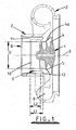
- the illustrated MWE compressor is a centrifugal compressor comprising an impeller wheel 1 mounted within a compressor housing 2 on one end of a rotating shaft (not shown) which extends along compressor axis 3.
- the impeller wheel 1 has a plurality of vanes 4 each of which has an outer edge 4a which sweeps across an inner housing surface 5 when the impeller wheel 1 rotates about the axis 3.
- the compressor housing 2 defines an outlet volute 6 surrounding the impeller wheel, and an MWE inlet structure comprising an outer tubular wall 7 extending outwardly upstream of the impeller 1 and defining an intake 8 for gas such as air, and an inner tubular wall 9 which extends part way in to the intake 8 and defines the compressor inducer 10.
- the inner surface of the inner wall 9 is an upstream extension of the housing wall surface 5 which is swept by the outside edges 4a of the impeller blades 4.
- An annular flow passage 11 is defined around the inducer 10 between the inner and outer walls 9 and 8 respectively.
- the flow passage 11 is open to the intake portion 8 of the inlet at its upstream end and is closed at its downstream end by an annular wall 12 of the housing 2, but communicates with the impeller wheel 1 via apertures 13 formed through the housing.
- the apertures 13 communicate between a downstream portion of the annular flow passage 11 and the inner surface 5 of the housing 2 which is swept by the outer edges 4a of the impeller wheel blades 4.
- the apertures 13 are typically defined by an annular slot bridged by circumferentially spaced web portions. There may for instance be four such web portions so that each aperture 13 extends approximately 90° around the impeller wheel 4.
- the apertures could however have other forms, for example comprising an annular array of relatively small diameter bores.
- the flow passage 11 thus has an overall axial length L1 defined between its upstream end (defined where the passage 11 opens to inlet) and its downstream end (the axially innermost point of the passage 11).
- the annular passage also has an axial length L2 defined between its upstream end and the axial location of the apertures 13, which corresponds to the axial length of the portion of the inner tubular wall extending upstream of the apertures 13.
- the conventional MWE compressor illustrated in Figure 1 operates as is described above in the introduction to this specification.
- air passes axially along the annular flow path 11 towards the impeller wheel 1, flowing to the impeller wheel 1 through the apertures 13.
- the direction of air flow through the annular flow passage 11 is reversed so that air passes from the impeller wheel, through the apertures 13, and through the annular flow passage 11 in an upstream direction and is reintroduced into the air intake 8 for re-circulation through the compressor.
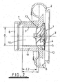
- Figure 2 illustrates a modification of the conventional MWE compressor of Figure 1 in accordance with a first embodiment of the present invention.
- Components which correspond to those of the compressor of Figure 1 are identified by the same reference numerals as used in Figure 1 .
- the illustrated compressor in accordance with the present invention is identical to the conventional MWE compressor of Figure 1 except that the axial length of the inlet is extended.
- the inner tubular wall 9 extends upstream of the compressor to greater extent than is conventional, and the length of the outer tubular wall 7 is similarly extended to accommodate the longer inner wall 9.
- the overall axial length L1 of the annular flow passage 11 is extended, as is the length L2.
- the present inventors have found that extending the length of the annular passage to the extent that L1/D > 0.65 and/or L2/D > 0.6, where D is the internal diameter of the inner tubular wall, greatly increases the surge margin of the compressor.
- the lower plot is the performance map which, as is well known, plots air flow rate through the compressor against the pressure ratio from the compressor inlet to outlet for a variety of impeller rotational speeds.
- the left hand line of the map represents the flow rates at which the compressor will surge for various turbocharger speeds and is known as the surge line.
- the compressor according to the present invention has a significantly improved surge margin, providing up to a 25% improvement on the surge margin of the conventional MWE compressor.
- the maximum flow (choke flow) is largely unaffected (shown by the right hand line of the map) as is the compressor efficiency (as shown by the upper plot of Figure 3 which plots the compressor efficiency as a function of air flow).
- the embodiment of the invention has a slightly increased pressure ratio capability compared to the conventional MWE compressor.
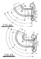
- the present invention relates to the length of the inlet and other aspects of the compressor and inlet structure may be entirely conventional. Moreover, the inlet need not be straight but could have one or more bends. Examples of embodiments of the present invention having curved inlet structures are illustrated in Figures 4a and 4b (which show the housing with impeller wheel omitted). In each case the inner and outer tubular walls 9 and 7 have extension portions 9a and 7a respectively which have axes that curve away from the axis 3 of the impeller (not shown). The two structures differ from each other only in the length and angle of curvature A of the curved portions 7a and 9a. With such embodiments the lengths L1 and L2 are measured along the axis of the tubular portions 7/7a and 9/9a which in these examples comprise both straight and curved portions. In other embodiments the lengths may be entirely curved.
- Compressors in accordance with the present invention may have many applications and in particular are suitable for incorporation in turbochargers.
Claims (6)
- Compresseur pour comprimer un gaz, le compresseur comprenant :un boîtier définissant un orifice d'entrée et un orifice de sortie ;une roue à hélices incluant une pluralité d'aubes montée rotativement dans le boîtier ;le boîtier ayant une paroi interne définissant une surface située à proximité immédiate des bords radialement externes des aubes d'hélices qui balayent ladite surface lorsque la roue à hélices tourne sur son axe ;dans lequel l'orifice d'entrée comprend :une paroi tubulaire externe s'étendant à l'écart de la roue à hélices dans une direction en amont et formant une partie d'entrée du gaz de l'orifice d'entrée ;une paroi tubulaire interne d'un diamètre interne D s'étendant à l'écart de la roue à hélices dans une direction en amont dans la paroi tubulaire externe et définissant une partie d'inducteur de l'orifice d'entrée ;un passage annulaire pour flux de gaz défini entre les parois tubulaires interne et externe et ayant une extrémité en amont et une extrémité en aval séparées par une longueur L1 mesurée le long de son axe, l'extrémité en amont du passage annulaire communiquant avec les parties d'entrée ou d'inducteur de l'orifice d'entrée à travers au moins une ouverture en amont ;au moins une ouverture en aval communiquant entre une partie en aval du passage annulaire pour flux et ladite surface du boîtier balayée par les aubes de l'hélice ;la paroi tubulaire interne s'étendant en amont de ladite au moins une ouverture en aval sur une longueur L2 mesurée le long de son axe ;où L1/D > 0,65 et/ou L2/D > 0,6 ;caractérisé en ce que le diamètre D est constant le long de substantiellement la longueur entière L2 de la paroi tubulaire interne.
- Compresseur selon la revendication 1, dans lequel L1/D > 0,9 et/ou L2/D > 0,97.
- Compresseur selon la revendication 1 ou la revendication 2, dans lequel le passage annulaire pour flux est ouvert à son extrémité en amont, de sorte que ladite au moins une ouverture en amont est une ouverture annulaire définie au niveau de l'extrémité en amont de la paroi tubulaire interne entre les parois tubulaires interne et externe.
- Compresseur selon l'une quelconque des revendications précédentes, dans lequel la paroi tubulaire interne et la paroi de passage annulaire sont coaxiales et ont un axe qui est une continuation de l'axe de la roue à hélices.
- Compresseur selon l'une quelconque des revendications précédentes, dans lequel les longueurs L1 et L2 sont entièrement droites.
- Compresseur selon l'une quelconque des revendications précédentes, dans lequel les longueurs L1 et L2 sont au moins en partie courbées.
Applications Claiming Priority (2)
| Application Number | Priority Date | Filing Date | Title |
|---|---|---|---|
| GB0309892 | 2003-04-30 | ||
| GB0309892 | 2003-04-30 |
Publications (3)
| Publication Number | Publication Date |
|---|---|
| EP1473465A1 EP1473465A1 (fr) | 2004-11-03 |
| EP1473465B1 EP1473465B1 (fr) | 2015-01-14 |
| EP1473465B2 true EP1473465B2 (fr) | 2018-08-01 |
Family
ID=32982444
Family Applications (1)
| Application Number | Title | Priority Date | Filing Date |
|---|---|---|---|
| EP04251692.2A Expired - Lifetime EP1473465B2 (fr) | 2003-04-30 | 2004-03-24 | Compresseur |
Country Status (5)
| Country | Link |
|---|---|
| US (1) | US7229243B2 (fr) |
| EP (1) | EP1473465B2 (fr) |
| JP (1) | JP2004332734A (fr) |
| KR (1) | KR101178213B1 (fr) |
| CN (1) | CN100394038C (fr) |
Families Citing this family (44)
| Publication number | Priority date | Publication date | Assignee | Title |
|---|---|---|---|---|
| CN100520085C (zh) * | 2004-06-15 | 2009-07-29 | 霍尼韦尔国际公司 | 与压气机外壳制成整体的消音器 |
| US7407364B2 (en) * | 2005-03-01 | 2008-08-05 | Honeywell International, Inc. | Turbocharger compressor having ported second-stage shroud, and associated method |
| US8511083B2 (en) | 2005-12-15 | 2013-08-20 | Honeywell International, Inc. | Ported shroud with filtered external ventilation |
| KR101184465B1 (ko) | 2005-12-20 | 2012-09-19 | 두산인프라코어 주식회사 | 엔진의 블로우바이 가스 압축용 터보차저 |
| US7698894B2 (en) * | 2006-05-22 | 2010-04-20 | International Engine Intellectual Property Company, Llc | Engine intake air compressor and method |
| FR2904375A1 (fr) * | 2006-07-26 | 2008-02-01 | Renault Sas | Dispositif pour l'admission d'air en entree d'un compresseur, notamment d'un turbocompresseur |
| GB0701012D0 (en) * | 2007-01-19 | 2007-02-28 | Cummins Turbo Tech Ltd | Compressor |
| US8857053B2 (en) * | 2007-08-29 | 2014-10-14 | Caterpillar Inc. | Compressor housing remanufacturing method and apparatus |
| GB0718846D0 (en) * | 2007-09-27 | 2007-11-07 | Cummins Turbo Tech Ltd | Compressor |
| AU2009291507B2 (en) * | 2008-09-11 | 2013-06-13 | Hunter Pacific International Pty Ltd | Extraction fan and rotor |
| US8210794B2 (en) * | 2008-10-30 | 2012-07-03 | Honeywell International Inc. | Axial-centrifugal compressor with ported shroud |
| US9518591B2 (en) * | 2008-11-18 | 2016-12-13 | Borgwarner Inc. | Compressor of an exhaust-gas turbocharger |
| DE102009052162B4 (de) * | 2009-11-06 | 2016-04-14 | Mtu Friedrichshafen Gmbh | Verdichteranordnung und Verfahren zur Herstellung einer solchen |
| DE102009054771A1 (de) | 2009-12-16 | 2011-06-22 | Piller Industrieventilatoren GmbH, 37186 | Turboverdichter |
| WO2011099416A1 (fr) * | 2010-02-09 | 2011-08-18 | 株式会社Ihi | Compresseur centrifuge faisant appel à un traitement pour carter à recirculation automatique asymétrique |
| US9816522B2 (en) | 2010-02-09 | 2017-11-14 | Ihi Corporation | Centrifugal compressor having an asymmetric self-recirculating casing treatment |
| EP2535597B1 (fr) * | 2010-02-09 | 2018-06-20 | IHI Corporation | Compresseur centrifuge faisant appel à un traitement pour carter à recirculation automatique asymétrique |
| JP5430684B2 (ja) * | 2010-02-09 | 2014-03-05 | 株式会社Ihi | 非軸対称自己循環ケーシングトリートメントを有する遠心圧縮機 |
| US9188129B2 (en) * | 2010-06-04 | 2015-11-17 | Borgwarner Inc. | Compressor of an exhaust-gas turbocharger |
| KR101741625B1 (ko) * | 2010-09-02 | 2017-05-30 | 보르그워너 인코퍼레이티드 | 환상 체적 내부로의 압축기 재순환 |
| JP5895343B2 (ja) * | 2011-01-24 | 2016-03-30 | 株式会社Ihi | 遠心圧縮機及び遠心圧縮機の製造方法 |
| JP5948892B2 (ja) | 2012-01-23 | 2016-07-06 | 株式会社Ihi | 遠心圧縮機 |
| JP5853721B2 (ja) | 2012-01-23 | 2016-02-09 | 株式会社Ihi | 遠心圧縮機 |
| JP2014198999A (ja) | 2012-02-23 | 2014-10-23 | 三菱重工業株式会社 | 圧縮機 |
| JP5920127B2 (ja) * | 2012-09-06 | 2016-05-18 | トヨタ自動車株式会社 | 過給機のデポジット除去装置 |
| CN102927060B (zh) * | 2012-11-02 | 2015-12-02 | 江苏大学 | 一种提高离心泵汽蚀性能的吸入口 |
| US9726185B2 (en) | 2013-05-14 | 2017-08-08 | Honeywell International Inc. | Centrifugal compressor with casing treatment for surge control |
| US10107296B2 (en) * | 2013-06-25 | 2018-10-23 | Ford Global Technologies, Llc | Turbocharger systems and method to prevent compressor choke |
| WO2015013100A1 (fr) * | 2013-07-24 | 2015-01-29 | Borgwarner Inc. | Turbocompresseur associant une turbine à flux axial à un étage de compresseur utilisant un traitement de carter actif |
| CN104019058B (zh) * | 2014-06-27 | 2016-03-09 | 哈尔滨工程大学 | 可变几何尺寸的离心式压气机机匣引气再循环结构 |
| US10267214B2 (en) | 2014-09-29 | 2019-04-23 | Progress Rail Locomotive Inc. | Compressor inlet recirculation system for a turbocharger |
| US9719518B2 (en) * | 2014-11-10 | 2017-08-01 | Honeywell International Inc. | Adjustable-trim centrifugal compressor with ported shroud, and turbocharger having same |
| CN107923663B (zh) * | 2015-08-11 | 2021-05-11 | 开利公司 | 低容量、低gwp的hvac系统 |
| SE539728C2 (en) * | 2016-03-17 | 2017-11-14 | Scania Cv Ab | A compressor arrangement supplying charged air to a combustion engine |
| DE112017003133T5 (de) * | 2016-06-22 | 2019-03-07 | Steven Don Arnold | Verbessertes Einlasssystem für einen Radialverdichter |
| US10436211B2 (en) * | 2016-08-15 | 2019-10-08 | Borgwarner Inc. | Compressor wheel, method of making the same, and turbocharger including the same |
| WO2018198808A1 (fr) * | 2017-04-25 | 2018-11-01 | 株式会社Ihi | Compresseur centrifuge |
| US10309417B2 (en) | 2017-05-12 | 2019-06-04 | Borgwarner Inc. | Turbocharger having improved ported shroud compressor housing |
| US10316859B2 (en) | 2017-05-12 | 2019-06-11 | Borgwarner Inc. | Turbocharger having improved ported shroud compressor housing |
| DE102017110642A1 (de) * | 2017-05-16 | 2018-11-22 | Ebm-Papst Mulfingen Gmbh & Co. Kg | Gebläseanordnung mit Strömungsteilungsdüse |
| CN110185631A (zh) * | 2019-04-18 | 2019-08-30 | 西安热工研究院有限公司 | 对称局部进气超临界工质闭式离心压缩机组及方法 |
| US11261767B2 (en) * | 2019-11-12 | 2022-03-01 | Fca Us Llc | Bifurcated air induction system for turbocharged engines |
| CN112503004A (zh) * | 2020-11-18 | 2021-03-16 | 靳普 | 一种背靠背式压气机 |
| CN112628161A (zh) * | 2020-11-18 | 2021-04-09 | 靳普 | 一种风冷压气机 |
Citations (4)
| Publication number | Priority date | Publication date | Assignee | Title |
|---|---|---|---|---|
| US3504986A (en) † | 1968-03-12 | 1970-04-07 | Bendix Corp | Wide range inducer |
| US4375937A (en) † | 1981-01-28 | 1983-03-08 | Ingersoll-Rand Company | Roto-dynamic pump with a backflow recirculator |
| US5295785A (en) † | 1992-12-23 | 1994-03-22 | Caterpillar Inc. | Turbocharger having reduced noise emissions |
| WO2001009517A1 (fr) † | 1999-07-30 | 2001-02-08 | Alliedsignal Limited | Turbocompresseur |
Family Cites Families (14)
| Publication number | Priority date | Publication date | Assignee | Title |
|---|---|---|---|---|
| US4834611A (en) * | 1984-06-25 | 1989-05-30 | Rockwell International Corporation | Vortex proof shrouded inducer |
| DE3670347D1 (de) * | 1985-12-24 | 1990-05-17 | Holset Engineering Co | Kompressoren. |
| CH675279A5 (fr) * | 1988-06-29 | 1990-09-14 | Asea Brown Boveri | |
| US4930978A (en) * | 1988-07-01 | 1990-06-05 | Household Manufacturing, Inc. | Compressor stage with multiple vented inducer shroud |
| DE4027174A1 (de) * | 1990-08-28 | 1992-03-05 | Kuehnle Kopp Kausch Ag | Kennfeldstabilisierung bei einem radialverdichter |
| JP3038398B2 (ja) * | 1991-09-02 | 2000-05-08 | 石川島播磨重工業株式会社 | 遠心圧縮機 |
| US5246335A (en) * | 1991-05-01 | 1993-09-21 | Ishikawajima-Harimas Jukogyo Kabushiki Kaisha | Compressor casing for turbocharger and assembly thereof |
| DE4141360A1 (de) | 1991-12-14 | 1993-06-17 | Sel Alcatel Ag | Radialgeblaese zum foerdern eines brennbaren gasgemisches |
| US5304033A (en) * | 1992-07-20 | 1994-04-19 | Allied-Signal Inc. | Rotary compressor with stepped cover contour |
| GB2319809A (en) * | 1996-10-12 | 1998-06-03 | Holset Engineering Co | An enhanced map width compressor |
| US6623239B2 (en) * | 2000-12-13 | 2003-09-23 | Honeywell International Inc. | Turbocharger noise deflector |
| DE10105456A1 (de) * | 2001-02-07 | 2002-08-08 | Daimler Chrysler Ag | Verdichter, insbesondere für eine Brennkraftmaschine |
| DE602004001908T2 (de) * | 2003-04-30 | 2007-04-26 | Holset Engineering Co. Ltd., Huddersfield | Kompressor |
| US6945748B2 (en) * | 2004-01-22 | 2005-09-20 | Electro-Motive Diesel, Inc. | Centrifugal compressor with channel ring defined inlet recirculation channel |
-
2004
- 2004-03-24 EP EP04251692.2A patent/EP1473465B2/fr not_active Expired - Lifetime
- 2004-04-06 US US10/818,640 patent/US7229243B2/en active Active
- 2004-04-28 KR KR1020040029333A patent/KR101178213B1/ko active IP Right Grant
- 2004-04-30 CN CNB2004100434280A patent/CN100394038C/zh active Active
- 2004-04-30 JP JP2004135795A patent/JP2004332734A/ja active Pending
Patent Citations (4)
| Publication number | Priority date | Publication date | Assignee | Title |
|---|---|---|---|---|
| US3504986A (en) † | 1968-03-12 | 1970-04-07 | Bendix Corp | Wide range inducer |
| US4375937A (en) † | 1981-01-28 | 1983-03-08 | Ingersoll-Rand Company | Roto-dynamic pump with a backflow recirculator |
| US5295785A (en) † | 1992-12-23 | 1994-03-22 | Caterpillar Inc. | Turbocharger having reduced noise emissions |
| WO2001009517A1 (fr) † | 1999-07-30 | 2001-02-08 | Alliedsignal Limited | Turbocompresseur |
Also Published As
| Publication number | Publication date |
|---|---|
| JP2004332734A (ja) | 2004-11-25 |
| CN100394038C (zh) | 2008-06-11 |
| EP1473465A1 (fr) | 2004-11-03 |
| EP1473465B1 (fr) | 2015-01-14 |
| KR101178213B1 (ko) | 2012-08-29 |
| US7229243B2 (en) | 2007-06-12 |
| US20050008484A1 (en) | 2005-01-13 |
| CN1542289A (zh) | 2004-11-03 |
| KR20040094329A (ko) | 2004-11-09 |
Similar Documents
| Publication | Publication Date | Title |
|---|---|---|
| EP1473465B2 (fr) | Compresseur | |
| EP1473463B1 (fr) | Compresseur | |
| EP1566549B1 (fr) | Compresseur | |
| JP2004332734A5 (fr) | ||
| US10544808B2 (en) | Turbocharger compressor having adjustable trim mechanism including vortex reducers | |
| EP2024643B1 (fr) | Logement de compresseur à carénage porté par une nervure inclinée | |
| US5228832A (en) | Mixed flow compressor | |
| US4930979A (en) | Compressors | |
| US20080206040A1 (en) | Anti-Stall Casing Treatment For Turbo Compressors | |
| US11808283B2 (en) | Turbocharger having adjustable-trim centrifugal compressor including air inlet wall having cavities for suppression of noise and flow fluctuations | |
| JP2019007425A (ja) | 遠心圧縮機、ターボチャージャ | |
| EP3667100B1 (fr) | Turbocompresseur doté d'un mécanisme de garniture réglable et d'un atténuateur de bruit | |
| KR20030006810A (ko) | 원심 압축기 | |
| JP7463498B2 (ja) | 流れが最適化された軸方向ディフューザ内へのウェイストゲート質量流の同心的な導入 | |
| EP2029896B1 (fr) | Compresseur | |
| JP2021095882A (ja) | 遠心圧縮機 |
Legal Events
| Date | Code | Title | Description |
|---|---|---|---|
| PUAI | Public reference made under article 153(3) epc to a published international application that has entered the european phase |
Free format text: ORIGINAL CODE: 0009012 |
|
| AK | Designated contracting states |
Kind code of ref document: A1 Designated state(s): AT BE BG CH CY CZ DE DK EE ES FI FR GB GR HU IE IT LI LU MC NL PL PT RO SE SI SK TR |
|
| AX | Request for extension of the european patent |
Extension state: AL HR LT LV MK |
|
| 17P | Request for examination filed |
Effective date: 20050322 |
|
| AKX | Designation fees paid |
Designated state(s): DE FR GB |
|
| 17Q | First examination report despatched |
Effective date: 20080825 |
|
| GRAP | Despatch of communication of intention to grant a patent |
Free format text: ORIGINAL CODE: EPIDOSNIGR1 |
|
| INTG | Intention to grant announced |
Effective date: 20140730 |
|
| GRAS | Grant fee paid |
Free format text: ORIGINAL CODE: EPIDOSNIGR3 |
|
| GRAA | (expected) grant |
Free format text: ORIGINAL CODE: 0009210 |
|
| AK | Designated contracting states |
Kind code of ref document: B1 Designated state(s): DE FR GB |
|
| REG | Reference to a national code |
Ref country code: GB Ref legal event code: FG4D |
|
| REG | Reference to a national code |
Ref country code: DE Ref legal event code: R096 Ref document number: 602004046499 Country of ref document: DE Effective date: 20150226 |
|
| REG | Reference to a national code |
Ref country code: FR Ref legal event code: PLFP Year of fee payment: 12 |
|
| REG | Reference to a national code |
Ref country code: DE Ref legal event code: R026 Ref document number: 602004046499 Country of ref document: DE |
|
| PLBI | Opposition filed |
Free format text: ORIGINAL CODE: 0009260 |
|
| 26 | Opposition filed |
Opponent name: BOSCH MAHLE TURBO SYSTEMS GMBH & CO. KG Effective date: 20151013 |
|
| PLAX | Notice of opposition and request to file observation + time limit sent |
Free format text: ORIGINAL CODE: EPIDOSNOBS2 |
|
| PLAF | Information modified related to communication of a notice of opposition and request to file observations + time limit |
Free format text: ORIGINAL CODE: EPIDOSCOBS2 |
|
| REG | Reference to a national code |
Ref country code: FR Ref legal event code: PLFP Year of fee payment: 13 |
|
| PLBB | Reply of patent proprietor to notice(s) of opposition received |
Free format text: ORIGINAL CODE: EPIDOSNOBS3 |
|
| REG | Reference to a national code |
Ref country code: FR Ref legal event code: PLFP Year of fee payment: 14 |
|
| REG | Reference to a national code |
Ref country code: FR Ref legal event code: PLFP Year of fee payment: 15 |
|
| PUAH | Patent maintained in amended form |
Free format text: ORIGINAL CODE: 0009272 |
|
| STAA | Information on the status of an ep patent application or granted ep patent |
Free format text: STATUS: PATENT MAINTAINED AS AMENDED |
|
| 27A | Patent maintained in amended form |
Effective date: 20180801 |
|
| AK | Designated contracting states |
Kind code of ref document: B2 Designated state(s): DE FR GB |
|
| REG | Reference to a national code |
Ref country code: DE Ref legal event code: R102 Ref document number: 602004046499 Country of ref document: DE |
|
| PGFP | Annual fee paid to national office [announced via postgrant information from national office to epo] |
Ref country code: FR Payment date: 20230327 Year of fee payment: 20 |
|
| PGFP | Annual fee paid to national office [announced via postgrant information from national office to epo] |
Ref country code: GB Payment date: 20230327 Year of fee payment: 20 Ref country code: DE Payment date: 20230329 Year of fee payment: 20 |
|
| P01 | Opt-out of the competence of the unified patent court (upc) registered |
Effective date: 20230510 |
|
| REG | Reference to a national code |
Ref country code: DE Ref legal event code: R071 Ref document number: 602004046499 Country of ref document: DE |
|
| REG | Reference to a national code |
Ref country code: GB Ref legal event code: PE20 Expiry date: 20240323 |