EP1472387B1 - Corona-generated chemical vapor deposition on a substrate - Google Patents
Corona-generated chemical vapor deposition on a substrate Download PDFInfo
- Publication number
- EP1472387B1 EP1472387B1 EP03706031A EP03706031A EP1472387B1 EP 1472387 B1 EP1472387 B1 EP 1472387B1 EP 03706031 A EP03706031 A EP 03706031A EP 03706031 A EP03706031 A EP 03706031A EP 1472387 B1 EP1472387 B1 EP 1472387B1
- Authority
- EP
- European Patent Office
- Prior art keywords
- substrate
- gas
- electrode
- coating
- corona discharge
- Prior art date
- Legal status (The legal status is an assumption and is not a legal conclusion. Google has not performed a legal analysis and makes no representation as to the accuracy of the status listed.)
- Expired - Lifetime
Links
- 239000000758 substrate Substances 0.000 title claims abstract description 54
- 238000005229 chemical vapour deposition Methods 0.000 title description 2
- 239000007789 gas Substances 0.000 claims abstract description 85
- 238000000576 coating method Methods 0.000 claims abstract description 37
- 239000011248 coating agent Substances 0.000 claims abstract description 33
- 238000000034 method Methods 0.000 claims abstract description 25
- 239000000203 mixture Substances 0.000 claims abstract description 19
- 230000008021 deposition Effects 0.000 claims abstract description 8
- 230000004888 barrier function Effects 0.000 claims abstract description 6
- 239000012159 carrier gas Substances 0.000 claims description 10
- UHUUYVZLXJHWDV-UHFFFAOYSA-N trimethyl(methylsilyloxy)silane Chemical compound C[SiH2]O[Si](C)(C)C UHUUYVZLXJHWDV-UHFFFAOYSA-N 0.000 claims description 10
- IJGRMHOSHXDMSA-UHFFFAOYSA-N Atomic nitrogen Chemical compound N#N IJGRMHOSHXDMSA-UHFFFAOYSA-N 0.000 claims description 8
- 238000000151 deposition Methods 0.000 claims description 7
- 230000003287 optical effect Effects 0.000 claims description 7
- XKRFYHLGVUSROY-UHFFFAOYSA-N Argon Chemical compound [Ar] XKRFYHLGVUSROY-UHFFFAOYSA-N 0.000 claims description 6
- QVGXLLKOCUKJST-UHFFFAOYSA-N atomic oxygen Chemical compound [O] QVGXLLKOCUKJST-UHFFFAOYSA-N 0.000 claims description 5
- 239000001301 oxygen Substances 0.000 claims description 5
- 229910052760 oxygen Inorganic materials 0.000 claims description 5
- 230000000379 polymerizing effect Effects 0.000 claims description 5
- BOTDANWDWHJENH-UHFFFAOYSA-N Tetraethyl orthosilicate Chemical compound CCO[Si](OCC)(OCC)OCC BOTDANWDWHJENH-UHFFFAOYSA-N 0.000 claims description 4
- 229910052757 nitrogen Inorganic materials 0.000 claims description 4
- 229910052786 argon Inorganic materials 0.000 claims description 3
- 239000001307 helium Substances 0.000 claims description 3
- 229910052734 helium Inorganic materials 0.000 claims description 3
- SWQJXJOGLNCZEY-UHFFFAOYSA-N helium atom Chemical compound [He] SWQJXJOGLNCZEY-UHFFFAOYSA-N 0.000 claims description 3
- 125000005375 organosiloxane group Chemical group 0.000 claims description 3
- 238000010924 continuous production Methods 0.000 claims description 2
- UQEAIHBTYFGYIE-UHFFFAOYSA-N hexamethyldisiloxane Chemical compound C[Si](C)(C)O[Si](C)(C)C UQEAIHBTYFGYIE-UHFFFAOYSA-N 0.000 claims description 2
- CXQXSVUQTKDNFP-UHFFFAOYSA-N octamethyltrisiloxane Chemical compound C[Si](C)(C)O[Si](C)(C)O[Si](C)(C)C CXQXSVUQTKDNFP-UHFFFAOYSA-N 0.000 claims description 2
- 239000003570 air Substances 0.000 claims 1
- 230000004048 modification Effects 0.000 abstract description 5
- 238000012986 modification Methods 0.000 abstract description 5
- 239000000126 substance Substances 0.000 abstract description 5
- 239000000843 powder Substances 0.000 abstract description 4
- 208000028659 discharge Diseases 0.000 description 21
- -1 SiH4 Chemical compound 0.000 description 6
- 229910052814 silicon oxide Inorganic materials 0.000 description 6
- CSCPPACGZOOCGX-UHFFFAOYSA-N Acetone Chemical compound CC(C)=O CSCPPACGZOOCGX-UHFFFAOYSA-N 0.000 description 4
- 229920000642 polymer Polymers 0.000 description 4
- QTBSBXVTEAMEQO-UHFFFAOYSA-N Acetic acid Chemical compound CC(O)=O QTBSBXVTEAMEQO-UHFFFAOYSA-N 0.000 description 3
- UHOVQNZJYSORNB-UHFFFAOYSA-N Benzene Chemical compound C1=CC=CC=C1 UHOVQNZJYSORNB-UHFFFAOYSA-N 0.000 description 3
- CURLTUGMZLYLDI-UHFFFAOYSA-N Carbon dioxide Chemical compound O=C=O CURLTUGMZLYLDI-UHFFFAOYSA-N 0.000 description 3
- RTZKZFJDLAIYFH-UHFFFAOYSA-N Diethyl ether Chemical compound CCOCC RTZKZFJDLAIYFH-UHFFFAOYSA-N 0.000 description 3
- XEKOWRVHYACXOJ-UHFFFAOYSA-N Ethyl acetate Chemical compound CCOC(C)=O XEKOWRVHYACXOJ-UHFFFAOYSA-N 0.000 description 3
- ZMXDDKWLCZADIW-UHFFFAOYSA-N N,N-Dimethylformamide Chemical compound CN(C)C=O ZMXDDKWLCZADIW-UHFFFAOYSA-N 0.000 description 3
- BLRPTPMANUNPDV-UHFFFAOYSA-N Silane Chemical compound [SiH4] BLRPTPMANUNPDV-UHFFFAOYSA-N 0.000 description 3
- VYPSYNLAJGMNEJ-UHFFFAOYSA-N Silicium dioxide Chemical compound O=[Si]=O VYPSYNLAJGMNEJ-UHFFFAOYSA-N 0.000 description 3
- HEMHJVSKTPXQMS-UHFFFAOYSA-M Sodium hydroxide Chemical compound [OH-].[Na+] HEMHJVSKTPXQMS-UHFFFAOYSA-M 0.000 description 3
- YXFVVABEGXRONW-UHFFFAOYSA-N Toluene Chemical compound CC1=CC=CC=C1 YXFVVABEGXRONW-UHFFFAOYSA-N 0.000 description 3
- 238000000623 plasma-assisted chemical vapour deposition Methods 0.000 description 3
- 229920000098 polyolefin Polymers 0.000 description 3
- KRHYYFGTRYWZRS-UHFFFAOYSA-N Fluorane Chemical compound F KRHYYFGTRYWZRS-UHFFFAOYSA-N 0.000 description 2
- VEXZGXHMUGYJMC-UHFFFAOYSA-N Hydrochloric acid Chemical compound Cl VEXZGXHMUGYJMC-UHFFFAOYSA-N 0.000 description 2
- 229920004142 LEXAN™ Polymers 0.000 description 2
- 239000004418 Lexan Substances 0.000 description 2
- 239000004743 Polypropylene Substances 0.000 description 2
- QAOWNCQODCNURD-UHFFFAOYSA-N Sulfuric acid Chemical compound OS(O)(=O)=O QAOWNCQODCNURD-UHFFFAOYSA-N 0.000 description 2
- 229910002092 carbon dioxide Inorganic materials 0.000 description 2
- 230000005284 excitation Effects 0.000 description 2
- 150000002500 ions Chemical class 0.000 description 2
- 230000006911 nucleation Effects 0.000 description 2
- 238000010899 nucleation Methods 0.000 description 2
- 229920006289 polycarbonate film Polymers 0.000 description 2
- 229920001155 polypropylene Polymers 0.000 description 2
- 239000002904 solvent Substances 0.000 description 2
- VZGDMQKNWNREIO-UHFFFAOYSA-N tetrachloromethane Chemical compound ClC(Cl)(Cl)Cl VZGDMQKNWNREIO-UHFFFAOYSA-N 0.000 description 2
- WSLDOOZREJYCGB-UHFFFAOYSA-N 1,2-Dichloroethane Chemical compound ClCCCl WSLDOOZREJYCGB-UHFFFAOYSA-N 0.000 description 1
- VHUUQVKOLVNVRT-UHFFFAOYSA-N Ammonium hydroxide Chemical compound [NH4+].[OH-] VHUUQVKOLVNVRT-UHFFFAOYSA-N 0.000 description 1
- MYMOFIZGZYHOMD-UHFFFAOYSA-N Dioxygen Chemical compound O=O MYMOFIZGZYHOMD-UHFFFAOYSA-N 0.000 description 1
- GRYLNZFGIOXLOG-UHFFFAOYSA-N Nitric acid Chemical compound O[N+]([O-])=O GRYLNZFGIOXLOG-UHFFFAOYSA-N 0.000 description 1
- ISWSIDIOOBJBQZ-UHFFFAOYSA-N Phenol Chemical compound OC1=CC=CC=C1 ISWSIDIOOBJBQZ-UHFFFAOYSA-N 0.000 description 1
- 239000004698 Polyethylene Substances 0.000 description 1
- 239000004793 Polystyrene Substances 0.000 description 1
- 238000005299 abrasion Methods 0.000 description 1
- 239000002253 acid Substances 0.000 description 1
- 150000007513 acids Chemical class 0.000 description 1
- 239000002318 adhesion promoter Substances 0.000 description 1
- 239000000908 ammonium hydroxide Substances 0.000 description 1
- 239000006117 anti-reflective coating Substances 0.000 description 1
- 230000005540 biological transmission Effects 0.000 description 1
- 230000015572 biosynthetic process Effects 0.000 description 1
- 239000001569 carbon dioxide Substances 0.000 description 1
- 239000000919 ceramic Substances 0.000 description 1
- 239000004020 conductor Substances 0.000 description 1
- 238000003851 corona treatment Methods 0.000 description 1
- 238000000354 decomposition reaction Methods 0.000 description 1
- 230000007812 deficiency Effects 0.000 description 1
- 230000003292 diminished effect Effects 0.000 description 1
- 229910001882 dioxygen Inorganic materials 0.000 description 1
- KPUWHANPEXNPJT-UHFFFAOYSA-N disiloxane Chemical class [SiH3]O[SiH3] KPUWHANPEXNPJT-UHFFFAOYSA-N 0.000 description 1
- 239000004744 fabric Substances 0.000 description 1
- 239000011521 glass Substances 0.000 description 1
- 239000008187 granular material Substances 0.000 description 1
- 239000013056 hazardous product Substances 0.000 description 1
- 238000007654 immersion Methods 0.000 description 1
- 239000011261 inert gas Substances 0.000 description 1
- 230000001678 irradiating effect Effects 0.000 description 1
- 239000007788 liquid Substances 0.000 description 1
- 239000000463 material Substances 0.000 description 1
- 238000005259 measurement Methods 0.000 description 1
- 239000002184 metal Substances 0.000 description 1
- 229910052751 metal Inorganic materials 0.000 description 1
- 229910017604 nitric acid Inorganic materials 0.000 description 1
- 238000004806 packaging method and process Methods 0.000 description 1
- 239000000123 paper Substances 0.000 description 1
- 230000000704 physical effect Effects 0.000 description 1
- 239000004033 plastic Substances 0.000 description 1
- 229920003023 plastic Polymers 0.000 description 1
- 229920001707 polybutylene terephthalate Polymers 0.000 description 1
- 229920000515 polycarbonate Polymers 0.000 description 1
- 239000004417 polycarbonate Substances 0.000 description 1
- 229920000728 polyester Polymers 0.000 description 1
- 229920000573 polyethylene Polymers 0.000 description 1
- 229920000139 polyethylene terephthalate Polymers 0.000 description 1
- 239000005020 polyethylene terephthalate Substances 0.000 description 1
- 238000006116 polymerization reaction Methods 0.000 description 1
- 229920002223 polystyrene Polymers 0.000 description 1
- 238000002360 preparation method Methods 0.000 description 1
- 238000006748 scratching Methods 0.000 description 1
- 230000002393 scratching effect Effects 0.000 description 1
- 239000004065 semiconductor Substances 0.000 description 1
- 238000000926 separation method Methods 0.000 description 1
- 229910000077 silane Inorganic materials 0.000 description 1
- XLYOFNOQVPJJNP-UHFFFAOYSA-N water Chemical compound O XLYOFNOQVPJJNP-UHFFFAOYSA-N 0.000 description 1
Images

Classifications
-
- C—CHEMISTRY; METALLURGY
- C23—COATING METALLIC MATERIAL; COATING MATERIAL WITH METALLIC MATERIAL; CHEMICAL SURFACE TREATMENT; DIFFUSION TREATMENT OF METALLIC MATERIAL; COATING BY VACUUM EVAPORATION, BY SPUTTERING, BY ION IMPLANTATION OR BY CHEMICAL VAPOUR DEPOSITION, IN GENERAL; INHIBITING CORROSION OF METALLIC MATERIAL OR INCRUSTATION IN GENERAL
- C23C—COATING METALLIC MATERIAL; COATING MATERIAL WITH METALLIC MATERIAL; SURFACE TREATMENT OF METALLIC MATERIAL BY DIFFUSION INTO THE SURFACE, BY CHEMICAL CONVERSION OR SUBSTITUTION; COATING BY VACUUM EVAPORATION, BY SPUTTERING, BY ION IMPLANTATION OR BY CHEMICAL VAPOUR DEPOSITION, IN GENERAL
- C23C16/00—Chemical coating by decomposition of gaseous compounds, without leaving reaction products of surface material in the coating, i.e. chemical vapour deposition [CVD] processes
- C23C16/44—Chemical coating by decomposition of gaseous compounds, without leaving reaction products of surface material in the coating, i.e. chemical vapour deposition [CVD] processes characterised by the method of coating
- C23C16/455—Chemical coating by decomposition of gaseous compounds, without leaving reaction products of surface material in the coating, i.e. chemical vapour deposition [CVD] processes characterised by the method of coating characterised by the method used for introducing gases into reaction chamber or for modifying gas flows in reaction chamber
- C23C16/45563—Gas nozzles
- C23C16/45565—Shower nozzles
-
- B—PERFORMING OPERATIONS; TRANSPORTING
- B05—SPRAYING OR ATOMISING IN GENERAL; APPLYING FLUENT MATERIALS TO SURFACES, IN GENERAL
- B05D—PROCESSES FOR APPLYING FLUENT MATERIALS TO SURFACES, IN GENERAL
- B05D1/00—Processes for applying liquids or other fluent materials
- B05D1/62—Plasma-deposition of organic layers
-
- C—CHEMISTRY; METALLURGY
- C23—COATING METALLIC MATERIAL; COATING MATERIAL WITH METALLIC MATERIAL; CHEMICAL SURFACE TREATMENT; DIFFUSION TREATMENT OF METALLIC MATERIAL; COATING BY VACUUM EVAPORATION, BY SPUTTERING, BY ION IMPLANTATION OR BY CHEMICAL VAPOUR DEPOSITION, IN GENERAL; INHIBITING CORROSION OF METALLIC MATERIAL OR INCRUSTATION IN GENERAL
- C23C—COATING METALLIC MATERIAL; COATING MATERIAL WITH METALLIC MATERIAL; SURFACE TREATMENT OF METALLIC MATERIAL BY DIFFUSION INTO THE SURFACE, BY CHEMICAL CONVERSION OR SUBSTITUTION; COATING BY VACUUM EVAPORATION, BY SPUTTERING, BY ION IMPLANTATION OR BY CHEMICAL VAPOUR DEPOSITION, IN GENERAL
- C23C16/00—Chemical coating by decomposition of gaseous compounds, without leaving reaction products of surface material in the coating, i.e. chemical vapour deposition [CVD] processes
- C23C16/22—Chemical coating by decomposition of gaseous compounds, without leaving reaction products of surface material in the coating, i.e. chemical vapour deposition [CVD] processes characterised by the deposition of inorganic material, other than metallic material
- C23C16/30—Deposition of compounds, mixtures or solid solutions, e.g. borides, carbides, nitrides
- C23C16/40—Oxides
- C23C16/401—Oxides containing silicon
-
- C—CHEMISTRY; METALLURGY
- C23—COATING METALLIC MATERIAL; COATING MATERIAL WITH METALLIC MATERIAL; CHEMICAL SURFACE TREATMENT; DIFFUSION TREATMENT OF METALLIC MATERIAL; COATING BY VACUUM EVAPORATION, BY SPUTTERING, BY ION IMPLANTATION OR BY CHEMICAL VAPOUR DEPOSITION, IN GENERAL; INHIBITING CORROSION OF METALLIC MATERIAL OR INCRUSTATION IN GENERAL
- C23C—COATING METALLIC MATERIAL; COATING MATERIAL WITH METALLIC MATERIAL; SURFACE TREATMENT OF METALLIC MATERIAL BY DIFFUSION INTO THE SURFACE, BY CHEMICAL CONVERSION OR SUBSTITUTION; COATING BY VACUUM EVAPORATION, BY SPUTTERING, BY ION IMPLANTATION OR BY CHEMICAL VAPOUR DEPOSITION, IN GENERAL
- C23C16/00—Chemical coating by decomposition of gaseous compounds, without leaving reaction products of surface material in the coating, i.e. chemical vapour deposition [CVD] processes
- C23C16/44—Chemical coating by decomposition of gaseous compounds, without leaving reaction products of surface material in the coating, i.e. chemical vapour deposition [CVD] processes characterised by the method of coating
- C23C16/50—Chemical coating by decomposition of gaseous compounds, without leaving reaction products of surface material in the coating, i.e. chemical vapour deposition [CVD] processes characterised by the method of coating using electric discharges
- C23C16/503—Chemical coating by decomposition of gaseous compounds, without leaving reaction products of surface material in the coating, i.e. chemical vapour deposition [CVD] processes characterised by the method of coating using electric discharges using DC or AC discharges
-
- C—CHEMISTRY; METALLURGY
- C23—COATING METALLIC MATERIAL; COATING MATERIAL WITH METALLIC MATERIAL; CHEMICAL SURFACE TREATMENT; DIFFUSION TREATMENT OF METALLIC MATERIAL; COATING BY VACUUM EVAPORATION, BY SPUTTERING, BY ION IMPLANTATION OR BY CHEMICAL VAPOUR DEPOSITION, IN GENERAL; INHIBITING CORROSION OF METALLIC MATERIAL OR INCRUSTATION IN GENERAL
- C23C—COATING METALLIC MATERIAL; COATING MATERIAL WITH METALLIC MATERIAL; SURFACE TREATMENT OF METALLIC MATERIAL BY DIFFUSION INTO THE SURFACE, BY CHEMICAL CONVERSION OR SUBSTITUTION; COATING BY VACUUM EVAPORATION, BY SPUTTERING, BY ION IMPLANTATION OR BY CHEMICAL VAPOUR DEPOSITION, IN GENERAL
- C23C16/00—Chemical coating by decomposition of gaseous compounds, without leaving reaction products of surface material in the coating, i.e. chemical vapour deposition [CVD] processes
- C23C16/44—Chemical coating by decomposition of gaseous compounds, without leaving reaction products of surface material in the coating, i.e. chemical vapour deposition [CVD] processes characterised by the method of coating
- C23C16/50—Chemical coating by decomposition of gaseous compounds, without leaving reaction products of surface material in the coating, i.e. chemical vapour deposition [CVD] processes characterised by the method of coating using electric discharges
- C23C16/505—Chemical coating by decomposition of gaseous compounds, without leaving reaction products of surface material in the coating, i.e. chemical vapour deposition [CVD] processes characterised by the method of coating using electric discharges using radio frequency discharges
- C23C16/509—Chemical coating by decomposition of gaseous compounds, without leaving reaction products of surface material in the coating, i.e. chemical vapour deposition [CVD] processes characterised by the method of coating using electric discharges using radio frequency discharges using internal electrodes
-
- C—CHEMISTRY; METALLURGY
- C23—COATING METALLIC MATERIAL; COATING MATERIAL WITH METALLIC MATERIAL; CHEMICAL SURFACE TREATMENT; DIFFUSION TREATMENT OF METALLIC MATERIAL; COATING BY VACUUM EVAPORATION, BY SPUTTERING, BY ION IMPLANTATION OR BY CHEMICAL VAPOUR DEPOSITION, IN GENERAL; INHIBITING CORROSION OF METALLIC MATERIAL OR INCRUSTATION IN GENERAL
- C23C—COATING METALLIC MATERIAL; COATING MATERIAL WITH METALLIC MATERIAL; SURFACE TREATMENT OF METALLIC MATERIAL BY DIFFUSION INTO THE SURFACE, BY CHEMICAL CONVERSION OR SUBSTITUTION; COATING BY VACUUM EVAPORATION, BY SPUTTERING, BY ION IMPLANTATION OR BY CHEMICAL VAPOUR DEPOSITION, IN GENERAL
- C23C16/00—Chemical coating by decomposition of gaseous compounds, without leaving reaction products of surface material in the coating, i.e. chemical vapour deposition [CVD] processes
- C23C16/44—Chemical coating by decomposition of gaseous compounds, without leaving reaction products of surface material in the coating, i.e. chemical vapour deposition [CVD] processes characterised by the method of coating
- C23C16/54—Apparatus specially adapted for continuous coating
Definitions
- the present invention relates to coating a substrate using corona-generated chemical vapor deposition.
- U.S. Patent 5,576,076 (Slootman et al. ) teaches that the performance of polyolefin film can be improved by creating a deposit of silicon oxide on a traveling substrate by subjecting the substrate to a corona discharge at atmospheric pressure in the presence of a silane such as SiH 4 , a carrier gas, and oxygen or a gas capable of producing oxygen.
- a silane such as SiH 4
- a carrier gas such as SiH 4
- oxygen or a gas capable of producing oxygen a gas capable of producing oxygen.
- the preferred working gas SiH 4
- SiH 4 is an extremely hazardous material that ignites spontaneously in air
- the deposition of silicon oxide is in the form of a powder, the creation of which limits the scope of potential applications and which rapidly fouls up equipment resulting in substantial down time.
- Glow discharge plasma enhanced chemical vapor deposition has been used to produce coatings on substrates to improve their resistance to chemicals, wear, abrasion, scratching, and gas permeation.
- PCVD plasma enhanced chemical vapor deposition
- U.S. Patent 6,106,659 Spence, et al. describes a cylinder-sleeve electrode assembly apparatus that generates plasma discharges in either an RF resonant excitation mode or a pulsed voltage excitation mode. The apparatus is operated in a rough-vacuum mode, with working gas pressures ranging from 10 to 760 Torr (1300 to 100000 Pa).
- Operation at rough-vacuum pressure is said to have advantages over operation at strictly atmospheric pressure because the required supply gas flow rate is significantly reduced compared to strictly atmospheric operation, allowing for the economical use of more expensive specialty gases. Furthermore, the generated coatings possess superior properties as compared to coatings formed using conventional corona- type discharge systems operating either at low or high pressures.
- US-A-5194291 discloses Corona discharge treatment apparatus for treating or coating a surface of a conductive substrate including a high voltage radio frequency power supply and a cable having a number of flexible conductors.
- US-A-5424103 discloses a method for making a semiconductor using corona discharge, comprising supplying a reactive gas to an electrode capable of generating corona discharge above a substrate with an RF power source, irradiating ions or radicals resulting from the decomposition of the reactive gas by the corona discharge, and allowing the ions or radicals to react chemically with the substrate.
- W00070117 discloses a plasma flow device or reactor having a housing that contains conductive electrodes with openings to allow gas to flow through or around them.
- the present invention addresses the deficiencies in the art by providing a continuous process for preparing an optically clear coating onto a moving substrate comprising the steps of 1) creating a corona discharge in a region between a) an electrode having at least one inlet and at least one outlet and b) a counterelectrode supporting a moving substrate; and 2) flowing a mixture of a balance gas, a working gas which is an organosiloxane, and, optionally, a carrier gas for the working gas through the electrode and the corona discharge so as to form a plasma polymerizing coating on the substrate, wherein the balance gas has a flow rate such that the velocity through the at least one outlet is not less than 10 m/s and not greater than 200 m/s, wherein the concentration of the working gas based on the total gas mixture is not less than 5 ppm and not greater than 200 ppm, wherein the optically clear coating has an optical clarity of at least 98 percent and a haze value of not greater than 2 percent.
- Fig. 1 is an illustration of a preferred apparatus used in the corona discharge process.
- Fig. 2 is an illustration of the side view of the electrode and counterelectrode.
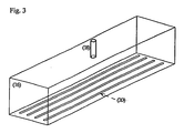
- Fig. 3 is an illustration of the electrode with slits as outlet ports.
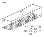
- Fig. 4 is an illustration of an arrangement and geometry of the electrode outlet ports.
- sufficient power density and frequency are applied to an electrode to create and maintain a corona discharge in a spacing between the electrode and a counterelectrode, which is preferably a moving counterelectrode.
- the power density is preferably at least 1W/cm 2 , more preferably at least 5W/cm 2 , and most preferably at least 10W/cm 2 ; and preferably not greater than 200W/cm 2 , more preferably not greater than 100W/cm 2 , and most preferably not greater than 50W/cm 2 .
- the frequency is preferably at least 2 kHz, more preferably at least 5 kHz, and most preferably at least 10 kHz; and preferably not greater than 100 kHz, more preferably not greater than 60 kHz, and most preferably not greater than 40 kHz.
- the spacing between electrode and counterelectrode is sufficient to achieve and sustain a corona discharge, preferably at least 0.1 mm, more preferably at least 1 mm, and preferably not more than 50 mm, more preferably not more than 20 mm, and most preferably not more than 10 mm.
- the counterelectrode is preferably in the form of a rotating drum preferably fitted with a dielectric sleeve, and the substrate to be coated is preferably transported along the drum.
- the terms electrode and counterelectrode are conveniently used to refer to a first electrode and a second electrode, either of which can be powered with the other being grounded.
- a mixture of gases including a balance gas and a working gas and optionally a carrier gas for the working gas (together, the total gas mixture) is flowed through the electrode, which contains at least one inlet and at least one outlet for passage of the gases, and the mixture is plasma polymerized by the corona discharge.
- the plasma polymerized mixture then forms an optically clear coating onto the moving substrate.
- working gas refers to a organosiloxane, which is a reactive substance, which may or may not be gaseous at standard temperature and pressure, that is capable of polymerizing to form a coating onto the substrate.
- suitable working gases include tetramethyldisiloxane, hexamethyldisiloxane, octamethyltrisiloxane, and tetraethylorthosilicate. Tetramethyldisiloxane is especially preferred.
- carrier gas refers to a gas, preferably an inert gas, that provides a convenient means to merge the balance gas with the working gas.
- Preferred carrier gases include nitrogen, helium, and argon.
- balance gas is a reactive or non-reactive gas that carries the working gas through the electrode and ultimately to the substrate.
- suitable balance gases include air, oxygen, CO 2, O 3 NO, nitrogen, helium, and argon, as well as combinations thereof.
- the flow rate of the total gas mixture is sufficiently high to drive the plasma polymerizing working gas to the substrate to form a contiguous film, as opposed to a powder.
- the flow rate of the total gas mixture is such that the velocity of the gas passing through the exit ports is at least 10 m/s; and not greater than 200 m/s.
- Electrode refers to a single conductive element with an inlet and an outlet or a plurality of conductive elements spaced apart to create one or more gaps for gas to flow through.
- through the electrode refers to gas flowing through the inlet and outlet of the single element or through the gaps of the multiple elements.
- control of the relative flow rates of the balance gas and the working gas which determines the concentration of working gas in the total gas mixture, also contributes to the quality of the coating formed on the substrate.
- concentration of the working gas in the total gas mixture entering the corona discharge is sufficient to create a deposit of an optically clear coating, with a minimization of gas phase nucleation. Gas phase nucleation causes granule and powder formation in the coating, which results in diminished physical properties therein, as well as equipment fouling, which leads to costly downtime.
- the concentration of the working gas in the total gas mixture depends on the nature of the working gas and the balance gas as well as the type of coating or surface modification desired, but is not less than 5 ppm, and more preferably not less than 10 ppm; and not greater than 200 ppm.
- the process is preferably carried out so that the corona discharge region is not subject to any vacuum or partial vacuum.
- the process is preferably carried out at atmospheric pressure.
- Plasma polymerization as carried out by the process of the present invention results in an optically clear coated substrate.
- optically clear is used herein to describe a coating having an optical clarity of at least 98 percent and a haze value of not greater than 2 percent, and most preferably not greater than 1 percent.
- Optical clarity is the ratio of transmitted-unscattered light to the sum of transmitted-unscattered and transmitted-scattered light ( ⁇ 2.5°).
- Haze is the ratio of transmitted-scattered light ( > 2.5°) to total transmitted light. (See, for example, ASTM D 1003-97).
- the coating can be, for example, a surface modified coating such as an adhesion promoter or an antifog coating; an optical coating such as a reflective or antireflective coating; a chemical resistant coating; or a gas barrier coating for packaging.
- the substrate used in the present invention is not limited.
- substrates include glass, metal, ceramic, paper, fabric, and plastics such as polyolefins including polyethylene and polypropylene, polystyrenes, polycarbonates, and polyesters including polyethylene terephthalate and polybutylene terephthalate.
- Fig. 1 provides an illustration of a preferred apparatus used in carrying out a preferred method of the present invention.
- working gas (10) is generated from the headspace of a contained volatile liquid (10a) and carried by a carrier gas (12) from the headspace and merged with balance gas (14) to the electrode (16).
- the carrier gas (12) and the balance gas (14) drive the working gas (10) through the electrode (16), more particularly, through at least one inlet (18) of electrode (16), and through outlets (20), which are typically in the form of slits or holes or the gaps between a plurality of conductive elements.
- Electrode (16) Power is applied to the electrode (16) to create a corona discharge (22) between the electrode (16) and the counterelectrode (24), which is a cylindrical roller preferably fitted a dielectric sleeve. It is to be understood that the electrode (16) may also or alternatively be fitted with a dielectric sleeve (not shown in the figure).
- Substrate (28) is passed continuously along the dielectric sleeve (26) and coated with plasma polymerizing working gas, which is a polymerized siloxane.
- Fig. 2 is a side view illustration of electrode (16), counterelectrode (24), and corona discharge region (22). Where the substrate is conductive, the dielectric layer (26) is positioned over the non-moving electrode (16), not the moving counterelectrode (24).
- Fig. 3 is an illustration of a preferred embodiment of the electrode outlets (20), which are in the form of parallel or substantially parallel, substantially evenly spaced slits that extend approximately the length of the electrode.
- the width of the slits is preferably not less than 0.1 mm, more preferably not less than 0.2 mm, and most preferably not less than 0.5 mm; and preferably not more than 10 mm, more preferably not more than 5 mm, and most preferably not more than 2 mm.
- Fig. 4 is an illustration of another preferred geometry and spacing of the electrode outlets (20), which are in the form of substantially circular foramina. If this geometry is used to practice the method of the present invention, the diameter of the outlets is not less than 0.05 mm, more preferably not less than 0.1 mm, and most preferably not less than 0.2 mm; and preferably not greater than 10 mm, more preferably not greater than 5 mm, and most preferably not greater than 1 mm.
- a monolithic, optically clear, contiguous coating that is powder-free or substantially powder-free can be deposited continuously on a substrate using the process of the present invention.
- the process parameters can be adjusted to form 1) a coating that renders the substrate chemically resistant (as defined by ASTM 543) to a wide variety of a) solvents, including acetone, benzene, carbon tetrachloride, diethyl ether, dimethyl formamide, ethyl acetate, ethylene dichloride, and toluene; b) acids, including as acetic acid, hydrochloric acid, hydrofluoric acid, nitric acid, and sulfuric acid; and c) bases, including ammonium hydroxide, sodium hydroxide, and phenol; 2) a coating with improved barrier to gases, including air, oxygen (O 2 GTR, ASTM D 3985), water vapor (WVTR, ASTM F 1249), and carbon dioxide (GTR, ASTM D 1434);
- the coating is prepared using the set-up substantially as illustrated in Fig. 1 .
- the counterelectrode, and power supply (fixed at 30 kHz) was obtained from Corotec Industries, Farmington, CT.
- a 5.5" long x 3" wide x 2" high electrode (14 cm x 7.5 cm x 5 cm) is designed with a single inlet port and 4 exit ports in the shape of slits as illustrated in Fig. 3 .
- the slits are each 1-mm wide and extend throughout the length of the electrode; there is a 1.5-cm separation between each slit.
- the same equipment is used in each example.
- the substrate is a Lexan polycarbonate film (obtained from General Electric) with a thickness of 7 mil (0.18 mm).
- Tetramethyldisiloxane (TMDSO) was carried in nitrogen at a concentration of 16 percent v/v and mixed with the balance gas, which is air.
- the adjusted flow rate of the TMDSO is 80 sccm and the flow rate of the balance gas is 40 scfm (1.1 x 10 6 sccm) and the concentration of TMDSO based on the total gas mixture is calculated to be 70 ppm.
- the power density of the corona discharge is 12 W/cm 2 .
- the resultant coating had a thickness of 1 ⁇ m and a chemical composition of SiO x C y H z .
- the optical clarity of the coated substrate is measured to be 99.7 percent as compared to 100 percent for the original substrate.
- the haze of the coated substrate is found to be 0.7 percent as compared to 0.6 percent for the original substrate. Both measurements were carried out in accordance with ASTM D 1003-97.
- the substrate, the working gas, the carrier gas for the working gas, the balance gas, and the balance gas flow rate, are also the same.
- the adjusted flow rate of the TMDSO is 50 sccm (45 ppm).
- the power density is 15 W/cm 2 .
- the resultant coating has a composition of SiO x C y H z and a thickness of 150 nm.
- the uncoated and coated substrates are subjected to acetone immersion for 10 minutes in accordance with ASTM 543. The uncoated substrate is found to be milky white and cracked while the coated substrate is found to be virtually unaffected.
- the substrate is a 20 g/m 2 polypropylene nonwoven.
- the working gas, carrier for the working gas, balance gas, and balance gas flow rates are the same as in the above examples.
- the adjusted flow rate of the TMDSO is 35 sccm (30 ppm)
- the power density is 5 W/cm 2
- the deposition time is 7 seconds.
- the surface energy is found to be 35 dynes/cm (3.5*10 -4 N/cm) for the untreated substrate and 52 dynes/cm (5.2*10 -4 N/cm) for the treated substrate.
- the first layer is an adhesion layer having a composition of SiO x C y H z formed using TMDSO as the working gas maintained at a flow rate of 65 sccm (60 ppm).
- the power density is set at 10 W/cm 2 and the deposition time is 10 seconds.
- the second layer is a barrier layer having the composition of SiO x formed with tetraethylorthosilicate (TEOS) as the working gas maintained at a flow rate of 15 sccm (13 ppm).
- TEOS tetraethylorthosilicate
- the power density is set at 15 W/cm 2 and the deposition time is 25 seconds.
- the oxygen gas transmission rate (O 2 GTR) of the coated and uncoated substrate are measured in accordance with ASTM D 3985.
- O 2 GTR is 32 mL/100 in 2 *day*atm (5.0*10 -7 ml/cm 2 *day*Pa) O 2 for the uncoated substrate and 0.05 mL/100 in 2 *day*atm (7.8*10 -10 ml/cm 2 *day*Pa) O 2 for the coated substrate.
Landscapes
- Chemical & Material Sciences (AREA)
- Engineering & Computer Science (AREA)
- General Chemical & Material Sciences (AREA)
- Chemical Kinetics & Catalysis (AREA)
- Materials Engineering (AREA)
- Mechanical Engineering (AREA)
- Metallurgy (AREA)
- Organic Chemistry (AREA)
- Plasma & Fusion (AREA)
- Physics & Mathematics (AREA)
- Inorganic Chemistry (AREA)
- Chemical Vapour Deposition (AREA)
- Application Of Or Painting With Fluid Materials (AREA)
- Organic Insulating Materials (AREA)
- Manufacturing Of Printed Wiring (AREA)
- Fixed Capacitors And Capacitor Manufacturing Machines (AREA)
- Surface Treatment Of Optical Elements (AREA)
- Other Resins Obtained By Reactions Not Involving Carbon-To-Carbon Unsaturated Bonds (AREA)
- Polymerisation Methods In General (AREA)
Applications Claiming Priority (5)
| Application Number | Priority Date | Filing Date | Title |
|---|---|---|---|
| US35490502P | 2002-02-05 | 2002-02-05 | |
| US354905P | 2002-02-05 | ||
| US40864002P | 2002-09-06 | 2002-09-06 | |
| US408640P | 2002-09-06 | ||
| PCT/US2003/003057 WO2003066932A1 (en) | 2002-02-05 | 2003-02-03 | Corona-generated chemical vapor deposition on a substrate |
Publications (2)
| Publication Number | Publication Date |
|---|---|
| EP1472387A1 EP1472387A1 (en) | 2004-11-03 |
| EP1472387B1 true EP1472387B1 (en) | 2008-07-23 |
Family
ID=27737478
Family Applications (1)
| Application Number | Title | Priority Date | Filing Date |
|---|---|---|---|
| EP03706031A Expired - Lifetime EP1472387B1 (en) | 2002-02-05 | 2003-02-03 | Corona-generated chemical vapor deposition on a substrate |
Country Status (8)
| Country | Link |
|---|---|
| US (1) | US6815014B2 (enExample) |
| EP (1) | EP1472387B1 (enExample) |
| JP (1) | JP4494792B2 (enExample) |
| CN (1) | CN100432289C (enExample) |
| AT (1) | ATE402277T1 (enExample) |
| AU (1) | AU2003207794A1 (enExample) |
| DE (1) | DE60322347D1 (enExample) |
| WO (1) | WO2003066932A1 (enExample) |
Cited By (1)
| Publication number | Priority date | Publication date | Assignee | Title |
|---|---|---|---|---|
| DE102019124489B3 (de) * | 2019-09-12 | 2020-11-12 | VON ARDENNE Asset GmbH & Co. KG | Vakuumanordnungen, Verfahren und Verwendung einer Elektrode im Vakuum |
Families Citing this family (39)
| Publication number | Priority date | Publication date | Assignee | Title |
|---|---|---|---|---|
| US8586149B2 (en) | 2003-06-18 | 2013-11-19 | Ford Global Technologies, Llc | Environmentally friendly reactive fixture to allow localized surface engineering for improved adhesion to coated and non-coated substrates |
| WO2005049228A2 (en) * | 2003-09-09 | 2005-06-02 | Dow Global Technologies Inc. | Glow discharge-generated chemical vapor deposition |
| DE102004029466A1 (de) * | 2004-06-18 | 2006-01-05 | Leybold Optics Gmbh | Medieninjektor |
| KR20070057200A (ko) * | 2004-09-27 | 2007-06-04 | 다우 글로벌 테크놀로지스 인크. | 플라즈마 강화 화학 기상 증착에 의한 다층 코팅 |
| EP1807548A2 (en) * | 2004-10-29 | 2007-07-18 | Dow Gloval Technologies Inc. | Abrasion resistant coatings by plasma enhanced chemical vapor deposition |
| CA2582302A1 (en) * | 2004-10-29 | 2006-05-11 | Dow Global Technologies Inc. | Improved deposition rate plasma enhanced chemical vapor process |
| US20080268252A1 (en) * | 2005-09-20 | 2008-10-30 | Juan Garces | Process for Plasma Coating a Nanocomposite Object |
| US7517561B2 (en) * | 2005-09-21 | 2009-04-14 | Ford Global Technologies, Llc | Method of coating a substrate for adhesive bonding |
| TW200814170A (en) * | 2006-09-13 | 2008-03-16 | Ind Tech Res Inst | Method of adjusting surface characteristic of a substrate |
| TWI275658B (en) * | 2006-09-13 | 2007-03-11 | Ind Tech Res Inst | Method of improving surface frame resistance of a substrate |
| CN101772588A (zh) * | 2007-07-30 | 2010-07-07 | 陶氏环球技术公司 | 大气压等离子体增强化学气相沉积方法 |
| KR100962044B1 (ko) * | 2007-12-06 | 2010-06-08 | 성균관대학교산학협력단 | 저유전 플라즈마 중합체 박막 및 그 제조 방법 |
| JP2012517529A (ja) * | 2009-02-12 | 2012-08-02 | フジフィルム・マニュファクチュアリング・ヨーロッパ・ベスローテン・フエンノートシャップ | ポリマー基材上の2層バリヤー |
| US7985188B2 (en) | 2009-05-13 | 2011-07-26 | Cv Holdings Llc | Vessel, coating, inspection and processing apparatus |
| DK2251454T3 (da) | 2009-05-13 | 2014-10-13 | Sio2 Medical Products Inc | Coating og inspektion af beholder |
| DE102009030303A1 (de) * | 2009-06-24 | 2010-12-30 | Fraunhofer-Gesellschaft zur Förderung der angewandten Forschung e.V. | Verfahren zur Herstellung von Antireflexschicht-bildenden Beschichtungen sowie Antireflexbeschichtungen |
| US9458536B2 (en) | 2009-07-02 | 2016-10-04 | Sio2 Medical Products, Inc. | PECVD coating methods for capped syringes, cartridges and other articles |
| US9488927B2 (en) | 2010-04-30 | 2016-11-08 | Hewlett-Packard Development Company, L.P. | Printing systems and methods of using such printing systems |
| US11624115B2 (en) | 2010-05-12 | 2023-04-11 | Sio2 Medical Products, Inc. | Syringe with PECVD lubrication |
| US9878101B2 (en) | 2010-11-12 | 2018-01-30 | Sio2 Medical Products, Inc. | Cyclic olefin polymer vessels and vessel coating methods |
| US9272095B2 (en) | 2011-04-01 | 2016-03-01 | Sio2 Medical Products, Inc. | Vessels, contact surfaces, and coating and inspection apparatus and methods |
| EP2589366A1 (de) * | 2011-11-07 | 2013-05-08 | IDT Biologika GmbH | Biologisch abbaubare Folienverpackung für orale Biologika |
| AU2012318242A1 (en) | 2011-11-11 | 2013-05-30 | Sio2 Medical Products, Inc. | Passivation, pH protective or lubricity coating for pharmaceutical package, coating process and apparatus |
| US11116695B2 (en) | 2011-11-11 | 2021-09-14 | Sio2 Medical Products, Inc. | Blood sample collection tube |
| US8945418B2 (en) * | 2011-11-16 | 2015-02-03 | The United States Of America, As Represented By The Secretary Of The Navy | Melt stabilization and vapor-phase synthesis of cesium germanium halides |
| EP2846755A1 (en) | 2012-05-09 | 2015-03-18 | SiO2 Medical Products, Inc. | Saccharide protective coating for pharmaceutical package |
| US20150297800A1 (en) | 2012-07-03 | 2015-10-22 | Sio2 Medical Products, Inc. | SiOx BARRIER FOR PHARMACEUTICAL PACKAGE AND COATING PROCESS |
| CA2890066C (en) | 2012-11-01 | 2021-11-09 | Sio2 Medical Products, Inc. | Coating inspection method |
| WO2014078666A1 (en) | 2012-11-16 | 2014-05-22 | Sio2 Medical Products, Inc. | Method and apparatus for detecting rapid barrier coating integrity characteristics |
| US9764093B2 (en) | 2012-11-30 | 2017-09-19 | Sio2 Medical Products, Inc. | Controlling the uniformity of PECVD deposition |
| EP2925903B1 (en) | 2012-11-30 | 2022-04-13 | Si02 Medical Products, Inc. | Controlling the uniformity of pecvd deposition on medical syringes, cartridges, and the like |
| EP2961858B1 (en) | 2013-03-01 | 2022-09-07 | Si02 Medical Products, Inc. | Coated syringe. |
| US9937099B2 (en) | 2013-03-11 | 2018-04-10 | Sio2 Medical Products, Inc. | Trilayer coated pharmaceutical packaging with low oxygen transmission rate |
| CN105392916B (zh) | 2013-03-11 | 2019-03-08 | Sio2医药产品公司 | 涂布包装材料 |
| EP2971227B1 (en) | 2013-03-15 | 2017-11-15 | Si02 Medical Products, Inc. | Coating method. |
| EP2896502B1 (en) * | 2014-01-16 | 2017-03-08 | ThyssenKrupp Steel Europe AG | Composite sheet and method of manufacturing |
| EP3693493A1 (en) | 2014-03-28 | 2020-08-12 | SiO2 Medical Products, Inc. | Antistatic coatings for plastic vessels |
| US11077233B2 (en) | 2015-08-18 | 2021-08-03 | Sio2 Medical Products, Inc. | Pharmaceutical and other packaging with low oxygen transmission rate |
| US12129078B2 (en) * | 2021-03-04 | 2024-10-29 | Yeti Coolers, Llc | Surface coating of drinkware |
Family Cites Families (17)
| Publication number | Priority date | Publication date | Assignee | Title |
|---|---|---|---|---|
| US424103A (en) * | 1890-03-25 | Steam-generator | ||
| DE3705482A1 (de) * | 1987-02-20 | 1988-09-01 | Hoechst Ag | Verfahren und anordnung zur oberflaechenvorbehandlung von kunststoff mittels einer elektrischen koronaentladung |
| GB8713986D0 (en) * | 1987-06-16 | 1987-07-22 | Shell Int Research | Apparatus for plasma surface treating |
| NL8701530A (nl) * | 1987-06-30 | 1989-01-16 | Stichting Fund Ond Material | Werkwijze voor het behandelen van oppervlakken van substraten met behulp van een plasma en reactor voor het uitvoeren van die werkwijze. |
| US4894352A (en) | 1988-10-26 | 1990-01-16 | Texas Instruments Inc. | Deposition of silicon-containing films using organosilicon compounds and nitrogen trifluoride |
| US5176938A (en) * | 1988-11-23 | 1993-01-05 | Plasmacarb Inc. | Process for surface treatment of pulverulent material |
| US5194291A (en) * | 1991-04-22 | 1993-03-16 | General Atomics | Corona discharge treatment |
| DE4225106C2 (de) * | 1992-07-30 | 1995-10-05 | Heraeus Kulzer Gmbh | Verfahren und Vorrichtung zur Herstellung eines Metall-Kunststoff-Verbundes |
| KR960000190B1 (ko) | 1992-11-09 | 1996-01-03 | 엘지전자주식회사 | 반도체 제조방법 및 그 장치 |
| FR2704558B1 (fr) * | 1993-04-29 | 1995-06-23 | Air Liquide | Procede et dispositif pour creer un depot d'oxyde de silicium sur un substrat solide en defilement. |
| US5456972A (en) * | 1993-05-28 | 1995-10-10 | The University Of Tennessee Research Corporation | Method and apparatus for glow discharge plasma treatment of polymer materials at atmospheric pressure |
| US6083355A (en) * | 1997-07-14 | 2000-07-04 | The University Of Tennessee Research Corporation | Electrodes for plasma treater systems |
| US6106659A (en) * | 1997-07-14 | 2000-08-22 | The University Of Tennessee Research Corporation | Treater systems and methods for generating moderate-to-high-pressure plasma discharges for treating materials and related treated materials |
| EP0995218A1 (en) * | 1997-07-14 | 2000-04-26 | The University Of Tennessee Research Corporation | Plasma treater systems and treatment methods |
| US6082292A (en) * | 1999-01-05 | 2000-07-04 | Wisconsin Alumni Research Foundation | Sealing roller system for surface treatment gas reactors |
| US6118218A (en) * | 1999-02-01 | 2000-09-12 | Sigma Technologies International, Inc. | Steady-state glow-discharge plasma at atmospheric pressure |
| WO2000070117A1 (en) * | 1999-05-14 | 2000-11-23 | The Regents Of The University Of California | Low-temperature compatible wide-pressure-range plasma flow device |
-
2003
- 2003-02-03 AT AT03706031T patent/ATE402277T1/de not_active IP Right Cessation
- 2003-02-03 US US10/357,019 patent/US6815014B2/en not_active Expired - Lifetime
- 2003-02-03 EP EP03706031A patent/EP1472387B1/en not_active Expired - Lifetime
- 2003-02-03 WO PCT/US2003/003057 patent/WO2003066932A1/en not_active Ceased
- 2003-02-03 AU AU2003207794A patent/AU2003207794A1/en not_active Abandoned
- 2003-02-03 JP JP2003566273A patent/JP4494792B2/ja not_active Expired - Lifetime
- 2003-02-03 CN CNB038033178A patent/CN100432289C/zh not_active Expired - Fee Related
- 2003-02-03 DE DE60322347T patent/DE60322347D1/de not_active Expired - Lifetime
Cited By (1)
| Publication number | Priority date | Publication date | Assignee | Title |
|---|---|---|---|---|
| DE102019124489B3 (de) * | 2019-09-12 | 2020-11-12 | VON ARDENNE Asset GmbH & Co. KG | Vakuumanordnungen, Verfahren und Verwendung einer Elektrode im Vakuum |
Also Published As
| Publication number | Publication date |
|---|---|
| EP1472387A1 (en) | 2004-11-03 |
| WO2003066932A1 (en) | 2003-08-14 |
| HK1072279A1 (en) | 2005-08-19 |
| CN100432289C (zh) | 2008-11-12 |
| AU2003207794A1 (en) | 2003-09-02 |
| JP2005533174A (ja) | 2005-11-04 |
| US6815014B2 (en) | 2004-11-09 |
| US20040091637A1 (en) | 2004-05-13 |
| ATE402277T1 (de) | 2008-08-15 |
| JP4494792B2 (ja) | 2010-06-30 |
| CN1628187A (zh) | 2005-06-15 |
| DE60322347D1 (de) | 2008-09-04 |
Similar Documents
| Publication | Publication Date | Title |
|---|---|---|
| EP1472387B1 (en) | Corona-generated chemical vapor deposition on a substrate | |
| AU666675B2 (en) | Apparatus for rapid plasma treatments and method | |
| JP3488458B2 (ja) | 物品のための保護フィルム及び方法 | |
| US5494712A (en) | Method of forming a plasma polymerized film | |
| US20080095954A1 (en) | Multilayer Coatings By Plasma Enhanced Chemical Vapor Deposition | |
| KR101043792B1 (ko) | 이산화티탄의 증착 방법 및 기판 | |
| JP2001295051A (ja) | 材料の表面処理または被覆方法 | |
| JP2008516089A (ja) | プラズマコーティング方法 | |
| US20080107820A1 (en) | Deposition Rate Plasma Enhanced Chemical Vapor Process | |
| US20030049468A1 (en) | Cascade arc plasma and abrasion resistant coatings made therefrom | |
| US20060222779A1 (en) | Glow discharge-generated chemical vapor deposition | |
| HK1072279B (en) | Corona-generated chemical vapor deposition on a substrate | |
| US4776298A (en) | Apparatus for performing a plasma enhanced chemical vapor deposition on an edge of a polycarbonate sheet | |
| Bushnell-Watson et al. | The chemistry of thin film deposits formed from hexamethyldisiloxane and hexamethyldisilazane plasmas. | |
| Yu | Plasma deposition and treatment by a low-temperature cascade arc torch |
Legal Events
| Date | Code | Title | Description |
|---|---|---|---|
| PUAI | Public reference made under article 153(3) epc to a published international application that has entered the european phase |
Free format text: ORIGINAL CODE: 0009012 |
|
| 17P | Request for examination filed |
Effective date: 20040803 |
|
| AK | Designated contracting states |
Kind code of ref document: A1 Designated state(s): AT BE BG CH CY CZ DE DK EE ES FI FR GB GR HU IE IT LI LU MC NL PT SE SI SK TR |
|
| AX | Request for extension of the european patent |
Extension state: AL LT LV MK RO |
|
| 17Q | First examination report despatched |
Effective date: 20041213 |
|
| REG | Reference to a national code |
Ref country code: HK Ref legal event code: DE Ref document number: 1072279 Country of ref document: HK |
|
| GRAP | Despatch of communication of intention to grant a patent |
Free format text: ORIGINAL CODE: EPIDOSNIGR1 |
|
| GRAS | Grant fee paid |
Free format text: ORIGINAL CODE: EPIDOSNIGR3 |
|
| GRAA | (expected) grant |
Free format text: ORIGINAL CODE: 0009210 |
|
| AK | Designated contracting states |
Kind code of ref document: B1 Designated state(s): AT BE BG CH CY CZ DE DK EE ES FI FR GB GR HU IE IT LI LU MC NL PT SE SI SK TR |
|
| REG | Reference to a national code |
Ref country code: GB Ref legal event code: FG4D |
|
| REG | Reference to a national code |
Ref country code: CH Ref legal event code: EP |
|
| REG | Reference to a national code |
Ref country code: IE Ref legal event code: FG4D |
|
| REF | Corresponds to: |
Ref document number: 60322347 Country of ref document: DE Date of ref document: 20080904 Kind code of ref document: P |
|
| NLV1 | Nl: lapsed or annulled due to failure to fulfill the requirements of art. 29p and 29m of the patents act | ||
| PG25 | Lapsed in a contracting state [announced via postgrant information from national office to epo] |
Ref country code: ES Free format text: LAPSE BECAUSE OF FAILURE TO SUBMIT A TRANSLATION OF THE DESCRIPTION OR TO PAY THE FEE WITHIN THE PRESCRIBED TIME-LIMIT Effective date: 20081103 Ref country code: PT Free format text: LAPSE BECAUSE OF FAILURE TO SUBMIT A TRANSLATION OF THE DESCRIPTION OR TO PAY THE FEE WITHIN THE PRESCRIBED TIME-LIMIT Effective date: 20081223 Ref country code: NL Free format text: LAPSE BECAUSE OF FAILURE TO SUBMIT A TRANSLATION OF THE DESCRIPTION OR TO PAY THE FEE WITHIN THE PRESCRIBED TIME-LIMIT Effective date: 20080723 |
|
| PG25 | Lapsed in a contracting state [announced via postgrant information from national office to epo] |
Ref country code: SI Free format text: LAPSE BECAUSE OF FAILURE TO SUBMIT A TRANSLATION OF THE DESCRIPTION OR TO PAY THE FEE WITHIN THE PRESCRIBED TIME-LIMIT Effective date: 20080723 Ref country code: BG Free format text: LAPSE BECAUSE OF FAILURE TO SUBMIT A TRANSLATION OF THE DESCRIPTION OR TO PAY THE FEE WITHIN THE PRESCRIBED TIME-LIMIT Effective date: 20081023 Ref country code: AT Free format text: LAPSE BECAUSE OF FAILURE TO SUBMIT A TRANSLATION OF THE DESCRIPTION OR TO PAY THE FEE WITHIN THE PRESCRIBED TIME-LIMIT Effective date: 20080723 Ref country code: FI Free format text: LAPSE BECAUSE OF FAILURE TO SUBMIT A TRANSLATION OF THE DESCRIPTION OR TO PAY THE FEE WITHIN THE PRESCRIBED TIME-LIMIT Effective date: 20080723 |
|
| PG25 | Lapsed in a contracting state [announced via postgrant information from national office to epo] |
Ref country code: BE Free format text: LAPSE BECAUSE OF FAILURE TO SUBMIT A TRANSLATION OF THE DESCRIPTION OR TO PAY THE FEE WITHIN THE PRESCRIBED TIME-LIMIT Effective date: 20080723 |
|
| REG | Reference to a national code |
Ref country code: HK Ref legal event code: GR Ref document number: 1072279 Country of ref document: HK |
|
| PG25 | Lapsed in a contracting state [announced via postgrant information from national office to epo] |
Ref country code: DK Free format text: LAPSE BECAUSE OF FAILURE TO SUBMIT A TRANSLATION OF THE DESCRIPTION OR TO PAY THE FEE WITHIN THE PRESCRIBED TIME-LIMIT Effective date: 20080723 Ref country code: EE Free format text: LAPSE BECAUSE OF FAILURE TO SUBMIT A TRANSLATION OF THE DESCRIPTION OR TO PAY THE FEE WITHIN THE PRESCRIBED TIME-LIMIT Effective date: 20080723 |
|
| PG25 | Lapsed in a contracting state [announced via postgrant information from national office to epo] |
Ref country code: SK Free format text: LAPSE BECAUSE OF FAILURE TO SUBMIT A TRANSLATION OF THE DESCRIPTION OR TO PAY THE FEE WITHIN THE PRESCRIBED TIME-LIMIT Effective date: 20080723 Ref country code: CZ Free format text: LAPSE BECAUSE OF FAILURE TO SUBMIT A TRANSLATION OF THE DESCRIPTION OR TO PAY THE FEE WITHIN THE PRESCRIBED TIME-LIMIT Effective date: 20080723 |
|
| PLBE | No opposition filed within time limit |
Free format text: ORIGINAL CODE: 0009261 |
|
| STAA | Information on the status of an ep patent application or granted ep patent |
Free format text: STATUS: NO OPPOSITION FILED WITHIN TIME LIMIT |
|
| 26N | No opposition filed |
Effective date: 20090424 |
|
| PG25 | Lapsed in a contracting state [announced via postgrant information from national office to epo] |
Ref country code: IT Free format text: LAPSE BECAUSE OF FAILURE TO SUBMIT A TRANSLATION OF THE DESCRIPTION OR TO PAY THE FEE WITHIN THE PRESCRIBED TIME-LIMIT Effective date: 20080723 |
|
| PG25 | Lapsed in a contracting state [announced via postgrant information from national office to epo] |
Ref country code: MC Free format text: LAPSE BECAUSE OF NON-PAYMENT OF DUE FEES Effective date: 20090228 |
|
| REG | Reference to a national code |
Ref country code: CH Ref legal event code: PL |
|
| PG25 | Lapsed in a contracting state [announced via postgrant information from national office to epo] |
Ref country code: CH Free format text: LAPSE BECAUSE OF NON-PAYMENT OF DUE FEES Effective date: 20090228 Ref country code: LI Free format text: LAPSE BECAUSE OF NON-PAYMENT OF DUE FEES Effective date: 20090228 |
|
| REG | Reference to a national code |
Ref country code: IE Ref legal event code: MM4A |
|
| PG25 | Lapsed in a contracting state [announced via postgrant information from national office to epo] |
Ref country code: IE Free format text: LAPSE BECAUSE OF NON-PAYMENT OF DUE FEES Effective date: 20090203 Ref country code: SE Free format text: LAPSE BECAUSE OF FAILURE TO SUBMIT A TRANSLATION OF THE DESCRIPTION OR TO PAY THE FEE WITHIN THE PRESCRIBED TIME-LIMIT Effective date: 20081023 |
|
| PG25 | Lapsed in a contracting state [announced via postgrant information from national office to epo] |
Ref country code: GR Free format text: LAPSE BECAUSE OF FAILURE TO SUBMIT A TRANSLATION OF THE DESCRIPTION OR TO PAY THE FEE WITHIN THE PRESCRIBED TIME-LIMIT Effective date: 20081024 |
|
| PG25 | Lapsed in a contracting state [announced via postgrant information from national office to epo] |
Ref country code: LU Free format text: LAPSE BECAUSE OF NON-PAYMENT OF DUE FEES Effective date: 20090203 |
|
| PG25 | Lapsed in a contracting state [announced via postgrant information from national office to epo] |
Ref country code: HU Free format text: LAPSE BECAUSE OF FAILURE TO SUBMIT A TRANSLATION OF THE DESCRIPTION OR TO PAY THE FEE WITHIN THE PRESCRIBED TIME-LIMIT Effective date: 20090124 |
|
| PG25 | Lapsed in a contracting state [announced via postgrant information from national office to epo] |
Ref country code: TR Free format text: LAPSE BECAUSE OF FAILURE TO SUBMIT A TRANSLATION OF THE DESCRIPTION OR TO PAY THE FEE WITHIN THE PRESCRIBED TIME-LIMIT Effective date: 20080723 |
|
| PG25 | Lapsed in a contracting state [announced via postgrant information from national office to epo] |
Ref country code: CY Free format text: LAPSE BECAUSE OF FAILURE TO SUBMIT A TRANSLATION OF THE DESCRIPTION OR TO PAY THE FEE WITHIN THE PRESCRIBED TIME-LIMIT Effective date: 20080723 |
|
| REG | Reference to a national code |
Ref country code: FR Ref legal event code: PLFP Year of fee payment: 14 |
|
| REG | Reference to a national code |
Ref country code: FR Ref legal event code: PLFP Year of fee payment: 15 |
|
| REG | Reference to a national code |
Ref country code: FR Ref legal event code: PLFP Year of fee payment: 16 |
|
| PGFP | Annual fee paid to national office [announced via postgrant information from national office to epo] |
Ref country code: FR Payment date: 20181213 Year of fee payment: 17 |
|
| PGFP | Annual fee paid to national office [announced via postgrant information from national office to epo] |
Ref country code: GB Payment date: 20190130 Year of fee payment: 17 Ref country code: DE Payment date: 20190122 Year of fee payment: 17 |
|
| REG | Reference to a national code |
Ref country code: DE Ref legal event code: R119 Ref document number: 60322347 Country of ref document: DE |
|
| GBPC | Gb: european patent ceased through non-payment of renewal fee |
Effective date: 20200203 |
|
| PG25 | Lapsed in a contracting state [announced via postgrant information from national office to epo] |
Ref country code: FR Free format text: LAPSE BECAUSE OF NON-PAYMENT OF DUE FEES Effective date: 20200229 Ref country code: DE Free format text: LAPSE BECAUSE OF NON-PAYMENT OF DUE FEES Effective date: 20200901 Ref country code: GB Free format text: LAPSE BECAUSE OF NON-PAYMENT OF DUE FEES Effective date: 20200203 |