EP1471749A1 - Concentrateur de câblage, unité de distribution des signaux le comportant et coffret comportant cette unité - Google Patents
Concentrateur de câblage, unité de distribution des signaux le comportant et coffret comportant cette unité Download PDFInfo
- Publication number
- EP1471749A1 EP1471749A1 EP04291066A EP04291066A EP1471749A1 EP 1471749 A1 EP1471749 A1 EP 1471749A1 EP 04291066 A EP04291066 A EP 04291066A EP 04291066 A EP04291066 A EP 04291066A EP 1471749 A1 EP1471749 A1 EP 1471749A1
- Authority
- EP
- European Patent Office
- Prior art keywords
- connector
- connection terminal
- cable
- concentrator according
- receive
- Prior art date
- Legal status (The legal status is an assumption and is not a legal conclusion. Google has not performed a legal analysis and makes no representation as to the accuracy of the status listed.)
- Granted
Links
- 238000009826 distribution Methods 0.000 title claims description 41
- 238000012545 processing Methods 0.000 claims abstract description 5
- 239000000758 substrate Substances 0.000 claims description 6
- 239000007769 metal material Substances 0.000 claims description 3
- 239000004020 conductor Substances 0.000 description 13
- 238000009434 installation Methods 0.000 description 12
- 238000012550 audit Methods 0.000 description 11
- 235000021183 entrée Nutrition 0.000 description 6
- 238000010586 diagram Methods 0.000 description 4
- 230000002349 favourable effect Effects 0.000 description 3
- 239000002184 metal Substances 0.000 description 3
- 229910052751 metal Inorganic materials 0.000 description 3
- 238000012360 testing method Methods 0.000 description 3
- 230000003313 weakening effect Effects 0.000 description 3
- 101100536354 Drosophila melanogaster tant gene Proteins 0.000 description 2
- 239000000463 material Substances 0.000 description 2
- 230000002265 prevention Effects 0.000 description 2
- 230000001902 propagating effect Effects 0.000 description 2
- 230000004224 protection Effects 0.000 description 2
- 240000008042 Zea mays Species 0.000 description 1
- 230000006978 adaptation Effects 0.000 description 1
- 238000004891 communication Methods 0.000 description 1
- 230000006854 communication Effects 0.000 description 1
- 230000008878 coupling Effects 0.000 description 1
- 238000010168 coupling process Methods 0.000 description 1
- 238000005859 coupling reaction Methods 0.000 description 1
- 235000013305 food Nutrition 0.000 description 1
- 230000001965 increasing effect Effects 0.000 description 1
- 238000012423 maintenance Methods 0.000 description 1
- 230000000873 masking effect Effects 0.000 description 1
- 210000000056 organ Anatomy 0.000 description 1
- 230000000644 propagated effect Effects 0.000 description 1
- 230000000717 retained effect Effects 0.000 description 1
- 230000035945 sensitivity Effects 0.000 description 1
- 230000007704 transition Effects 0.000 description 1
Images


Classifications
-
- B—PERFORMING OPERATIONS; TRANSPORTING
- B41—PRINTING; LINING MACHINES; TYPEWRITERS; STAMPS
- B41J—TYPEWRITERS; SELECTIVE PRINTING MECHANISMS, i.e. MECHANISMS PRINTING OTHERWISE THAN FROM A FORME; CORRECTION OF TYPOGRAPHICAL ERRORS
- B41J35/00—Other apparatus or arrangements associated with, or incorporated in, ink-ribbon mechanisms
- B41J35/04—Ink-ribbon guides
-
- H—ELECTRICITY
- H04—ELECTRIC COMMUNICATION TECHNIQUE
- H04Q—SELECTING
- H04Q1/00—Details of selecting apparatus or arrangements
- H04Q1/02—Constructional details
- H04Q1/10—Exchange station construction
-
- H—ELECTRICITY
- H04—ELECTRIC COMMUNICATION TECHNIQUE
- H04Q—SELECTING
- H04Q1/00—Details of selecting apparatus or arrangements
- H04Q1/02—Constructional details
- H04Q1/025—Cabinets
-
- H—ELECTRICITY
- H04—ELECTRIC COMMUNICATION TECHNIQUE
- H04Q—SELECTING
- H04Q1/00—Details of selecting apparatus or arrangements
- H04Q1/02—Constructional details
- H04Q1/03—Power distribution arrangements
-
- H—ELECTRICITY
- H04—ELECTRIC COMMUNICATION TECHNIQUE
- H04Q—SELECTING
- H04Q1/00—Details of selecting apparatus or arrangements
- H04Q1/02—Constructional details
- H04Q1/14—Distribution frames
- H04Q1/142—Terminal blocks for distribution frames
-
- B—PERFORMING OPERATIONS; TRANSPORTING
- B41—PRINTING; LINING MACHINES; TYPEWRITERS; STAMPS
- B41J—TYPEWRITERS; SELECTIVE PRINTING MECHANISMS, i.e. MECHANISMS PRINTING OTHERWISE THAN FROM A FORME; CORRECTION OF TYPOGRAPHICAL ERRORS
- B41J19/00—Character- or line-spacing mechanisms
-
- H—ELECTRICITY
- H04—ELECTRIC COMMUNICATION TECHNIQUE
- H04Q—SELECTING
- H04Q1/00—Details of selecting apparatus or arrangements
- H04Q1/02—Constructional details
- H04Q1/028—Subscriber network interface devices
-
- H—ELECTRICITY
- H04—ELECTRIC COMMUNICATION TECHNIQUE
- H04Q—SELECTING
- H04Q2201/00—Constructional details of selecting arrangements
- H04Q2201/10—Housing details
-
- H—ELECTRICITY
- H04—ELECTRIC COMMUNICATION TECHNIQUE
- H04Q—SELECTING
- H04Q2201/00—Constructional details of selecting arrangements
- H04Q2201/12—Printed circuits
-
- H—ELECTRICITY
- H04—ELECTRIC COMMUNICATION TECHNIQUE
- H04Q—SELECTING
- H04Q2201/00—Constructional details of selecting arrangements
- H04Q2201/16—Coaxial cable connectors
-
- H—ELECTRICITY
- H04—ELECTRIC COMMUNICATION TECHNIQUE
- H04Q—SELECTING
- H04Q2201/00—Constructional details of selecting arrangements
- H04Q2201/80—Constructional details of selecting arrangements in specific systems
- H04Q2201/802—Constructional details of selecting arrangements in specific systems in data transmission systems
Definitions
- chassis on which said printed circuit board is mounted, each said first, second and third connection terminal as well as each said first, second and third connector, which chassis has a housing for each said active electronic unit.
- the wiring concentrator according to the invention makes it possible to have signals on each of the third connection terminals available on the first connector, on the second connector and on the third connector, which connectors respectively have signals present on the first connection terminal, on the second connection terminal connection and on each third connection terminal.
- the wiring concentrator according to the invention thus offers the possibility to have on each cable received in a third connection terminal, signals of different kinds arriving at the wiring concentrator through the first connection terminal, by the second connection terminal and by the third connection terminals and processed by active electronic units intended to be received respectively in the first connector, the second connector and the third connector.
- connection terminals and connectors Providing a printed circuit board to operate the different connections between connection terminals and connectors allows to carry out in a particularly simple, convenient and economical way the material realization of these connections while respecting the protection requirements against weakening and / or disturbance of signals.
- connectors to receive the units active electronics and specializing each of these connectors by type of signal is particularly advantageous for the installer and / or the user of the signal distribution facility to which the wiring concentrator, in particular with regard to maintenance and / or scalability.
- said second connector is the closest to said first end while said third connector is disposed between said first connector and said second connector.
- the invention also relates, in a second aspect, to a unit of distribution comprising a wiring concentrator as described above and at least one of an active electronic signal processing unit television, an active electronic telephony unit and a unit active electronics of local computer network arranged in a said housing of said chassis and received in a respective one of said first connector, second connector and third connector.
- the invention also aims, for convenience and simplicity of implementation work, in particular in the technical sheath of a building, a box for signal distribution installation, comprising at least one signal unit signal distribution as described above and a power supply unit direct current.
- this box also includes a patch panel and / or at least one test telephone jack.
- the signal distribution installation 10 illustrated in FIG. 1 comprises a box 11 to which a coaxial cable 12 for distributing television signals, a cable 13 for connection to the telephone network public switched and eight cables 14A to 14H of local computer network.
- Installation 10 is part of a residential or tertiary building, with here the box 11 which is arranged in the technical sheath of this building.
- the coaxial cable 12 for the distribution of television signals is connected to a coupler itself connected, on the one hand, to a reception antenna or to a cable network for the distribution of terrestrial broadcasts and, secondly, to a antenna for receiving satellite broadcasts.
- the telephone cable 13 has two pairs of conductors. II is connected to a central office of the telephone operator, which provides a line on each of the two pairs of cable 13.
- the local computer network cables 14A to 14H are each of the conventional type with four pairs of twisted conductors, here in category 6. These cables each run through the building to which they belong installation 10, between the box 11 and a socket 15, here of the RJ 45 type category 6.
- Each of the cables 14A to 14H is intended to distribute not only local computer network signals and signals from telephony, but also television signals.
- FIG. 1 shows the wiring of the sockets 15.
- the pair of contacts 1 and 2 is provided for signals local computer network LAN, the same goes for the pair of contacts 3 and 6, that the pair of contacts 4 and 5 is provided for the signals of PHONE telephony and that the pair of contacts 7 and 8 is provided for TV television signals.
- an adapter is connected to socket 15 and a coaxial cable is connected between the adapter and the television.
- the coaxial cable and the adapter are combined in a same cord.
- This adapter includes a converter to transform the signal symmetrical present on the twisted pair of conductors leading to contacts 7 and 8 of socket 15 in an asymmetrical signal which can be conveyed by the coaxial cable.
- box 11 includes a unit active electronics 16 for television signal processing, one unit active electronics 17 of local computer network and an electronic unit active 18 for telephony, with cable 12 which is connected to unit 16, with cable 13 which is connected to the unit 18 and with each of the cables 14A to 14H which is connected to each of units 16, 17 and 18.
- a coaxial cable 19 for distributing television signals a cable coaxial 20 for connection to a modulator producing signals terrestrial television and telephone cable 21.
- Cables 19 and 20 are each connected to a splitter-coupler (not shown) as part of a printed circuit board which, as we will see more far, belongs to a cabling concentrator that contains the box 11.
- This splitter-coupler has two inputs connected respectively to cable 12 and to the cable 20 and two outputs connected respectively to the unit 16 and to the cable 19.
- the telephone cable 21 is of the same type as the cable 13, that is to say that it has two pairs of conductors.
- the connection between cables 13 and 21 is carried out via the aforementioned printed circuit board: this connects each of the four conductors of the cable 13 to the connector 52 and to the socket 47.
- the cable 22 is connected to a conventional telephone socket (not represented) where are present the two lines each conveyed by one of pairs of conductors for cable 13 and cable 21.
- a label holder 34 with eight housings, is provided for identifying the location of the sockets 15 to each of which leads one of the cables 14A at 14h.
- a similar label holder 35 is provided next to the label holder 34.
- the box 11 is designed to accommodate, if it is desires, in addition to the signal distribution unit comprising the units active electronics 16, 17 and 18, a second similar distribution unit.
- the shutter 31 is removed to reveal the front faces active electronic units of the second signal distribution unit while the label holder 35 is used to identify the location at which terminate the eight additional local computer network cables connected to the second signal distribution unit.
- the cabinet 11 has a frame metal 36 secured to the base 25.
- a power supply unit 37 continuous On the chassis 36 are mounted a power supply unit 37 continuous, support 38 for test telephone sockets 39, unit for signal distribution 40 and a patch panel 41 having sockets in RJ 45 format in category 6.
- the chassis 36 is designed to receive, if desired, in order to perform an extension of installation 10, a second signal distribution unit such as 40 and a second patch panel such as 41.
- the location reception of the second signal distribution unit is visible on the figure 4 to the right of unit 40 while the location for the second patch panel is visible in Figure 4 below panel 41.
- Unit 40 includes active electronic units 16, 17 and 18 and a cable concentrator 42.
- the concentrator 42 comprises at the bottom three plugs F 43, 44 and 45, two sockets 46 and 47 in RJ 45 format in category 6 and one terminal block 48 to six screw connection sockets (see Figure 6).
- the plugs 43 to 45 respectively receive the coaxial cable 12, the coaxial 19 and the coaxial cable 20.
- Socket 46 receives, if desired, a computer network cable from patch cord type for cascading unit 40 with another unit 40 for telephony and network signals local IT: the wiring of the contacts of socket 46 is similar to that sockets 15 except that the pair of contacts 7 and 8 is provided for telephone (not television) signals.
- Printed circuit board present in the concentrator 42 connects contacts 1, 2, 3 and 6 to the unit electronics 17 and each of contacts 4, 5, 7 and 8 to a respective conductor of the cable 13.
- plug 44 of that of two units 40 which receives cable 12 is connected to one end of a coaxial cable, the other end is connected to the plug 43 of the other unit 40 while the cable 19 is connected to plug 44 of this other unit.
- the socket 47 receives the telephone cable 21.
- Terminal block 48 in four of its screw connection cells, receives the telephone cable conductors 13.
- the other two cells of screw connection of terminal block 48 receive a current supply cable continuous connected to unit 37.
- the telephone cable 13 passes through the sockets 39.
- the concentrator 42 has eight outlets 49A to 49H in RJ 45 format, here in category 6.
- the sockets 49A to 49H each receive the end of a cord of patch 49 ′ (FIG. 7) the other end of which is received in one of the sockets of the panel 41.
- Each of the cables 14A to 14H is connected to one of the sockets on the patch panel 41.
- each of the cables 14A to 14H is connected to one sockets 49A to 49H via patch panel 41 and a 49 'patch cord.
- the concentrator 42 still has three connectors 50, 51 and 52 each receiving a connection plug respectively from unit 16, from unit 17 and unit 18, as seen more particularly in FIG. 8.
- the plugs, sockets, terminal blocks and connectors which are connected to the card 53, as well as the latter, are mounted on a metal frame 54 which envelops the card 53 and which is provided with a projecting annular nose 55 with section rectangular surrounding the connectors 50 to 52.
- the nose 55 forms three housings 56, 57 and 58 to receive unit 16, unit 17 and unit 18.
- Each of these units has a metal case inside which has an electronic card, respectively 60, 61 and 62 (figures 8).
- Air holes are provided in each of the unit boxes 16, 17 and 18 and corresponding windows are provided on the nose 55.
- the rear end of the printed circuit board electronic card of each of units 16, 17 and 18 forms a card which is received in the corresponding connector 50, 51 or 52.
- the printed circuit board 53 is used to connect plug 43 to the active electronic unit 16, to connect the two telephone pairs connected to terminal block 48 to the active electronic unit 18 and to be connected each from sockets 46 and 49A to 49H to the active electronic unit 17 and each of the sockets 49A to 49H at active electronic units 16 and 18.
- the map 53 has four superimposed layers 65 to 68 each comprising a dielectric substrate and tracks or blocks of metallic material conductor arranged on the substrate.
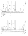
- the general path of the telephone signals is represented by line 69 in long broken lines
- the path of the signals local computer network corresponding to one of the pairs of conductors twisted is represented by line 70 in short dashed lines while the signal path corresponding to the other pair is represented by line 71 in dashed line.
- the path 69 of the telephone signals passes essentially in layer 65, which is the rearmost, that is to say that which is furthest from plugs, sockets, terminal blocks and connectors 43 to 48, 49A at 49H and 50 at 52.
- Vias are used to pass these signals through others layers, respectively, from back to front, 66, 67 and 68, at the terminal block 48 and sockets 46 and 47, at connector 52 and at taken 49A to 49H.
- Local computer network signals whose route is materialized by lines 71 and 70 take mainly the layer respectively intermediate 66 and the intermediate layer 67. Vias practiced for the transition of these signals through layer 68 and possibly the layer 67 are provided at the socket 46, at the connector 51 and at the sockets 49A to 49H.
- the active electronic unit 18 is used, for each of the sockets 49A to 49H, thanks to the push buttons 72 which it has eight fronts, select the one of the two lines provided by cable 13 which will be present on the pair of contacts 4 and 5 of the socket 49A to 49H corresponding, and therefore on the pair of contacts 4 and 5 of the socket 15 to which the corresponding cable 14A to 14H resulted.
- the electronic unit 17 is a multiport repeater for local computer network, and more precisely here a ETHERNET 10/100 base T switch.
- the indicators 73 located on the front of the unit 17 serve to give a status indication for each of the two pairs of contacts concerned (pair 1 and 2 as well as pair 3 and 6) of each of the sockets 49A to 49H.
- the television signal path is shown in the figure 10 where it is shown by the dashed line 74.
- each converter 75 The input (asymmetric signal) of each converter 75 is connected, on the one hand, to a track belonging to the front layer 68 and, on the other hand part, to the conductive pad 76 belonging to layer 65 while the output of each converter 75 (symmetrical signal) is connected to two tracks belonging to layer 68.
- the signals spread in the map 53 through a track belonging to the layer 68 and thanks to block 76.
- the layer 67 has a conductive pad 77 which is not used directly for the signal propagation, but produces a ground plane useful for adaptation of impedance and electromagnetic compatibility, in particular in matters protection against crosstalk.
- layers 66 and 67 have no tracks conductive between block 76 and the conductive tracks of layer 68 serving to the propagation of television signals.
- the active electronic unit 16 is an amplifier-distributor of asymmetric television signals.
- It includes in particular an amplifier then a distributor towards each of the eight output channels to one of the sockets 49A to 49H and, for each of these channels, a push button 78, located on the front face, used to select whether or not to supply the corresponding socket 49A to 49H in television signals.
- the converters 75 are located at the closer to sockets 49A to 49H, so that the route in map 53 of television signals in balanced form is minimized, which is favorable prevention of disturbances of this signal, which is very sensitive, given the frequencies involved (up to 862 MHz).
- Connector 52 receiving the active electronic telephony unit 18 is furthest from the sockets 49A to 49H so that the signal path telephony between unit 18 and socket 49A to 49H is relatively long. Of more, it is in layer 65, located furthest back, that these signals are spread.
- the connector 51 is located in an intermediate position between the connectors 50 and 52, as well as these are the layers intermediaries 66 and 67 of the card 53 which are used for the propagation of the signals of local computer network. This is compatible with the sensitivity of local computer network signals, which is intermediate between that of telephone signals and that of television signals.
- the arrangement of the signal distribution unit 40, with the card 53 which is arranged upright while the active electronic units 16, 17 and 18 are laid down, is particularly favorable in terms of space and accessibility.
- the arrangement of the display elements (such as the indicators 73 of unit 17) or configuration devices (such as push buttons 72 or 78) on the front of the active electronic units is also particularly advantageous in terms of accessibility, being moreover observed that this accessibility is retained even when the cover 26 is in place on the base 25, through the window 29.
- the wiring concentrator 42 comprises only passive organs. All the active elements of the unit of signal distribution 40 is part of unit 16, unit 17 or unit 18.
- the cable 13 is connected to a network private rather than public telephone and / or digital telephone network rather than switched.
- connection terminals constituted by plugs 43 to 45, terminal block 48 and sockets 46, 47 and 49A to 49H are different, for example one or several of the plugs 44 and 45 as well as the plugs 46 and 47 are deleted; the sockets 49A to 49H are of a different format than RJ 45 and / or are numerous different from eight; and / or connectors 50, 51 and 52 have a format where are arranged differently, for example other than in parallel rows at the connection terminals.
- circuit board printed 53 is replaced by a card arranged differently, and in particular by a card with a number of layers other than four.
- the units active electronics 16, 17 and 18 are replaced by units handling the same type of signals but different in nature, for example unit 17 formed here by an ETHERNET Switch is replaced by another type of multiport repeater for local computer network.
- the unit of signal distribution such as 40 is a stand-alone device with its own food.
Landscapes
- Engineering & Computer Science (AREA)
- Computer Networks & Wireless Communication (AREA)
- Power Engineering (AREA)
- Structure Of Telephone Exchanges (AREA)
- Details Of Television Systems (AREA)
Abstract
Description
- une première borne de connexion, adaptée à recevoir un câble de distribution de signaux de télévision ;
- une deuxième borne de connexion, adaptée à recevoir un câble de réseau téléphonique ;
- plusieurs troisièmes bornes de connexion, chacune adaptée à recevoir un câble de réseau informatique local ;
- un premier connecteur, adapté à recevoir une unité électronique active de traitement de signaux de télévision ;
- un deuxième connecteur, adapté à recevoir une unité électronique active de téléphonie ;
- un troisième connecteur, adapté à recevoir une unité électronique active de réseau informatique local ;
- une carte de circuit imprimé à laquelle est raccordée chaque dite première, deuxième et troisième borne de connexion et chaque dit premier, deuxième et troisième connecteur, ladite carte reliant ladite première borne de connexion audit premier connecteur, reliant ladite deuxième borne de connexion audit deuxième connecteur, et reliant chaque dite troisième borne de connexion à chacun desdits premier connecteur, deuxième connecteur et troisième connecteur ; et
- lesdites troisièmes bornes de connexion sont disposées en groupe suivant une ligne tandis que chaque dit premier connecteur, deuxième connecteur et troisième connecteur est allongé, avec lesdites troisièmes bornes, ledit premier connecteur, ledit deuxième connecteur et ledit troisième connecteur qui sont disposés en rangées successives ; et éventuellement
- ledit premier connecteur est le plus proche desdites troisièmes bornes de connexion ; et éventuellement
- ledit deuxième connecteur est le plus éloigné desdites troisièmes bornes de connexion avec ledit troisième connecteur qui est disposé entre le premier connecteur et le deuxième connecteur ; et/ou
- ladite première borne de connexion et ladite deuxième borne de connexion sont disposées en groupe suivant une ligne, avec lesdites troisièmes bornes de connexion, ledit premier connecteur, ledit deuxième connecteur, ledit troisième connecteur et le groupe de ladite première borne et de ladite deuxième borne qui sont disposés en rangées successives.
- lesdites première borne de connexion et deuxième borne de connexion sont disposées à une première extrémité dudit concentrateur ;
- lesdites troisièmes bornes de connexion sont disposées à une deuxième extrémité dudit concentrateur ; et
- ledit premier connecteur, ledit deuxième connecteur et ledit troisième connecteur sont disposés entre ladite première extrémité et ladite deuxième extrémité avec ledit premier connecteur qui est le plus proche de ladite deuxième extrémité.
- le concentrateur selon l'invention comporte une quatrième borne de connexion, adaptée à recevoir un deuxième câble de distribution de signaux de télévision ; et éventuellement
- ladite carte de circuit imprimé comporte un répartiteur dont une entrée est reliée à ladite première borne de connexion, dont une première sortie, pour des signaux de télévision terrestre, est reliée audit premier connecteur et dont une deuxième sortie, pour la totalité des signaux de télévision, est reliée à ladite quatrième borne de connexion ; et/ou
- le concentrateur selon l'invention comporte une cinquième borne de connexion, adaptée à recevoir un troisième câble de distribution de signaux de télévision ; et éventuellement
- ladite carte de circuit imprimé comporte un coupleur dont une première entrée est reliée à ladite première borne, dont une deuxième entrée est reliée à ladite cinquième borne et dont une sortie est reliée audit premier connecteur ; et/ou
- le concentrateur selon l'invention comporte une quatrième borne de connexion, adaptée à recevoir un deuxième câble de distribution de signaux de télévision et une cinquième borne de connexion, adaptée à recevoir un troisième câble de distribution de signaux de télévision tandis que ladite carte de circuit imprimé comporte un répartiteur-coupleur dont une première entrée est reliée à ladite première borne de connexion, dont une deuxième entrée est reliée à ladite cinquième borne de connexion, dont une première sortie, pour des signaux de télévision terrestre, est reliée audit premier connecteur et dont une deuxième sortie, pour la totalité des signaux de télévision, est reliée à ladite quatrième borne de connexion ; et/ou
- le concentrateur selon l'invention comporte une sixième borne de connexion, adaptée à recevoir un câble de réseau informatique local, avec ladite carte de circuit imprimé qui relie ladite sixième borne de connexion à ladite deuxième borne et audit troisième connecteur ; et/ou
- le concentrateur selon l'invention comporte une septième borne de connexion, adaptée à recevoir un câble de réseau téléphonique, avec ladite carte de circuit imprimé qui relie ladite deuxième borne de connexion à ladite septième borne de connexion ; et/ou
- le concentrateur selon l'invention comporte au moins une borne de connexion autre que ladite première borne de connexion, que ladite deuxième borne de connexion et que ladite troisième borne de connexion, avec ladite première borne de connexion, ladite deuxième borne de connexion et chaque dite autre borne de connexion qui sont disposées en groupe suivant une ligne.
- ladite carte de circuit imprimé présente plusieurs couches superposées comportant chacune un substrat diélectrique et des pistes ou des pavés en matériau métallique conducteur disposés sur le substrat ; et éventuellement
- ladite carte de circuit imprimé présente une première dite couche et une deuxième dite couche pour relier ladite première borne de connexion audit premier connecteur ; et éventuellement
- ladite carte de circuit imprimé comporte, pour chaque dite troisième borne, un convertisseur de signal asymétrique en un signal symétrique, avec chaque dit convertisseur qui comporte une entrée reliée audit premier connecteur tant par ladite première couche que par ladite deuxième couche, et qui comporte une sortie reliée à ladite troisième borne de connexion par l'intermédiaire de la seule deuxième couche ; et éventuellement
- chaque dit convertisseur est disposé entre ladite troisième borne de connexion et ledit premier connecteur ; et/ou
- chaque dite borne de connexion et chaque dit connecteur est disposé d'un même côté de ladite carte de circuit imprimé, avec ladite première couche qui en est le plus éloignée et avec ladite deuxième couche qui en est le plus proche ; et/ou
- ladite première couche de ladite carte de circuit imprimé comporte des pistes conductrices pour relier ladite deuxième borne de connexion audit deuxième connecteur et pour relier ledit deuxième connecteur à chacune desdites troisièmes bornes de connexion ; et/ou
- ladite carte de circuit imprimé comporte, entre ladite première couche et ladite deuxième couche, une troisième couche comportant des pistes conductrices pour relier chaque dite troisième borne de connexion audit troisième connecteur ; et éventuellement
- ladite carte de circuit imprimé comporte une quatrième couche comportant d'autres pistes conductrices pour relier chaque dite troisième borne de connexion audit troisième connecteur.
- ladite première borne de connexion est au format F, ladite deuxième borne de connexion est un bornier à alvéoles de connexion à vis et lesdites troisièmes bornes de connexion sont au format RJ 45 ; et/ou
- chaque dit premier connecteur, deuxième connecteur et troisième connecteur est adapté à loger une portion d'une carte de circuit imprimé.
- chaque dite unité électronique active comporte une carte électronique et un boítier présentant en façade au moins un organe d'affichage et/ou un organe de configuration tandis qu'à l'arrière elle présente une fiche de connexion à l'un desdits premier connecteur, deuxième connecteur et troisième connecteur ; et éventuellement
- chaque dite fiche de connexion fait partie d'une carte de circuit imprimé que comporte ladite carte électronique de ladite unité électronique active.
- la figure 1 est un schéma d'une installation de distribution de signaux comportant un coffret conforme à l'invention ;
- la figure 2 est un schéma indiquant la nature des signaux présents sur chacune des quatre paires de contacts des prises que comporte cette installation ;
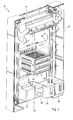
- la figure 3 est une vue en perspective du coffret de distribution de signaux que comporte l'installation illustrée sur la figure 1 ;
- la figure 4 est une autre vue en perspective de ce coffret, où le couvercle de fermeture a été enlevé ;
- la figue 5 est une vue en perspective éclatée de l'unité de distribution de signaux que comporte ce coffret ;
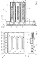
- la figure 6 est une vue en élévation, prise depuis l'avant, du concentrateur de câblage que comporte cette unité de distribution de signaux ;
- La figure 7 est une représentation schématique d'un cordon de brassage utilisé dans le coffret ;
- la figure 8 est une vue latérale en élévation-coupe de l'unité de distribution de signaux ;
- la figure 9 est un schéma de l'unité de distribution de signaux où tant le châssis du concentrateur de câblage que le boítier de chacune des trois unités électroniques actives n'a pas été représenté, ce schéma montrant d'une façon très générale le trajet des signaux de téléphonie et des signaux de réseau informatique local ; et
- la figure 10 est une vue similaire, mais montrant le trajet des signaux de télévision.
- dans la couche 65, pour le trajet matérialisé par la ligne 69, quatre pistes correspondant chacune à l'une des alvéoles de raccordement à vis du bornier 48 entre ce dernier et le connecteur 52 tandis qu'entre le connecteur 52 et chacune des prises 49A à 49H, il y a deux pistes correspondant à la paire de contacts 4 et 5 de cette prise;
- dans chacune des couches 66 et 67, pour les trajets matérialisés respectivement par la ligne 71 et par la ligne 70, deux pistes correspondant respectivement à la paire de contacts 1 et 2 et à la paire de contacts 3 et 6 de la prise 46 entre cette dernière et le connecteur 51 et de même entre le connecteur 51 et chacune des prises 49A à 49H.
Claims (18)
- Concentrateur de câblage, caractérisé en ce qu'il comporte :une première borne de connexion (43), adaptée à recevoir un câble (12) de distribution de signaux de télévision ;une deuxième borne de connexion (48), adaptée à recevoir un câble (13) de réseau téléphonique ;plusieurs troisièmes bornes de connexion (49A - 49H), chacune adaptée à recevoir un câble (49') de réseau informatique local ;un premier connecteur (50), adapté à recevoir une unité électronique active (16) de traitement de signaux de télévision ;un deuxième connecteur (52), adapté à recevoir une unité électronique active (18) de téléphonie ;un troisième connecteur (51), adapté à recevoir une unité électronique active (17) de réseau informatique local ;une carte de circuit imprimé (53) à laquelle est raccordée chaque dite première, deuxième et troisième borne de connexion (43, 48, 49A - 49H) et chaque dit premier, deuxième et troisième connecteur (50, 51, 52), ladite carte (53) reliant ladite première borne de connexion (43) audit premier connecteur (50), reliant ladite deuxième borne de connexion (48) audit deuxième connecteur (52), et reliant chaque dite troisième borne de connexion (49A - 49H) à chacun desdits premier connecteur (50), deuxième connecteur (52) et troisième connecteur (51) ; etun châssis (54) sur lequel est monté ladite carte de circuit imprimé (53), chaque dite première, deuxième et troisième borne de connexion (43, 48, 49A - 49H) ainsi que chaque dit premier, deuxième et troisième connecteur (50, 51, 52), lequel châssis présente un logement (56, 57, 58) pour chaque dite unité électronique active (16, 17, 18).
- Concentrateur selon la revendication 1, caractérisé en ce que lesdites troisièmes bornes de connexion (49A - 49H) sont disposées en groupe suivant une ligne tandis que chaque dit premier connecteur (50), deuxième connecteur (52) et troisième connecteur (51) est allongé, avec lesdites troisièmes bornes (49A - 49H), ledit premier connecteur (50), ledit deuxième connecteur (52) et ledit troisième connecteur (51) qui sont disposés en rangées successives.
- Concentrateur selon la revendication 2, caractérisé en ce que ledit premier connecteur (50) est le plus proche desdites troisièmes bornes de connexion (49A - 49H).
- Concentrateur selon la revendication 3, caractérisé en ce que ledit deuxième connecteur (52) est le plus éloigné desdites troisièmes bornes de connexion (49A - 49H) avec ledit troisième connecteur (51) qui est disposé entre le premier connecteur (50) et le deuxième connecteur (52).
- Concentrateur selon l'une quelconque des revendications 2 à 4, caractérisé en ce que ladite première borne de connexion (43) et ladite deuxième borne de connexion (48) sont disposées en groupe suivant une ligne, avec lesdites troisièmes bornes de connexion (49A - 49H), ledit premier connecteur (50), ledit deuxième connecteur (52), ledit troisième connecteur (51) et le groupe de ladite première borne (43) et de ladite deuxième borne (48) qui sont disposés en rangées successives.
- Concentrateur selon l'une quelconque des revendications 1 à 5, caractérisé en ce que :lesdites première borne de connexion (43) et deuxième borne de connexion (48) sont disposées à une première extrémité dudit concentrateur (42) ;lesdites troisièmes bornes de connexion (49A - 49H) sont disposées à une deuxième extrémité dudit concentrateur (42) ; etledit premier connecteur (50), ledit deuxième connecteur (52) et ledit troisième connecteur (51) sont disposés entre ladite première extrémité et ladite deuxième extrémité avec ledit premier connecteur (50) qui est le plus proche de ladite deuxième extrémité.
- Concentrateur selon la revendication 6, caractérisé en ce que ledit deuxième connecteur (52) est le plus proche de ladite première extrémité tandis que ledit troisième connecteur (51) est disposé entre ledit premier connecteur (50) et ledit deuxième connecteur (52).
- Concentrateur selon l'une quelconque des revendications 1 à 7, caractérisé en ce qu'il comporte une quatrième borne de connexion (44), adaptée à recevoir un deuxième câble (19) de distribution de signaux de télévision.
- Concentrateur selon la revendication 8, caractérisé en ce que ladite carte de circuit imprimé (53) comporte un répartiteur dont une entrée est reliée à ladite première borne de connexion (43), dont une première sortie, pour des signaux de télévision terrestre, est reliée audit premier connecteur (50) et dont une deuxième sortie, pour la totalité des signaux de télévision, est reliée à ladite quatrième borne de connexion (44).
- Concentrateur selon l'une quelconque des revendications 1 à 9, caractérisé en ce qu'il comporte une cinquième borne de connexion (45), adaptée à recevoir un troisième câble (20) de distribution de signaux de télévision.
- Concentrateur selon la revendication 10, caractérisé en ce que ladite carte de circuit imprimé (53) comporte un coupleur dont une première entrée est reliée à ladite première borne (43), dont une deuxième entrée est reliée à ladite cinquième borne (45) et dont une sortie est reliée audit connecteur (50).
- Concentrateur selon l'une quelconque des revendications 1 à 11, caractérisé en ce qu'il comporte une quatrième borne de connexion (44), adaptée à recevoir un deuxième câble (19) de distribution de signaux de télévision et une cinquième borne de connexion (45), adaptée à recevoir un troisième câble (20) de distribution de signaux de télévision tandis que ladite carte de circuit imprimé (53) comporte un répartiteur-coupleur dont une première entrée est reliée à ladite première borne de connexion (43), dont une deuxième entrée est reliée à ladite cinquième borne de connexion (45), dont une première sortie, pour des signaux de télévision terrestre, est reliée audit premier connecteur (50) et dont une deuxième sortie, pour la totalité des signaux de télévision, est reliée à ladite quatrième borne de connexion (44).
- Concentrateur selon l'une quelconque des revendications 1 à 12, caractérisé en ce qu'il comporte une sixième borne de connexion (46), adaptée à recevoir un câble (21) de réseau informatique local, avec ladite carte de circuit imprimé qui relie ladite sixième borne de connexion (46) à ladite deuxième borne (48) et audit troisième connecteur (51 ).
- Concentrateur selon l'une quelconque des revendications 1 à 13, caractérisé en ce qu'il comporte une septième borne de connexion (47), adaptée à recevoir un câble (21) de réseau téléphonique, avec ladite carte de circuit imprimé (53) qui relie ladite deuxième borne de connexion (48) à ladite septième borne de connexion (47).
- Concentrateur selon l'une quelconque des revendications 1 à 14, caractérisé en ce qu'il comporte au moins une borne de connexion (44-47) autre que ladite première borne de connexion (43), que ladite deuxième borne de connexion (48) et que ladite troisième borne de connexion (49A - 49H), avec ladite première borne de connexion (43), ladite deuxième borne de connexion (48) et chaque dite autre borne de connexion (44-47) qui sont disposées en groupe suivant une ligne.
- Concentrateur selon l'une quelconque des revendications 1 à 15, caractérisé en ce que ladite carte de circuit imprimé (53) présente plusieurs couches superposées (65-68) comportant chacune un substrat diélectrique et des pistes ou des pavés (76, 77) en matériau métallique conducteur disposés sur le substrat.
- Concentrateur selon la revendication 16, caractérisé en ce que ladite carte de circuit imprimé (53) présente une première dite couche (65) et une deuxième dite couche (68) pour relier ladite première borne de connexion (43) audit premier connecteur (50).
- Concentrateur selon la revendication 17, caractérisé en ce que ladite carte de circuit imprimé (53) comporte, pour chaque dite troisième borne (49A - 49H), un convertisseur (75) de signal asymétrique en un signal symétrique, avec chaque dit convertisseur (75) qui comporte une entrée reliée audit premier connecteur (50) tant par ladite première couche (65) que par ladite deuxième couche (68), et qui comporte une sortie reliée à ladite troisième borne de connexion (49A - 49H) par l'intermédiaire de la seule deuxième couche (68).
Applications Claiming Priority (2)
| Application Number | Priority Date | Filing Date | Title |
|---|---|---|---|
| FR0305045A FR2854302B1 (fr) | 2003-04-24 | 2003-04-24 | Concentrateur de cablage, unite de distribution des signaux le comportant et coffret comportant cette unite |
| FR0305045 | 2003-04-24 |
Publications (2)
| Publication Number | Publication Date |
|---|---|
| EP1471749A1 true EP1471749A1 (fr) | 2004-10-27 |
| EP1471749B1 EP1471749B1 (fr) | 2011-08-17 |
Family
ID=32947372
Family Applications (1)
| Application Number | Title | Priority Date | Filing Date |
|---|---|---|---|
| EP04291066A Expired - Lifetime EP1471749B1 (fr) | 2003-04-24 | 2004-04-23 | Concentrateur de câblage, unité de distribution des signaux le comportant et coffret comportant cette unité |
Country Status (4)
| Country | Link |
|---|---|
| US (1) | US7118422B2 (fr) |
| EP (1) | EP1471749B1 (fr) |
| KR (1) | KR101108938B1 (fr) |
| FR (1) | FR2854302B1 (fr) |
Cited By (2)
| Publication number | Priority date | Publication date | Assignee | Title |
|---|---|---|---|---|
| WO2006034443A1 (fr) * | 2004-09-20 | 2006-03-30 | American Power Conversion Corporation | Armoire de distribution de donnees et de courant |
| FR2954037A1 (fr) * | 2009-12-14 | 2011-06-17 | Legrand France | Systeme pour distribuer au moins des signaux de reseau informatique local et des signaux d'une autre nature |
Families Citing this family (2)
| Publication number | Priority date | Publication date | Assignee | Title |
|---|---|---|---|---|
| JP4152269B2 (ja) * | 2003-07-04 | 2008-09-17 | 矢崎総業株式会社 | 部品半装着防止用接続ブロックとそれを備えた電気接続箱 |
| KR101599146B1 (ko) * | 2014-08-14 | 2016-03-02 | 한국항공우주연구원 | 점퍼 부착시스템 |
Citations (7)
| Publication number | Priority date | Publication date | Assignee | Title |
|---|---|---|---|---|
| EP0724365A2 (fr) * | 1995-01-27 | 1996-07-31 | The Whitaker Corporation | Système de câblage de communications comprenant un montage de sortie reconfigurable |
| GB2317996A (en) * | 1996-09-05 | 1998-04-08 | Soho Networks Limited | Building communication system |
| WO1998056223A1 (fr) * | 1997-06-04 | 1998-12-10 | T.R.T. Lucent Technologies | Cadre de support d'unites enfichables electroniques |
| US6028769A (en) * | 1996-05-20 | 2000-02-22 | Adc Telecommunication, Inc. | Multiple integrated service unit for communication system |
| EP1069784A2 (fr) * | 1999-07-15 | 2001-01-17 | NK Networks GmbH | Connecteur distributeur variable |
| EP1079491A2 (fr) * | 1999-08-18 | 2001-02-28 | Reichle & De-Massari AG | Boítier pour un poste de distribution |
| WO2003003758A2 (fr) * | 2001-06-29 | 2003-01-09 | Adc Telecommunications, Inc. | Ensemble separateur de ligne telephonique ordinaire (pots) a haute densite de circuits |
Family Cites Families (14)
| Publication number | Priority date | Publication date | Assignee | Title |
|---|---|---|---|---|
| US5893763A (en) * | 1996-09-30 | 1999-04-13 | Hubbell Incorporated | Transition adapter for conductor cables |
| US6261107B1 (en) * | 1998-01-16 | 2001-07-17 | Molex Incorporated | Surface mount connector having improved terminal structure |
| JP2001015223A (ja) * | 1999-06-25 | 2001-01-19 | Nec Corp | 汎用コネクタおよびその結合方法 |
| US20030119490A1 (en) * | 2001-02-26 | 2003-06-26 | Jahangir Mohammed | Wireless communications handset for facilitating licensed and unlicensed wireless communications, and method of operation |
| JP2002330526A (ja) * | 2001-04-27 | 2002-11-15 | Yazaki Corp | 電気接続箱 |
| FR2830156B1 (fr) | 2001-09-25 | 2004-11-26 | Henri Lee | Systeme de distribution tv et unite de traitement utilisee dans ce systeme de distribution |
| US6786755B2 (en) * | 2002-03-27 | 2004-09-07 | Molex Incorporated | Differential signal connector assembly with improved retention capabilities |
| EP2334127A3 (fr) * | 2002-10-18 | 2012-07-11 | Kineto Wireless, Inc. | Procédé et dispositifs pour l'enregistrement et la radiorecherche d'un dispositif de télécommunication |
| US20040203789A1 (en) * | 2002-11-12 | 2004-10-14 | Hammond Marc John | Location service assisted transition between wireless networks |
| US7627338B2 (en) * | 2003-06-06 | 2009-12-01 | At&T Intellectual Property I, L.P. | System and method for providing integrated voice and data services utilizing wired cordless access with unlicensed spectrum and wired access with licensed spectrum |
| JP4256757B2 (ja) * | 2003-10-07 | 2009-04-22 | 富士通株式会社 | 筐体及び電子装置 |
| US20050113069A1 (en) * | 2003-11-25 | 2005-05-26 | Intel Corporation | User authentication through separate communication links |
| US6875031B1 (en) * | 2003-12-05 | 2005-04-05 | Hon Hai Precision Ind. Co., Ltd. | Electrical connector with circuit board module |
| US7136641B2 (en) * | 2004-03-18 | 2006-11-14 | Motorola Inc. | Alternative network selection for a communication device |
-
2003
- 2003-04-24 FR FR0305045A patent/FR2854302B1/fr not_active Expired - Fee Related
-
2004
- 2004-04-23 EP EP04291066A patent/EP1471749B1/fr not_active Expired - Lifetime
- 2004-04-23 KR KR1020040028196A patent/KR101108938B1/ko not_active Expired - Fee Related
- 2004-04-26 US US10/831,152 patent/US7118422B2/en not_active Expired - Fee Related
Patent Citations (7)
| Publication number | Priority date | Publication date | Assignee | Title |
|---|---|---|---|---|
| EP0724365A2 (fr) * | 1995-01-27 | 1996-07-31 | The Whitaker Corporation | Système de câblage de communications comprenant un montage de sortie reconfigurable |
| US6028769A (en) * | 1996-05-20 | 2000-02-22 | Adc Telecommunication, Inc. | Multiple integrated service unit for communication system |
| GB2317996A (en) * | 1996-09-05 | 1998-04-08 | Soho Networks Limited | Building communication system |
| WO1998056223A1 (fr) * | 1997-06-04 | 1998-12-10 | T.R.T. Lucent Technologies | Cadre de support d'unites enfichables electroniques |
| EP1069784A2 (fr) * | 1999-07-15 | 2001-01-17 | NK Networks GmbH | Connecteur distributeur variable |
| EP1079491A2 (fr) * | 1999-08-18 | 2001-02-28 | Reichle & De-Massari AG | Boítier pour un poste de distribution |
| WO2003003758A2 (fr) * | 2001-06-29 | 2003-01-09 | Adc Telecommunications, Inc. | Ensemble separateur de ligne telephonique ordinaire (pots) a haute densite de circuits |
Cited By (3)
| Publication number | Priority date | Publication date | Assignee | Title |
|---|---|---|---|---|
| WO2006034443A1 (fr) * | 2004-09-20 | 2006-03-30 | American Power Conversion Corporation | Armoire de distribution de donnees et de courant |
| FR2954037A1 (fr) * | 2009-12-14 | 2011-06-17 | Legrand France | Systeme pour distribuer au moins des signaux de reseau informatique local et des signaux d'une autre nature |
| WO2011080412A1 (fr) * | 2009-12-14 | 2011-07-07 | Legrand France | Système pour distribuer au moins des signaux de réseau informatique local et des signaux d'une autre nature |
Also Published As
| Publication number | Publication date |
|---|---|
| US20050032418A1 (en) | 2005-02-10 |
| KR101108938B1 (ko) | 2012-01-31 |
| FR2854302B1 (fr) | 2005-07-22 |
| US7118422B2 (en) | 2006-10-10 |
| EP1471749B1 (fr) | 2011-08-17 |
| FR2854302A1 (fr) | 2004-10-29 |
| KR20040093013A (ko) | 2004-11-04 |
Similar Documents
| Publication | Publication Date | Title |
|---|---|---|
| CA2251995C (fr) | Dispositif d'interface entre equipements d'une installation | |
| EP1114574A1 (fr) | Dispositif de connexion pour un ensemble de structures modulaires porte-cartes electroniques et rack equipe d'un tel dispositif, accueillant un tel ensemble | |
| EP3179582B1 (fr) | Tableau électrique comportant une interface de communication | |
| FR3073679A1 (fr) | Appareillage electrique | |
| FR2666695A1 (fr) | Connecteur pour cable de type paire blindee a drain de masse. | |
| EP1436991B1 (fr) | Syteme de distribution tv et unite de traitement utilisee dans ce systeme de distribution | |
| FR2969404A1 (fr) | Dispositif de communication et tableau electrique comportant un tel dispositif | |
| EP1471749B1 (fr) | Concentrateur de câblage, unité de distribution des signaux le comportant et coffret comportant cette unité | |
| FR3135171A1 (fr) | Boîtiers de connexion pour câbles Ethernet à paire unique et réseaux Ethernet câblés associés | |
| BE898523A (fr) | Ensemble de panneaux d'information. | |
| EP0123595B1 (fr) | Dispositif entrée/sortie pour appareil du genre automate programmable, gamme de tels dispositifs et procédé pour réaliser leur bornier | |
| EP1285448A1 (fr) | Poste de transformation volutif pour r seaux en coupure d'art re | |
| EP0889565A1 (fr) | Enveloppe pour appareillages électriques | |
| EP1958298B1 (fr) | Dispositif d'interruption d'une ligne de communication de donnees | |
| FR2800927A1 (fr) | Repartiteur de puissance electrique pour tiroir enfichable et tiroir enfichable | |
| CA2475381C (fr) | Module de raccordement pour chaine de securite | |
| US6570965B1 (en) | Configurable telephone line distribution modules for designating primary and secondary telephone lines | |
| EP1617664B1 (fr) | Système de distribution de signaux de télévision et de signaux de réseau informatique local | |
| FR2866157A1 (fr) | Interface passive de reseau, boitier individuel comprenant une telle interface passive et dispositif electronique comprenant une telle interface passive | |
| CH547022A (fr) | Dispositif pour relier electriquement entre eux plusieus groupes de conducteurs d'une installation electrique. | |
| EP1300911B1 (fr) | Dispositif de connexion destiné à se connecter à un bloc réglette | |
| EP1467522B1 (fr) | Module distributeur configurable de services de communications pour des habitations et assimilés | |
| EP4738628A1 (fr) | Tableau electrique pour un aeronef | |
| WO2025103908A1 (fr) | Dispositif de mesure de la puissance active dans des circuits électriques | |
| EP1183877A1 (fr) | Panneaux de communication a blindage electrique disposes de maniere dense |
Legal Events
| Date | Code | Title | Description |
|---|---|---|---|
| PUAI | Public reference made under article 153(3) epc to a published international application that has entered the european phase |
Free format text: ORIGINAL CODE: 0009012 |
|
| AK | Designated contracting states |
Kind code of ref document: A1 Designated state(s): AT BE BG CH CY CZ DE DK EE ES FI FR GB GR HU IE IT LI LU MC NL PL PT RO SE SI SK TR |
|
| AX | Request for extension of the european patent |
Extension state: AL HR LT LV MK |
|
| 17P | Request for examination filed |
Effective date: 20041224 |
|
| AKX | Designation fees paid |
Designated state(s): BE DE FR IT |
|
| RAP1 | Party data changed (applicant data changed or rights of an application transferred) |
Owner name: LEGRAND FRANCE |
|
| GRAP | Despatch of communication of intention to grant a patent |
Free format text: ORIGINAL CODE: EPIDOSNIGR1 |
|
| GRAS | Grant fee paid |
Free format text: ORIGINAL CODE: EPIDOSNIGR3 |
|
| GRAA | (expected) grant |
Free format text: ORIGINAL CODE: 0009210 |
|
| AK | Designated contracting states |
Kind code of ref document: B1 Designated state(s): BE DE FR IT |
|
| REG | Reference to a national code |
Ref country code: DE Ref legal event code: R096 Ref document number: 602004033966 Country of ref document: DE Effective date: 20111027 |
|
| PLBE | No opposition filed within time limit |
Free format text: ORIGINAL CODE: 0009261 |
|
| STAA | Information on the status of an ep patent application or granted ep patent |
Free format text: STATUS: NO OPPOSITION FILED WITHIN TIME LIMIT |
|
| 26N | No opposition filed |
Effective date: 20120521 |
|
| REG | Reference to a national code |
Ref country code: DE Ref legal event code: R097 Ref document number: 602004033966 Country of ref document: DE Effective date: 20120521 |
|
| BERE | Be: lapsed |
Owner name: LEGRAND FRANCE Effective date: 20120430 |
|
| PG25 | Lapsed in a contracting state [announced via postgrant information from national office to epo] |
Ref country code: BE Free format text: LAPSE BECAUSE OF NON-PAYMENT OF DUE FEES Effective date: 20120430 |
|
| REG | Reference to a national code |
Ref country code: DE Ref legal event code: R119 Ref document number: 602004033966 Country of ref document: DE Effective date: 20121101 |
|
| PGFP | Annual fee paid to national office [announced via postgrant information from national office to epo] |
Ref country code: IT Payment date: 20130423 Year of fee payment: 10 |
|
| PG25 | Lapsed in a contracting state [announced via postgrant information from national office to epo] |
Ref country code: DE Free format text: LAPSE BECAUSE OF FAILURE TO SUBMIT A TRANSLATION OF THE DESCRIPTION OR TO PAY THE FEE WITHIN THE PRESCRIBED TIME-LIMIT Effective date: 20121101 |
|
| PG25 | Lapsed in a contracting state [announced via postgrant information from national office to epo] |
Ref country code: IT Free format text: LAPSE BECAUSE OF NON-PAYMENT OF DUE FEES Effective date: 20140423 |
|
| REG | Reference to a national code |
Ref country code: FR Ref legal event code: PLFP Year of fee payment: 12 |
|
| PGFP | Annual fee paid to national office [announced via postgrant information from national office to epo] |
Ref country code: FR Payment date: 20150429 Year of fee payment: 12 |
|
| REG | Reference to a national code |
Ref country code: FR Ref legal event code: ST Effective date: 20161230 |
|
| PG25 | Lapsed in a contracting state [announced via postgrant information from national office to epo] |
Ref country code: FR Free format text: LAPSE BECAUSE OF NON-PAYMENT OF DUE FEES Effective date: 20160502 |