EP1471640A2 - PWM Signalerzeuger und PWM Signalerzeugungsverfahren - Google Patents
PWM Signalerzeuger und PWM Signalerzeugungsverfahren Download PDFInfo
- Publication number
- EP1471640A2 EP1471640A2 EP04009358A EP04009358A EP1471640A2 EP 1471640 A2 EP1471640 A2 EP 1471640A2 EP 04009358 A EP04009358 A EP 04009358A EP 04009358 A EP04009358 A EP 04009358A EP 1471640 A2 EP1471640 A2 EP 1471640A2
- Authority
- EP
- European Patent Office
- Prior art keywords
- pulse
- pulse width
- signal
- pwm
- digital signal
- Prior art date
- Legal status (The legal status is an assumption and is not a legal conclusion. Google has not performed a legal analysis and makes no representation as to the accuracy of the status listed.)
- Withdrawn
Links
- 238000000034 method Methods 0.000 title claims abstract description 20
- 238000013139 quantization Methods 0.000 claims description 11
- 230000003247 decreasing effect Effects 0.000 claims description 7
- 238000010586 diagram Methods 0.000 description 17
- 238000001228 spectrum Methods 0.000 description 14
- 230000000295 complement effect Effects 0.000 description 2
- 238000005070 sampling Methods 0.000 description 2
- 238000010420 art technique Methods 0.000 description 1
- 238000007493 shaping process Methods 0.000 description 1
Images


Classifications
-
- H—ELECTRICITY
- H03—ELECTRONIC CIRCUITRY
- H03F—AMPLIFIERS
- H03F3/00—Amplifiers with only discharge tubes or only semiconductor devices as amplifying elements
- H03F3/20—Power amplifiers, e.g. Class B amplifiers, Class C amplifiers
- H03F3/21—Power amplifiers, e.g. Class B amplifiers, Class C amplifiers with semiconductor devices only
- H03F3/217—Class D power amplifiers; Switching amplifiers
- H03F3/2173—Class D power amplifiers; Switching amplifiers of the bridge type
-
- H—ELECTRICITY
- H02—GENERATION; CONVERSION OR DISTRIBUTION OF ELECTRIC POWER
- H02M—APPARATUS FOR CONVERSION BETWEEN AC AND AC, BETWEEN AC AND DC, OR BETWEEN DC AND DC, AND FOR USE WITH MAINS OR SIMILAR POWER SUPPLY SYSTEMS; CONVERSION OF DC OR AC INPUT POWER INTO SURGE OUTPUT POWER; CONTROL OR REGULATION THEREOF
- H02M1/00—Details of apparatus for conversion
- H02M1/08—Circuits specially adapted for the generation of control voltages for semiconductor devices incorporated in static converters
- H02M1/088—Circuits specially adapted for the generation of control voltages for semiconductor devices incorporated in static converters for the simultaneous control of series or parallel connected semiconductor devices
-
- H—ELECTRICITY
- H02—GENERATION; CONVERSION OR DISTRIBUTION OF ELECTRIC POWER
- H02M—APPARATUS FOR CONVERSION BETWEEN AC AND AC, BETWEEN AC AND DC, OR BETWEEN DC AND DC, AND FOR USE WITH MAINS OR SIMILAR POWER SUPPLY SYSTEMS; CONVERSION OF DC OR AC INPUT POWER INTO SURGE OUTPUT POWER; CONTROL OR REGULATION THEREOF
- H02M7/00—Conversion of ac power input into dc power output; Conversion of dc power input into ac power output
- H02M7/42—Conversion of dc power input into ac power output without possibility of reversal
- H02M7/44—Conversion of dc power input into ac power output without possibility of reversal by static converters
- H02M7/48—Conversion of dc power input into ac power output without possibility of reversal by static converters using discharge tubes with control electrode or semiconductor devices with control electrode
- H02M7/53—Conversion of dc power input into ac power output without possibility of reversal by static converters using discharge tubes with control electrode or semiconductor devices with control electrode using devices of a triode or transistor type requiring continuous application of a control signal
- H02M7/537—Conversion of dc power input into ac power output without possibility of reversal by static converters using discharge tubes with control electrode or semiconductor devices with control electrode using devices of a triode or transistor type requiring continuous application of a control signal using semiconductor devices only, e.g. single switched pulse inverters
- H02M7/5387—Conversion of dc power input into ac power output without possibility of reversal by static converters using discharge tubes with control electrode or semiconductor devices with control electrode using devices of a triode or transistor type requiring continuous application of a control signal using semiconductor devices only, e.g. single switched pulse inverters in a bridge configuration
-
- H—ELECTRICITY
- H03—ELECTRONIC CIRCUITRY
- H03K—PULSE TECHNIQUE
- H03K7/00—Modulating pulses with a continuously-variable modulating signal
- H03K7/08—Duration or width modulation ; Duty cycle modulation
-
- H—ELECTRICITY
- H03—ELECTRONIC CIRCUITRY
- H03M—CODING; DECODING; CODE CONVERSION IN GENERAL
- H03M1/00—Analogue/digital conversion; Digital/analogue conversion
- H03M1/66—Digital/analogue converters
- H03M1/82—Digital/analogue converters with intermediate conversion to time interval
- H03M1/822—Digital/analogue converters with intermediate conversion to time interval using pulse width modulation
-
- H—ELECTRICITY
- H02—GENERATION; CONVERSION OR DISTRIBUTION OF ELECTRIC POWER
- H02M—APPARATUS FOR CONVERSION BETWEEN AC AND AC, BETWEEN AC AND DC, OR BETWEEN DC AND DC, AND FOR USE WITH MAINS OR SIMILAR POWER SUPPLY SYSTEMS; CONVERSION OF DC OR AC INPUT POWER INTO SURGE OUTPUT POWER; CONTROL OR REGULATION THEREOF
- H02M1/00—Details of apparatus for conversion
- H02M1/0003—Details of control, feedback or regulation circuits
- H02M1/0012—Control circuits using digital or numerical techniques
-
- H—ELECTRICITY
- H03—ELECTRONIC CIRCUITRY
- H03M—CODING; DECODING; CODE CONVERSION IN GENERAL
- H03M1/00—Analogue/digital conversion; Digital/analogue conversion
- H03M1/66—Digital/analogue converters
- H03M1/82—Digital/analogue converters with intermediate conversion to time interval
Definitions
- the present invention relates to a PWM signal generator and a PWM signal generating method for generating a pulse width modulation (PWM) signal in accordance with a pulse code modulation (PCM) digital signal.
- PWM pulse width modulation
- PCM pulse code modulation
- Fig. 1 shows the configuration of a digital-to-analog converter to which a conventional PWM signal generator is applied.
- the digital-to-analog converter comprises a digital interface 1, an oversampling circuit 2, a delta-sigma modulator 3, a PCM-PWM converter 4, a differential amplifier 5, and a low pass filter 6.
- Fig. 2 shows the configuration of a conventional digital amplifier to which a conventional PWM signal generator is applied.
- the digital amplifier comprises a digital interface 11, an oversampling circuit 12, a digital volume 13, a delta-signal modulator 14, a PCM-PWM converter 15, a power switching circuit 16, and a low pass filter 17.
- the digital amplifier 2 in Fig. 2 differs from the digital-to-analog converter illustrated in Fig. 1 only in that the digital volume 13 is provided, and the differential amplifier 5 is replaced by the power switching circuit 16, and is identical in the rest, so that the digital amplifier in Fig. 2 will be next described.
- a digital signal read from a disk such as CD, DVD or the like is supplied into the digital amplifier through the digital interface 11, and the sampling frequency of the digital signal is increased by the oversampling circuit 12. Subsequently, the gain of the digital signal is adjusted by the digital volume 13.
- the delta-sigma modulator 14 is for example, a noise shaper having subtractors 21, 23, a quantizer 22, and a filter 24, as shown in Fig. 3, and reduces the number of quantization bits of the gain adjusted digital signal.
- quantization noise Nq(z) output from the subtractor 23 is fed back to the subtractor 21 on the input side through the filter 24 (transfer function H(z)).
- the transfer function H(z) of the filter 24 the quantization noise can be shifted to a higher frequency band to ensure the S/N ratio for an audio band, as shown in Fig. 4A.
- Fig. 4B is an enlarged view of the frequency spectrum in Fig. 4A.
- the output digital signal of the delta-sigma modulator 14 is converted to two types of PWM signals by the PCM-PWM converter 15.
- the PWM signals consist of PWM_A and PWM_B which are supplied to the power switching circuit 16.
- the power switching circuit 16 converts the PWM signals PWM_A and PWM_B to a PWM differential signal indicating a differential component of PWM_A-PWM_B.
- the power switching circuit 16 includes an H-bridge switching circuit having four switching elements SW1 - SW4, for example, as shown in Fig. 5.
- the differential signal PWM_A-PWM_B is supplied to a speaker 18 through the low pass filter 17.
- the low pass filter 17 supplies the speaker 18 with an audio band signal which is a lower band component of the differential signal PWM_A-PWM_B.
- Fig. 6 shows a method of generating a single sided binary PWM signal.
- a PWM signal PWM_A having a pulse width in accordance with a PCM signal, and PWM_B which is a NOT signal of PWM_A are generated.
- a difference PWM_A-PWM_B of the PWM signals PWM_A and PWM_B is a PWM differential signal.
- the frequency spectrum of the PWM differential signal is as shown in Fig. 7, where a harmonic distortion is generated and the noise floor rises, as compared with the output of the delta-sigma modulator shown in Fig. 4.
- Single-sided three-valued PWM, or double sided three-valued PWM is known as a prior art technique for reducing the harmonic distortion and lowering the noise floor.
- a method of generating a single sided three-valued PWM signal is performed as shown in Fig. 8.
- PWM signals PWM_A which has a pulse width in accordance with a PCM signal
- PWM_B which is 2's complement signal of PWM_A are generated.
- the difference PWM_A-PWM_B between the PWM signals PWM_A and PWM_B is a PWM differential signal.
- the frequency spectrum of the PWM differential signal is as shown in Fig. 9, where even-number order harmonic distortions disappear and the noise floor is lowered.
- a method of generating a double sided three-valued PWM signal is performed as shown in Fig. 10.
- PWM signals PWM_A which has a pulse width in accordance with a PCM signal
- PWM_B which is a 2's complement signal of PWM_A are generated to be symmetric with respect to the center (four in this case).
- the difference PWM_A-PWM_B between the PWM signals PWM_A and PWM_B is a final PWM output signal.
- the frequency spectrum of the PWM output signal is as shown in Fig. 11, where even-number order harmonic distortions disappear and the noise floor is lowered further as compared with the single sided three-valued PWM.
- a PWM signal generator comprises signal generating means for generating one or two pulses which have a pulse width or a total pulse width corresponding to a value represented by a pulse code modulation digital signal and which have a symmetric positional relationship with respect to the position of one half of a predetermined length, as a first pulse width modulation signal
- the signal generating means includes a PCM (pulse code modulation)-PWM converter for generating a first pulse and a second pulse in accordance with the value represented by the digital signal, and a difference detector for outputting the difference between the first pulse and the second pulse, as the first pulse width modulation signal, and when the value represented by the digital signal is zero, the first pulse and the second pulse are equal to each other in pulse width, and when the value represented by the digital signal changes by one, one of the first and second pulses does not change in pulse width and the other of the first and second pulses changes in pulse width by two slots.
- PCM pulse code modulation
- a PWM signal generating method generates one or two pulses having a pulse width or a total pulse width corresponding to a value represented by a pulse code modulation digital signal and placed in a symmetric positional relationship with respect to the position of one half of a predetermined length, as a first pulse width modulation signal, the method comprising the steps of: generating a first pulse and a second pulse in accordance with a value represented by the digital signal; outputting the difference between the first pulse and the second pulse, as the first pulse width modulation signal; and controlling the first pulse and the second pulse so that when the value represented by the digital signal is zero, the first pulse and the second pulse are equal to each other in pulse width, and when the value represented by the digital signal changes by one, one of the first and second pulses does not change in pulse width and the other of the first and second pulses changes in pulse width by two slots.
- a PWM signal generating method generates one or two pulses having a pulse width or a total pulse width corresponding to a value represented by a pulse code modulation digital signal and placed in a symmetric positional relationship with respect to the position of one half of a predetermined length, as a first pulse width modulation signal, the method comprising the steps of: controlling the first pulse and the second pulse so that when the value represented by the digital signal is zero, the first pulse and the second pulse are equal to each other in pulse width, and when the value represented by the digital signal changes by one, one of the first and second pulses does not change in pulse width and the other of the first and second pulses changes in pulse width by two slots; detecting that a value represented by the digital signal is an odd-number; and when the value represented by the digital signal is an odd-number, generating the first pulse width modulation signal and a second pulse width modulation signal, alternately, the second pulse width modulation signal indicating two pulses having a total pulse width corresponding to the odd value and placed in
- a digital-to-analog converter comprises: an oversampling circuit for oversampling an input pulse code modulation digital signal; a delta-sigma modulator for decreasing the number of quantization bits of an output digital signal of the oversampling circuit; a PWM signal generator for generating one or two pulses having a pulse width or a total pulse width corresponding to a value represented by an output digital signal of the delta-sigma modulator and placed in a symmetric positional relationship with respect to the position of one half of a predetermined length, as a first pulse width modulation signal; and a low pass filter for outputting a low band component of the first pulse width modulation signal, wherein the PWM signal generator includes a PCM-PWM converter for generating a first pulse and a second pulse in accordance with the value represented by the output digital signal of the delta-sigma modulator, and a difference detector for outputting the difference between the first pulse and the second pulse, as the first pulse width modulation signal; and when the value represented by the output digital signal
- a digital amplifier comprises: an oversampling circuit for oversampling a pulse code modulation input digital signal; a digital volume for changing a gain indicated by an output digital signal of the oversampling circuit; a delta-sigma modulator for decreasing the number of quantization bits of an output digital signal of the digital volume; a PWM signal generator for generating one or two pulses having a pulse width or a total pulse width corresponding to a value represented by an output digital signal of the delta-sigma modulator and placed in a symmetric positional relationship with respect to the position of one half of a predetermined length, as a first pulse width modulation signal; and a low pass filter for outputting a low band component of the first pulse width modulation signal, wherein the PWM signal generator includes a PCM-PWM converter for generating a first pulse and a second pulse in accordance with the value represented by the output digital signal of the delta-sigma modulator, and a difference detector for outputting the difference between the first pulse and the second pulse, as the first pulse
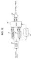
- Fig. 12 illustrates the general configuration of a PWM signal generator according to the present invention.
- the PWM signal generator comprises an offset circuit 30, PCM-PWM converters 31, 32, a switch 33, a difference detector 34, and a controller 35.
- the offset circuit 30 adds an offset portion to a PCM input digital signal. Assuming that the input digital signal has the number of quantization bits B, the number of slots SLOT is 2 B , and a digital signal PCM takes a value in the range of -2 B1 +1 to 2 B1 -1.
- the offset portion by the offset circuit 30 is SLOT/2, so that a digital signal PCMOFST output from the offset circuit 30 can be represented by PCM+SLOT/2.
- the PCM-PWM converters 31, 32 generate a PWM signal PWM_A (first pulse) and a PWM signal PWM_B (second pulse) for the PCM digital signal PCMOFST.
- the PWM signals PWM_A and PWM_B generated by the PCM-PWM converter 31 are labeled "X-series," while the PWM signals PWM_A and PWM_B generated by the PCM-PWM converter 32 are labeled "Y-series.”
- a slot value at the leading edge of each pulse of the PWM signals PWM_A and PWM_B is LE, and a slot value at the trailing edge of the same is TE, as shown in Fig. 13.
- the switch 33 supplies the difference detector 34 with the PWM signals PWM_A and PWM_B from one of the PCM-PWM converters 31, 32.
- the switch 33 is controlled by the controller 35.
- the difference detector 34 outputs the difference PWM_A-PWM_B between the supplied PWM signals PWM_A and PWM_B as a final PWM signal.
- the controller 35 acts as odd-number detecting means to determine whether or not the digital signal PCMOFST is an odd-number or an even-number.
- the controller 35 also controls a selecting position of the switch 33 in accordance with the determination result. Specifically, when the least significant bit (LSB) of the digital signal PCMOFST is 0, the digital signal PCMOFST is determined to represent an even-number, whereas when the least significant bit is 1, the digital signal PCMOFST is determined to represent an odd-number.
- the switch 33 is instructed to select the output of the X-series PCM-PWM converter 31.
- the switch 33 is instructed to select the output of the Y-series PCM-PWM converter 32.
- the number of slots SLOT is set to 2 B , and a flag FLAG is set to 0 (step S1).
- a PCM input digital signal is read in synchronism with a sampling timing (step S2), and the digital signal PCMOFST is set to PCM+SLOT/2 in the offset circuit 30 (step S3).
- the controller 35 determines whether or not the least significant bit (LSB) of the digital signal PCMOFST is 1 (step S4). If the least significant bit is 0, i.e., if the digital signal PCMOFST represents an even-number, an X-series selection instruction is generated from the controller 35 to the switch 33 (step S5).
- the output signals PWM_A and PWM_B of the X-series PCM-PWM converter 31 are supplied to the difference detector 34 through the switch 33, and a final PWM signal PWM_A-PWM_B (first pulse width modulation signal) is output from the difference detector 34 in accordance with the output signals PWM_A and PWM_B of the X-series PCM-PWM converter 31.
- the output signals PWM_A and PWM_B of the Y-series PCM-PWM converter 32 are supplied to the difference detector 34 through the switch 33, and a final PWM signal PWM_A-PWM_B (second pulse width modulation signal) is output from the difference detector 34 in accordance with the output signals PWM_A and PWM_B of the Y-series PCM-PWM converter 32.
- step S5 After the execution of step S5, S8, or S10, the flow returns to step S2 to repeat the foregoing operation.
- the flag FLAG alternately repeats 0 and 1, so that the difference detector 34 alternately outputs the PWM signal PWM_A-PWM_B (first pulse width modulation signal) associated with the X-series and the PWM signal PWM_A-PWM_B (second pulse width modulation signal) associated with the Y-series.
- Figs. 15 and 16 show the waveforms of the PWM signals PWM_A, PWM_B, and PWM_A-PWM_B associated with the X-series and the PWM signals PWM_A, PWM_B, and PWM_A-PWM_B associated with the Y-series for a 3-bit digital signal value (4 to -4). While the digital signal can take a value in the range of 3 to -3, 4 and -4 are also shown for facilitating the understanding of the description. Odd-numbers (1, 3, -3, -1) alone are shown for the PWM signals PWM_A, PWM_B, and PWM_A-PWM_B associated with the Y-series.
- the PWM signal PWM_B is increased by two slots such that it is symmetric with respect to four to have a width of two slots. Subsequently, the operations (X1) and (X2) are alternately performed each time the PCM digital signal value is decreased by one.
- the signal waveform of the X-series PWM_A-PWM_B is symmetric to even-number PCM signal values with respect to the positions of 1/4 and 3/4 of the maximum number of slots, it is not symmetric to odd-number PCM signal values. Therefore, the Y-series is generated for the odd-number PCM signal values by inverting the signal waveform of the X-series PWM_A-PWM_B with respect to the positions of 1/4 and 3/4 of the maximum number of slots.
- the frequency spectrum of the PWM signal PWM_A-PWM_B associated with the X-series alone is, for example, as shown in Fig. 17. It can be seen from the spectrum of Fig. 17 that the harmonic distortion is equivalent to that of the double-sided three-valued PWM, whereas the noise floor is higher than that of the single-sided three-valued PWM.
- the frequency spectrum of the PWM output signal comprised of the PWM signal PWM_A-PWM_B associated with the X-series and the PWM signal PWM_A-PWM_B associated with the Y-series alternately output from the difference detector 34 is, for example, as shown in Fig. 18.
- the harmonic distortion is equivalent to that of the double-sided three-valued PWM, and the noise floor is equivalent to that of the single-sided three-value PWM.
- the PWM signals PWM_A and PWM_B are increased or decreased in units of two slots, it is possible to generate a PWM signal symmetric with respect to the center of a maximum slot width without doubling the clock frequency.
- the harmonic distortion can be reduced to a level equivalent to that of the double-sided three-valued PWM.
- the PWM signal PWM_A-PWM_B associated with the X-series and the PWM signal PWM_A-PWM_B associated with the Y-series are alternately output.
- the output PWM_A-PWM_B is quasi symmetric with respect to the positions of 1/4 and 3/4 of the maximum number of slots, so that the noise floor can be reduced to a level equivalent to that of the single-sided three-valued PWM.
- the PWM signal generator comprises the offset circuit 30, PCM-PWM converters 31, 32, switch 33, difference detector 34, and controller 35, this is not a limitation.
- the X-series and Y-series PWM signals may be generated by a single PCM-PWM converter and the controller as shown in the flow chart of Fig. 14 to omit the switch.
- the PWM signal generator according to the present invention can be applied to the digital-to-analog converter shown in Fig. 1 and the digital amplifier shown in Fig. 2.
- the generation of the pulse width modulation signal involves generating one or two pulses having a pulse width or a total pulse width corresponding to a value represented by a pulse code modulation digital signal and placed in a symmetric positional relationship with respect to the position of the half of a predetermined length, as a first pulse width modulation signal, and when the digital signal represents an odd value, alternately generating the first pulse width modulation signal and a second pulse width modulation signal comprising two pulses having a total pulse width corresponding to the odd value and placed in a symmetric positional relationship with one pulse or two pulses of the first pulse width modulation signal with respect to the positions of 1/4 and 3/4 of a predetermined length, thereby making it possible to reduce both the harmonic distortion and noise floor without changing the clock frequency.
Landscapes
- Engineering & Computer Science (AREA)
- Power Engineering (AREA)
- Theoretical Computer Science (AREA)
- Compression, Expansion, Code Conversion, And Decoders (AREA)
- Amplifiers (AREA)
- Analogue/Digital Conversion (AREA)
Applications Claiming Priority (2)
| Application Number | Priority Date | Filing Date | Title |
|---|---|---|---|
| JP2003121163 | 2003-04-25 | ||
| JP2003121163A JP2004328428A (ja) | 2003-04-25 | 2003-04-25 | Pwm信号発生器及びpwm信号発生方法並びにディジタル・アナログ変換器及びディジタルアンプ |
Publications (2)
| Publication Number | Publication Date |
|---|---|
| EP1471640A2 true EP1471640A2 (de) | 2004-10-27 |
| EP1471640A3 EP1471640A3 (de) | 2005-01-26 |
Family
ID=32959684
Family Applications (1)
| Application Number | Title | Priority Date | Filing Date |
|---|---|---|---|
| EP04009358A Withdrawn EP1471640A3 (de) | 2003-04-25 | 2004-04-20 | PWM Signalerzeuger und PWM Signalerzeugungsverfahren |
Country Status (3)
| Country | Link |
|---|---|
| US (1) | US6992610B2 (de) |
| EP (1) | EP1471640A3 (de) |
| JP (1) | JP2004328428A (de) |
Cited By (2)
| Publication number | Priority date | Publication date | Assignee | Title |
|---|---|---|---|---|
| GB2425668A (en) * | 2005-01-17 | 2006-11-01 | Wolfson Microelectronics Plc | A class D amplifier with a guard band quantizer to prevent output of narrow pulses |
| WO2007090164A2 (en) | 2006-01-31 | 2007-08-09 | D2Audio Corporation | Systems and methods for pulse width modulating asymmetric signal levels |
Families Citing this family (10)
| Publication number | Priority date | Publication date | Assignee | Title |
|---|---|---|---|---|
| US20060067448A1 (en) * | 2004-09-29 | 2006-03-30 | Thirunagari Krishna B | Apparatus and method for performing adaptive equalization in a receiver |
| US20070115157A1 (en) * | 2005-11-21 | 2007-05-24 | Zhuan Ye | Method and system for generation of double-sided pulse wave modulation signal |
| KR100728041B1 (ko) * | 2006-06-23 | 2007-06-14 | 삼성전자주식회사 | 디지털 pwm 신호를 저장 재생하는 오디오 시스템 및 그방법 |
| US8116368B2 (en) * | 2006-07-27 | 2012-02-14 | National University Corporation Nagoya Institute Of Technology | PWM signal generator, PWM signal generating device, and digital amplifier |
| KR100861920B1 (ko) * | 2007-05-10 | 2008-10-09 | 삼성전자주식회사 | 비대칭형 펄스폭 변조 신호 발생기 및 그 방법 |
| US7733171B2 (en) * | 2007-12-31 | 2010-06-08 | Synopsys, Inc. | Class D amplifier having PWM circuit with look-up table |
| US8115663B2 (en) * | 2010-04-14 | 2012-02-14 | Silicon Laboratories Inc. | Mismatch-immune digital-to-analog converter |
| US8306106B2 (en) | 2010-04-27 | 2012-11-06 | Equiphon, Inc. | Multi-edge pulse width modulator with non-stationary residue assignment |
| JP5958884B2 (ja) * | 2014-03-20 | 2016-08-02 | カシオ計算機株式会社 | D/a変換装置、d/a変換方法及び電子楽器 |
| US11354066B2 (en) * | 2020-06-29 | 2022-06-07 | Micron Technology, Inc. | Command filter filtering command having predetermined pulse width |
Family Cites Families (4)
| Publication number | Priority date | Publication date | Assignee | Title |
|---|---|---|---|---|
| JPH0787375B2 (ja) * | 1988-09-29 | 1995-09-20 | 日本ビクター株式会社 | Pwm型d/a変換器 |
| JPH02214224A (ja) * | 1989-02-14 | 1990-08-27 | Sony Corp | ディジタル・アナログ変換器 |
| JPH0421215A (ja) * | 1990-05-16 | 1992-01-24 | Sony Corp | デジタル・アナログ変換器 |
| EP1435695B1 (de) * | 2001-09-28 | 2012-12-05 | Sony Corporation | Delta-sigma-modulationsvorrichtung und signalverstärkungsvorrichtung |
-
2003
- 2003-04-25 JP JP2003121163A patent/JP2004328428A/ja not_active Abandoned
-
2004
- 2004-04-20 EP EP04009358A patent/EP1471640A3/de not_active Withdrawn
- 2004-04-22 US US10/829,182 patent/US6992610B2/en not_active Expired - Fee Related
Non-Patent Citations (1)
| Title |
|---|
| None * |
Cited By (8)
| Publication number | Priority date | Publication date | Assignee | Title |
|---|---|---|---|---|
| GB2425668A (en) * | 2005-01-17 | 2006-11-01 | Wolfson Microelectronics Plc | A class D amplifier with a guard band quantizer to prevent output of narrow pulses |
| US7205917B2 (en) | 2005-01-17 | 2007-04-17 | Wolfson Microelectronics Plc | Pulse width modulator quantisation circuit |
| GB2449591A (en) * | 2005-01-17 | 2008-11-26 | Wolfson Microelectronics Plc | A noise-shaped pulse shuffler for a double-sided pulse-width modulator |
| GB2425668B (en) * | 2005-01-17 | 2009-02-25 | Wolfson Microelectronics Plc | Pulse width modulator quantisation circuit |
| GB2449591B (en) * | 2005-01-17 | 2009-03-18 | Wolfson Microelectronics Plc | Pulse width modulator quantisation circuit |
| WO2007090164A2 (en) | 2006-01-31 | 2007-08-09 | D2Audio Corporation | Systems and methods for pulse width modulating asymmetric signal levels |
| EP1985018A2 (de) * | 2006-01-31 | 2008-10-29 | D2Audio Corporation | Systeme und verfahren zur impulsbreitenmodulation asymmetrischer signalpegel |
| EP1985018A4 (de) * | 2006-01-31 | 2010-12-22 | D2Audio Corp | Systeme und verfahren zur impulsbreitenmodulation asymmetrischer signalpegel |
Also Published As
| Publication number | Publication date |
|---|---|
| US6992610B2 (en) | 2006-01-31 |
| JP2004328428A (ja) | 2004-11-18 |
| US20040212524A1 (en) | 2004-10-28 |
| EP1471640A3 (de) | 2005-01-26 |
Similar Documents
| Publication | Publication Date | Title |
|---|---|---|
| US10826478B2 (en) | Pulse-width modulation | |
| US7453387B2 (en) | Pulse width modulation in digital power amplifier | |
| US6107876A (en) | Digital input switching audio power amplifier | |
| JP4882353B2 (ja) | パルス幅変調増幅器 | |
| US7515072B2 (en) | Method and apparatus for converting PCM to PWM | |
| EP1985018B1 (de) | Systeme und verfahren zur impulsbreitenmodulation asymmetrischer signalpegel | |
| US6992610B2 (en) | PWM signal generator and PWM signal generating method | |
| US20060158359A1 (en) | Pulse width modulator quantisation circuit | |
| EP0383689B1 (de) | Digital-Analogwandler | |
| JP2006512004A (ja) | デジタル信号変調器を用いたデジタル入力信号の変調および信号の分割 | |
| US6853325B2 (en) | Pulse width modulation digital amplifier | |
| JP2004222251A (ja) | デジタルアンプ | |
| KR100565103B1 (ko) | 스위칭 증폭기에서의 출력 펄스 폭 변조 방법 및 그 장치 | |
| KR100604981B1 (ko) | 디급 증폭기 및 펄스폭 변조 방법 | |
| JP2004032095A (ja) | パルス幅変調器 | |
| US7308027B1 (en) | Circuits and methods for reducing distortion and noise in pulse width modulation systems utilizing full-bridge drivers | |
| US6940437B2 (en) | Multibit delta-sigma modulator with variable-level quantizer | |
| JP2006054815A (ja) | デジタルパルス幅変調信号発生器 | |
| EP1813015B1 (de) | Anordnung zum verstärken eines pwm-eingangssignals | |
| US7034726B2 (en) | Data converter | |
| JP4712785B2 (ja) | パルス変調器およびd/a変換器 | |
| JP2001345705A (ja) | 多ビットpdm信号利得調整回路 | |
| US7706438B1 (en) | Circuits and methods for reducing noise and distortion in pulse width modulation systems | |
| US20220329255A1 (en) | D/a converter | |
| JP3350801B2 (ja) | オーバーサンプリング型d/a変換装置 |
Legal Events
| Date | Code | Title | Description |
|---|---|---|---|
| PUAI | Public reference made under article 153(3) epc to a published international application that has entered the european phase |
Free format text: ORIGINAL CODE: 0009012 |
|
| AK | Designated contracting states |
Kind code of ref document: A2 Designated state(s): AT BE BG CH CY CZ DE DK EE ES FI FR GB GR HU IE IT LI LU MC NL PL PT RO SE SI SK TR |
|
| AX | Request for extension of the european patent |
Extension state: AL HR LT LV MK |
|
| PUAL | Search report despatched |
Free format text: ORIGINAL CODE: 0009013 |
|
| AK | Designated contracting states |
Kind code of ref document: A3 Designated state(s): AT BE BG CH CY CZ DE DK EE ES FI FR GB GR HU IE IT LI LU MC NL PL PT RO SE SI SK TR |
|
| AX | Request for extension of the european patent |
Extension state: AL HR LT LV MK |
|
| 17P | Request for examination filed |
Effective date: 20050126 |
|
| AKX | Designation fees paid |
Designated state(s): AT BE BG CH CY CZ DE DK EE ES FI FR GB GR HU IE IT LI LU MC NL PL PT RO SE SI SK TR |
|
| 17Q | First examination report despatched |
Effective date: 20060328 |
|
| STAA | Information on the status of an ep patent application or granted ep patent |
Free format text: STATUS: THE APPLICATION IS DEEMED TO BE WITHDRAWN |
|
| 18D | Application deemed to be withdrawn |
Effective date: 20070703 |