EP1471610A2 - Plug part for a plug connector - Google Patents
Plug part for a plug connector Download PDFInfo
- Publication number
- EP1471610A2 EP1471610A2 EP04008036A EP04008036A EP1471610A2 EP 1471610 A2 EP1471610 A2 EP 1471610A2 EP 04008036 A EP04008036 A EP 04008036A EP 04008036 A EP04008036 A EP 04008036A EP 1471610 A2 EP1471610 A2 EP 1471610A2
- Authority
- EP
- European Patent Office
- Prior art keywords
- sleeve
- spring
- plug part
- spring element
- contact
- Prior art date
- Legal status (The legal status is an assumption and is not a legal conclusion. Google has not performed a legal analysis and makes no representation as to the accuracy of the status listed.)
- Withdrawn
Links
Images


Classifications
-
- H—ELECTRICITY
- H01—ELECTRIC ELEMENTS
- H01R—ELECTRICALLY-CONDUCTIVE CONNECTIONS; STRUCTURAL ASSOCIATIONS OF A PLURALITY OF MUTUALLY-INSULATED ELECTRICAL CONNECTING ELEMENTS; COUPLING DEVICES; CURRENT COLLECTORS
- H01R13/00—Details of coupling devices of the kinds covered by groups H01R12/70 or H01R24/00 - H01R33/00
- H01R13/46—Bases; Cases
- H01R13/502—Bases; Cases composed of different pieces
-
- H—ELECTRICITY
- H01—ELECTRIC ELEMENTS
- H01R—ELECTRICALLY-CONDUCTIVE CONNECTIONS; STRUCTURAL ASSOCIATIONS OF A PLURALITY OF MUTUALLY-INSULATED ELECTRICAL CONNECTING ELEMENTS; COUPLING DEVICES; CURRENT COLLECTORS
- H01R13/00—Details of coupling devices of the kinds covered by groups H01R12/70 or H01R24/00 - H01R33/00
- H01R13/648—Protective earth or shield arrangements on coupling devices, e.g. anti-static shielding
- H01R13/658—High frequency shielding arrangements, e.g. against EMI [Electro-Magnetic Interference] or EMP [Electro-Magnetic Pulse]
- H01R13/6591—Specific features or arrangements of connection of shield to conductive members
- H01R13/65912—Specific features or arrangements of connection of shield to conductive members for shielded multiconductor cable
-
- H—ELECTRICITY
- H01—ELECTRIC ELEMENTS
- H01R—ELECTRICALLY-CONDUCTIVE CONNECTIONS; STRUCTURAL ASSOCIATIONS OF A PLURALITY OF MUTUALLY-INSULATED ELECTRICAL CONNECTING ELEMENTS; COUPLING DEVICES; CURRENT COLLECTORS
- H01R13/00—Details of coupling devices of the kinds covered by groups H01R12/70 or H01R24/00 - H01R33/00
- H01R13/46—Bases; Cases
- H01R13/502—Bases; Cases composed of different pieces
- H01R13/5025—Bases; Cases composed of different pieces one or more pieces being of resilient material
-
- H—ELECTRICITY
- H01—ELECTRIC ELEMENTS
- H01R—ELECTRICALLY-CONDUCTIVE CONNECTIONS; STRUCTURAL ASSOCIATIONS OF A PLURALITY OF MUTUALLY-INSULATED ELECTRICAL CONNECTING ELEMENTS; COUPLING DEVICES; CURRENT COLLECTORS
- H01R13/00—Details of coupling devices of the kinds covered by groups H01R12/70 or H01R24/00 - H01R33/00
- H01R13/46—Bases; Cases
- H01R13/502—Bases; Cases composed of different pieces
- H01R13/504—Bases; Cases composed of different pieces different pieces being moulded, cemented, welded, e.g. ultrasonic, or swaged together
- H01R13/5045—Bases; Cases composed of different pieces different pieces being moulded, cemented, welded, e.g. ultrasonic, or swaged together different pieces being assembled by press-fit
-
- H—ELECTRICITY
- H01—ELECTRIC ELEMENTS
- H01R—ELECTRICALLY-CONDUCTIVE CONNECTIONS; STRUCTURAL ASSOCIATIONS OF A PLURALITY OF MUTUALLY-INSULATED ELECTRICAL CONNECTING ELEMENTS; COUPLING DEVICES; CURRENT COLLECTORS
- H01R13/00—Details of coupling devices of the kinds covered by groups H01R12/70 or H01R24/00 - H01R33/00
- H01R13/62—Means for facilitating engagement or disengagement of coupling parts or for holding them in engagement
- H01R13/622—Screw-ring or screw-casing
-
- H—ELECTRICITY
- H01—ELECTRIC ELEMENTS
- H01R—ELECTRICALLY-CONDUCTIVE CONNECTIONS; STRUCTURAL ASSOCIATIONS OF A PLURALITY OF MUTUALLY-INSULATED ELECTRICAL CONNECTING ELEMENTS; COUPLING DEVICES; CURRENT COLLECTORS
- H01R2107/00—Four or more poles
Definitions
- the invention relates to a plug part of a plug connection with a core part made of plastic, which forms an insertion section for insertion into a Insertion opening of a mating plug part, contact elements of the core part with mating contact elements of the insertion opening in an electrically conductive Connect to each other with a cap assigned to the core part made of metal, which has a thread to connect to a Mating thread of the mating connector part, with a rearward the insertion section subsequent guide section of the core part an electrical carries conductive sleeve which can be connected to a shield of a cable, which is in electrical connection with the union.
- the invention is based, a generic connector part in the task To improve with a view to higher operational safety.
- Claim 1 initially and essentially provides that the lead connection between sleeve and cap by means of an annular spring element, for example in the form of a spring washer.
- This spring element is supported preferably in an annular recess in the inner wall of the cap. according to a spring bias then other sections of the spring element spring loaded on the sleeve. Regardless of the axial position the union to the sleeve is the electrical lead connection via the spring element ensured between sleeve and cap.
- the assembly of the Plug with the mating connector part is made in that the insertion section of the plug is inserted into the insertion cavity of the mating connector part.
- the contact elements come into electrical contact with the counter-contact elements.
- the contact elements can be pins or sleeves act.
- the inner wall the insertion sleeve of the mating connector part is made of metal and has an internal thread.
- the union can be screwed into this internal thread become.
- the union has an external thread.
- the spring ring in a ring recess in the inner wall the throw is secured against losing.
- the spring ring preferably has a V shape. But it can also have a cross-sectional shape that corresponds to that of a U or a wave.
- the ring It lies touching with its end edges on the bottom of the ring recess and lies with a certain preload with its apex on the outer wall of the sleeve.
- the ring is not closed, but forms a gap.
- the region of the apex is corrugated in the circumferential direction.
- the section of the sleeve on which the spring washer is in the screwed position comes to rest, is also curled. This provides security against vibrations, because a certain locking force is overcome to turn the cap must become.
- the corrugation on the sleeve can be ripped or
- Grooves can be achieved, which alternate in the circumferential direction. In the screwed Position, the two corrugations interlock.
- the spring element of a helical spring in particular helical compression spring, is formed.
- the spring element is designed as a coil spring, so it can also in a Ring recess between the union and sleeve can be arranged. It can one end of the helical compression spring at one step of this ring recess support. The other end of the compression coil spring can be on one shoulder support the sleeve. If the cap is moved relative to the sleeve, so the electrical connection between the sleeve and the cap remains exist, only the helical compression spring is tensioned or relaxed yourself.
- one end of the helical compression spring or an area of the helical compression spring protrudes radially.
- This radially protruding End or the radially protruding area of the helical compression spring can enter a niche, for example a further, stepped ring recess.
- the helical compression spring is axially tied to the union.
- the coil spring does not necessarily have to be a compression spring.
- the turns of the coil spring can also be tightly wound. The contact to the sleeve is then a sliding contact of the turns of the other end the coil spring. These turns of the coil spring are tight the outer surface of the sleeve.
- the spring element is designed as a sheet metal sleeve. Of this Sheet metal sleeve go out spring tongues. These spring tongues extend in the radial direction inside and / or outside. It can also be provided here that the spring element is bound by a shoulder of the sleeve in the axial direction.
- the contacts can also have forms be formed. It is preferably in the forms around inward-looking features that come into contact with the sleeve.
- the contact tongues can extend in the axial direction. It is also provided that the contact tongues extend in the circumferential direction. In The circumferential direction can be directed radially outwards and radially inwards Alternate contact tongues. Even in the axial direction can be radially outward directed tongues opposite radially inward tongues.
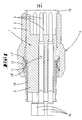
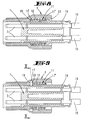
- the plug is in Essentially from a plastic core part 1, which with its free end 2 forms an insert part, which in an insertion cavity a mating connector part, not shown, can be inserted.
- the contact elements designated by the reference number 3 which in the exemplary embodiment are formed by pins in a conductive connection with corresponding ones Contact elements of the mating connector part.
- the contact elements 3 are via clamping sleeves 15 or the like connected to wires 9 of a cable 8.
- the cable 8 has a screen 7 which is electrically conductive with a guide section 6 of the Core part 1 surrounding sleeve 10 is connected.
- the screen is between the sleeve 10 and a clamping shell 16.
- the clamping shell 16 is surrounded by a plastic encapsulation 17.
- the sleeve 10 can be placed on the guide section 6 assigned to the core part 1 be pressed on. However, it is also possible to injection-mold the entire core part 1 produce, wherein the sleeve 10 is part of the mold.
- the front end of the insertion section 2 forms a bead 18.
- a cap screw 4 can be mounted on this bead. It is through Exerting a force pushed over the bead and locked behind it.
- the Cap screw 4 has an external thread 5, which in a corresponding Mating thread of the mating connector part can be screwed in.
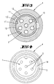
- the cap screw 4 overlaps a portion of the sleeve 10. Inside this overlapping partial area has the inner wall of the cap screw 4 an annular recess 12. In this annular recess 12 lies a spring washer 11 bent from a leaf spring. This spring ring has a circumferential recess (see FIG. 3).
- the cross section of the spring ring 11 is V-shaped, the two edge edges 11 "of the spring ring 11 on the floor Support 12 'of the ring recess 12.
- the apex 11 'of the spring ring 11 rests under spring tension on the outer wall of the sleeve 10. hereby is in each axial position of the cap screw 4 to the sleeve 10 conductive connection between sleeve 10 and union 4 given.
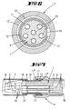
- FIGS. 5 and 6 has at least the portion of the sleeve 10 on which the spring ring 11 in the screwed position is a corrugation or corrugation.
- the apex 11 'of the spring ring has a corresponding corrugation 13.
- the wave crests of the waves 13 of the spring ring 11 can be in the Depress the corrugation 14 of the sleeve 10.
- the spring element 11 is as Helical compression spring designed. One end 11 'of the helical compression spring lies against a step 19 of the ring recess 12. The other end 11 "of the spring element 11 is supported on a shoulder 22 which is assigned to the sleeve 10 is, from. If the cap 4 is displaced in the axial direction relative to the sleeve 10, so the spring element 11 relaxes or tensions, the end 11 'in electrical Lead connection to stage 19 and the other end 11 "in conductive connection to shoulder 22 remains.
- the inner wall has the cap 4, which is directed towards the ring recess 12, a niche in the form of another ring recess 20.
- this ring recess 20 is a radially projecting section 11 'of the coil spring 11.
- the other end 11 "of the coil spring is in contact with the Outer wall of the sleeve 10.
- the Coil spring 11 is not necessarily a compression spring.
- the turns of the Coil spring 11 can also be close together. But it is preferred that the turns of the coil spring forming the end 11 "are tight on the Apply sleeve 10. It need not only be the turns 11 "that are close to the Apply sleeve 10. It can be all turns of the coil spring 10.
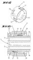
- the spring element a sheet metal sleeve.
- Contact tongues 21 are cut radially outward from the sheet. These contact tongues 21 are in contact with the inner wall of throw 4. This will make contact between the spring element 11 and cap 4 produced.
- the contact between spring element 11 and sleeve 10 is formed in this embodiment of features 23. These features 23 are made from the spring element 11
- the sheet metal part is marked radially inwards and lies in contact with the system the outer surface of the sleeve 10.
- the axial movement of the Spring element 11 is also in this embodiment by a shoulder 22, which is integrally formed on the sleeve 10.
- the spring element 11 also formed by a sheet metal part which is shaped into a sleeve.
- contact tongues 21 protrude both radially outside to come into contact with the cap 4, as well as in the form of the contact tongues 21 'radially inward to come into contact with the sleeve 10.
- the contact to the cap 4 is made by projecting radially outwards Contact tongues 21 in contact with the sleeve 10 by projecting radially inwards Contact tongues 21 'ensured.
Abstract
Description
Die Erfindung betrifft ein Steckerteil einer Steckverbindung mit einem Kernteil aus Kunststoff, der einen Einsteckabschnitt ausbildet zum Einstecken in eine Einstecköffnung eines Gegensteckteiles, wobei Kontaktelemente des Kernteiles mit Gegenkontaktelementen der Einstecköffnung in eine elektrisch leitende Verbindung zueinander treten, mit einem dem Kernteil zugeordneten Überwurf aus Metall, der ein Gewinde aufweist zum in Verbindung bringen mit einem Gegengewinde des Gegensteckerteils, wobei ein rückwärtig sich dem Einsteckabschnitt anschließender Führungsabschnitt des Kernteiles eine elektrisch leitende, mit einem Schirm eines Kabels in Verbindung bringbare Hülse trägt, die in elektrischer Leitverbindung zum Überwurf steht.The invention relates to a plug part of a plug connection with a core part made of plastic, which forms an insertion section for insertion into a Insertion opening of a mating plug part, contact elements of the core part with mating contact elements of the insertion opening in an electrically conductive Connect to each other with a cap assigned to the core part made of metal, which has a thread to connect to a Mating thread of the mating connector part, with a rearward the insertion section subsequent guide section of the core part an electrical carries conductive sleeve which can be connected to a shield of a cable, which is in electrical connection with the union.
Der Erfindung liegt die Aufgabe zugrunde, ein gattungsgemäßes Steckerteil im Hinblick auf eine höhere Betriebssicherheit zu verbessern.The invention is based, a generic connector part in the task To improve with a view to higher operational safety.
Gelöst wird die Aufgabe durch die in den Ansprüchen angegebene Erfindung.The object is achieved by the invention specified in the claims.
Der Anspruch 1 sieht zunächst und im Wesentlichen vor, dass die Leitverbindung
zwischen Hülse und Überwurf mittels eines ringförmigen Federelementes,
bspw. in Form eines Federringes erfolgt. Dieses Federelement stützt sich
bevorzugt in einer Ringaussparung der Innenwandung des Überwurfs ab. Zufolge
einer Federvorspannung liegen dann andere Abschnitte des Federelementes
federkraftbeaufschlagt auf der Hülse auf. Unabhängig von der axialen Stellung
des Überwurfs zur Hülse wird über das Federelement die elektrische Leitverbindung
zwischen Hülse und Überwurf sichergestellt. Die Montage des
Steckers mit dem Gegensteckerteil erfolgt dadurch, dass der Einsteckabschnitt
des Steckers in die Einsteckhöhlung des Gegensteckerteils eingeschoben wird.
Dabei treten die Kontaktelemente in elektrischen Kontakt zu den Gegenkontaktelementen.
Bei den Kontaktelementen kann es sich um Stifte oder Hülsen
handeln. Beim Einstecken des Einsteckabschnittes des Steckers in die Einsteckhöhlung
des Gegensteckerteiles kann sich - falls nicht vorher schon geschehender
Überwurf in Achsrichtung gegenüber dem Kernteil verschieben. Die Innenwandung
der Einsteckhülse des Gegensteckerteiles ist aus Metall und weist
ein Innengewinde auf. In dieses Innengewinde kann der Überwurf eingeschraubt
werden. Hierzu besitzt der Überwurf ein Außengewinde. Beim Einstecken
des Einsteckabschnittes in die Einsteckhöhlung treten die Gewindegänge
von Außengewinde und Innengewinde derart gegeneinander, dass sich der
Überwurf gegebenenfalls axial gegenüber dem Kernteil verlagert. Hierbei gleitet
der Federring über die Hülse. Beim Einschrauben des Überwurfes in das
Innengewinde verlagert sich die Berührungsstelle des Federringes auf der Hülse
in einer Spiralkurve hin zum freien Ende des Steckerteils. Während des gesamten
Einschraubvorganges besteht eine leitende, wackelfreie Verbindung
zwischen dem Innengewinde des Gegensteckerteiles und der Hülse des Stekkerteiles,
welche elektrisch leitend mit dem Schirm des Kabels verbunden ist.
Dadurch, dass der Federring in einer Ringaussparung in der Innenwandung
des Überwurfs liegt, ist er gegen Verlieren gesichert. Der Federring hat vorzugsweise
eine V-Form. Er kann aber auch eine Querschnittsform besitzen, die
dem eines U oder einer Welle entspricht. Er liegt mit seinen Endkanten berührend
auf dem Boden der Ringaussparung und liegt mit einer gewissen Vorspannung
mit seinem Scheitel auf der Außenwandung der Hülse. Der Ring ist
nicht geschlossen, sondern bildet einen Spalt. In einer bevorzugten Weiterbildung
der Erfindung ist der Bereich des Scheitels in Umfangsrichtung gewellt.
Der Abschnitt der Hülse, auf den der Federring in der verschraubten Stellung
zum Liegen kommt, ist ebenfalls gewellt. Hierdurch ergibt sich eine Rüttelsicherheit,
da zur Drehbetätigung des Überwurfs eine gewisse Rastkraft überwunden
werden muss. Die Wellung auf der Hülse kann durch Rippen bzw.
Nuten erreicht werden, die sich in Umfangsrichtung abwechseln. In der eingeschraubten Stellung greifen die beiden Wellungen ineinander.Grooves can be achieved, which alternate in the circumferential direction. In the screwed Position, the two corrugations interlock.
Bei einer Variante der Erfindung ist vorgesehen, dass das Federelement von einer Schraubenfeder, insbesondere Schraubendruckfeder, ausgebildet ist. Ist das Federelement als Schraubenfeder ausgebildet, so kann es ebenfalls in einer Ringaussparung zwischen Überwurf und Hülse angeordnet sein. Dabei kann sich ein Ende der Schraubendruckfeder an einer Stufe dieser Ringaussparung abstützen. Das andere Ende der Schraubendruckfeder kann sich an einer Schulter der Hülse abstützen. Wird der Überwurf gegenüber der Hülse verschoben, so bleibt die elektrische Verbindung zwischen der Hülse und dem Überwurf bestehen, lediglich die Schraubendruckfeder wird gespannt oder entspannt sich. In einer Variante ist vorgesehen, dass ein Ende der Schraubendruckfeder oder ein Bereich der Schraubendruckfeder radial absteht. Dieses radial abstehende Ende oder der radial abstehende Bereich der Schraubendruckfeder kann in eine Nische, bspw. eine weitere, abgestufte Ringaussparung eintreten. Dadurch ist die Schraubendruckfeder axial an den Überwurf gefesselt. Bei dieser Variante braucht die Schraubenfeder nicht unbedingt eine Druckfeder zu sein. Die Windungen der Schraubenfeder können auch eng gewickelt sein. Der Kontakt zur Hülse ist dann ein gleitender Kontakt der Windungen des anderen Endes der Schraubenfeder. Diese Windungen der Schraubenfeder liegen eng auf der Außenmantelfläche der Hülse an. Zur Montage der Schraubenfeder auf der Hülse muss dann dieser Gleitverbindung erzeugende Abschnitt der Schraubenfeder geringfügig aufgeweitet werden. In einer Weiterbildung der Erfindung ist vorgesehen, dass das Federelement als Blechhülse ausgebildet ist. Von dieser Blechhülse gehen Federzungen aus. Diese Federzungen erstrecken sich in Radialrichtung nach innen und/oder außen. Auch hier kann vorgesehen sein, dass das Federelement von einer Schulter der Hülse in Achsrichtung gefesselt ist. In einer Alternative zu den Kontaktzungen können die Kontakte auch von Ausprägungen ausgebildet werden. Vorzugsweise handelt es sich bei den Ausprägungen um einwärts gerichtete Ausprägungen, die in Kontakt treten zur Hülse. Die Kontaktzungen können sich in Achsrichtung erstrecken. Es ist aber auch vorgesehen, dass sich die Kontaktzungen in Umfangsrichtung erstrecken. In Umfangsrichtung können sich radial nach außen und radial nach innen gerichtete Kontaktzungen abwechseln. Auch in Achsrichtung können radial auswärts gerichtete Zungen radial einwärts gerichteten Zungen gegenüberliegen.In a variant of the invention it is provided that the spring element of a helical spring, in particular helical compression spring, is formed. is the spring element is designed as a coil spring, so it can also in a Ring recess between the union and sleeve can be arranged. It can one end of the helical compression spring at one step of this ring recess support. The other end of the compression coil spring can be on one shoulder support the sleeve. If the cap is moved relative to the sleeve, so the electrical connection between the sleeve and the cap remains exist, only the helical compression spring is tensioned or relaxed yourself. In one variant it is provided that one end of the helical compression spring or an area of the helical compression spring protrudes radially. This radially protruding End or the radially protruding area of the helical compression spring can enter a niche, for example a further, stepped ring recess. Thereby the helical compression spring is axially tied to the union. At this Variant, the coil spring does not necessarily have to be a compression spring. The turns of the coil spring can also be tightly wound. The contact to the sleeve is then a sliding contact of the turns of the other end the coil spring. These turns of the coil spring are tight the outer surface of the sleeve. To mount the coil spring on the The sleeve must then have this sliding connection producing section of the coil spring be expanded slightly. In a further development of the invention provided that the spring element is designed as a sheet metal sleeve. Of this Sheet metal sleeve go out spring tongues. These spring tongues extend in the radial direction inside and / or outside. It can also be provided here that the spring element is bound by a shoulder of the sleeve in the axial direction. In As an alternative to the contact tongues, the contacts can also have forms be formed. It is preferably in the forms around inward-looking features that come into contact with the sleeve. The contact tongues can extend in the axial direction. It is also provided that the contact tongues extend in the circumferential direction. In The circumferential direction can be directed radially outwards and radially inwards Alternate contact tongues. Even in the axial direction can be radially outward directed tongues opposite radially inward tongues.
Ausführungsbeispiele werden nachfolgend anhand beigefügter anhand beigefügter Zeichnungen erläutert. Es zeigen:
- Fig. 1
- einen Schnitt durch einen Teil eines ersten Ausführungsbeispiels der Erfindung;
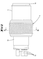
- Fig. 2
- den in Fig. 1 dargestellten Teil einer Seitenansicht;
- Fig. 3
- einen Schnitt gemäß der Linie III - III in Fig. 2;
- Fig. 4
- eine Frontalansicht auf den Stecker;
- Fig. 5
- ein zweites Ausführungsbeispiel der Erfindung in einer Darstellung ähnlich Fig. 1;
- Fig. 6
- eine Schnittdarstellung gemäß der Linie VI - VI in Fig. 5;
- Fig. 7
- ein drittes Ausführungsbeispiel der Erfindung in einer Darstellung gemäß Fig. 1;
- Fig. 8
- ein weiteres Ausführungsbeispiel der Erfindung in einer Darstellung gemäß Fig. 1;
- Fig. 9
- ein weiteres Ausführungsbeispiel der Erfindung in einer Darstellung gemäß Fig. 1;
- Fig. 10
- den Schnitt gemäß der Linie X - X;
- Fig. 11
- ein weiteres Ausführungsbeispiel in einer Darstellung gemäß Fig. 1, jedoch vergrößert;
- Fig. 12
- ein Federelement in perspektivischer Darstellung gehörend zum Ausführungsbeispiel gemäß Fig. 11;
- Fig. 13
- ein weiteres Ausführungsbeispiel in einer vergrößerten Darstellung gemäß Fig. 1;
- Fig. 14
- das Federelement zum Ausführungsbeispiel gemäß Fig. 13 in vergrößerter Darstellung;
- Fig. 15
- ein weiteres Ausführungsbeispiel gemäß Fig. 1 in einer vergrößerten Darstellung;
- Fig. 16
- einen Schnitt gemäß der Linie XVI - XVI in Fig. 15 und
- Fig. 17
- die perspektivische Darstellung eines Federelementes gehörend zum
Ausführungsbeispiel der Fig. 15
und 16.
- Fig. 1
- a section through part of a first embodiment of the invention;
- Fig. 2
- the part of a side view shown in Fig. 1;
- Fig. 3
- a section along the line III - III in Fig. 2;
- Fig. 4
- a front view of the connector;
- Fig. 5
- a second embodiment of the invention in a representation similar to FIG. 1;
- Fig. 6
- a sectional view taken along the line VI - VI in Fig. 5;
- Fig. 7
- a third embodiment of the invention in a representation of FIG. 1;
- Fig. 8
- a further embodiment of the invention in a representation according to FIG. 1;
- Fig. 9
- a further embodiment of the invention in a representation according to FIG. 1;
- Fig. 10
- the section along the line X - X;
- Fig. 11
- a further embodiment in a representation of FIG 1, but enlarged.
- Fig. 12
- a spring element in a perspective view belonging to the embodiment of FIG. 11;
- Fig. 13
- another embodiment in an enlarged view of FIG. 1;
- Fig. 14
- the spring element to the embodiment of FIG 13 in an enlarged view.
- Fig. 15
- another embodiment of FIG 1 in an enlarged view.
- Fig. 16
- a section along the line XVI - XVI in Fig. 15 and
- Fig. 17
- the perspective view of a spring element belonging to the embodiment of FIGS. 15 and 16.
Bei dem in den Fig. 1 bis 6 dargestellten Ausführungsbeispiel sind nur für die
Erläuterung der Erfindung wesentliche Teile dargestellt. Der Stecker besteht im
Wesentlichen aus einem aus Kunststoff bestehenden Kernteil 1, welches mit
seinem freien Ende 2 ein Einsteckteil ausbildet, welches in eine Einsteckhöhlung
eines nicht dargestellten Gegensteckerteils eingesteckt werden kann. Bei dem
Einstecken des Einsteckabschnittes 2 in die entsprechende Einsteckhöhlung treten
die mit der Bezugsziffer 3 bezeichneten Kontaktelemente, die im Ausführungsbeispiel
von Stiften gebildet sind, in eine leitende Verbindung mit entsprechenden
Kontaktelementen des Gegensteckerteils.In the embodiment shown in FIGS. 1 to 6 are only for the
Explanation of the invention shown essential parts. The plug is in
Essentially from a
Die Kontaktelemente 3 sind, wie in der Fig. 7 dargestellt, über Klemmhülsen 15
oder dergleichen mit Adern 9 eines Kabels 8 verbunden. Das Kabel 8 besitzt
einen Schirm 7, der elektrisch leitend mit einer einen Führungsabschnitt 6 des
Kernteiles 1 umgebenden Hülse 10 verbunden ist. Beim Ausführungsbeispiel
gemäß Fig. 7 liegt der Schirm zwischen Hülse 10 und einer Klemmschale 16.
Die Klemmschale 16 ist von einer Kunststoffumspritzung 17 umgeben. Es sind
aber auch andere Möglichkeiten denkbar, um den Schirm 7 in eine Leitverbindung
zur Hülse 10 zu bringen.As shown in FIG. 7, the
Die Hülse 10 kann auf den dem Kernteil 1 zugeordneten Führungsabschnitt 6
aufgepreßt werden. Es ist aber auch möglich, das gesamte Kernteil 1 im Spritzgussverfahren
herzustellen, wobei die Hülse 10 Teil der Form ist.The
Das vordere Ende des Einsteckabschnittes 2 bildet einen Wulst 18 aus. Über
diesen Wulst kann eine Überwurfschraube 4 montiert werden. Sie wird durch
Ausübung einer Kraft über den Wulst geschoben und verrastet dahinter. Die
Überwurfschraube 4 besitzt ein Außengewinde 5, welches in ein entsprechendes
Gegengewinde des Gegensteckerteiles einschraubbar ist. Die Überwurfschraube
4 überlappt mit einem Teilbereich die Hülse 10. Innerhalb dieses
überlappenden Teilbereiches besitzt die Innenwandung der Überwurfschraube
4 eine ringförmige Aussparung 12. In dieser ringförmigen Aussparung 12 liegt
ein aus einer Blattfeder gebogener Federring 11 ein. Dieser Federring besitzt
eine Umfangsaussparung (vgl. Fig. 3). Der Querschnitt des Federrings 11 ist V-förmig,
wobei sich die beiden Randkanten 11" des Federringes 11 auf dem Boden
12' der Ringaussparung 12 abstützen. Der Scheitel 11' des Federringes 11
liegt unter Federvorspannung auf der Außenwandung der Hülse 10 auf. Hierdurch
ist in jeder axialen Stellung der Überwurfschraube 4 zur Hülse 10 eine
leitende Verbindung zwischen Hülse 10 und Überwurf 4 gegeben.The front end of the
In einer Weiterbildung der Erfindung, die in den Fig. 5 und 6 dargestellt ist,
besitzt zumindest der Abschnitt der Hülse 10, auf welchen der Federring 11 in
der verschraubten Stellung liegt, eine Riffelung bzw. Wellung. Im Ausführungsbeispiel
wird diese Riffelung bzw. Wellung von in Achsrichtung sich erstreckenden
kurzen Nuten 14 ausgebildet, die in Umfangsrichtung nebeneinander
liegen. Der Scheitel 11' des Federrings besitzt eine entsprechende Wellung
13. Die Wellenberge der Wellen 13 des Federrings 11 können dabei in die
Vertiefungen der Wellung 14 der Hülse 10 eintreten. Um den Überwurf 4 gegenüber
der Hülse 10 zu drehen, muss jedesmal eine geringfügige Rastkraft
überwunden werden. Dies führt zu einer Rüttelsicherung.In a further development of the invention, which is shown in FIGS. 5 and 6,
has at least the portion of the
Bei dem in Fig. 8 dargestellten Ausführungsbeispiel ist das Federelement 11 als
Schraubendruckfeder ausgebildet. Das eine Ende 11' der Schraubendruckfeder
liegt an einer Stufe 19 der Ringaussparung 12 an. Das andere Ende 11" des Federelementes
11 stützt sich an einer Schulter 22, die der Hülse 10 zugeordnet
ist, ab. Wird der Überwurf 4 in Achsrichtung gegenüber der Hülse 10 verlagert,
so entspannt oder spannt sich das Federelement 11, wobei das Ende 11' in elektrischer
Leitverbindung zur Stufe 19 und das andere Ende 11" in leitender Verbindung
zur Schulter 22 bleibt. In the embodiment shown in Fig. 8, the
Bei dem in den Fig. 9 und 10 dargestellten Ausführungsbeispiel besitzt die Innenwandung
des Überwurfs 4, welcher zur Ringaussparung 12 gerichtet ist,
eine Nische in Form einer weiteren Ringaussparung 20. In dieser Ringaussparung
20 liegt ein radial abstehender Abschnitt 11' der Schraubenfeder 11 ein.
Das andere Ende 11" der Schraubenfeder liegt in berührender Anlage an der
Außenwandung der Hülse 10. Bei diesem Ausführungsbeispiel muss die
Schraubenfeder 11 nicht unbedingt eine Druckfeder sein. Die Windungen der
Schraubenfeder 11 können auch eng aneinander liegen. Es ist aber bevorzugt,
dass die das Ende 11" ausbildenden Windungen der Schraubenfeder eng an der
Hülse 10 anliegen. Es müssen nicht nur die Windungen 11" sein, die eng an der
Hülse 10 anliegen. Es können alle Windungen der Schraubenfeder 10 sein. Wesentlich
bei diesem Ausführungsbeispiel ist nur, dass die Schraubenfeder 11
sowohl elektrisch leitend als auch axial unverschieblich dem Überwurf 4 zugeordnet
ist. Es ist also nicht erforderlich, dass, wie in der Figur 9 dargestellt, die
Ringaussparung 20 zur Aufnahme eines Abschnittes 11' der Schraubenfeder
unmittelbar der Stufe 19 zugeordnet ist. Diese Ringaussparung 20 kann auch an
dem gegenüberliegenden Ende der die Feder 11 aufnehmenden Ringaussparung
12 liegen.In the embodiment shown in FIGS. 9 and 10, the inner wall has
the
Bei dem in Figur 11 dargestellten Ausführungsbeispiel ist das Federelement
eine Blechhülse. Aus dem Blech sind nach radial außen Kontaktzungen 21 freigeschnitten.
Diese Kontaktzungen 21 liegen in berührender Anlage an der Innenwandung
des Überwurfs 4 an. Dadurch wird der Kontakt zwischen Federelement
11 und Überwurf 4 hergestellt. Der Kontakt zwischen Federelement 11
und Hülse 10 wird bei diesem Ausführungsbeispiel von Ausprägungen 23 ausgebildet.
Diese Ausprägungen 23 sind aus dem das Federelement 11 bildenden
Blechteil nach radial innen ausgeprägt und liegen in berührender Anlage auf
der Außenmantelfläche der Hülse 10. Die axiale Bewegungsmöglichkeit des
Federelementes 11 wird auch bei diesem Ausführungsbeispiel durch eine Schulter
22, die der Hülse 10 angeformt ist, begrenzt.In the embodiment shown in Figure 11 is the spring element
a sheet metal sleeve. Contact
Bei dem in Figur 13 dargestellten Ausführungsbeispiel wird das Federelement
11 ebenfalls von einem Blechteil gebildet, welches zu einer Hülse geformt ist.
Bei diesem Ausführungsbeispiel ragen Kontaktzungen 21 sowohl nach radial
außen, um in Kontakt mit dem Überwurf 4 zu treten, als auch in Form der Kontaktzungen
21' nach radial innen, um mit der Hülse 10 in Kontakt zu treten. Bei
diesem Ausführungsbeispiel sind in Umfangsrichtung jeweils drei nach radial
außen ragende Kontaktzungen 21 und drei nach radial innen ragende Kontaktzungen
21' vorgesehen. In Umfangsrichtung wechseln die radial auswärts gerichteten
Kontaktzungen 21 sich mit den nach radial innen ragenden Kontaktzungen
21' ab.In the embodiment shown in Figure 13, the
Bei dem in den Figuren 15 bis 17 dargestellten Ausführungsbeispiel wird das
Federelement 11 ebenfalls von einem hülsenförmigen Blechteil ausgebildet.
Auch hier wird der Kontakt zum Überwurf 4 durch radial auswärts ragende
Kontaktzungen 21 unter Kontakt zur Hülse 10 durch radial einwärts ragende
Kontaktzungen 21' sichergestellt. Anders als bei dem zuvor beschriebenen Ausführungsbeispiel
erstrecken sich die Zungen 21, 21' aber in Umfangsrichtung
des Federelementes 11. Auch hier wechseln - allerdings in Umfangsrichtung
insgesamt vier - radial auswärts ragende Kontaktzungen 21 sich mit radial einwärts
ragenden Kontaktzungen 21' ab. In Achsrichtung liegt jeweils eine radial
einwärts gerichtete Kontaktzunge 21 neben einer radial auswärts gerichteten
Kontaktzunge 21.In the exemplary embodiment shown in FIGS. 15 to 17, this is
Alle offenbarten Merkmale sind (für sich) erfindungswesentlich. In die Offenbarung der Anmeldung wird hiermit auch der Offenbarungsinhalt der zugehörigen/ beigefügten Prioritätsunterlagen (Abschrift der Voranmeldung) vollinhaltlich mit einbezogen, auch zu dem Zweck, Merkmale dieser Unterlagen in Ansprüche vorliegender Anmeldung mit aufzunehmen.All of the features disclosed are (in themselves) essential to the invention. In the revelation of the registration, the disclosure content of the associated / attached priority documents (copy of the pre-registration) in full included, also for the purpose, characteristics of these documents in To include claims of the present application.
Claims (12)
Applications Claiming Priority (4)
| Application Number | Priority Date | Filing Date | Title |
|---|---|---|---|
| DE10318509 | 2003-04-24 | ||
| DE10318509 | 2003-04-24 | ||
| DE10356044A DE10356044A1 (en) | 2003-04-24 | 2003-12-01 | Plug part of a plug connection |
| DE10356044 | 2003-12-01 |
Publications (2)
| Publication Number | Publication Date |
|---|---|
| EP1471610A2 true EP1471610A2 (en) | 2004-10-27 |
| EP1471610A3 EP1471610A3 (en) | 2005-12-21 |
Family
ID=32963535
Family Applications (1)
| Application Number | Title | Priority Date | Filing Date |
|---|---|---|---|
| EP04008036A Withdrawn EP1471610A3 (en) | 2003-04-24 | 2004-04-02 | Plug part for a plug connector |
Country Status (1)
| Country | Link |
|---|---|
| EP (1) | EP1471610A3 (en) |
Cited By (6)
| Publication number | Priority date | Publication date | Assignee | Title |
|---|---|---|---|---|
| WO2008061572A2 (en) * | 2006-03-16 | 2008-05-29 | Escha Bauelemente Gmbh | Shielded connector and method for producing the same |
| US7406017B2 (en) | 2003-06-12 | 2008-07-29 | Samsung Electronics Co., Ltd. | Apparatus for reproducing data from information storage medium having multiple storage layers with optimal power control (OPC) areas and buffer areas |
| EP2051340A1 (en) * | 2007-10-19 | 2009-04-22 | ITT Manufacturing Enterprises, Inc. | Electrical connector |
| WO2015172866A1 (en) * | 2014-05-14 | 2015-11-19 | Eisele Pneumatics Gmbh & Co. Kg | Connection unit for a coupling device, in particular a multiple coupling |
| CN110854580A (en) * | 2019-11-28 | 2020-02-28 | 瓯锟科技温州有限公司 | Spring type socket with reliable and lasting reset function |
| DE102015212660B4 (en) * | 2015-07-07 | 2020-10-08 | Volkswagen Aktiengesellschaft | Charging plug |
Citations (9)
| Publication number | Priority date | Publication date | Assignee | Title |
|---|---|---|---|---|
| US3275970A (en) * | 1964-02-06 | 1966-09-27 | United Carr Inc | Connector |
| GB2066591A (en) * | 1979-12-13 | 1981-07-08 | Bunker Ramo | Electrical connector shell and method of making same |
| US4593964A (en) * | 1983-03-15 | 1986-06-10 | Amp Incorporated | Coaxial electrical connector for multiple outer conductor coaxial cable |
| US4598959A (en) * | 1983-11-04 | 1986-07-08 | International Telephone And Telegraph Corporation | Electrical connector grounding ring |
| DE4307728A1 (en) * | 1993-03-11 | 1994-09-15 | Contact Gmbh | Plug connector |
| DE4412173A1 (en) * | 1993-04-08 | 1994-10-13 | Amphenol Tuchel Elect | Round plug connector having a filter |
| GB2284510A (en) * | 1993-12-04 | 1995-06-07 | Interconnectron Gmbh | Electrical connector |
| US5478254A (en) * | 1994-10-03 | 1995-12-26 | Rolls-Royce, Plc | Electrical connector |
| US5823803A (en) * | 1996-06-17 | 1998-10-20 | Conxall Corporation | Electrical cable connector |
-
2004
- 2004-04-02 EP EP04008036A patent/EP1471610A3/en not_active Withdrawn
Patent Citations (9)
| Publication number | Priority date | Publication date | Assignee | Title |
|---|---|---|---|---|
| US3275970A (en) * | 1964-02-06 | 1966-09-27 | United Carr Inc | Connector |
| GB2066591A (en) * | 1979-12-13 | 1981-07-08 | Bunker Ramo | Electrical connector shell and method of making same |
| US4593964A (en) * | 1983-03-15 | 1986-06-10 | Amp Incorporated | Coaxial electrical connector for multiple outer conductor coaxial cable |
| US4598959A (en) * | 1983-11-04 | 1986-07-08 | International Telephone And Telegraph Corporation | Electrical connector grounding ring |
| DE4307728A1 (en) * | 1993-03-11 | 1994-09-15 | Contact Gmbh | Plug connector |
| DE4412173A1 (en) * | 1993-04-08 | 1994-10-13 | Amphenol Tuchel Elect | Round plug connector having a filter |
| GB2284510A (en) * | 1993-12-04 | 1995-06-07 | Interconnectron Gmbh | Electrical connector |
| US5478254A (en) * | 1994-10-03 | 1995-12-26 | Rolls-Royce, Plc | Electrical connector |
| US5823803A (en) * | 1996-06-17 | 1998-10-20 | Conxall Corporation | Electrical cable connector |
Cited By (10)
| Publication number | Priority date | Publication date | Assignee | Title |
|---|---|---|---|---|
| US7406017B2 (en) | 2003-06-12 | 2008-07-29 | Samsung Electronics Co., Ltd. | Apparatus for reproducing data from information storage medium having multiple storage layers with optimal power control (OPC) areas and buffer areas |
| WO2008061572A2 (en) * | 2006-03-16 | 2008-05-29 | Escha Bauelemente Gmbh | Shielded connector and method for producing the same |
| WO2008061572A3 (en) * | 2006-03-16 | 2008-12-31 | Escha Bauelemente Gmbh | Shielded connector and method for producing the same |
| US7976341B2 (en) | 2006-03-16 | 2011-07-12 | Escha Bauelemente Gmbh | Shielded connector and method for producing the same |
| EP2051340A1 (en) * | 2007-10-19 | 2009-04-22 | ITT Manufacturing Enterprises, Inc. | Electrical connector |
| WO2015172866A1 (en) * | 2014-05-14 | 2015-11-19 | Eisele Pneumatics Gmbh & Co. Kg | Connection unit for a coupling device, in particular a multiple coupling |
| CN106463864A (en) * | 2014-05-14 | 2017-02-22 | 艾泽勒气动有限责任两合公司 | Connection unit for a coupling device, in particular a multiple coupling |
| US9935386B2 (en) | 2014-05-14 | 2018-04-03 | Eisele Pneumatics Gmbh & Co. Kg | Connection unit for a coupling device, in particular a multiple coupling |
| DE102015212660B4 (en) * | 2015-07-07 | 2020-10-08 | Volkswagen Aktiengesellschaft | Charging plug |
| CN110854580A (en) * | 2019-11-28 | 2020-02-28 | 瓯锟科技温州有限公司 | Spring type socket with reliable and lasting reset function |
Also Published As
| Publication number | Publication date |
|---|---|
| EP1471610A3 (en) | 2005-12-21 |
Similar Documents
| Publication | Publication Date | Title |
|---|---|---|
| DE69734971T2 (en) | coaxial cable | |
| EP3047544B1 (en) | Contact washer and plug connector | |
| DE19846440A1 (en) | Connector for coaxial cable with ring-corrugated outer conductor | |
| DE10326526A1 (en) | Coaxial cable connector has an integrated flexible sealing ring retained in connector housing and shaped to fit securely against cable | |
| DE4226904C2 (en) | Crimp sleeve | |
| EP2601718B1 (en) | Illuminating device and sealing element therefor | |
| DE19613228A1 (en) | Plug part for electric plug connector of line bus | |
| DE202009009807U1 (en) | Tamper-proof cable entry | |
| DE102008036399A1 (en) | data cable | |
| EP0431408A2 (en) | Connector assembly for a multicore cable | |
| WO2019134828A1 (en) | Cable shield contacting device and electric plug connector | |
| WO2014117926A1 (en) | Plug-type connector | |
| EP2515387B1 (en) | Plug | |
| EP1471610A2 (en) | Plug part for a plug connector | |
| DE102004012883A1 (en) | Connector for the electrical connection of solar panels | |
| DE3905024A1 (en) | CONNECTING DEVICE FOR ELECTRICAL CABLES | |
| EP2410613B1 (en) | Round plug connector | |
| DE102011050574A1 (en) | terminal connector | |
| EP3183787A1 (en) | Electric device | |
| EP3435494B1 (en) | Connector and use | |
| EP1667284B1 (en) | Contact device for a cable shield | |
| DE10356044A1 (en) | Plug part of a plug connection | |
| DE3302924C3 (en) | Electrical connector | |
| EP1998411A2 (en) | Electric plug connector | |
| DE102016100339B4 (en) | ELECTRICAL CONNECTOR AND ELECTRICAL CONTACT CONNECTION |
Legal Events
| Date | Code | Title | Description |
|---|---|---|---|
| PUAI | Public reference made under article 153(3) epc to a published international application that has entered the european phase |
Free format text: ORIGINAL CODE: 0009012 |
|
| AK | Designated contracting states |
Kind code of ref document: A2 Designated state(s): AT BE BG CH CY CZ DE DK EE ES FI FR GB GR HU IE IT LI LU MC NL PL PT RO SE SI SK TR |
|
| AX | Request for extension of the european patent |
Extension state: AL HR LT LV MK |
|
| PUAL | Search report despatched |
Free format text: ORIGINAL CODE: 0009013 |
|
| AK | Designated contracting states |
Kind code of ref document: A3 Designated state(s): AT BE BG CH CY CZ DE DK EE ES FI FR GB GR HU IE IT LI LU MC NL PL PT RO SE SI SK TR |
|
| AX | Request for extension of the european patent |
Extension state: AL HR LT LV MK |
|
| RIC1 | Information provided on ipc code assigned before grant |
Ipc: 7H 01R 9/03 B Ipc: 7H 01R 13/502 B Ipc: 7H 01R 13/658 A |
|
| AKX | Designation fees paid | ||
| STAA | Information on the status of an ep patent application or granted ep patent |
Free format text: STATUS: THE APPLICATION IS DEEMED TO BE WITHDRAWN |
|
| 18D | Application deemed to be withdrawn |
Effective date: 20060622 |
|
| REG | Reference to a national code |
Ref country code: DE Ref legal event code: 8566 |