EP0431408A2 - Connector assembly for a multicore cable - Google Patents
Connector assembly for a multicore cable Download PDFInfo
- Publication number
- EP0431408A2 EP0431408A2 EP90122342A EP90122342A EP0431408A2 EP 0431408 A2 EP0431408 A2 EP 0431408A2 EP 90122342 A EP90122342 A EP 90122342A EP 90122342 A EP90122342 A EP 90122342A EP 0431408 A2 EP0431408 A2 EP 0431408A2
- Authority
- EP
- European Patent Office
- Prior art keywords
- plug
- housing part
- guide
- core
- arrangement according
- Prior art date
- Legal status (The legal status is an assumption and is not a legal conclusion. Google has not performed a legal analysis and makes no representation as to the accuracy of the status listed.)
- Withdrawn
Links
Images
Classifications
-
- H—ELECTRICITY
- H01—ELECTRIC ELEMENTS
- H01R—ELECTRICALLY-CONDUCTIVE CONNECTIONS; STRUCTURAL ASSOCIATIONS OF A PLURALITY OF MUTUALLY-INSULATED ELECTRICAL CONNECTING ELEMENTS; COUPLING DEVICES; CURRENT COLLECTORS
- H01R13/00—Details of coupling devices of the kinds covered by groups H01R12/70 or H01R24/00 - H01R33/00
- H01R13/46—Bases; Cases
- H01R13/502—Bases; Cases composed of different pieces
-
- H—ELECTRICITY
- H01—ELECTRIC ELEMENTS
- H01R—ELECTRICALLY-CONDUCTIVE CONNECTIONS; STRUCTURAL ASSOCIATIONS OF A PLURALITY OF MUTUALLY-INSULATED ELECTRICAL CONNECTING ELEMENTS; COUPLING DEVICES; CURRENT COLLECTORS
- H01R24/00—Two-part coupling devices, or either of their cooperating parts, characterised by their overall structure
- H01R24/86—Parallel contacts arranged about a common axis
-
- H—ELECTRICITY
- H01—ELECTRIC ELEMENTS
- H01R—ELECTRICALLY-CONDUCTIVE CONNECTIONS; STRUCTURAL ASSOCIATIONS OF A PLURALITY OF MUTUALLY-INSULATED ELECTRICAL CONNECTING ELEMENTS; COUPLING DEVICES; CURRENT COLLECTORS
- H01R13/00—Details of coupling devices of the kinds covered by groups H01R12/70 or H01R24/00 - H01R33/00
- H01R13/46—Bases; Cases
- H01R13/516—Means for holding or embracing insulating body, e.g. casing, hoods
-
- H—ELECTRICITY
- H01—ELECTRIC ELEMENTS
- H01R—ELECTRICALLY-CONDUCTIVE CONNECTIONS; STRUCTURAL ASSOCIATIONS OF A PLURALITY OF MUTUALLY-INSULATED ELECTRICAL CONNECTING ELEMENTS; COUPLING DEVICES; CURRENT COLLECTORS
- H01R13/00—Details of coupling devices of the kinds covered by groups H01R12/70 or H01R24/00 - H01R33/00
- H01R13/58—Means for relieving strain on wire connection, e.g. cord grip, for avoiding loosening of connections between wires and terminals within a coupling device terminating a cable
-
- H—ELECTRICITY
- H01—ELECTRIC ELEMENTS
- H01R—ELECTRICALLY-CONDUCTIVE CONNECTIONS; STRUCTURAL ASSOCIATIONS OF A PLURALITY OF MUTUALLY-INSULATED ELECTRICAL CONNECTING ELEMENTS; COUPLING DEVICES; CURRENT COLLECTORS
- H01R2107/00—Four or more poles
Definitions
- the invention relates to a connector arrangement for a multi-core cable according to the preamble of claim 1.
- Such a connector arrangement is known from EP-A3-0 189 857.
- the contact elements are inserted axially into the receiving channels of the plug core and are held therein by barbs, which prevent a movement direction of the contact elements opposite to the insertion movement.
- a comb is inserted through radial openings at the rear line-side end of the plug part, which engages behind a seal pushed onto the contact elements and represents a second locking of the contact elements.
- Such a connector arrangement is difficult to assemble, especially if it is a miniature connector, since the cable wires for the axial insertion of the contact elements into the receiving channels must have a free length that allows maneuvering, which must later be accommodated in the connector housing.
- the shielding can only contact after plugging it together, which is very complex and makes automatic connector assembly impossible.
- a plug arrangement according to the prior art is difficult to disassemble, for example for repair purposes, since the contact elements do not damage the plug core or the contact element itself difficult or impossible to remove from the plug part.
- each individual contact element can only be inserted into the receiving channels in a very specific position and locked in these. The assembly of such a connector arrangement is thus complex and the disassembly of the individual connector parts is complicated or not possible at all.
- the coupling is made more difficult by the fact that the plug parts must have an aligned rotational position with respect to one another at the start of their insertion movement.
- the invention has for its object to provide a connector assembly of the type mentioned, which is easier to assemble and easier to use.
- the contact or counter-contact elements ie Plug or socket elements
- the respective insertion of the contact elements into the recess can be carried out particularly easily and quickly, since the contact elements do not have to be arranged in a specific position in the recesses.
- a rotation of the contact elements in the direction of their longitudinal axis is therefore not necessary to insert or press the contact elements into the core body. This simplifies both the manufacture and the disassembly of the connector arrangement.
- each recess With the help of the radially outwardly projecting projections narrowing each recess, a simple possibility is created to secure the contact elements against axial movement.
- the pin contacts attached to the free end of the contact elements for example with the aid of crimping technology, enable fully automatic attachment and thus mechanical production.
- a recess corresponding to the projection can be formed particularly easily on the contact element if the pin contacts are arranged at a distance from the insulating jacket end of the individual wires of the cable. With the Striking the pin contacts therefore creates the recess which is advantageous for an axial hold.
- the front section of the plug core facing the opening of the first housing part protrudes axially slightly beyond the pin contacts in the assembled state of the first plug part, since the mating contact elements can thus initially be inserted particularly easily axially into the plug core without the pin contacts having to be gripped around. This allows mutual fixing of the plug cores with very little effort in the axial direction, which additionally simplifies the handling of the plug arrangement.
- the holding claws with a partially cylindrical cross section and the free end of the holding claws as a clamping element, since the inner surface of each holding claw is thus well adapted to the cylindrical outer surface of the cable and can be supported uniformly on the latter.
- the clamping element also enables the cable end to be clamped firmly between, for example, two diametrically opposite holding claws.
- the clamping process can be carried out by spring pretensioning of the individual brackets or by an external force. The cable end is thus securely connected to the plug part at all times. Tearing off the cable is almost impossible during the assembled state.
- the clamping action of the clamping element is further supported by the fact that the clamping elements have a screw thread on their outer surface and that each clamping element has on its inner surface a radially inwardly projecting projection, one of which is towards the free end of each Holding claw connects inclined clamping surface.
- the screw thread enables a permanent clamping effect by simply, releasably fixing the clamping elements on the cable section. With the help of the projection, a good clamping effect is achieved even with low clamping forces, since the projection presses firmly into the cable end.
- the projection also ensures, in connection with the inclined clamping surface, a clamping pressure which is limited in area and thus increased, since this increases with a constant force but a reduced area.
- each thread of the screw thread located on the clamping element with a rising, inclined towards the guide ring and an adjoining radially falling thread flank not only enables screwing but also a fully mechanically latching of an element that presses the free ends of the holding claws towards each other .
- This feature also simplifies the manufacture of a well-supported connector part.
- the clamping ring By means of the clamping ring provided on the end section of the cable, damage to the cable due to excessive pressing forces acting on the clamping element of each holding claw is effectively prevented.
- the clamping ring is attached to the folded back shield of the cable, so that the clamping ring, the fixed supporting claws supported thereon, the guide ring and the first housing part in the sense of a double action also ensure an additional ground connection.
- the shielding can also be pulled back and the clamping ring applied fully automatically. With the additional ground connection to the housing part, an uninterrupted electrical shielding can be achieved.
- each holding claw It is also favorable to provide the clamping ring with a circumferential, radially outwardly extending stop against which the free end of each holding claw rests in an axially supported manner in the installed state.
- the clamping element of each holding claw is not only held firmly on the clamping ring in the radial direction, but also effectively prevents axial displacement of the clamping ring seated on the cable end in the direction of the guide ring.
- the plug part is assembled particularly simply by plugging the core body onto the holding rivet connected to the clamping ring and extending axially away from the end section of the cable, the free end of which is arranged in the central longitudinal axis of the plug part.
- the core body attached to the holding rivet can also be inserted fully mechanically into the plug core and the guide ring.
- the holding rivet which can also be designed as a blind rivet, can be easily expanded, so that the core body and plug core form a unit in which the contact elements are held.
- the plug core of the first plug part is secured against undesired rotation in relation to the first housing part when the Latching projection engages in a counter-latch projecting radially inward in the inner wall of the first housing part.
- the connector part and housing part can therefore only be rotated if the locking projection is also moved out of the counter-locking.
- the locking spring thus enables simple and inexpensive fixing of the plug part in the housing part.
- the part of the holding claws designed as a clamping element and the clamping ring located between them protrude axially at least partially over the first housing part in the assembled state of the first plug part, and an end cap is screwed or snapped onto the screw thread of the clamping elements.
- the housing part is axially fixed to the plug core and via the clamping ring with the cable, on the other hand, an uninterrupted earth connection and thus electrical shielding is ensured via the clamping ring, the end cap, the clamping bracket and the housing part.
- the end cap can also be mechanically snapped onto the clamping element, which further rationalizes the manufacture of the entire plug part.
- the end cap also serves to support the free end of each holding claw axially firmly on the stop of the clamping ring which extends radially outward.
- an axial play is provided between the first housing part and the end cap seated on the clamping element and the clamping ring in the locking position of the locking projection and counter-locking, so that the housing part releases the engagement of the locking projection and counter-locking on the plug core for mutual coupling of the Plug parts can be rotated freely can.
- the axial play preferably corresponds to at least the gripping depth of the locking projection and counter-latch, so that there is almost no axial play between the housing part and the end cap when in their disengaged position.
- Electrical cables are usually provided with a shield, with a ground connection from the shield to the plug part.
- a shield with a ground connection from the shield to the plug part.
- at least the clamping ring, the holding claws, the end cap and the first and second housing parts consist of an electrically conductive material or have a conductive coating.
- the construction of the plug arrangement ensures an uninterrupted ground connection. Additional parts are not required to form the ground connection.
- the respective plug parts are arranged such that they can be plugged into one another.
- Completely shaped straightening and / or guiding elements are dispensed with, so that the manufacturing costs are reduced without having to do without quick and uncomplicated handling of the plug arrangement. Mutual coupling of the connector parts can therefore be carried out without special attention.
- a coupling process can be carried out particularly quickly if each guide rib of the screw thread is part of a 60 ° bayonet screw closure and has an axially extending stop at its rear end. This makes it possible to align the plug core of the first plug part before coupling the plug parts in the first housing part in such a way that the plug cores are closed
- the beginning of the engagement between the guide rib and the guide groove are pluggable to each other. Since the guide ribs are present in any case, it means little manufacturing effort to design each guide rib in the axial direction as a stop. It is particularly advantageous to design the width of the guide rib in the area of the bayonet screw closure and in the area of the stop in an identical manner. With the help of these features, the handling, namely the coupling of the plug arrangement, is therefore simplified without significantly increasing the production costs.
- a particularly effective arrangement is possible if the plug core of the first plug part is arranged between the guide ribs and the guide ring in the region of the stops and the plug core and guide ring are integrally connected to one another. As a result, the latter can be produced in the same process step, which further reduces the number of parts required.
- the guide ring has a cylindrical outer surface with two diametrically opposite recesses, the length and depth of which is designed such that the plug core with its guide ring can be pushed axially past the guide ribs into the opening of the first housing part.
- the connector arrangement provides that in the ready position of the first connector part the connector core is inserted into the first housing part without twisting and one edge of the recesses abuts one side of the stop of each guide rib.
- the first housing part in the closed position of the first plug part, the first housing part is rotated by approximately 60 ° with respect to the first plug part in comparison to the ready position, the other edge of the cutouts resting on the other side of the stop of each guide rib.
- the cutouts thus allow a stop for fixing the housing part in relation to the plug core in a simple manner. This measure considerably simplifies the handling of the connector arrangement.
- the second housing part axially projects slightly beyond the front end of the plug core, which faces the opening of the housing part, or the mating contact elements, in order to effectively protect the mating contact elements of the plug core against damage.
- the respective ends of the plug cores or mating contact elements facing the opening of the housing parts do not rub against each other when the first housing part is rotated on the second housing part.
- each guide groove with two guide surfaces, of which the second guide surface in the direction of rotation is undercut to the front edge of the second housing part in such a way that the entire guide rib can be axially displaced into the guide groove before the screwing movement.
- This axial feed movement indicates to the user that the two connector parts, in particular their connector cores, are aligned with one another and are at least partially already inserted into one another.
- Mutual coupling of the two connector parts is thus possible simply and quickly by sliding the front sections of the guide ribs on the tubular cross-sectional area up to the respective guide groove and by at least partially inserting the two connector parts into one another by means of an axial feed movement before the screwing movement and then are completely pressed into each other by the 60 ° screw connection, so that the contact elements of the first plug part are connected to the mating contact elements of the second plug part.
- Mutual coupling of the connector parts is therefore simple and inexpensive to carry out.
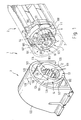
- a connector assembly 1 for a multi-core cable (not shown in Fig. 1) is shown.
- the connector arrangement 1 consists of a first connector part 2 struck on the cable and a second connector part 3 which can be coupled therewith.
- the first connector part 2 has a connector core 4 with receiving channels 5 extending in the direction of insertion for pin contacts 51 of contact elements 6 which are axially inserted into the receiving channels 5 .
- the first connector part 2 also includes an axially fixed first housing part 7, which rotatably surrounds the connector core 4 and is sleeve-shaped, has a cylindrical cross-sectional area and is shown in broken lines in FIG. 1. In his for the second In the area facing the plug part 3, the first housing part 7 has a screw thread 10, of which only the left part is shown in broken lines in FIG. 1.
- the second plug part 3 has a mating contact element 11 and possibly a plug core 12 (not shown) receiving the central grounding pin and a second housing part 13 firmly connected thereto, which is provided with a counter screw thread 14 complementary to the screw thread 10. Only the left part of this counter screw thread can be seen in FIG. 1. 1, the screw thread 10 is designed as an internal thread and the counter screw thread 14 as an external thread.
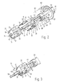
- the plug core 4 of the first plug part 2 has an inner core body 15 with a plurality of channel-shaped recesses 17 arranged in its outer surface 16, as shown in more detail in FIG. 2.
- the recesses 17 extend in the axial direction and are open radially outwards.
- the core body 15 has nine recesses l7.
- Each recess has a partially cylindrical cross-section and a radially inwardly projecting projection 20 which narrows it and is provided approximately in the middle of each recess.
- Each projection 20 has a certain height and a certain length that exceeds the height many times over.
- Each recess 17 preferably has an approximately semicircular cross-sectional area.
- the inner core body 15 On its peripheral surface, the inner core body 15 has an approximately guaderiform guide 21, the right and left front edges 22, 23 of which are chamfered for easier insertion of the core body 15 into the plug core 4.
- the core body 15 has a central through opening 25 concentric with the longitudinal axis 24.
- a cable 26 is shown in the right half of Fig. 2 and e.g. designed as a 9-pin, shielded cable.
- a shield 27 surrounds the entirety of the cable cores 8, has an approximately cylindrical structure and is folded back onto the cable jacket 30 according to FIG. 2.
- FIG. 2 only four electrical conductors designed as cable cores 8 are shown in a simplified manner, at whose respective stripped end 31 the pin-shaped contact elements 6 e.g. are crimped so that there is a recess 33 between them and the end of the insulating jacket 9 each cable wire 8.
- the dimensions of the recess 33, the contact elements 6 and the cable core 8 are dimensioned such that they can be inserted or pressed into the channel-shaped recesses 17 of the inner core body 15, the projection 20 coming to rest in the region of the recess 33.
- the height and length of the projection 20 are therefore preferably slightly smaller than the height and length of the recess 33.
- the cable end of the contact elements 6 is supported on the projection 20 so that the latter can absorb the insertion forces of the connector.
- a clamping ring 34 which has a front cylindrical section 35 and a conically widening rear section 36, is pressed onto the end section of the cable 26, preferably onto the shield 27 which is turned back.
- the front and rear sections 35, 36 are connected to one another in accordance with FIG. 2 such that a circumferential recessed edge 37 is formed in this connection area.
- the clamping ring 34 has a circumferential, radially outwardly extending stop 40 at the rear end of the rear section 36.
- the clamping ring 34 comprises a holding arm 43 which is integrally connected to the front section 35. which extends parallel to and at a distance from the central longitudinal axis 24.
- the front end 44 of the holding arm 43 is bent perpendicular to the longitudinal axis 24 and penetrated by a bore lying concentrically to the longitudinal axis 24.
- a retaining rivet 41 which extends axially away from the end section of the cable 26, is connected to the clamping ring, and the core body 15 can be plugged onto its free end 42 arranged in the central longitudinal axis 24.
- a first hollow rivet section 45 which is arranged concentrically to the longitudinal axis, is inserted into the bore in the front end 44.
- a second hollow rivet section 46 with a smaller diameter is fixedly connected to the front end of the hollow rivet section 45 over a region 47 of smaller diameter. Both hollow rivet sections are penetrated by an expansion pin 50, which carries at its end facing away from the core body 15 an embossing head, not shown, the diameter of which is a few 1/100 mm thicker than the inside diameter of the hollow rivet sections.
- the core body 15 is pushed with its through opening 25 onto the free end 42 of the expansion pin 50 and finally over the hollow rivet section 46 onto the section 45 up to the front end 44 of the holding arm 43.
- the contact elements 6 are pressed with their cable sleeve 32 into the respective channel-shaped recess 17 in FIG. 3 so that the projection 20 comes to rest in the area of the recess 33.
- the pin contact 51 of the contact element 6 projects in the axial direction over the inner core body 15.
- the dashed-dotted first housing part 7 has a front opening 52.
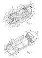
- the inner core body 15 equipped with the contact elements 6 according to FIG. 3 is inserted into the plug core 4 according to FIG. 4 so that the front section 53 of the plug core 4, which faces the opening 52 of the first housing part 7, projects slightly axially beyond the pin contacts 51 (shown in broken lines in FIG. 4).
- the plug core 4 also has an outer guide ring 54 connected integrally therewith, into which the inner core body 15 can be inserted axially to close the recesses 17.
- Partial cylindrical grooves provided on the inner wall of the guide ring 54 complement the recesses 17 to form cylindrical channels in a manner not shown, so that the cable sleeves 32 are completely surrounded.
- these receiving spaces for the cable sleeves 32 are followed by the receiving channels 5, which have a tapered cross-section. The cable sleeves are thus supported on the edges of these channels 5, so that the separating forces are absorbed when the plug connection is released.
- the guide ring 54 comprises a flattened 55, approximately cylindrical sleeve section 56 with two axially extending holding claws 57, 58 connected to it in one piece.
- the holding claws are arranged diametrically opposite one another. Both holding claws have a partially cylindrical cross section and a free end 60, 61, which is designed as a clamping element 62, 63, respectively.
- the clamping elements are each on the end portion of the cable 26 or on the clamping ring 34, the Cable or the clamping ring at least partially encompassing, firmly supported.
- Each clamping element 62, 63 has on its outer surface 64, 65 partial threads 66, 67 complementing one another to form an external thread and on its inner surface 70, 71 a radially inwardly projecting projection 72, 73, to which one of the free ends 60, 61 of each holding claw 57, 58 inclined clamping surface 74, 75 connects.
- the two opposing clamping surfaces 74, 75 form a cone 76 which widens towards the free end of the holding claws.
- the screw thread formed from the partial threads 66, 67 has a plurality of threads 77, each of which has a rising, inclined towards the guide ring 54 and a radial one that follows has a steeply falling thread flank.
- the free ends 60, 61 of the holding claws 57, 58 extend with their clamping surfaces 74, 75 axially up to the stop 40 (cf. FIG. 2) such that the respective projection 72, 73 engages behind the circumferential, recessed edge 37, the respective one Clamping surface 74, 75 is firmly supported on the rear section 36 of the clamping ring 34 and the stop 40 rests on the end faces of the holding claws 62, 63.
- the clamping ring 34 is thus between the free ends of the holding claws.
- the firm engagement of the edge 37 by the projections 72, 73 can e.g. can be achieved by biasing the holding claws towards the longitudinal axis 24. However, it is also possible to press the free ends of the holding claws together with the aid of a force applied radially from the outside.
- a locking spring 81 is pushed onto the sleeve section 56 up to the side 80 of the guide ring 54 facing the holding claws 57, 58, the locking spring 81 of which is vertical extending arms 82, 83 bear against the flats 55.
- the locking spring 81 has on its transverse arms 84, 85 connecting the vertical arms 82, 83 each a locking projection 86, 87 extending axially to the right in FIG. 4.
- the locking spring 81 is shown in solid lines on the right outside of the plug core 4 .
- the locking spring is pushed onto the sleeve section 56 and its flats 55, as shown in broken lines in FIG. 4.
- the first housing part 7 has an inner wall 78, on which a radially inwardly projecting, partially cylindrical lining 88 with a counter-catch 89 for the catch projection 87 of the locking spring 81 is attached (see dashed illustration in FIG. 5).
- the counter-detent is complementary to the detent projection and arranged in the assembled state of the plug part opposite this. Since each latching projection 86, 87 is located approximately vertically above or below the central longitudinal axis 24, the corresponding counter-latches 89 are arranged in the same position. In Fig. 5 only a liner 88 with the counter detent 89 is shown.
- a second lining can be attached diametrically opposite to the first lining on the inner wall 78 of the first housing part 7.
- the first housing part 7 also has an outer side 90, on which four holding ribs 91, each diametrically opposite one another, are arranged offset by 90 ° to one another. 5 only two holding ribs 91 are shown.
- the part of the holding claws 57, 58 designed as a clamping element 62, 63 and the clamping ring 34 located between them are in the assembled state of the first connector part 2 axially at least partially over the first housing part 7.
- An end cap 93 which has an internal thread 92, is screwed or latched onto the partial threads 66, 67 of the clamping elements 62, 63, so that an assembled state according to FIG. 4 is obtained, in which the end cap 93 with its internal thread 92 into the partial threads 66, 67 of the holding claws 57, 58 engages and presses the free end 60, 61 of the holding claws radially inwards onto the clamping ring 34.
- the end cap 93 carries a circumferential bead 94 facing the housing part 7, the outer surface 95 of which tapers conically to center the housing part 7 and the end cap 93 relative to one another when they are joined together.
- the end cap 93 also has a circular stop surface 96 extending perpendicular to the longitudinal axis, which is arranged radially outside the bead 94 and is arranged opposite the outer wall 97 of the housing part 7 in the assembled state, and an inner, radial stop edge (not shown) which is assembled State cooperates with the outer end of the stop 40.
- latching projection 87 and counter-latch 89 In the latching position of latching projection 87 and counter-latch 89, a slight axial play is provided between the first housing part 7 and the end cap 93 seated on the clamping element 62, 63 and the clamping ring 34, which corresponds at least to the depth of engagement of the latching projection and counter-latch.
- the respective latching projection 86, 87 slides on an axially forward-facing surface 98 of the lining 88, so that in this case between the outer wall 97 of the housing part 7 and the stop surface 96 of the end cap 93 there is almost no axial play.
- At least the clamping ring 34, the holding claws 57, 58, the end cap 93 and the first and second housing parts 7, 13 of the plug arrangement 1 consist of one in the cable 26 provided with the shielding 27 electrically conductive material such as Metal, electrically conductive connections or metallized plastic.
- the first housing part 7 comprises two diametrically opposed, radially inwardly projecting guide ribs 100, of which only the left guide rib is shown in FIGS. 1, 4 and 5.
- the two guide ribs are designed as internal threads, are firmly attached to the inner wall 78 of the housing part and represent the screw thread 10.
- the second housing part 13 has a cylindrical outer surface 101, into which guide grooves 102 for the guide ribs 100 are embedded.
- the guide groove 102 therefore form the counter screw thread 14, which is designed as an external thread.
- Each guide rib 100 has a front section 103 facing the opening 52 of the first housing part 7, which in the assembled state of the plug part 2 projects axially beyond the plug core 4 seated in the first housing part 7.
- each guide rib 100 of the screw thread 10 is part of a 60 ° bayonet screw closure 104 and has an axially extending stop 105 at its rear end.
- the width of the guide rib 100 in the region of the bayonet screw closure 104 and in the region of the stop 105 is identical in each case. 1 and 4, the plug core 4 of the first plug part 2 is arranged between the guide ribs 100 and the guide ring 54 in the region of the stops 105.
- the guide ring 54 has a cylindrical outer surface 106 with two diametrically opposite recesses 107, 108, the length and depth of which is formed such that the plug core 4 with its guide ring 54 axially past the guide ribs 100 into the opening 52 of the first housing part 7 or out it can be pushed out. This ensures that the housing part 7 can be moved over the plug core 4.
- the second housing part 13 has an opening 115 facing the first plug part 2 and projects a small amount in the axial direction beyond the front ends facing the opening 115 of the mating contact elements 11 seated on the plug core 12.
- the guide groove 102 is cut into the cylindrical outer surface 101 of the second housing part 13 in such a way that the front section 103 of each guide rib 100 during a rotational movement of the first housing part 7 on the second housing part 13 on the tubular cross-sectional surface 116 of the second housing part 13 without an axial forward movement to can slide to the guide groove 102.
- the guide groove 102 has two guide surfaces 117, 118, of which the second guide surface 118 in the direction of rotation is undercut at 121 at the front edge 120 of the second housing part 13 such that the entire guide rib 100 can be pushed axially into the guide groove 102 before the screwing movement.
- the second connector part 3 has a cap 122, in which the second housing part 13 is inserted axially projecting, so that it forms a body socket with it. But it is also possible to design the second connector part as a built-in socket or as a cable coupling.
- a coding 123, 124 is provided on the upper side of the plug cores 4, 12 according to FIGS. 1 and 4. However, it is also possible to produce the connector arrangement 1 without such coding.
- a triangular marking 125, 126 is attached to the front edge of the first housing part 7 and the cap 122, which marks the different positions of the first housing part 7 with respect to the plug core 4 and the first housing part 7 with respect to indicates throw 122.
- the left mark 125 on the upper side of the first housing part while in the closed position after a 60 ° right turn of the first connector part 2, the right mark 125 stands vertically above the longitudinal axis 24 and thus opposite the mark 126.
- the assembly of the first connector part is described in more detail below.
- the shield 27 of the cable is pushed back and the clamping ring 34 with its front section 35, rear section 36, its holding arm 43 and its front end 44 carrying the holding rivet 41 is pressed firmly onto the folded back shield and the cable end.
- the individual cable cores 8 protrude in the axial direction up to approximately the height of the hollow rivet section 45.
- the contact elements 6 are then struck with their cable sleeves 32 to form a recess 33, so that the pin contacts 51 extend approximately to the level of the hollow rivet section 46.
- the inner core body 15 is pushed with the aid of its through opening 25 onto the free end 42 of the holding rivet 41 up to the hollow rivet section 45 and onto the front end 44 of the holding arm 43.
- the contact elements 6 are inserted or pressed into the channel-shaped recesses 17 of the inner core body 15 from the outside in such a way that the pin contacts 51 protrude beyond the core body and each recess 33 is arranged approximately in the region of the projection 20 provided in each recess (cf. 3).
- the holding rivet 41 can be expanded with the aid of the expansion pin 50 so that the inner core body 15 is firmly connected to the plug core 4 and the pin contacts 51 extend in the receiving channels 5.
- the projections 72, 73 of the clamping elements 62, 63 are arranged at the level of the recessed edge 37 of the front section 35 of the clamping ring 34 (cf. dashed illustration in FIG. 2).
- the embossing head When the expansion pin 50 is pulled through the hollow rivet sections 45, 46, the embossing head initially slides to the region of smaller diameter 47. This is expanded in such a way that the inner core body 15 is already firmly connected to the clamping ring 34. When the expansion pin 50 is pulled further, the hollow rivet section 46 is then expanded in such a way that the plug core 4 sits firmly on it. When the embossing head emerges from the hollow rivet section 46, its end is flared by the flow of material.
- the first housing part 7 is advanced axially via the screw thread 66, 67 of the clamping elements 62, 63 in the direction of the front section 53 of the plug core 4 until the latching projections 86, 87 engage in the counter latches 89 provided in the lining 88.
- the end cap 93 is then screwed or snapped onto the screw thread 66, 67 protruding beyond the first housing part 7 with its internal thread.
- the projections 72, 73 of the clamping elements 62, 63 are radially pressed behind the recessed edge 37 behind the clamping ring 34, the free ends 60, 61 of the holding claws 57, 58 being held axially on the stop 40 of the clamping ring 34.
- the first connector part 2 is thus completely assembled and is in the standby position, in which the edges 110, 111 of the cutout 107, 108 bear against a side 112 of the stop 105.
- the plug core 4 and the first housing part 7 are in the ready position, ie the plug cores 4, 12 are aligned with one another at the beginning of the engagement between the guide rib 100 and the guide groove 102.
- the first plug part 2 is now moved in the direction of the second plug part 3 until the front section 103 of each guide rib 100 bears against the tubular cross-sectional area 116 of the second housing part 13.
- the first housing part 7 can now be rotated together with the plug core 4 due to the engagement of the latching projections 86, 87 with the corresponding counter-latches 89, the front section 103 of each guide rib 100 sliding on the cross-sectional area 116 of the front edge 120.
- the subsequent 60 ° screw movement of the first housing part 7 on the second housing part 13 causes the guide ribs 100 to slide along the guide surfaces 118 and generates an axial feed movement, by means of which the mating contact elements 11 are pushed completely onto the pin contacts 51.
- the connector arrangement is in the closed position, in which the first housing part 7 is rotated clockwise by 60 ° compared to the ready position and the other edge 113 of the recess 107, 108 interacts with the other side 114 of the stop 105.
Abstract
Description
Die Erfindung bezieht sich auf eine Steckeranordnung für ein mehradriges Kabel nach dem Oberbegriff des Patentanspruchs 1.The invention relates to a connector arrangement for a multi-core cable according to the preamble of
Eine solche Steckeranordnung ist aus der EP-A3-0 189 857 bekannt. Bei dieser Steckeranordnung sind die Kontaktelemente axial in die Aufnahmekanäle des Steckekerns eingeschoben und in diesen jeweils durch Widerhaken gehalten, die eine der Einschiebebewegung entgegengesetzte Bewegungsrichtung der Kontaktelemente verhindern. Zusätzlich zu den Widerhaken ist am hinteren leitungsseitigen Ende des Steckerteils ein Kamm durch radiale Öffnungen eingeschoben, der jeweils hinter eine auf die Kontaktelemente geschobene Dichtung greift und eine zweite Verriegelung der Kontaktelemente darstellt. Eine solche Steckeranordnung ist, insbesondere wenn es sich um einen Miniaturstecker handelt, schwer zu montieren, da die Kabeladern für das axiale Einstecken der Kontaktelemente in die Aufnahmekanäle eine das Rangieren erlaubende freie Länge haben müssen, die später im Steckergehäuse untergebracht werden muß. Will man dies vermeiden, kann die Abschirmung erst nach dem Zusammenstecken kontaktieren, was sehr aufwendig ist und eine automatische Steckermontage unmöglich macht. Ferner ist z.B. zu Reparaturzwecken eine Steckeranordnung nach dem Stand der Technik nur schlecht zu demontieren, da die Kontaktelemente ohne ein Beschädigen des Steckerkerns bzw. des Kontaktelementes selbst nur schwer oder gar nicht aus dem Steckerteil entfernt werden können. Außerdem ist jedes einzelne Kontaktelement nur in einer ganz bestimmten Stellung in die Aufnahmekanäle einführbar und in diesen zu verriegeln. Somit ist das Montieren einer solchen Steckeranordnung aufwendig und das Demontieren der einzelnen Steckerteile kompliziert oder gar nicht möglich. Zusätzlich wird das Kuppeln dadurch erschwert, daß die Steckerteile schon zu Beginn ihrer Einführbewegung eine ausgerichtete Drehlage zueinander aufweisen müssen. Im Inneren des einen Steckerteils sind nämlich Vorsprünge angeordnet, die in entsprechende Ausnehmungen des anderen Steckerteils zum Herstellen der Steckverbindung eingreifen müssen. Dies erfordert eine besondere Aufmerksamkeit beim Kuppeln der Steckeranordnung. Ferner ist aus der DE-PS 37 38 699 eine Steckeranordnung bekannt, bei der den beiden Steckerkernen jeweils axial vorauseilend, in koaxialer Lage, einerseits ein Richtglied mit einem Radialvorsprung und andererseits ein Führungsglied mit radialen Leitflächen zugeordnet sind. Das Vorsehen sowohl des Richtgliedes als auch des Führungsgliedes kompliziert den Aufbau und das Herstellen der Steckeranordnung.Such a connector arrangement is known from EP-A3-0 189 857. In this connector arrangement, the contact elements are inserted axially into the receiving channels of the plug core and are held therein by barbs, which prevent a movement direction of the contact elements opposite to the insertion movement. In addition to the barbs, a comb is inserted through radial openings at the rear line-side end of the plug part, which engages behind a seal pushed onto the contact elements and represents a second locking of the contact elements. Such a connector arrangement is difficult to assemble, especially if it is a miniature connector, since the cable wires for the axial insertion of the contact elements into the receiving channels must have a free length that allows maneuvering, which must later be accommodated in the connector housing. If you want to avoid this, the shielding can only contact after plugging it together, which is very complex and makes automatic connector assembly impossible. Furthermore, a plug arrangement according to the prior art is difficult to disassemble, for example for repair purposes, since the contact elements do not damage the plug core or the contact element itself difficult or impossible to remove from the plug part. In addition, each individual contact element can only be inserted into the receiving channels in a very specific position and locked in these. The assembly of such a connector arrangement is thus complex and the disassembly of the individual connector parts is complicated or not possible at all. In addition, the coupling is made more difficult by the fact that the plug parts must have an aligned rotational position with respect to one another at the start of their insertion movement. In the interior of the one connector part there are projections which have to engage in corresponding recesses in the other connector part in order to produce the plug connection. This requires special attention when coupling the connector assembly. Furthermore, from DE-PS 37 38 699 a connector arrangement is known in which the two connector cores are each axially leading, in a coaxial position, on the one hand a directional member with a radial projection and on the other hand a guide member with radial guide surfaces are assigned. The provision of both the directional member and the guide member complicates the construction and manufacture of the connector assembly.
Der Erfindung liegt die Aufgabe zugrunde, eine Steckeranordnung der eingangs genannten Art zu schaffen, die einfacher zu montieren und leichter zu handhaben ist.The invention has for its object to provide a connector assembly of the type mentioned, which is easier to assemble and easier to use.
Diese Aufgabe wird erfindungsgemäß durch eine Steckeranordnung mit den Merkmalen des Patentanspruchs 1 gelöst.This object is achieved according to the invention by a plug arrangement with the features of
Mittels der in der Mantelfläche des inneren Kernkörpers angeordneten, radial nach außen hin offenen kanalförmigen Ausnehmungen ist eine einfache Möglichkeit geschaffen, die Kontakt- bzw. Gegenkontaktelemente, d.h. Stecker- oder Buchsenelemente, lösbar mit dem jeweiligen Steckerteil zu verbinden. Das jeweilige Einlegen der Kontaktelemente in die Ausnehmung ist besonders einfach und schnell durchführbar, da die Kontaktelemente nicht in einer bestimmten Stellung in den Ausnehmungen angeordnet sein müssen. Eine Verdrehung der Kontaktelemente in Richtung ihrer Längsachse ist damit zum Einlegen bzw. Eindrücken der Kontaktelemente in den Kernkörper nicht erforderlich. Damit ist sowohl das Herstellen als auch das Demontieren der Steckeranordnung vereinfacht. Mit Hilfe des über den inneren Kernkörper schiebbaren äußeren Führungsrings ist ein sicherer radialer Halt der in den Ausnehmungen befindlichen Kontaktelemente gegeben. Zum Verschließen der Ausnehmungen ist demnach nur eine einfache Verschiebebewegung zwischen dem Kernkörper und dem Führungsring nötig. Die sich vom Führungsring axial erstreckenden Halteklauen, deren freies Ende fest auf dem Endabschnitt des Kabels abgestützt ist, ermöglichen einen festen axialen Halt des Steckerkerns auf dem Endabschnitt des Kabels und stellen, im Sinne einer Doppelwirkung, eine einfach aufgebaute Zugentlastung für das mehradrige Kabel dar. Mit Hilfe der genannten Merkmale ist deshalb die Montage der Steckeranordnung vereinfacht.By means of the channel-shaped recesses which are arranged in the outer surface of the inner core body and are open radially outwards, a simple possibility is created for the contact or counter-contact elements, ie Plug or socket elements, releasably connected to the respective plug part. The respective insertion of the contact elements into the recess can be carried out particularly easily and quickly, since the contact elements do not have to be arranged in a specific position in the recesses. A rotation of the contact elements in the direction of their longitudinal axis is therefore not necessary to insert or press the contact elements into the core body. This simplifies both the manufacture and the disassembly of the connector arrangement. With the help of the outer guide ring which can be pushed over the inner core body, there is a secure radial hold of the contact elements located in the recesses. Accordingly, only a simple sliding movement between the core body and the guide ring is necessary to close the recesses. The holding claws extending axially from the guide ring, the free end of which is firmly supported on the end section of the cable, enable the plug core to be held firmly axially on the end section of the cable and, in the sense of a double action, represent a simply constructed strain relief for the multi-core cable. With the help of the features mentioned, the assembly of the connector arrangement is therefore simplified.
Mit Hilfe der jede Ausnehmung verengenden, radial nach außen stehenden Vorsprünge ist eine einfache Möglichkeit geschaffen, die Kontaktelemente gegen eine axiale Bewegung zu sichern. Die an das freie Ende der Kontaktelemente z.B. mit Hilfe der Crimp-Technik angeschlagenen Stiftkontakte ermöglichen ein vollautomatisches Anbringen und damit eine maschinelle Fertigung. Ein dem Vorsprung entsprechender Rücksprung kann besonders einfach an dem Kontaktelement ausgebildet werden, wenn die Stiftkontakte von dem Isoliermantelende der einzelnen Adern des Kabels beabstandet angeordnet sind. Mit dem Anschlagen der Stiftkontakte entsteht deshalb gleichzeitig der für einen axialen Halt vorteilhafte Rücksprung.With the help of the radially outwardly projecting projections narrowing each recess, a simple possibility is created to secure the contact elements against axial movement. The pin contacts attached to the free end of the contact elements, for example with the aid of crimping technology, enable fully automatic attachment and thus mechanical production. A recess corresponding to the projection can be formed particularly easily on the contact element if the pin contacts are arranged at a distance from the insulating jacket end of the individual wires of the cable. With the Striking the pin contacts therefore creates the recess which is advantageous for an axial hold.
Vorteilhaft ist ferner, daß der vordere, zur Öffnung des ersten Gehäuseteils weisende Abschnitt des Steckerkerns im zusammengebauten Zustand des ersten Steckerteils axial geringfügig über die Stiftkontakte vorsteht, da somit die Gegenkontaktelemente zunächst ohne ein Umgreifen der Stiftkontakte axial besonders leicht in den Steckerkern eingesetzt werden können. Damit ist ein gegenseitiges Fixieren der Steckerkerne mit einem in axialer Richtung sehr geringen Kraftaufwand möglich, was die Handhabung der Steckeranorndung zusätzlich vereinfacht.It is also advantageous that the front section of the plug core facing the opening of the first housing part protrudes axially slightly beyond the pin contacts in the assembled state of the first plug part, since the mating contact elements can thus initially be inserted particularly easily axially into the plug core without the pin contacts having to be gripped around. This allows mutual fixing of the plug cores with very little effort in the axial direction, which additionally simplifies the handling of the plug arrangement.
Günstig ist ferner, die Halteklauen mit einem teilzylinderförmigen Querschnitt und das freie Ende der Halteklauen jeweils als Klemmelement auszubilden, da somit die Innenfläche jeder Halteklaue an die zylinderförmige Mantelfläche des Kabels gut angepaßt ist und sich gleichmäßig auf dieser abstützen kann. Dadurch ist das Kabelende an einem nicht unbeträchtlichen Umfangsabschnitt sicher an der Halteklaue gehalten. Das Klemmelement ermöglicht darüberhinaus, das Kabelende fest zwischen z.B. zwei einander diametral gegenüberliegenden Halteklauen einzuklemmen. Der Einklemmvorgang kann durch eine Federvorspannung der einzelnen Bügel oder durch eine von außen aufgebrachte Kraft erfolgen. Damit ist das Kabelende jederzeit sicher mit dem Steckerteil verbunden. Ein Abreißen des Kabels ist während des zusammengebauten Zustands nahezu ausgeschlossen. Die Klemmwirkung des Klemmelements wird weiterhin dadurch unterstützt, daß die Klemmelemente an ihrer Außenfläche ein Schraubgewinde haben und daß jedes Klemmelement an seiner Innenfläche einen radial nach innen vorstehenden Vorsprung hat, an den sich eine zum freien Ende jeder Halteklaue hin geneigte Klemmfläche anschließt. Das Schraubgewinde ermöglicht durch ein einfaches, lösbares Fixieren der Klemmelemente auf dem Kabelabschnitt eine dauerhafte Klemmwirkung. Mit Hilfe des Vorsprungs wird bereits bei geringen Klemmkräften eine gute Klemmwirkung erzielt, da sich der Vorsprung fest in das Kabelende eindrückt. Der Vorsprung gewährleistet ferner im Zusammenhang mit der geneigten Klemmfläche einen flächenmäßig beschränkten und dadurch gesteigerten Klemmdruck, da dieser bei konstanter Kraft aber verringerter Fläche zuimmt. Bereits bei geringen Kräften ergibt sich somit schon eine ausreichende Klemmwirkung, die sich aufgrund der geneigten Klemmfläche und des sich daraus bildenden, nach außen hin erweiternden Konus zum freien Ende der Halteklauen hin stetig verringert. Dadurch nimmt die Klemmwirkung nicht abrupt ab, sondern fixiert das Kabelende auch noch an Stellen außerhalb des radial nach innen hin vorstehenden Vorsprungs.It is also favorable to design the holding claws with a partially cylindrical cross section and the free end of the holding claws as a clamping element, since the inner surface of each holding claw is thus well adapted to the cylindrical outer surface of the cable and can be supported uniformly on the latter. As a result, the cable end is securely held on the holding claw at a not inconsiderable peripheral section. The clamping element also enables the cable end to be clamped firmly between, for example, two diametrically opposite holding claws. The clamping process can be carried out by spring pretensioning of the individual brackets or by an external force. The cable end is thus securely connected to the plug part at all times. Tearing off the cable is almost impossible during the assembled state. The clamping action of the clamping element is further supported by the fact that the clamping elements have a screw thread on their outer surface and that each clamping element has on its inner surface a radially inwardly projecting projection, one of which is towards the free end of each Holding claw connects inclined clamping surface. The screw thread enables a permanent clamping effect by simply, releasably fixing the clamping elements on the cable section. With the help of the projection, a good clamping effect is achieved even with low clamping forces, since the projection presses firmly into the cable end. The projection also ensures, in connection with the inclined clamping surface, a clamping pressure which is limited in area and thus increased, since this increases with a constant force but a reduced area. Even with low forces, there is already a sufficient clamping effect, which is steadily reduced due to the inclined clamping surface and the cone that forms outwards and widens towards the free end of the holding claws. As a result, the clamping effect does not decrease abruptly, but also fixes the cable end at locations outside the projection projecting radially inwards.
Die Ausbildung jedes Gewindegangs des auf dem Klemmelement befindlichen Schraubgewindes mit einer zum Führungsring hin ansteigenden, geneigten und einer sich daran anschließenden radial steil abfallenden Gewindeflanke ermöglicht nicht nur ein Aufschrauben sondern auch ein voll maschinell durchführbares Aufrasten eines die freien Enden der Halteklauen in Richtung aufeinanderzu pressenden Elementes. Auch durch dieses Merkmal wird die Herstellung eines gut abgestützten Steckerteils vereinfacht.The formation of each thread of the screw thread located on the clamping element with a rising, inclined towards the guide ring and an adjoining radially falling thread flank not only enables screwing but also a fully mechanically latching of an element that presses the free ends of the holding claws towards each other . This feature also simplifies the manufacture of a well-supported connector part.
Mittels des auf dem Endabschnitt des Kabels vorgesehenen Klemmrings ist ein Beschädigen des Kabels durch zu hohe, auf das Klemmelement jeder Halteklaue wirkende Anpreßkräfte wirksam verhindert. Vorzugsweise ist der Klemmring auf der zurückgeschlagenen Schirmung des Kabels angebracht, so daß über den Klemmring, den fest darauf abgestützten Halteklauen, den Führungsring und das erste Gehäuseteil im Sinne einer Doppelwirkung auch eine zusätzliche Masseverbindung gewährleistet ist. Auch das Zurückschlagen der Schirmung und das Aufbringen des Klemmrings kann voll maschinell erfolgen. Mit der zusätzlichen Masseverbindung zum Gehäuseteil kann eine ununterbrochene elektrische Schirmung erreicht werden.By means of the clamping ring provided on the end section of the cable, damage to the cable due to excessive pressing forces acting on the clamping element of each holding claw is effectively prevented. Preferably, the clamping ring is attached to the folded back shield of the cable, so that the clamping ring, the fixed supporting claws supported thereon, the guide ring and the first housing part in the sense of a double action also ensure an additional ground connection. The shielding can also be pulled back and the clamping ring applied fully automatically. With the additional ground connection to the housing part, an uninterrupted electrical shielding can be achieved.
Günstig ist auch, den Klemmring mit einem umlaufenden, sich radial nach außen erstreckenden Anschlag zu versehen, an dem das freie Ende jeder Halteklaue im eingebauten Zustand axial abgestützt anliegt. Dadurch ist das Klemmelement jeder Halteklaue nicht nur in radialer Richtung fest auf dem Klemmring gehalten, sondern zusätzlich ein axiales Verschieben des auf dem Kabelende sitzenden Klemmrings in Richtung auf den Führungsring wirksam verhindert.It is also favorable to provide the clamping ring with a circumferential, radially outwardly extending stop against which the free end of each holding claw rests in an axially supported manner in the installed state. As a result, the clamping element of each holding claw is not only held firmly on the clamping ring in the radial direction, but also effectively prevents axial displacement of the clamping ring seated on the cable end in the direction of the guide ring.
Die Montage des Steckerteils erfolgt besonders einfach durch ein Aufstecken des Kernkörpers auf den mit dem Klemmring verbundenen, sich axial weg von dem Endabschnitt des Kabels erstreckenden Halteniet, dessen freies Ende in der zentralen Längsachse des Steckerteils angeordnet ist. Der auf den Halteniet aufgesteckte Kernkörper kann, ebenfalls voll maschinell, in den Steckerkern und den Führungsring eingesetzt werden. Der Halteniet, der auch als Blindniet ausgebildet sein kann, kann leicht aufgeweitet werden, so daß Kernkörper und Steckerkern eine Einheit bilden, in der die Kontaktelemente festgehalten sind.The plug part is assembled particularly simply by plugging the core body onto the holding rivet connected to the clamping ring and extending axially away from the end section of the cable, the free end of which is arranged in the central longitudinal axis of the plug part. The core body attached to the holding rivet can also be inserted fully mechanically into the plug core and the guide ring. The holding rivet, which can also be designed as a blind rivet, can be easily expanded, so that the core body and plug core form a unit in which the contact elements are held.
Mit Hilfe der auf die Halteklauen in Richtung auf den Führungsring aufgeschobenen Arretierfeder und des daran ausgebildeten Rastvorsprungs ist der Steckerkern des ersten Steckerteils in bezug auf den ersten Gehäuseteil gegen ein unerwünschtes Verdrehen gesichert, wenn der Rastvorsprung in eine in der Innenwand des ersten Gehäuseteils radial nach innen vorstehende Gegenraste eingreift. Ein Verdrehen von Steckerteil und Gehäuseteil kann demnach nur erfolgen, wenn der Rastvorsprung auch aus der Gegenraste bewegt wird. Die Arretierfeder ermöglicht somit eine einfache und preiswerte Fixierung des Steckerteils in dem Gehäuseteil.With the aid of the locking spring pushed onto the holding claws in the direction of the guide ring and the locking projection formed thereon, the plug core of the first plug part is secured against undesired rotation in relation to the first housing part when the Latching projection engages in a counter-latch projecting radially inward in the inner wall of the first housing part. The connector part and housing part can therefore only be rotated if the locking projection is also moved out of the counter-locking. The locking spring thus enables simple and inexpensive fixing of the plug part in the housing part.
Vorteilhaft ist außerdem, daß der als Klemmelement ausgebildete Teil der Halteklauen und der dazwischen sitzende Klemmring im zusammengebauten Zustand des ersten Steckerteils axial zumindest teilweise über den ersten Gehäuseteil vorsteht und auf das Schraubgewinde der Klemmelemente eine Abschlußkappe aufgeschraubt oder --gerastet ist. Damit ist zum einen der Gehäuseteil axial fest mit dem Steckerkern und über den Klemmring mit dem Kabel verbunden, zum anderen ist über den Klemmring, die Abschlußkappe, die Klemmbügel und das Gehäuseteil, eine ununterbrochene Masseverbindung und damit elektrische Abschirmung gewährleistet. Aufgrund der zuvor angegebenen speziell ausgebildeten Gewindeflächen kann die Abschlußkappe auch maschinell auf das Klemmelement gerastet werden, was das Herstellen des gesamten Steckerteils weiter rationalisiert. Die Abschlußkappe dient aber auch dazu, das freie Ende jeder Halteklaue axial fest an dem radial nach außen sich erstreckenden Anschlag des Klemmrings abzustützen.It is also advantageous that the part of the holding claws designed as a clamping element and the clamping ring located between them protrude axially at least partially over the first housing part in the assembled state of the first plug part, and an end cap is screwed or snapped onto the screw thread of the clamping elements. Thus, on the one hand, the housing part is axially fixed to the plug core and via the clamping ring with the cable, on the other hand, an uninterrupted earth connection and thus electrical shielding is ensured via the clamping ring, the end cap, the clamping bracket and the housing part. Due to the previously specified specially designed thread surfaces, the end cap can also be mechanically snapped onto the clamping element, which further rationalizes the manufacture of the entire plug part. However, the end cap also serves to support the free end of each holding claw axially firmly on the stop of the clamping ring which extends radially outward.
Günstig ist außerdem, daß in der Raststellung von Rastvorsprung und Gegenraste ein Axialspiel zwischen dem ersten Gehäuseteil und der auf dem Klemmelement und dem Klemmring sitzenden Abschlußkappe vorgesehen ist, damit der Gehäuseteil bei einem Lösen des Eingriffs von Rastvorsprung und Gegenraste auf dem Steckerkern zum gegenseitigen Kuppeln der Steckerteile frei gedreht werden kann. Vorzugsweise entspricht das Axialspiel dabei zumindest der Engriffstiefe von Rastvorsprung und Gegenraste, so daß bei deren Außereingriffsstellung nahezu kein Axialspiel zwischen dem Gehäuseteil und der Abschlußkappe vorhanden ist. Somit ist zum einen eine Fixierung des Gehäusteils auf dem Steckerkern, zum anderen beim Überwinden des Eingriffs von Rastvorsprung und Gegenraste ein Verdrehen des Gehäuseteils auf dem Steckerkern möglich. Ferner wird dadurch erreicht, daß über die Arretierfeder das erste Gehäuseteil stets eine gute Masseverbindung erhält.It is also advantageous that an axial play is provided between the first housing part and the end cap seated on the clamping element and the clamping ring in the locking position of the locking projection and counter-locking, so that the housing part releases the engagement of the locking projection and counter-locking on the plug core for mutual coupling of the Plug parts can be rotated freely can. The axial play preferably corresponds to at least the gripping depth of the locking projection and counter-latch, so that there is almost no axial play between the housing part and the end cap when in their disengaged position. Thus, on the one hand, the housing part can be fixed on the plug core, and on the other hand, when the engagement of the locking projection and counter-locking is overcome, the housing part can be rotated on the plug core. It is also achieved that the first housing part always receives a good earth connection via the locking spring.
Üblicherweise sind elektrische Kabel mit einer Schirmung versehen, wobei eine Masseverbindung von der Schirmung zum Steckerteil bestehen soll. Diese wird bei der zuvor erläuterten Steckeranordnung auch dadurch erreicht, daß zumindest der Klemmring, die Halteklauen, die Abschlußkappe sowie die ersten und zweiten Gehäuseteile aus einem elektrisch leitfähigen Material bestehen bzw. eine leitfähige Beschichtung tragen. In diesem Fall gewährleistet der Aufbau der Steckanordnung eine ununterbrochene Masseverbindung. Zusätzliche Teile sind zur Ausbildung der Masseverbindung nicht erforderlich.Electrical cables are usually provided with a shield, with a ground connection from the shield to the plug part. This is also achieved in the previously explained plug arrangement in that at least the clamping ring, the holding claws, the end cap and the first and second housing parts consist of an electrically conductive material or have a conductive coating. In this case, the construction of the plug arrangement ensures an uninterrupted ground connection. Additional parts are not required to form the ground connection.
Mit Hilfe der in dem ersten Gehäuseteil angeordneten, radial nach innen vorstehenden Führungsrippen und der in der zylindrischen Außenfläche des zweiten Gehäuseteils ausgebildeten Führungsnut ist eine einfache Möglichkeit geschaffen, eine Schraubverbindung zum gegenseitigen Kuppeln der Steckerteile vorzusehen. Ein Kuppeln der Steckerteile ist besonders unproblematisch möglich, wenn der Steckerkern des zweiten Steckerteils fest mit dem zweiten Gehäuseteil verbunden und der Steckerkern des ersten Steckerteils vor dem Verbinden der Steckerteile so zum ersten Gehäuseteil ausgerichtet ist, daß die Steckerkerne zu Beginn des Eingriffs zwischen Führungsrippe und Führungsnut steckbar zueinander stehen. In diesem Fall ist ein Kuppeln der Steckerteile ohne zusätzlich erforderliche Teile durch ein einfaches Verdrehen des ersten Gehäuseteils auf dem zweiten Gehäuseteil möglich. Sobald Führungsrippe und Führungsnut zueinander ausgerichtet sind, sind die jeweiligen Steckerteile ineinander steckbar angeordnet. Kompliziert geformte Richt- und/oder Führungsglieder entfallen, so daß die Herstellungskosten verringert sind, ohne daß auf eine schnelle und unkomplizierte Handhabung der Steckeranordnung verzichtet werden muß. Ein gegenseitiges Kuppeln der Steckerteile ist somit ohne besondere Aufmerksamkeit durchführbar.With the help of the radially inwardly projecting guide ribs arranged in the first housing part and the guide groove formed in the cylindrical outer surface of the second housing part, a simple possibility is provided to provide a screw connection for mutually coupling the plug parts. Coupling of the connector parts is particularly unproblematic if the connector core of the second connector part is firmly connected to the second housing part and the connector core of the first connector part is aligned with the first housing part before the connector parts are connected such that the connector cores at the beginning of the engagement between the guide rib and guide groove pluggable to each other stand. In this case, it is possible to couple the plug parts without additionally required parts by simply rotating the first housing part on the second housing part. As soon as the guide rib and guide groove are aligned with one another, the respective plug parts are arranged such that they can be plugged into one another. Completely shaped straightening and / or guiding elements are dispensed with, so that the manufacturing costs are reduced without having to do without quick and uncomplicated handling of the plug arrangement. Mutual coupling of the connector parts can therefore be carried out without special attention.
Günstig ist ferner, zwei einander diametral gegenüberliegende Führungsrippen vorzusehen, deren vordere, zur Öffnung des ersten Gehäuseteils weisende Abschnitte axial über den im ersten Gehäuseteil sitzenden Steckerkern vorstehen. Damit ist zum einen ein Verkanten des ersten Gehäuseteils auf dem zweiten Gehäuseteil verhindert und zum anderen ein Verdrehen des ersten Steckerteils auf dem Gehäuseteil des zweiten Steckerteils ohne weiteres möglich, ohne daß sich die jeweiligen Steckerkerne dabei berühren. Ein Verbiegen oder Beschädigen der Kontaktelemente bzw. Gegenkontaktelemente ist dadurch auch bei einem häufigen Kuppelvorgang der Steckerteile wirksam verhindert.It is also expedient to provide two diametrically opposite guide ribs, the front sections of which, pointing towards the opening of the first housing part, project axially beyond the plug core seated in the first housing part. This on the one hand prevents the first housing part from tilting on the second housing part and, on the other hand, easily rotates the first connector part on the housing part of the second connector part without the respective connector cores touching one another. Bending or damage to the contact elements or mating contact elements is thereby effectively prevented even when the connector parts are frequently coupled.
Ein Kuppelvorgang ist besonders schnell durchführbar, wenn jede Führungsrippe des Schraubgewindes Teil eines 60°-Bajonettschraubverschlusses ist und an ihrem hinteren Ende einen sich axial erstreckenden Anschlag hat. Dadurch ist es möglich, den Steckerkern des ersten Steckerteils vor einem Kuppeln der Steckerteile so im ersten Gehäuseteil auszurichten, daß die Steckerkerne zu Beginn des Eingriffs zwischen Führungsrippe und Führungsnut steckbar zueinander stehen. Da die Führungsrippen ohnehin vorhanden sind, bedeutet es nur eine geringen Herstellungsaufwand, jede Führungsrippe in axialer Richtung als Anschlag auszubilden. Besonders vorteilhaft ist dabei, die Breite der Führungsrippe im Bereich des Bajonettschraubverschlusses und im Bereich des Anschlag identisch auszubilden. Mit Hilfe dieser Merkmale wird deshalb die Handhabung, nämlich das Kuppeln der Steckeranordnung vereinfacht, ohne die Herstellungskosten wesentlich zu erhöhen.A coupling process can be carried out particularly quickly if each guide rib of the screw thread is part of a 60 ° bayonet screw closure and has an axially extending stop at its rear end. This makes it possible to align the plug core of the first plug part before coupling the plug parts in the first housing part in such a way that the plug cores are closed The beginning of the engagement between the guide rib and the guide groove are pluggable to each other. Since the guide ribs are present in any case, it means little manufacturing effort to design each guide rib in the axial direction as a stop. It is particularly advantageous to design the width of the guide rib in the area of the bayonet screw closure and in the area of the stop in an identical manner. With the help of these features, the handling, namely the coupling of the plug arrangement, is therefore simplified without significantly increasing the production costs.
Eine besonders wirksame Anordnung ist dann möglich, wenn der Steckerkern des ersten Steckerteils zwischen den Führungsrippen und der Führungsring im Bereich der Anschläge angeordnet ist und Steckerkern und Führungsring einstückig miteinander verbunden sind. Dadurch können letztere im gleichen Verfahrensschritt hergestellt werden, was die Anzahl der benötigten Teile weiter vermindert.A particularly effective arrangement is possible if the plug core of the first plug part is arranged between the guide ribs and the guide ring in the region of the stops and the plug core and guide ring are integrally connected to one another. As a result, the latter can be produced in the same process step, which further reduces the number of parts required.
Günstig ist auch das Merkmal, daß der Führungsring eine zylindrische Außenfläche mit zwei einander diametral gegenüberliegenden Aussparungen hat, deren Länge und Tiefe so ausgebildet ist, daß der Steckerkern mit seinem Führungsring axial an den Führungsrippen vorbei in die Öffnung des ersten Gehäuseteils schiebbar ist. Mittels dieser Maßnahme ist es möglich, den mit dem Kabel verbundenen Steckerkern voll maschinell mit dem Gehäuseteil zu bestücken. Es ist natürlich auch möglich, den Steckerkern axial an den Führungsrippen vorbei aus der Öffnung des Gehäuseteils zu schieben. Die Aussparungen dienen aber im Sinne einer Doppelwirkung nicht nur dazu, den Steckerkern vorbei an den Führungsrippen des Gehäuseteils bewegen zu können, sondern auch dazu, die Drehbewegung des ersten Gehäuseteils auf dem Steckerkern des ersten Steckerteils zu begrenzen. Dazu ist in einer Weiterbildung der Steckeranordnung vorgesehen, daß in der Bereitschaftsstellung des ersten Steckerteils der Steckerkern ohne ein Verdrehen in den ersten Gehäuseteil eingesetzt ist und jeweils eine Kante der Aussparungen an einer Seite des Anschlags jeder Führungsrippe anliegt. Demgegenüber ist in der Schließstellung des ersten Steckerteils das erste Gehäuseteil im Vergleich zur Bereitschaftsstellung um etwa 60° gegenüber dem ersten Steckerteil gedreht, wobei die jeweils andere Kante der Aussparungen an der anderen Seite des Anschlags jeder Führungsrippe anliegt. Die Aussparungen ermöglichen somit auf einfache Weise einen Anschlag zum Fixieren des Gehäuseteils in bezug auf den Steckerkern. Durch diese Maßnahme wird die Handhabung der Steckeranordnung erheblich vereinfacht.A favorable feature is that the guide ring has a cylindrical outer surface with two diametrically opposite recesses, the length and depth of which is designed such that the plug core with its guide ring can be pushed axially past the guide ribs into the opening of the first housing part. By means of this measure, it is possible to equip the connector core connected to the cable fully automatically with the housing part. It is of course also possible to push the plug core axially past the guide ribs out of the opening of the housing part. In the sense of a double effect, the recesses serve not only to be able to move the plug core past the guide ribs of the housing part, but also to limit the rotational movement of the first housing part on the plug core of the first plug part. This is in A further development of the connector arrangement provides that in the ready position of the first connector part the connector core is inserted into the first housing part without twisting and one edge of the recesses abuts one side of the stop of each guide rib. In contrast, in the closed position of the first plug part, the first housing part is rotated by approximately 60 ° with respect to the first plug part in comparison to the ready position, the other edge of the cutouts resting on the other side of the stop of each guide rib. The cutouts thus allow a stop for fixing the housing part in relation to the plug core in a simple manner. This measure considerably simplifies the handling of the connector arrangement.
Günstig ist außerdem, daß der zweite Gehäuseteil das vordere, zur Öffnung des Gehäuseteils weisende Ende des darin sitzenden Steckerkerns bzw. die Gegenkontaktelemente axial geringfügig überragt, um die Gegenkontaktelemente des Steckerkerns gegen ein Beschädigen wirksam zu schützen. Die jeweiligen zur Öffnung der Gehäuseteile weisenden Enden der darin sitzenden Steckerkerne bzw. Gegenkontaktelemente reiben nämlich bei einem Drehen des ersten Gehäuseteils auf dem zweiten Gehäuseteil nicht aneinander.It is also favorable that the second housing part axially projects slightly beyond the front end of the plug core, which faces the opening of the housing part, or the mating contact elements, in order to effectively protect the mating contact elements of the plug core against damage. The respective ends of the plug cores or mating contact elements facing the opening of the housing parts do not rub against each other when the first housing part is rotated on the second housing part.
Günstig ist, die Führungsnut so in die zylindrische Außenfläche des zweiten Gehäuseteils einzuschneiden, daß der vordere Abschnitt jeder Führungsrippe bei einer Drehbewegung des ersten Gehäuseteils auf dem zweiten Gehäuseteil auf der rohrförmigen Querschnittsfläche des zweiten Gehäuseteils ohne eine axiale Vorwärtsbewegung bis zur Führungsnut gleiten kann. Mittels dieser Maßnahme ist die Wandstärke der rohrförmigen Querschnittsfläche lediglich im Bereich der Führungsnut verringert, so daß der vordere Abschnitt jeder Führungsrippe ohne ein Verkanten oder Einrasten leicht auf der rohrförmigen Querschnittsfläche verschiebbar ist. Sobald die Führungsrippen in die jeweilige Führungsnut eingreifen, sind die Steckerteile mit einer schnell auszuführenden 60°-Verschraubung aneinander kuppelbar.It is favorable to cut the guide groove into the cylindrical outer surface of the second housing part such that the front section of each guide rib can slide on the tubular cross-sectional area of the second housing part without any axial forward movement as far as the guide groove when the first housing part rotates on the second housing part. By means of this measure, the wall thickness of the tubular cross-sectional area is reduced only in the region of the guide groove, so that the front section of each guide rib is without tilting or snapping is easily displaceable on the tubular cross-sectional area. As soon as the guide ribs engage in the respective guide groove, the connector parts can be coupled to one another with a quick 60 ° screw connection.
Günstig ist schließlich, jede Führungsnut mit zwei Führungsflächen auszubilden, von denen die in Drehrichtung zweite Führungsfläche zur Vorderkante des zweiten Gehäuseteils so hinterschnitten ist, daß die gesamte Führungsrippe vor der Schraubbewegung axial in die Führungsnut verschiebbar ist. Diese axiale Vorschubbewegung zeigt dem Benutzer an, daß die beiden Steckerteile, insbesondere deren Steckerkerne, steckbar zueinander ausgerichtet sind und zumindest teilweise bereits ineinander gesteckt sind. Somit ist ein gegenseitiges Kuppeln der zwei Steckerteile einfach und schnell dadurch möglich, daß die vorderen Abschnitte der Führungsrippen auf der rohrförmigen Querschnittsfläche gleitend bis zu der jeweiligen Führungsnut bewegt werden und die beiden Steckerteile durch eine axiale Vorschubbewegung vor der Schraubbewegung zumindest teilweise ineinander gesteckt sind und anschließend durch die 60°-Verschraubung vollständig ineinader gedrückt werden, so daß die Kontaktelemente des ersten Steckerteils mit den Gegenkontaktelementen des zweiten Steckerteils verbunden sind. Ein gegenseitiges Kuppeln der Steckerteile ist damit einfach und preiswert durchführbar.Finally, it is favorable to design each guide groove with two guide surfaces, of which the second guide surface in the direction of rotation is undercut to the front edge of the second housing part in such a way that the entire guide rib can be axially displaced into the guide groove before the screwing movement. This axial feed movement indicates to the user that the two connector parts, in particular their connector cores, are aligned with one another and are at least partially already inserted into one another. Mutual coupling of the two connector parts is thus possible simply and quickly by sliding the front sections of the guide ribs on the tubular cross-sectional area up to the respective guide groove and by at least partially inserting the two connector parts into one another by means of an axial feed movement before the screwing movement and then are completely pressed into each other by the 60 ° screw connection, so that the contact elements of the first plug part are connected to the mating contact elements of the second plug part. Mutual coupling of the connector parts is therefore simple and inexpensive to carry out.
Ein Ausführungsbeispiel des Erfindungsgegenstandes wird nachfolgend anhand der Zeichnung näher erläutert. Es zeigen:
- Fig. 1
- eine schematische perspektivische Ansicht einer aus zwei Steckerteilen bestehenden Steckeranordnung;
- Fig. 2
- eine schematische perspektivische Ansicht in auseinandergezogener Darstellung eines mit einem Klemmring versehenen Kabelendes und eines inneren Kernkörpers;
- Fig. 3
- eine schematische perspektivische Ansicht gemäß Fig. 2 in zusammengebautem Zustand;
- Fig. 4
- eine schematische perspektivische Ansicht des ersten Steckerteils, wobei die Teile gemäß den Fig. 2 und 3 teilweise weggelassen sind; und
- Fig. 5
- eine schematische perspektivische Ansicht eines ersten Gehäuseteils und einer Abschlußkappe.
- Fig. 1
- is a schematic perspective view of a connector assembly consisting of two connector parts;
- Fig. 2
- a schematic perspective view in an exploded view of a provided with a clamping ring cable end and an inner core body;
- Fig. 3
- a schematic perspective view of Figure 2 in the assembled state.
- Fig. 4
- is a schematic perspective view of the first connector part, the parts according to Figures 2 and 3 are partially omitted. and
- Fig. 5
- is a schematic perspective view of a first housing part and an end cap.
In Fig. 1 ist eine Steckeranordnung 1 für ein mehradriges Kabel (in Fig. 1 nicht gezeigt) dargestellt. Die Steckeranordnung 1 besteht aus einem an das Kabel angeschlagenen ersten Steckerteil 2 und einem damit kuppelbaren zweiten Steckerteil 3. Der erste Steckerteil 2 hat einen Steckerkern 4 mit in Steckrichtung verlaufenden Aufnahmekanälen 5 für Stiftkontakte 51 von Kontaktelementen 6, die in die Aufnahmekanäle 5 axial eingesteckt sind. Zum ersten Steckerteil 2 gehört auch ein den Steckerkern 4 drehbar umgebender, axial fixierter erster Gehäuseteil 7, der hülsenförmig, mit zylindrischer Querschnittsfläche ausgebildet und in Fig. 1 strichpunktiert dargestellt ist. In seinem zum zweiten Steckerteil 3 weisenden Bereich hat der erste Gehäuseteil 7 ein Schraubgewinde 10, von dem in Fig. 1 lediglich der linke Teil strichpunktiert gezeigt ist.In Fig. 1, a
Der zweite Steckerteil 3 hat einen Gegenkontaktelemente 11 und evtl. einen nicht dargestellten zentralen Erdungssteckstift aufnehmenden Steckerkern 12 und einen damit fest verbundenen zweiten Gehäuseteil 13, der mit einem zum Schraubgewinde 10 komplementären Gegenschraubgewinde 14 versehen ist. Von diesem Gegenschraubgewinde ist in Fig. 1 lediglich der linke Teil zu sehen. Gemäß Fig. 1 ist das Schraubgewinde 10 als Innengewinde und das Gegenschraubgewinde 14 als Außengewinde ausgebildet.The
Der Steckerkern 4 des ersten Steckerteils 2 hat einen inneren Kernkörper 15 mit mehreren in seiner Mantelfläche 16 angeordneten, kanalförmigen Ausnehmungen 17, wie näher in Fig. 2 gezeigt ist. Die Ausnehmungen 17 erstrecken sich in axialer Richtung und sind radial nach außen hin offen. Gemäß Fig. 2 hat der Kernkörper 15 neun Ausnehmungen l7. Jede Ausnehmung hat einen teilzylinderförmigen Querschnitt und einen diesen verengenden, radial nach innen vorstehenden Vorsprung 20, der etwa in der Mitte jeder Ausnehmung vorgesehen ist. Jeder Vorsprung 20 hat eine bestimmte Höhe und eine bestimmte, die Höhe um ein Vielfaches übersteigende Länge. Vorzugsweise hat jede Ausnehmung 17 eine etwa halbkreisförmige Querschnittsfläche.The
An seiner Umfangsfläche hat der innere Kernkörper 15 eine etwa guaderförmige Führung 21, deren rechte und linke Vorderkanten 22, 23 zum leichteren Einsetzen des Kernkörpers 15 in den Steckerkern 4 abgeschrägt sind. Konzentrisch zur Längsachse 24 hat der Kernkörper 15 eine zentrale Durchgangsöffnung 25.On its peripheral surface, the
Ein Kabel 26 ist in der rechten Hälfte der Fig. 2 dargestellt und z.B. als 9-poliges, geschirmtes Kabel ausgebildet. Eine Schirmung 27 umgibt die Gesamtheit der Kabeladern 8, ist etwa zylindrisch aufgebaut und gemäß Fig. 2 auf den Kabelmantel 30 zurückgeschlagen. In Fig. 2 sind vereinfachend nur vier als Kabeladern 8 ausgebildete elektrische Leiter dargestellt, an deren jeweiliges abisoliertes Ende 31 die stiftförmigen Kontaktelemente 6 z.B. in Crimp-Technik so angeschlagen sind, daß sich zwischen diesen und dem Ende des Isoliermantels 9 jeder Kabelader 8 ein Rücksprung 33 befindet. Die Abmessungen des Rücksprungs 33, der Kontaktelemente 6 und der Kabelader 8 sind so bemessen, daß diese in die kanalförmigen Ausnehmungen 17 des inneren Kernkörpers 15 eingelegt oder eingedrückt werden können, wobei der Vorsprung 20 im Bereich des Rücksprungs 33 zu liegen kommt. Höhe und Länge des Vorsprungs 20 sind deshalb vorzugsweise geringfügig kleiner als Höhe und Länge des Rücksprungs 33 ausgebildet. Das kabelseitige Ende der Kontaktelemente 6 stützt sich dabei an dem Vorsprung 20 ab, so daß letzterer die Einsteckkräfte der Steckverbindung aufnehmen kann.A
Auf den Endabschnitt des Kabels 26, vorzugsweise auf dessen zurückgeschlagene Schirmung 27, ist ein Klemmring 34 aufgepreßt, der einen vorderen zylinderförmigen Abschnitt 35 und einen konisch sich erweiternden hinteren Abschnitt 36 aufweist. Vorderer und hinterer Abschnitt 35, 36 sind gemäß Fig. 2 so miteinander verbunden, daß in diesem Verbindungsbereich eine umlaufende rückspringende Kante 37 ausgebildet ist. Der Klemmring 34 hat am hinteren Ende des hinteren Abschnitts 36 einen umlaufenden, sich radial nach außen erstreckenden Anschlag 40. Der Klemmring 34 umfaßt einen einstückig mit dem vorderen Abschnitt 35 verbundenen Haltearm 43, der sich parallel zur zentralen Längsachse 24 und beabstandet von dieser erstreckt. Das vordere Ende 44 des Haltearms 43 ist senkrecht zur Längsachse 24 hin abgebogen und von einer konzentrisch zur Längsachse 24 liegenden Bohrung durchdrungen.A clamping
Mit dem Klemmring ist ein sich axial weg von dem Endabschnitt des Kabels 26 erstreckender Halteniet 41 verbunden, auf dessen freies, in der zentralen Längsachse 24 angeordnetes Ende 42 der Kernkörper 15 aufsteckbar ist. In die Bohrung im vorderen Ende 44 ist ein erster, konzentrisch zur Längsachse angeordneter Hohlnietabschnitt 45 eingesetzt. Ein zweiter Hohlnietabschnitt 46 mit geringerem Durchmesser ist mit dem vorderen Ende des Hohlnietabschnitts 45 über einen Bereich 47 geringeren Durchmesser fest verbunden. Beide Hohlnietabschnitte sind von einem Spreizstift 50 durchsetzt, der an seinem dem Kernkörper 15 abgewandten Ende einen nicht dargestellten Prägekopf trägt, dessen Durchmesser um wenige 1/100 mm dicker als der lichte Durchmesser der Hohlnietabschnitte ist.A retaining
Gemäß den Fig. 2 und 3 wird der Kernkörper 15 mit seiner Durchgangsöffnung 25 auf das freie Ende 42 des Spreizstiftes 50 und schließlich über den Hohlnietabschnitt 46 auf den Abschnitt 45 bis zum vorderen Ende 44 des Haltearms 43 aufgeschoben. Die Kontaktelemente 6 sind in Fig. 3 mit ihrer Kabelhülse 32 in die jeweilige kanalförmige Ausnehmung 17 so eingedrückt, daß der Vorsprung 20 im Bereich des Rücksprungs 33 zu liegen kommt. Der Stiftkontakt 51 des Kontaktelements 6 steht dabei in axialer Richtung über den inneren Kernkörper 15 vor.According to FIGS. 2 and 3, the
Gemäß Fig. 4 hat der strichpunktiert dargestellte erste Gehäuseteil 7 eine vordere Öffnung 52. Im zusammengebauten Zustand des ersten Steckerteils 2 ist der mit den Kontaktelementen 6 bestückte innere Kernkörper 15 gemäß Fig. 3 in den Steckerkern 4 gemäß Fig. 4 so eingesetzt, daß der vordere, zur Öffnung 52 des ersten Gehäuseteils 7 weisende Abschnitt 53 des Steckerkerns 4 axial geringfügig über die Stiftkontakte 51 (in Fig. 4 gestrichelt dargestellt) vorsteht.4, the dashed-dotted
Der Steckerkern 4 hat außerdem einen einstückig damit verbundenen äußeren Führungsring 54, in den der innere Kernkörper 15 zum Verschließen der Ausnehmungen 17 axial einschiebbar ist. Dabei ergänzen in nicht dargestellter Weise an der Innenwand des Führungssringes 54 vorgesehene teilzylindrische Nute die Ausnehmungen 17 zu zylindrischen Kanälen, so daß die Kabelhülsen 32 vollständig umgeben sind. In Richtung auf die Öffnung 52 schließen sich an diese Aufnahmeräume für die Kabelhülsen 32 die diesen gegenüber querschnittverjüngten Aufnahmekanäle 5 an. Die Kabelhülsen stützen sich also auf den Kanten dieser Kanäle 5 ab, so daß die Trennkräfte beim Lösen der Steckverbindung aufgefangen werden.The
Der Führungsring 54 umfaßt gemäß Fig. 4 einen mit Abflachungen 55 versehenen, etwa zylindrischen Hülsenabschnitt 56 mit zwei damit einstückig verbundenen, sich axial erstreckenden Halteklauen 57, 58. Die Halteklauen sind einander diametral gegenüberliegend angeordnet. Beide Halteklauen haben einen teilzylinderförmigen Querschnitt und ein freies Ende 60, 61, das jeweils als Klemmelement 62, 63 ausgebildet ist. Die Klemmelemente sind jeweils auf dem Endabschnitt des Kabels 26 bzw. auf dem Klemmring 34, das Kabel bzw. den Klemmring zumindest teilweise umgreifend, fest abgestützt.According to FIG. 4, the
Jedes Klemmelement 62, 63 hat an seiner Außenfläche 64, 65 einander zu einem Außengewinde ergänzende Teilgewindegänge 66, 67 und an seiner Innenfläche 70, 71 einen radial nach innen vorstehenden Vorsprung 72, 73, an den sich eine zum freien Ende 60, 61 jeder Halteklaue 57, 58 hin geneigte Klemmfläche 74, 75 anschließt. Die beiden einander gegenüberliegenden Klemmflächen 74, 75 bilden einen zum freien Ende der Halteklauen hin erweiternden Konus 76. Das aus den Teilgewindegängen 66, 67 gebildete Schraubgewinde hat mehrere Gewindegänge 77, die jeweils eine zum Führungsring 54 hin ansteigende, geneigte und eine sich daran anschließende radial steil abfallende Gewindeflanke hat. Die freien Enden 60, 61 der Halteklauen 57, 58 erstrecken sich mit ihren Klemmflächen 74, 75 axial derart bis zum Anschlag 40 (vgl. Fig. 2), daß der jeweilige Vorsprung 72, 73 die umlaufende, rückspringende Kante 37 hintergreift, die jeweilige Klemmfläche 74, 75 am hinteren Abschnitt 36 des Klemmrings 34 fest abgestützt ist und der Anschlag 40 auf den Stirnflächen der Halteklauen 62, 63 aufliegt. Der Klemmring 34 befindet sich somit zwischen den freien Enden der Halteklauen. Das feste Hintergreifen der Kante 37 durch die Vorsprünge 72, 73 kann z.B. durch eine auf die Längsachse 24 gerichtete Vorspannung der Halteklauen erreicht werden. Es ist aber auch möglich, die freien Enden der Halteklauen mit Hilfe einer radial von außen aufgebrachten Kraft zusammenzupressen.Each clamping
Auf den Hülsenabschnitt 56 ist bis zu der zu den Halteklauen 57, 58 weisenden Seite 80 des Führungsrings 54 eine Arretierfeder 81 aufgeschoben, deren vertikal sich erstreckende Arme 82, 83 an den Abflachungen 55 anliegen. Die Arretierfeder 81 hat an ihren die vertikalen Arme 82, 83 verbindenden Querarmen 84, 85 jeweils einen in Fig. 4 axial sich nach rechts erstreckenden Rastvorsprung 86, 87. In Fig. 4 ist die Arretierfeder 81 in durchgezogenen Linien rechts außerhalb des Steckerkerns 4 dargestellt. Im zusammengebauten Zustand des ersten Steckerteils ist die Arretierfeder auf den Hülsenabschnitt 56 und dessen Abflachungen 55 aufgeschoben, wie in Fig. 4 gestrichelt gezeigt ist.A locking
Der erste Gehäuseteil 7 hat eine Innenwand 78, an der eine radial nach innen vorstehende, teilzylinderförmige Auskleidung 88 mit einer Gegenraste 89 für den Rastvorsprung 87 der Arretierfeder 81 angebracht ist (siehe gestrichelte Darstellung in Fig. 5). Die Gegenraste ist komplementär zum Rastvorsprung ausgebildet und im zusammengebauten Zustand des Steckerteils diesem gegenüberliegend angeordnet. Da sich jeder Rastvorsprung 86, 87 etwa vertikal oberhalb bzw. unterhalb der zentralen Längsachse 24 befindet, sind die entsprechenden Gegenrasten 89 in der gleichen Stellung angeordnet. In Fig. 5 ist nur eine Auskleidung 88 mit der Gegenraste 89 gezeigt. Eine zweite Auskleidung kann diametral gegenüberliegend zur ersten Auskleidung an der Innenwand 78 des ersten Gehäuseteils 7 angebracht sein.The
Der erste Gehäuseteil 7 hat auch eine Außenseite 90, an der vier einander jeweils diametral gegenüberliegende Halterippen 91 um 90° zueinander versetzt angeordnet sind. In Fig. 5 sind lediglich zwei Halterippen 91 gezeigt.The
Gemäß Fig. 4 stehen der als Klemmelement 62, 63 ausgebildete Teil der Halteklauen 57, 58 und der dazwischen sitzende Klemmring 34 im zusammengebauten Zustand des ersten Steckerteils 2 axial zumindest teilweise über den ersten Gehäuseteil 7 vor. Auf die Teilgewindegänge 66, 67 der Klemmelemente 62, 63 ist eine ein Innengewinde 92 aufweisende Abschlußkappe 93 aufgeschraubt oder -gerastet, so daß ein zusammengebauter Zustand gemäß Fig. 4 erhalten wird, in der die Abschlußkappe 93 mit ihrem Innengewinde 92 in die Teilgewindegänge 66, 67 der Halteklauen 57, 58 eingreift und das freie Ende 60, 61 der Halteklauen radial nach innen auf den Klemmring 34 preßt. Die Abschlußkappe 93 trägt einen umlaufenden, zum Gehäuseteil 7 weisenden Wulst 94, dessen Außenfläche 95 zum Gehäuseteil sich konisch verjüngend ausgebildet ist, um beim Zusammenfügen das Gehäuseteil 7 und die Abschlußkappe 93 zueinander zu zentrieren. Die Abschlußkappe 93 hat ferner eine senkrecht zur Längsachse sich erstreckende kreisförmige Anschlagfläche 96, die radial außerhalb des Wulstes 94 angeordnet ist und im zusammengebauten Zustand der Außenwand 97 des Gehäuseteils 7 gegenüberliegend angeordnet ist, und eine innere, radiale Anschlagkante (nicht gezeigt) die im zusammengebauten Zustand mit dem äußeren Ende des Anschlags 40 zusammenwirkt.According to FIG. 4, the part of the holding
In der Raststellung von Rastvorsprung 87 und Gegenraste 89 ist zwischen dem ersten Gehäuseteil 7 und der auf dem Klemmelement 62, 63 und dem Klemmring 34 sitzenden Abschlußkappe 93 ein geringes Axialspiel vorgesehen, das zumindest der Eingriffstiefe von Rastvorsprung und Gegenraste entspricht. In der Außereingriffsstellung von Rastvorsprung 87 und Gegenraste 89 gleitet der jeweilige Rastvorsprung 86, 87 auf einer axial nach vorne weisenden Fläche 98 der Auskleidung 88, so daß in diesem Fall zwischen der Außenwand 97 des Gehäuseteils 7 und der Anschlagfläche 96 der Abschlußkappe 93 nahezu kein Axialspiel vorhanden ist.In the latching position of latching
Um eine ununterbrochene Masseverbindung und damit gute elektrische Schirmung zu erreichen, bestehen bei dem mit der Schirmung 27 versehenen Kabel 26 zumindest der Klemmring 34, die Halteklauen 57, 58, die Abschlußkappe 93 sowie die ersten und zweiten Gehäuseteile 7, 13 der Steckeranordnung 1 aus einem elektrisch leitfähigen Material wie z.B. Metall, elektrisch leitenden Verbindungen oder metallisiertem Kunststoff.In order to achieve an uninterrupted ground connection and thus good electrical shielding, at least the clamping
Der erste Gehäuseteil 7 umfaßt zwei einander diametral gegenüberliegende, radial nach innen vorstehende Führungsrippen 100, von denen in den Fig. 1, 4 und 5 nur jeweils die linke Führungsrippe dargestellt ist. Die beiden Führungsrippen sind als Innengewinde ausgebildet, an der Innenwand 78 des Gehäuseteils fest angebracht und stellen das Schraubgewinde 10 dar. Der zweite Gehäuseteil 13 hat eine zylindrische Außenfläche 101, in die Führungsnute 102 für die Führungsrippen 100 eingelassen sind. Die Führungsnute 102 bilden deshalb das als Außengewinde ausgebildete Gegenschraubgewinde 14.The
Die nachfolgend beschriebene Ausbildung und Anordnung von Schraubgewinde 10 und Gegenschraubgewinde 14 ist auch unabhängig von dem zuvor erläuterten Aufbau des Steckerkerns 4 sinnvoll.The configuration and arrangement of
Jede Führungsrippe 100 hat einen vorderen, zur Öffnung 52 des ersten Gehäuseteils 7 weisenden Abschnitt 103, der im zusammengebauten Zustand des Steckerteils 2 axial über den im ersten Gehäusteil 7 sitzenden Steckerkern 4 vorsteht. Wie in den Fig. 1, 4 und 5 angedeutet, ist jede Führungsrippe 100 des Schraubgewindes 10 Teil eines 60°-Bajonettschraubverschlusses 104 und hat an ihrem hinteren Ende einen sich axial erstreckenden Anschlag 105. Die Breite der Führungsrippe 100 im Bereich des Bajonettschraubverschlusses 104 und im Bereich des Anschlags 105 ist jeweils identisch. Gemäß den Fig. 1 und 4 ist der Steckerkern 4 des ersten Steckerteils 2 zwischen den Führungsrippen 100 und der Führungsring 54 im Bereich der Anschläge 105 angeordnet. Der Führungsring 54 hat eine zylindrische Außenfläche 106 mit zwei einander diametral gegenüberliegenden Aussparungen 107, 108, deren Länge und Tiefe so ausgebildet ist, daß der Steckerkern 4 mit seinem Führungsring 54 axial an den Führungsrippen 100 vorbei in die Öffnung 52 des ersten Gehäuseteils 7 oder aus dieser heraus schiebbar ist. Dadurch ist sichergestellt, daß der Gehäuseteil 7 über den Steckerkern 4 bewegt werden kann.Each
Im zusammengebauten Zustand des Steckerteils 2 sind zwei besondere Stellungen des Gehäuseteils 7 auf dem Steckerkern 4 möglich. In der Bereitschaftsstellung des ersten Steckerteils 2 ist der Steckerkern 4 ohne ein Verdrehen in den ersten Gehäuseteil 7 eingesetzt, wobei jeweils eine Kante 110, 111 der Aussparungen 107, 108 an einer Seite 112 des Anschlags 105 jeder Führungsrippe 100 anliegt (siehe Fig. 1 und 4). In der Schließstellung des ersten Steckerteils 2 ist das erste Gehäuseteil 7 im Vergleich zur Bereitschaftsstellung um etwa 60° gegenüber dem Steckerkern 4 gedreht, wobei die jeweils andere Kante 113 der Aussparungen 107, 108 an der anderen Seite 114 des Anschlags 105 jeder Führungsrippe 100 anliegt (die Schließstellung ist nicht näher dargestellt).In the assembled state of the
Gemäß Fig. 1 hat der zweite Gehäuseteil 13 eine zum ersten Steckerteil 2 weisende Öffnung 115 und überragt die vorderen, zur Öffnung 115 weisenden Enden der auf dem Steckerkern 12 sitzenden Gegenkontaktelemente 11 in axialer Richtung um einen geringfügigen Betrag.According to FIG. 1, the
Die Führungsnut 102 ist so in die zylindrische Außenfläche 101 des zweiten Gehäuseteils 13 eingeschnitten, daß der vordere Abschnitt 103 jeder Führungsrippe 100 bei einer Drehbewegung des ersten Gehäuseteils 7 auf dem zweiten Gehäuseteil 13 auf der rohrförmigen Querschnittsfläche 116 des zweiten Gehäuseteils 13 ohne eine axiale Vorwärtsbewegung bis zur Führungsnut 102 gleiten kann. Die Führungsnut 102 hat zwei Führungsflächen 117, 118, von denen die in Drehrichtung zweite Führungsfläche 118 zur Vorderkante 120 des zweiten Gehäuseteils 13 bei 121 so hinterschnitten ist, daß die gesamte Führungsrippe 100 vor der Schraubbewegung axial in die Führungsnut 102 schiebbar ist.The
Der zweite Steckerteil 3 hat einen Überwurf 122, in den der zweite Gehäuseteil 13 axial überstehend eingesetzt ist, so daß er mit diesem eine Aufbaubuchse bildet. Es ist aber auch möglich, den zweiten Steckerteil als Einbaubuchse oder als Kabelkupplung auszubilden. An der Oberseite der Steckerkerne 4, 12 ist gemäß den Fig. 1 und 4 eine Kodierung 123, 124 vorgesehen. Es ist aber auch möglich, die Steckeranordnung 1 ohne eine solche Kodierung herzustellen.The
An der Vorderkante des ersten Gehäuseteils 7 und des Überwurfs 122 ist gemäß den Fig. 1 und 5 jeweils eine dreieckförmige Markierung 125, 126 angebracht, die die verschiedenen Stellungen des ersten Gehäuseteils 7 in bezug auf den Steckerkern 4 und des ersten Gehäuseteils 7 in bezug auf den Überwurf 122 anzeigt. In der Bereitsschaftsstellung des ersten Steckerteils 2 befindet sich gemäß Fig. 5 die linke Markierung 125 an der Oberseite des ersten Gehäuseteils, während in der Schließstellung nach einer 60°-Rechtsdrehung des ersten Stekkerteils 2 die rechte Markierung 125 vertikal über der Längsachse 24 und damit gegenüber der Markierung 126 steht.1 and 5, a
Nachfolgend wird der Zusammenbau des ersten Steckerteils näher beschrieben.The assembly of the first connector part is described in more detail below.
Zunächst wird (soweit vorhanden) die Schirmung 27 des Kabels zurückgeschlagen und der Klemmring 34 mit seinem vorderen Abschnitt 35, hinteren Abschnitt 36, seinem Haltearm 43 und dessen den Halteniet 41 tragenden vorderen Ende 44 auf die zurückgeschlagene Schirmung und das Kabelende fest aufgepreßt. Die einzelnen Kabeladern 8 stehen in axialer Richtung bis etwa in Höhe des Hohlnietabschnitts 45 vor. An die freien Enden 31 der Kabeladern 8 werden anschließend die Kontaktelemente 6 mit ihren Kabelhülsen 32 unter Ausbildung eines Rücksprungs 33 angeschlagen, so daß sich die Stiftkontakte 51 etwa bis in Höhe des Hohlnietabschnitts 46 erstrecken . Der innere Kernkörper 15 wird mit Hilfe seiner Durchgangsöffnung 25 auf das freie Ende 42 des Halteniets 41 bis auf den Hohlnietabschnitt 45 und an das vordere Ende 44 des Haltearms 43 vorgeschoben. Anschließend werden die Kontaktelemente 6 so in die kanalförmigen Ausnehmungen 17 des inneren Kernkörpers 15 von außen eingelegt bzw. eingedrückt, daß die Stiftkontakte 51 über den Kernkörper vorstehen und jeder Rücksprung 33 etwa im Bereich des in jeder Ausnehmung vorgesehenen Vorsprungs 20 angeordnet ist (vgl. Fig. 3).First (if present) the
Anschließend wird die Anordnung gemäß Fig. 3 axial zwischen den Klemmelementen 62, 63 der Halteklauen 57, 58 hindurch in Richtung des mit der Arretierfeder 81 versehenen Führungsrings 54 in den vorderen Abschnitt 53 des Steckerkerns 4 eingeführt. In dieser Stellung kann der Halteniet 41 mit Hilfe des Spreizstiftes 50 so aufgeweitet werden, daß der innere Kernkörper 15 fest mit dem Steckerkern 4 verbunden ist und sich die Stiftkontakte 51 in den Aufnahmekanälen 5 erstrecken. In dieser Stellung sind die Vorsprünge 72, 73 der Klemmelemente 62, 63 in Höhe der rückspringenden Kante 37 des vorderen Abschnitts 35 des Klemmrings 34 angeordnet (vgl. gestrichelte Darstellung in Fig. 2).3 is then arranged axially between the clamping
Beim Hindurchziehen des Spreizstiftes 50 durch die Hohlnietabschnitte 45, 46 gleitet der Prägekopf zunächst bis zu dem Bereich geringeren Durchmessers 47. Dieser wird derart aufgeweitet, daß der innere Kernkörper 15 bereits fest mit dem Klemmring 34 verbunden ist. Beim Weiterziehen des Spreizstiftes 50 wird dann der Hohlnietabschnitt 46 derart aufgeweitet, daß der Steckerkern 4 fest auf ihm sitzt. Beim Austritt des Prägekopfs aus dem Hohlnietabschnitt 46 wird dessen Ende durch Materialfluß aufgebörtelt.When the
Der erste Gehäuseteil 7 wird über das Schraubgewinde 66, 67 der Klemmelemente 62, 63 axial in Richtung auf den vorderen Abschnitt 53 des Steckerkerns 4 vorgeschoben, bis die Rastvorsprünge 86, 87 in die in der Auskleidung 88 vorgesehenen Gegenrasten 89 eingreifen. Anschließend wird die Abschlußkappe 93 auf das über den ersten Gehäuseteil 7 vorstehende Schraubgewinde 66, 67 mit ihrem Innengewinde aufgeschraubt oder aufgerastet. Dadurch werden die Vorsprünge 72, 73 der Klemmelemente 62, 63 radial die rückspringende Kante 37 hintergreifend auf den Klemmring 34 gepreßt, wobei die freien Enden 60, 61 der Halteklauen 57, 58 axial an dem Anschlag 40 des Klemmrings 34 gehalten sind. Das erste Steckerteil 2 ist damit vollständig zusammengebaut und befindet sich in der Bereitschaftsstellung, in der die Kanten 110, 111 der Aussparung 107, 108 an einer Seite 112 des Anschlags 105 anliegen.The
Es wird davon ausgegangen, daß der die Gegenkontaktelemente 11 tragende Steckerkern 12 bereits fest mit dem zweiten Gehäuseteil 13 und dieser fest mit dem Überwurf 122 verbunden ist, so daß nachfolgend der Kuppelvorgang zwischen erstem und zweitem Steckerteil beschrieben werden kann.It is assumed that the
Zum Kuppeln der beiden Steckerteile ist zu beachten, daß sich Steckerkern 4 und erster Gehäuseteil 7 in der Bereitschaftsstellung befinden, d.h. die Steckerkerne 4, 12 sind zu Beginn des Eingriffs zwischen Führungsrippe 100 und Führungsnut 102 steckbar zueinander ausgerichtet. Nunmehr wird der erste Steckerteil 2 in Richtung auf den zweiten Steckerteil 3 bewegt, bis der vordere Abschnitt 103 jeder Führungsrippe 100 an der rohrförmigen Querschnittsfläche 116 des zweiten Gehäuseteils 13 anliegt. Der erste Gehäuseteil 7 kann nun aufgrund des Eingriffs der Rastvorsprünge 86, 87 mit den entsprechenden Gegenrasten 89 zusammen mit dem Steckerkern 4 gedreht werden, wobei der vordere Abschnitt 103 jeder Führungsrippe 100 auf der Querschnittsfläche 116 der Vorderkante 120 gleitet. Diese Gleitbewegung erfolgt solange, bis die Führungsrippe 100 mit Hilfe der bei 121 hinterschnittenen zweiten Führungsfläche 118 vor der Schraubbewegung axial in die Führungsnut 102 vorgeschoben werden kann. In dieser Stellung greifen die Gegenkontaktelemente 11 in die Aufnahmekanäle 5 ein, kontaktieren jedoch noch nicht die Stiftkontakte 51. Ein eventuell vorhandener am Steckerkern 12 zentral angebrachter Steckstift (nicht dargestellt) kann dann aber bereits mit dem Hohlnietabschnitt 46 Kontakt haben, so daß eine den übrigen Kontakt- bzw. Gegenkontaktelementen 6, 11 voreilende Masseverbindung sichergestellt ist. Die beiden Steckerkerne 4, 12 sind damit steckbar zueinander ausgerichtet und bereits in dieser Stellung gegen ein gegenseitiges Verdrehen gesichert. Die nachfolgende 60°-Schraubbewegung des ersten Gehäuseteils 7 auf dem zweiten Gehäuseteil 13 läßt die Führungsrippen 100 entlang der Führungsflächen 118 gleiten und erzeugt eine axiale Vorschubbewegung, durch die die Gegenkontaktelemente 11 vollständig auf die Stiftkontakte 51 aufgeschoben werden. Nach vollständiger Schraubbewegung befindet sich die Steckeranordnung in der Schließstellung, in der der erste Gehäuseteil 7 rechtsdrehend im Vergleich zur Bereitschaftsstellung um 60° gedreht ist und die andere Kante 113 der Aussparung 107, 108 mit der anderen Seite 114 des Anschlags 105 zusammenwirkt.When coupling the two plug parts, it should be noted that the
Das Lösen der aneinander gekuppelten Steckerteile erfolgt in umgekehrter Reihenfolge.The coupling parts that are coupled together are released in the reverse order.
Claims (19)
Applications Claiming Priority (2)
| Application Number | Priority Date | Filing Date | Title |
|---|---|---|---|
| DE3940230 | 1989-12-05 | ||
| DE19893940230 DE3940230A1 (en) | 1989-12-05 | 1989-12-05 | PLUG ARRANGEMENT FOR A MULTI-WIRE CABLE |
Publications (2)
| Publication Number | Publication Date |
|---|---|
| EP0431408A2 true EP0431408A2 (en) | 1991-06-12 |
| EP0431408A3 EP0431408A3 (en) | 1991-10-16 |
Family
ID=6394856
Family Applications (1)
| Application Number | Title | Priority Date | Filing Date |
|---|---|---|---|
| EP19900122342 Withdrawn EP0431408A3 (en) | 1989-12-05 | 1990-11-22 | Connector assembly for a multicore cable |
Country Status (2)
| Country | Link |
|---|---|
| EP (1) | EP0431408A3 (en) |
| DE (1) | DE3940230A1 (en) |
Cited By (10)
| Publication number | Priority date | Publication date | Assignee | Title |
|---|---|---|---|---|
| GB2261777A (en) * | 1991-11-19 | 1993-05-26 | Moji Seisakusho Kk | Pole holding member for an electrical connector |
| DE10233075A1 (en) * | 2002-07-19 | 2004-02-12 | Phoenix Contact Gmbh & Co. Kg | Electrical in line plug and socket connector has a threaded coupling with part of the thread cut away on sectors to allow full axial engagement before locking the parts together |
| WO2005078870A1 (en) * | 2004-02-11 | 2005-08-25 | Bosch Rexroth Ag | Security plug connector |
| FR2868884A1 (en) * | 2004-04-07 | 2005-10-14 | Radiall Sa | CABLE CONNECTOR COMPRISING A PLURALITY OF TORSADED CONDUCTORS |
| US6957972B2 (en) | 2003-11-12 | 2005-10-25 | Phoenix Contact Gmbh | Electrical connector |
| US7874860B2 (en) | 2002-07-19 | 2011-01-25 | Phoenix Contact Gmbh & Co. Kg | Electrical connector |
| CN103891060A (en) * | 2011-07-07 | 2014-06-25 | 伍德哈德工业有限公司 | Harsh duty receptacle connector |
| CN114110244A (en) * | 2021-10-29 | 2022-03-01 | 北京天玛智控科技股份有限公司 | Electromagnetic pilot valve |
| US11600954B2 (en) * | 2018-07-13 | 2023-03-07 | Rosenberger Hochfrequenztechnik Gmbh | Cable core crossing device |
| CN116598828A (en) * | 2023-06-29 | 2023-08-15 | 深圳市电三原科技有限公司 | Power connector |
Families Citing this family (8)
| Publication number | Priority date | Publication date | Assignee | Title |
|---|---|---|---|---|
| KR960008365B1 (en) * | 1991-07-29 | 1996-06-24 | Lg Cable & Machinery Co Ltd | Cable sleeve |
| DE29518135U1 (en) * | 1995-11-15 | 1997-03-13 | Carimo Trade Ag | Plug for an electrical connector for the electrical connection of motor vehicle trailers |
| DE19941518A1 (en) * | 1999-08-31 | 2001-03-01 | Interconnectron Ges Fuer Ind S | Round plug connector for electrical lines, providing moisture sealing and stress relief, has union nut extending over more than half of connector length |
| DE102006033186B4 (en) * | 2006-07-11 | 2008-08-28 | ITT Manufacturing Enterprises, Inc., Wilmington | Connector device for small servo motors |
| DE102009060307B4 (en) * | 2009-12-23 | 2012-11-22 | Yamaichi Electronics Deutschland Gmbh | Connector socket and plug connection for a hearing aid |
| JP5024473B1 (en) | 2011-06-15 | 2012-09-12 | オムロン株式会社 | connector |
| DE202013000969U1 (en) * | 2013-01-31 | 2014-05-08 | Rosenberger Hochfrequenztechnik Gmbh & Co. Kg | Connectors |
| CN113328287B (en) * | 2021-03-22 | 2023-02-28 | 合隆防爆电气有限公司 | Energy-consuming type explosion-proof connector |
Citations (3)
| Publication number | Priority date | Publication date | Assignee | Title |
|---|---|---|---|---|
| US2992403A (en) * | 1957-04-01 | 1961-07-11 | Grayhill | Electrical jack |
| US3281755A (en) * | 1964-04-21 | 1966-10-25 | Martin E Trager | Cap for electrical plug connections |
| US3907395A (en) * | 1974-07-26 | 1975-09-23 | Nexus Inc | Electrical plug and jack assembly |
Family Cites Families (4)
| Publication number | Priority date | Publication date | Assignee | Title |
|---|---|---|---|---|
| US4402565A (en) * | 1980-11-17 | 1983-09-06 | Leviton Manufacturing Company, Inc. | Positive retention electrical connector |
| DE3114099A1 (en) * | 1981-04-08 | 1982-10-28 | Nicolay Gmbh, 7312 Kirchheim | Device for producing an electrical connection between a plurality of conductors, especially a plug or socket |
| EP0189857B1 (en) * | 1985-01-26 | 1991-08-07 | Kabelwerke Reinshagen GmbH | Electrical connecting device |
| DE3738699C1 (en) * | 1987-11-14 | 1988-12-29 | Reinshagen Kabelwerk Gmbh | Multipole electrical connecting device |
-
1989
- 1989-12-05 DE DE19893940230 patent/DE3940230A1/en active Granted
-
1990
- 1990-11-22 EP EP19900122342 patent/EP0431408A3/en not_active Withdrawn
Patent Citations (3)
| Publication number | Priority date | Publication date | Assignee | Title |
|---|---|---|---|---|
| US2992403A (en) * | 1957-04-01 | 1961-07-11 | Grayhill | Electrical jack |
| US3281755A (en) * | 1964-04-21 | 1966-10-25 | Martin E Trager | Cap for electrical plug connections |
| US3907395A (en) * | 1974-07-26 | 1975-09-23 | Nexus Inc | Electrical plug and jack assembly |
Cited By (13)
| Publication number | Priority date | Publication date | Assignee | Title |
|---|---|---|---|---|
| GB2261777A (en) * | 1991-11-19 | 1993-05-26 | Moji Seisakusho Kk | Pole holding member for an electrical connector |
| DE10233075A1 (en) * | 2002-07-19 | 2004-02-12 | Phoenix Contact Gmbh & Co. Kg | Electrical in line plug and socket connector has a threaded coupling with part of the thread cut away on sectors to allow full axial engagement before locking the parts together |
| DE10233075B4 (en) * | 2002-07-19 | 2004-07-22 | Phoenix Contact Gmbh & Co. Kg | Electrical connector |
| US7874860B2 (en) | 2002-07-19 | 2011-01-25 | Phoenix Contact Gmbh & Co. Kg | Electrical connector |
| US6957972B2 (en) | 2003-11-12 | 2005-10-25 | Phoenix Contact Gmbh | Electrical connector |
| WO2005078870A1 (en) * | 2004-02-11 | 2005-08-25 | Bosch Rexroth Ag | Security plug connector |
| FR2868884A1 (en) * | 2004-04-07 | 2005-10-14 | Radiall Sa | CABLE CONNECTOR COMPRISING A PLURALITY OF TORSADED CONDUCTORS |
| CN103891060A (en) * | 2011-07-07 | 2014-06-25 | 伍德哈德工业有限公司 | Harsh duty receptacle connector |
| CN103891060B (en) * | 2011-07-07 | 2016-11-16 | 伍德哈德工业有限公司 | Electric connector for socket and many conductors conductor cable and the combination unit of socket connector |
| US11600954B2 (en) * | 2018-07-13 | 2023-03-07 | Rosenberger Hochfrequenztechnik Gmbh | Cable core crossing device |
| CN114110244A (en) * | 2021-10-29 | 2022-03-01 | 北京天玛智控科技股份有限公司 | Electromagnetic pilot valve |
| CN116598828A (en) * | 2023-06-29 | 2023-08-15 | 深圳市电三原科技有限公司 | Power connector |
| CN116598828B (en) * | 2023-06-29 | 2023-12-19 | 深圳市电三原科技有限公司 | Power connector |
Also Published As
| Publication number | Publication date |
|---|---|
| EP0431408A3 (en) | 1991-10-16 |
| DE3940230C2 (en) | 1993-04-22 |
| DE3940230A1 (en) | 1991-06-06 |
Similar Documents
| Publication | Publication Date | Title |
|---|---|---|
| DE2324552C3 (en) | RF coaxial cable fitting | |
| EP2076943B1 (en) | Xlr connector | |
| EP0431408A2 (en) | Connector assembly for a multicore cable | |
| EP0767978B1 (en) | Electric plug connection | |
| DE10021377C2 (en) | circular Connectors | |
| EP1222717B1 (en) | Coaxial plug connector | |
| EP1239550B1 (en) | Plug connector | |
| EP1977484A1 (en) | Coaxial plug-type connector arrangement | |
| DE10141052A1 (en) | Plug-in connection for a cable connector has a socket part and a plug-in part with a cable insert hole on its rear side for plugging into the socket part on-axis. | |
| DE1465204A1 (en) | Coupling for shielded multi-conductor cables | |
| EP2565990B1 (en) | Electrical plug connector with a quick lock | |
| EP3289646B1 (en) | Plug connection and set of plug connections | |
| DE1615644C3 (en) | Electrical connector | |
| DE2503219C2 (en) | Connectors | |
| DE3840249A1 (en) | CONNECTOR WITH LOCKING MECHANISM | |
| DE2820226A1 (en) | ELECTRIC QUICK-DISCONNECTOR | |
| DE4226904C2 (en) | Crimp sleeve | |
| DE69921560T2 (en) | Shielded connector | |
| DE4420859C2 (en) | Sleeve holder for an optical connector | |
| EP1641086B1 (en) | Coaxial connector | |
| EP1294053B1 (en) | Electrical contact element and housing for use with this element | |
| EP1224716B1 (en) | Coupling device for coaxial plug-in connectors | |
| DE1465156A1 (en) | Electrical plug-in coupling for coaxial cable | |
| DE19925711C2 (en) | Plug connection with shielding part | |
| EP3790121A1 (en) | Connector and connector system |
Legal Events
| Date | Code | Title | Description |
|---|---|---|---|
| PUAI | Public reference made under article 153(3) epc to a published international application that has entered the european phase |
Free format text: ORIGINAL CODE: 0009012 |
|
| AK | Designated contracting states |
Kind code of ref document: A2 Designated state(s): AT BE CH DE DK ES FR GB GR IT LI LU NL SE |
|
| RBV | Designated contracting states (corrected) |
Designated state(s): DE FR GB IT |
|
| PUAL | Search report despatched |
Free format text: ORIGINAL CODE: 0009013 |
|
| AK | Designated contracting states |
Kind code of ref document: A3 Designated state(s): AT BE CH DE DK ES FR GB GR IT LI LU NL SE |
|
| 17P | Request for examination filed |
Effective date: 19920402 |
|
| STAA | Information on the status of an ep patent application or granted ep patent |
Free format text: STATUS: THE APPLICATION IS DEEMED TO BE WITHDRAWN |
|
| 18D | Application deemed to be withdrawn |
Effective date: 19940601 |