EP1471249A1 - Einrichtung zum Dämpfen der Schliessbewegung eines Ventilnadels eines Einspritzventils - Google Patents
Einrichtung zum Dämpfen der Schliessbewegung eines Ventilnadels eines Einspritzventils Download PDFInfo
- Publication number
- EP1471249A1 EP1471249A1 EP04008827A EP04008827A EP1471249A1 EP 1471249 A1 EP1471249 A1 EP 1471249A1 EP 04008827 A EP04008827 A EP 04008827A EP 04008827 A EP04008827 A EP 04008827A EP 1471249 A1 EP1471249 A1 EP 1471249A1
- Authority
- EP
- European Patent Office
- Prior art keywords
- damping
- nozzle needle
- collar
- section
- housing
- Prior art date
- Legal status (The legal status is an assumption and is not a legal conclusion. Google has not performed a legal analysis and makes no representation as to the accuracy of the status listed.)
- Granted
Links
- 238000013016 damping Methods 0.000 title claims abstract description 55
- 239000000446 fuel Substances 0.000 title claims abstract description 9
- 239000012530 fluid Substances 0.000 claims abstract description 13
- 238000002347 injection Methods 0.000 claims abstract description 9
- 239000007924 injection Substances 0.000 claims abstract description 9
- 238000002485 combustion reaction Methods 0.000 claims abstract description 6
- 238000005507 spraying Methods 0.000 claims description 3
- 230000002269 spontaneous effect Effects 0.000 abstract 1
- 238000000034 method Methods 0.000 description 3
- 230000002411 adverse Effects 0.000 description 2
- 230000000694 effects Effects 0.000 description 2
- 230000003247 decreasing effect Effects 0.000 description 1
- 230000003292 diminished effect Effects 0.000 description 1
- 238000010304 firing Methods 0.000 description 1
- 239000002828 fuel tank Substances 0.000 description 1
- 239000007788 liquid Substances 0.000 description 1
- 238000004519 manufacturing process Methods 0.000 description 1
Images
Classifications
-
- F—MECHANICAL ENGINEERING; LIGHTING; HEATING; WEAPONS; BLASTING
- F02—COMBUSTION ENGINES; HOT-GAS OR COMBUSTION-PRODUCT ENGINE PLANTS
- F02M—SUPPLYING COMBUSTION ENGINES IN GENERAL WITH COMBUSTIBLE MIXTURES OR CONSTITUENTS THEREOF
- F02M61/00—Fuel-injectors not provided for in groups F02M39/00 - F02M57/00 or F02M67/00
- F02M61/16—Details not provided for in, or of interest apart from, the apparatus of groups F02M61/02 - F02M61/14
-
- F—MECHANICAL ENGINEERING; LIGHTING; HEATING; WEAPONS; BLASTING
- F02—COMBUSTION ENGINES; HOT-GAS OR COMBUSTION-PRODUCT ENGINE PLANTS
- F02M—SUPPLYING COMBUSTION ENGINES IN GENERAL WITH COMBUSTIBLE MIXTURES OR CONSTITUENTS THEREOF
- F02M2200/00—Details of fuel-injection apparatus, not otherwise provided for
- F02M2200/30—Fuel-injection apparatus having mechanical parts, the movement of which is damped
- F02M2200/304—Fuel-injection apparatus having mechanical parts, the movement of which is damped using hydraulic means
Definitions
- the invention relates to a device for reducing the refilling an injection valve with a guided in a housing Nozzle needle.
- An injection of an injection valve occurs in that the Nozzle needle to close at high speed on her Seat hits and then rebounds. This will get to the intended End of injection Fuel in undefined quantity and with low injection pressure into the combustion chamber of an engine. This results in adverse effects on the combustion process of the engine and its operating values.
- the invention is based on the object with simple means the Rebound of the nozzle needle after completion of the regular injection process and thereby reduce a re-spraying or completely prevent.
- this is in a device of the above Genus achieved by the nozzle needle with a Damping collar is provided and in the housing with a damping fluid acted upon damping space is provided in the the damping collar dips at the end of the closing process.
- the Damping fluid the fuel of an auto-ignition Reciprocating internal combustion engine. This will be the use avoided a special damping fluid.
- the nozzle needle and the housing free inflow cross section for the passage of a quantity of leaking fuel intended for damping room.
- This inflow cross section can in the context of anyway provided processing of the outer surface of the nozzle needle and the Inner surface of the housing can be achieved.
- This Outflow cross section can also be within the scope of processing Make the nozzle needle and the housing.
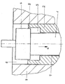
- the sole figure of the drawing shows in a vertical section the essential parts of the injection valve of the invention for a self-ignition reciprocating internal combustion engine.
- nozzle needle with 1 On the drawing are the nozzle needle with 1 and the nozzle needle leading housing labeled 2.
- the housing 2 is seated an outer casing 3.
- the nozzle needle 1 has a round damping collar 4, which in can dip a damping chamber 5.
- the damping chamber 5 is formed by a recess in the housing 2.
- the outer diameter of the nozzle needle 1 and the inner diameter of the housing 2 are dimensioned so that between them Share a free inflow 7 to flow through a Leakage fuel quantity as damping fluid to the damping chamber 5 results. Furthermore, the outer diameter of the Dämpfungsbundes 4 and the inner diameter of the damping chamber 5 so matched that between these two parts when immersing the damping collar in the damping chamber. 5 an annular outflow cross section 8 for the discharge of damping fluid 5 results from the damping chamber.
- the damping collar 4 is arranged on the nozzle needle 1, that the volume of the damping chamber 5 2 to 4 times the volume amounts to the damping collar 4 when immersing displaced into the damping chamber 5. Furthermore, the area is of Abströmqueriteses 8 about 1.5 - 3 times the area of the Inflow cross-section 7.
- the inflow cross section 7 and the outflow cross section 8 form annular.
- these cross sections can also be formed by groove-like depressions in the parts.
Landscapes
- Engineering & Computer Science (AREA)
- Chemical & Material Sciences (AREA)
- Combustion & Propulsion (AREA)
- Mechanical Engineering (AREA)
- General Engineering & Computer Science (AREA)
- Fuel-Injection Apparatus (AREA)
Abstract
Description
Claims (7)
- Einrichtung zum Reduzieren des Nachspritzens eines Einspritzventils mit einer in einem Gehäuse geführten Düsennadel, dadurch gekennzeichnet, dass die Düsennadel (1) mit einem Dämpfungsbund (4) versehen ist und im Gehäuse (2) ein mit Dämpfungsflüssigkeit beaufschlagbarer Dämpfungsraum (5) vorgesehen ist, in den der Dämpfungsbund (4) gegen Ende der Schließbewegung eintaucht.
- Einrichtung nach Anspruch 1, dadurch gekennzeichnet, dass die Dämpfungsflüssigkeit der Kraftstoff einer mit Selbstzündung arbeitenden Hubkolbenbrennkraftmaschine ist.
- Einrichtung nach Anspruch 1 oder 2, dadurch gekennzeichnet, dass zwischen der Düsennadel (1) und dem Gehäuse (2) ein freier Zuströmquerschnitt (7) zum Durchtritt einer Leckkraftstoffmenge zum Dämpfungsraum (5) vorgesehen ist.
- Einrichtung nach einem der vorhergehenden Ansprüche, dadurch gekennzeichnet, dass zwischen dem Dämpfungsbund (4) und der inneren Wandung des Dämpfungsraumes (5) ein freier Abströmquerschnitt (8) zum Austritt von Dämpfungsflüssigkeit vorgesehen ist.
- Einrichtung nach einem der vorhergehenden Ansprüche, dadurch gekennzeichnet, dass der Zu- und der Abströmquerschnitt (7,8) ringförmig ausgebildet sind.
- Einrichtung nach einem der vorhergehenden Ansprüche, dadurch gekennzeichnet, dass der Dämpfungsbund (4) derart an der Düsennadel (1) angeordnet ist, dass das Volumen des Dämpfungsraumes (5) das 2- bis 4-fache des Volumens beträgt, das der Dämpfungsbund (4) gegen Ende der Schließbewegung der Düsennadel (1) verdrängt.
- Einrichtung nach einem der vorhergehenden Ansprüche, dadurch gekennzeichnet, dass die Fläche des Abströmquerschnitts (8) zwischen dem Dämpfungsbund (4) und dem Dämpfungsraum (5) das 1,5 bis 3-fache der Fläche des Zuströmquerschnittes (7) zwischen der Düsennadel (1) und dem Gehäuse(2) beträgt.
Applications Claiming Priority (2)
| Application Number | Priority Date | Filing Date | Title |
|---|---|---|---|
| DE10318255 | 2003-04-23 | ||
| DE10318255A DE10318255A1 (de) | 2003-04-23 | 2003-04-23 | Einrichtung zum Reduzieren des Nachspritzens eines Einspritzventils |
Publications (2)
| Publication Number | Publication Date |
|---|---|
| EP1471249A1 true EP1471249A1 (de) | 2004-10-27 |
| EP1471249B1 EP1471249B1 (de) | 2006-03-01 |
Family
ID=32946398
Family Applications (1)
| Application Number | Title | Priority Date | Filing Date |
|---|---|---|---|
| EP04008827A Expired - Lifetime EP1471249B1 (de) | 2003-04-23 | 2004-04-14 | Einrichtung zum Dämpfen der Schliessbewegung eines Ventilnadels eines Einspritzventils |
Country Status (6)
| Country | Link |
|---|---|
| EP (1) | EP1471249B1 (de) |
| JP (1) | JP4447367B2 (de) |
| KR (1) | KR101274432B1 (de) |
| CN (1) | CN100396908C (de) |
| AT (1) | ATE319004T1 (de) |
| DE (2) | DE10318255A1 (de) |
Cited By (2)
| Publication number | Priority date | Publication date | Assignee | Title |
|---|---|---|---|---|
| US9879645B2 (en) | 2016-02-18 | 2018-01-30 | Caterpillar Inc. | Control valve bounce limiting mechanism for fuel injectors |
| CN114718788A (zh) * | 2021-01-05 | 2022-07-08 | 罗伯特·博世有限公司 | 喷油器以及相应的发动机 |
Families Citing this family (4)
| Publication number | Priority date | Publication date | Assignee | Title |
|---|---|---|---|---|
| JP5019137B2 (ja) | 2009-09-04 | 2012-09-05 | 株式会社デンソー | 電磁駆動弁及びこれを用いた燃料噴射装置 |
| KR101268512B1 (ko) * | 2011-10-26 | 2013-06-04 | 현대중공업 주식회사 | 디젤엔진의 연료분사노즐 |
| CN103321808B (zh) * | 2013-07-08 | 2015-09-16 | 中国第一汽车股份有限公司无锡油泵油嘴研究所 | 一种新型喷油嘴针阀偶件 |
| CN106194537A (zh) * | 2016-07-12 | 2016-12-07 | 江西汇尔油泵油嘴有限公司 | 一种阻尼式喷油方法以及阻尼式喷油嘴 |
Citations (2)
| Publication number | Priority date | Publication date | Assignee | Title |
|---|---|---|---|---|
| DE3246916A1 (de) * | 1982-12-18 | 1984-06-20 | Robert Bosch Gmbh, 7000 Stuttgart | Kraftstoff-einspritzduese fuer brennkraftmaschinen |
| DE3410476A1 (de) * | 1983-08-13 | 1985-02-21 | Robert Bosch Gmbh, 7000 Stuttgart | Kraftstoff-einspritzduese fuer brennkraftmaschinen |
Family Cites Families (4)
| Publication number | Priority date | Publication date | Assignee | Title |
|---|---|---|---|---|
| EP0343147A3 (de) * | 1988-05-16 | 1990-10-03 | Steyr-Daimler-Puch Aktiengesellschaft | Einspritzventil für luftverdichtende Einspritzbrennkraftmaschinen |
| CN2200058Y (zh) * | 1994-01-26 | 1995-06-07 | 天津大学 | 柴油机电控高压喷油器 |
| DE10059425A1 (de) * | 2000-11-30 | 2002-06-06 | Bosch Gmbh Robert | Kraftstoffeinspritzpumpe für Brennkraftmaschinen, insbesondere Dieselmotoren |
| DE10256948A1 (de) * | 2002-12-05 | 2004-06-24 | Robert Bosch Gmbh | Brennstoffeinspritzventil |
-
2003
- 2003-04-23 DE DE10318255A patent/DE10318255A1/de not_active Ceased
-
2004
- 2004-03-24 KR KR1020040019965A patent/KR101274432B1/ko not_active Expired - Fee Related
- 2004-04-14 DE DE502004000312T patent/DE502004000312D1/de not_active Expired - Lifetime
- 2004-04-14 EP EP04008827A patent/EP1471249B1/de not_active Expired - Lifetime
- 2004-04-14 AT AT04008827T patent/ATE319004T1/de not_active IP Right Cessation
- 2004-04-21 JP JP2004125372A patent/JP4447367B2/ja not_active Expired - Fee Related
- 2004-04-23 CN CNB2004100350938A patent/CN100396908C/zh not_active Expired - Fee Related
Patent Citations (2)
| Publication number | Priority date | Publication date | Assignee | Title |
|---|---|---|---|---|
| DE3246916A1 (de) * | 1982-12-18 | 1984-06-20 | Robert Bosch Gmbh, 7000 Stuttgart | Kraftstoff-einspritzduese fuer brennkraftmaschinen |
| DE3410476A1 (de) * | 1983-08-13 | 1985-02-21 | Robert Bosch Gmbh, 7000 Stuttgart | Kraftstoff-einspritzduese fuer brennkraftmaschinen |
Cited By (2)
| Publication number | Priority date | Publication date | Assignee | Title |
|---|---|---|---|---|
| US9879645B2 (en) | 2016-02-18 | 2018-01-30 | Caterpillar Inc. | Control valve bounce limiting mechanism for fuel injectors |
| CN114718788A (zh) * | 2021-01-05 | 2022-07-08 | 罗伯特·博世有限公司 | 喷油器以及相应的发动机 |
Also Published As
| Publication number | Publication date |
|---|---|
| ATE319004T1 (de) | 2006-03-15 |
| CN1550661A (zh) | 2004-12-01 |
| KR20040092398A (ko) | 2004-11-03 |
| DE502004000312D1 (de) | 2006-04-27 |
| CN100396908C (zh) | 2008-06-25 |
| JP2004324645A (ja) | 2004-11-18 |
| JP4447367B2 (ja) | 2010-04-07 |
| DE10318255A1 (de) | 2004-11-25 |
| EP1471249B1 (de) | 2006-03-01 |
| KR101274432B1 (ko) | 2013-06-17 |
Similar Documents
| Publication | Publication Date | Title |
|---|---|---|
| DE19820513A1 (de) | Kraftstoffeinspritzdüse für eine Brennkraftmaschine | |
| DE2419159A1 (de) | Einspritzvorrichtung fuer eine dieselbrennkraftmaschine | |
| DE102007009165A1 (de) | Kraftstoffinjektor mit einer zusätzlichen Ablaufdrossel oder mit einer verbesserten Anordnung derselben im Steuerventil | |
| EP0064146A1 (de) | Einspritzsystem zum Einspritzen zweier Brennstoffe durch eine Einspritzdüse | |
| EP1471249A1 (de) | Einrichtung zum Dämpfen der Schliessbewegung eines Ventilnadels eines Einspritzventils | |
| DE3244290C2 (de) | ||
| DE3113475A1 (de) | "kraftstoffeinspritzduese" | |
| DE19843616A1 (de) | Kraftstoffeinspritzdüse | |
| DE102017218527A1 (de) | Injektor zum Dosieren von flüssigem und gasförmigem Kraftstoff | |
| DE715751C (de) | Brennstoffeinspritzanlage fuer Brennkraftmaschinen | |
| DE19941688C2 (de) | Einspritzeinrichtung für eine Brennkraftmaschine mit Direkteinspritzung | |
| DE4426946B4 (de) | Vorrichtung zum Fördern von Kraftstoff aus einem Vorratsbehälter zur Brennkraftmaschine eines Kraftfahrzeugs | |
| DE19949527A1 (de) | Injektor für ein Kraftstoffeinspritzsystem für Brennkraftmaschinen mit in den Ventilsteuerraum ragender Düsennadel | |
| EP0135872A2 (de) | Kraftstoff-Einspritzdüse für Brennkraftmaschinen | |
| DE10038097A1 (de) | Brennstoffeinspritzventil | |
| DE102007005382A1 (de) | Leckagefreier Injektor | |
| DE102014220345A1 (de) | Kraftstoffeinspritzventil | |
| AT397289B (de) | Kraftstoffeinspritzdüse für brennkraftmaschinen | |
| DE3439672A1 (de) | Elektromagnetisch getaktetes einspritzventil fuer gemischverdichtende brennkraftmaschinen | |
| DE102017212655A1 (de) | Injektor für flüssigen und gasförmigen Kraftstoff | |
| DE3112100A1 (de) | "druckventil fuer eine brennstoffeinspritzpumpe" | |
| DE2726300A1 (de) | Kraftstoffeinspritzduese | |
| DE968899C (de) | Vorrichtung bei Dieselmotoren zur kontinuierlichen Einspritzung von Brennstoff in zwei zusammenhaengenden Phasen | |
| CH629872A5 (en) | Device for the injection of fuel in an air-compressing internal combustion engine | |
| DE19930832A1 (de) | Kraftstoffeinspritzventil |
Legal Events
| Date | Code | Title | Description |
|---|---|---|---|
| PUAI | Public reference made under article 153(3) epc to a published international application that has entered the european phase |
Free format text: ORIGINAL CODE: 0009012 |
|
| AK | Designated contracting states |
Kind code of ref document: A1 Designated state(s): AT BE BG CH CY CZ DE DK EE ES FI FR GB GR HU IE IT LI LU MC NL PL PT RO SE SI SK TR |
|
| AX | Request for extension of the european patent |
Extension state: AL HR LT LV MK |
|
| 17P | Request for examination filed |
Effective date: 20041110 |
|
| 17Q | First examination report despatched |
Effective date: 20041203 |
|
| AKX | Designation fees paid |
Designated state(s): AT BE BG CH CY CZ DE DK EE ES FI FR GB GR HU IE IT LI LU MC NL PL PT RO SE SI SK TR |
|
| GRAP | Despatch of communication of intention to grant a patent |
Free format text: ORIGINAL CODE: EPIDOSNIGR1 |
|
| GRAS | Grant fee paid |
Free format text: ORIGINAL CODE: EPIDOSNIGR3 |
|
| GRAA | (expected) grant |
Free format text: ORIGINAL CODE: 0009210 |
|
| AK | Designated contracting states |
Kind code of ref document: B1 Designated state(s): AT BE BG CH CY CZ DE DK EE ES FI FR GB GR HU IE IT LI LU MC NL PL PT RO SE SI SK TR |
|
| PG25 | Lapsed in a contracting state [announced via postgrant information from national office to epo] |
Ref country code: PL Free format text: LAPSE BECAUSE OF FAILURE TO SUBMIT A TRANSLATION OF THE DESCRIPTION OR TO PAY THE FEE WITHIN THE PRESCRIBED TIME-LIMIT Effective date: 20060301 Ref country code: IE Free format text: LAPSE BECAUSE OF FAILURE TO SUBMIT A TRANSLATION OF THE DESCRIPTION OR TO PAY THE FEE WITHIN THE PRESCRIBED TIME-LIMIT Effective date: 20060301 Ref country code: SI Free format text: LAPSE BECAUSE OF FAILURE TO SUBMIT A TRANSLATION OF THE DESCRIPTION OR TO PAY THE FEE WITHIN THE PRESCRIBED TIME-LIMIT Effective date: 20060301 Ref country code: SK Free format text: LAPSE BECAUSE OF FAILURE TO SUBMIT A TRANSLATION OF THE DESCRIPTION OR TO PAY THE FEE WITHIN THE PRESCRIBED TIME-LIMIT Effective date: 20060301 Ref country code: RO Free format text: LAPSE BECAUSE OF FAILURE TO SUBMIT A TRANSLATION OF THE DESCRIPTION OR TO PAY THE FEE WITHIN THE PRESCRIBED TIME-LIMIT Effective date: 20060301 |
|
| REG | Reference to a national code |
Ref country code: GB Ref legal event code: FG4D Free format text: NOT ENGLISH |
|
| REG | Reference to a national code |
Ref country code: CH Ref legal event code: EP Ref country code: CH Ref legal event code: NV Representative=s name: E. BLUM & CO. PATENTANWAELTE |
|
| REG | Reference to a national code |
Ref country code: IE Ref legal event code: FG4D Free format text: LANGUAGE OF EP DOCUMENT: GERMAN |
|
| GBT | Gb: translation of ep patent filed (gb section 77(6)(a)/1977) |
Effective date: 20060316 |
|
| PG25 | Lapsed in a contracting state [announced via postgrant information from national office to epo] |
Ref country code: AT Free format text: LAPSE BECAUSE OF NON-PAYMENT OF DUE FEES Effective date: 20060414 |
|
| REF | Corresponds to: |
Ref document number: 502004000312 Country of ref document: DE Date of ref document: 20060427 Kind code of ref document: P |
|
| PG25 | Lapsed in a contracting state [announced via postgrant information from national office to epo] |
Ref country code: BE Free format text: LAPSE BECAUSE OF NON-PAYMENT OF DUE FEES Effective date: 20060430 Ref country code: MC Free format text: LAPSE BECAUSE OF NON-PAYMENT OF DUE FEES Effective date: 20060430 |
|
| PG25 | Lapsed in a contracting state [announced via postgrant information from national office to epo] |
Ref country code: SE Free format text: LAPSE BECAUSE OF FAILURE TO SUBMIT A TRANSLATION OF THE DESCRIPTION OR TO PAY THE FEE WITHIN THE PRESCRIBED TIME-LIMIT Effective date: 20060601 Ref country code: BG Free format text: LAPSE BECAUSE OF FAILURE TO SUBMIT A TRANSLATION OF THE DESCRIPTION OR TO PAY THE FEE WITHIN THE PRESCRIBED TIME-LIMIT Effective date: 20060601 Ref country code: DK Free format text: LAPSE BECAUSE OF FAILURE TO SUBMIT A TRANSLATION OF THE DESCRIPTION OR TO PAY THE FEE WITHIN THE PRESCRIBED TIME-LIMIT Effective date: 20060601 |
|
| PG25 | Lapsed in a contracting state [announced via postgrant information from national office to epo] |
Ref country code: ES Free format text: LAPSE BECAUSE OF FAILURE TO SUBMIT A TRANSLATION OF THE DESCRIPTION OR TO PAY THE FEE WITHIN THE PRESCRIBED TIME-LIMIT Effective date: 20060612 |
|
| PG25 | Lapsed in a contracting state [announced via postgrant information from national office to epo] |
Ref country code: PT Free format text: LAPSE BECAUSE OF FAILURE TO SUBMIT A TRANSLATION OF THE DESCRIPTION OR TO PAY THE FEE WITHIN THE PRESCRIBED TIME-LIMIT Effective date: 20060801 |
|
| ET | Fr: translation filed | ||
| REG | Reference to a national code |
Ref country code: IE Ref legal event code: FD4D |
|
| PLBE | No opposition filed within time limit |
Free format text: ORIGINAL CODE: 0009261 |
|
| STAA | Information on the status of an ep patent application or granted ep patent |
Free format text: STATUS: NO OPPOSITION FILED WITHIN TIME LIMIT |
|
| 26N | No opposition filed |
Effective date: 20061204 |
|
| REG | Reference to a national code |
Ref country code: CH Ref legal event code: PFA Owner name: MAN B&W DIESEL AG Free format text: MAN B&W DIESEL AG# #86224 AUGSBURG (DE) -TRANSFER TO- MAN B&W DIESEL AG# #86224 AUGSBURG (DE) |
|
| BERE | Be: lapsed |
Owner name: MAN B&W DIESEL A.G. Effective date: 20060430 |
|
| PG25 | Lapsed in a contracting state [announced via postgrant information from national office to epo] |
Ref country code: GR Free format text: LAPSE BECAUSE OF FAILURE TO SUBMIT A TRANSLATION OF THE DESCRIPTION OR TO PAY THE FEE WITHIN THE PRESCRIBED TIME-LIMIT Effective date: 20060602 Ref country code: CZ Free format text: LAPSE BECAUSE OF FAILURE TO SUBMIT A TRANSLATION OF THE DESCRIPTION OR TO PAY THE FEE WITHIN THE PRESCRIBED TIME-LIMIT Effective date: 20060301 |
|
| PG25 | Lapsed in a contracting state [announced via postgrant information from national office to epo] |
Ref country code: EE Free format text: LAPSE BECAUSE OF FAILURE TO SUBMIT A TRANSLATION OF THE DESCRIPTION OR TO PAY THE FEE WITHIN THE PRESCRIBED TIME-LIMIT Effective date: 20060301 |
|
| PG25 | Lapsed in a contracting state [announced via postgrant information from national office to epo] |
Ref country code: LU Free format text: LAPSE BECAUSE OF NON-PAYMENT OF DUE FEES Effective date: 20060414 Ref country code: TR Free format text: LAPSE BECAUSE OF FAILURE TO SUBMIT A TRANSLATION OF THE DESCRIPTION OR TO PAY THE FEE WITHIN THE PRESCRIBED TIME-LIMIT Effective date: 20060301 Ref country code: HU Free format text: LAPSE BECAUSE OF FAILURE TO SUBMIT A TRANSLATION OF THE DESCRIPTION OR TO PAY THE FEE WITHIN THE PRESCRIBED TIME-LIMIT Effective date: 20060902 |
|
| PG25 | Lapsed in a contracting state [announced via postgrant information from national office to epo] |
Ref country code: CY Free format text: LAPSE BECAUSE OF FAILURE TO SUBMIT A TRANSLATION OF THE DESCRIPTION OR TO PAY THE FEE WITHIN THE PRESCRIBED TIME-LIMIT Effective date: 20060301 |
|
| REG | Reference to a national code |
Ref country code: CH Ref legal event code: PFA Owner name: AN DIESEL & TURBO SE Free format text: MAN B&W DIESEL AG# #86224 AUGSBURG (DE) -TRANSFER TO- MAN DIESEL & TURBO SE#STADTBACHSTRASSE 1#86153 AUGSBURG (DE) |
|
| REG | Reference to a national code |
Ref country code: FR Ref legal event code: PLFP Year of fee payment: 13 |
|
| REG | Reference to a national code |
Ref country code: FR Ref legal event code: PLFP Year of fee payment: 14 |
|
| REG | Reference to a national code |
Ref country code: FR Ref legal event code: PLFP Year of fee payment: 15 |
|
| REG | Reference to a national code |
Ref country code: CH Ref legal event code: PFA Owner name: MAN ENERGY SOLUTIONS SE, DE Free format text: FORMER OWNER: MAN DIESEL AND TURBO SE, DE |
|
| REG | Reference to a national code |
Ref country code: DE Ref legal event code: R081 Ref document number: 502004000312 Country of ref document: DE Owner name: MAN ENERGY SOLUTIONS SE, DE Free format text: FORMER OWNER: MAN DIESEL & TURBO SE, 86153 AUGSBURG, DE |
|
| REG | Reference to a national code |
Ref country code: NL Ref legal event code: HC Owner name: MAN ENERGY SOLUTIONS SE; DE Free format text: DETAILS ASSIGNMENT: CHANGE OF OWNER(S), CHANGE OF OWNER(S) NAME; FORMER OWNER NAME: MAN B&W DIESEL AG Effective date: 20181221 |
|
| REG | Reference to a national code |
Ref country code: GB Ref legal event code: 732E Free format text: REGISTERED BETWEEN 20190404 AND 20190410 |
|
| PGFP | Annual fee paid to national office [announced via postgrant information from national office to epo] |
Ref country code: NL Payment date: 20190418 Year of fee payment: 16 |
|
| PGFP | Annual fee paid to national office [announced via postgrant information from national office to epo] |
Ref country code: FI Payment date: 20190424 Year of fee payment: 16 Ref country code: IT Payment date: 20190429 Year of fee payment: 16 Ref country code: DE Payment date: 20190418 Year of fee payment: 16 |
|
| PGFP | Annual fee paid to national office [announced via postgrant information from national office to epo] |
Ref country code: FR Payment date: 20190418 Year of fee payment: 16 |
|
| PGFP | Annual fee paid to national office [announced via postgrant information from national office to epo] |
Ref country code: CH Payment date: 20190418 Year of fee payment: 16 |
|
| PGFP | Annual fee paid to national office [announced via postgrant information from national office to epo] |
Ref country code: GB Payment date: 20190418 Year of fee payment: 16 |
|
| REG | Reference to a national code |
Ref country code: DE Ref legal event code: R119 Ref document number: 502004000312 Country of ref document: DE |
|
| REG | Reference to a national code |
Ref country code: FI Ref legal event code: MAE |
|
| REG | Reference to a national code |
Ref country code: CH Ref legal event code: PL |
|
| REG | Reference to a national code |
Ref country code: NL Ref legal event code: MM Effective date: 20200501 |
|
| PG25 | Lapsed in a contracting state [announced via postgrant information from national office to epo] |
Ref country code: CH Free format text: LAPSE BECAUSE OF NON-PAYMENT OF DUE FEES Effective date: 20200430 Ref country code: FI Free format text: LAPSE BECAUSE OF NON-PAYMENT OF DUE FEES Effective date: 20200414 Ref country code: LI Free format text: LAPSE BECAUSE OF NON-PAYMENT OF DUE FEES Effective date: 20200430 Ref country code: FR Free format text: LAPSE BECAUSE OF NON-PAYMENT OF DUE FEES Effective date: 20200430 Ref country code: DE Free format text: LAPSE BECAUSE OF NON-PAYMENT OF DUE FEES Effective date: 20201103 |
|
| GBPC | Gb: european patent ceased through non-payment of renewal fee |
Effective date: 20200414 |
|
| PG25 | Lapsed in a contracting state [announced via postgrant information from national office to epo] |
Ref country code: NL Free format text: LAPSE BECAUSE OF NON-PAYMENT OF DUE FEES Effective date: 20200501 |
|
| PG25 | Lapsed in a contracting state [announced via postgrant information from national office to epo] |
Ref country code: GB Free format text: LAPSE BECAUSE OF NON-PAYMENT OF DUE FEES Effective date: 20200414 |
|
| PG25 | Lapsed in a contracting state [announced via postgrant information from national office to epo] |
Ref country code: IT Free format text: LAPSE BECAUSE OF NON-PAYMENT OF DUE FEES Effective date: 20200414 |