EP1470879A1 - Surface coated cutting tool member having hard coating layer exhibiting excellent abrasion resistance in high-speed cutting, and method for forming said hard coating layer on surface of cutting tool - Google Patents
Surface coated cutting tool member having hard coating layer exhibiting excellent abrasion resistance in high-speed cutting, and method for forming said hard coating layer on surface of cutting tool Download PDFInfo
- Publication number
- EP1470879A1 EP1470879A1 EP03701078A EP03701078A EP1470879A1 EP 1470879 A1 EP1470879 A1 EP 1470879A1 EP 03701078 A EP03701078 A EP 03701078A EP 03701078 A EP03701078 A EP 03701078A EP 1470879 A1 EP1470879 A1 EP 1470879A1
- Authority
- EP
- European Patent Office
- Prior art keywords
- containing points
- aluminum containing
- minimum
- coating layer
- maximum
- Prior art date
- Legal status (The legal status is an assumption and is not a legal conclusion. Google has not performed a legal analysis and makes no representation as to the accuracy of the status listed.)
- Granted
Links
Images


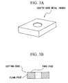

Classifications
-
- B—PERFORMING OPERATIONS; TRANSPORTING
- B23—MACHINE TOOLS; METAL-WORKING NOT OTHERWISE PROVIDED FOR
- B23B—TURNING; BORING
- B23B27/00—Tools for turning or boring machines; Tools of a similar kind in general; Accessories therefor
- B23B27/14—Cutting tools of which the bits or tips or cutting inserts are of special material
-
- C—CHEMISTRY; METALLURGY
- C23—COATING METALLIC MATERIAL; COATING MATERIAL WITH METALLIC MATERIAL; CHEMICAL SURFACE TREATMENT; DIFFUSION TREATMENT OF METALLIC MATERIAL; COATING BY VACUUM EVAPORATION, BY SPUTTERING, BY ION IMPLANTATION OR BY CHEMICAL VAPOUR DEPOSITION, IN GENERAL; INHIBITING CORROSION OF METALLIC MATERIAL OR INCRUSTATION IN GENERAL
- C23C—COATING METALLIC MATERIAL; COATING MATERIAL WITH METALLIC MATERIAL; SURFACE TREATMENT OF METALLIC MATERIAL BY DIFFUSION INTO THE SURFACE, BY CHEMICAL CONVERSION OR SUBSTITUTION; COATING BY VACUUM EVAPORATION, BY SPUTTERING, BY ION IMPLANTATION OR BY CHEMICAL VAPOUR DEPOSITION, IN GENERAL
- C23C30/00—Coating with metallic material characterised only by the composition of the metallic material, i.e. not characterised by the coating process
- C23C30/005—Coating with metallic material characterised only by the composition of the metallic material, i.e. not characterised by the coating process on hard metal substrates
-
- C—CHEMISTRY; METALLURGY
- C23—COATING METALLIC MATERIAL; COATING MATERIAL WITH METALLIC MATERIAL; CHEMICAL SURFACE TREATMENT; DIFFUSION TREATMENT OF METALLIC MATERIAL; COATING BY VACUUM EVAPORATION, BY SPUTTERING, BY ION IMPLANTATION OR BY CHEMICAL VAPOUR DEPOSITION, IN GENERAL; INHIBITING CORROSION OF METALLIC MATERIAL OR INCRUSTATION IN GENERAL
- C23C—COATING METALLIC MATERIAL; COATING MATERIAL WITH METALLIC MATERIAL; SURFACE TREATMENT OF METALLIC MATERIAL BY DIFFUSION INTO THE SURFACE, BY CHEMICAL CONVERSION OR SUBSTITUTION; COATING BY VACUUM EVAPORATION, BY SPUTTERING, BY ION IMPLANTATION OR BY CHEMICAL VAPOUR DEPOSITION, IN GENERAL
- C23C14/00—Coating by vacuum evaporation, by sputtering or by ion implantation of the coating forming material
- C23C14/06—Coating by vacuum evaporation, by sputtering or by ion implantation of the coating forming material characterised by the coating material
-
- C—CHEMISTRY; METALLURGY
- C23—COATING METALLIC MATERIAL; COATING MATERIAL WITH METALLIC MATERIAL; CHEMICAL SURFACE TREATMENT; DIFFUSION TREATMENT OF METALLIC MATERIAL; COATING BY VACUUM EVAPORATION, BY SPUTTERING, BY ION IMPLANTATION OR BY CHEMICAL VAPOUR DEPOSITION, IN GENERAL; INHIBITING CORROSION OF METALLIC MATERIAL OR INCRUSTATION IN GENERAL
- C23C—COATING METALLIC MATERIAL; COATING MATERIAL WITH METALLIC MATERIAL; SURFACE TREATMENT OF METALLIC MATERIAL BY DIFFUSION INTO THE SURFACE, BY CHEMICAL CONVERSION OR SUBSTITUTION; COATING BY VACUUM EVAPORATION, BY SPUTTERING, BY ION IMPLANTATION OR BY CHEMICAL VAPOUR DEPOSITION, IN GENERAL
- C23C14/00—Coating by vacuum evaporation, by sputtering or by ion implantation of the coating forming material
- C23C14/06—Coating by vacuum evaporation, by sputtering or by ion implantation of the coating forming material characterised by the coating material
- C23C14/0641—Nitrides
-
- Y—GENERAL TAGGING OF NEW TECHNOLOGICAL DEVELOPMENTS; GENERAL TAGGING OF CROSS-SECTIONAL TECHNOLOGIES SPANNING OVER SEVERAL SECTIONS OF THE IPC; TECHNICAL SUBJECTS COVERED BY FORMER USPC CROSS-REFERENCE ART COLLECTIONS [XRACs] AND DIGESTS
- Y10—TECHNICAL SUBJECTS COVERED BY FORMER USPC
- Y10T—TECHNICAL SUBJECTS COVERED BY FORMER US CLASSIFICATION
- Y10T428/00—Stock material or miscellaneous articles
- Y10T428/24—Structurally defined web or sheet [e.g., overall dimension, etc.]
- Y10T428/24942—Structurally defined web or sheet [e.g., overall dimension, etc.] including components having same physical characteristic in differing degree
-
- Y—GENERAL TAGGING OF NEW TECHNOLOGICAL DEVELOPMENTS; GENERAL TAGGING OF CROSS-SECTIONAL TECHNOLOGIES SPANNING OVER SEVERAL SECTIONS OF THE IPC; TECHNICAL SUBJECTS COVERED BY FORMER USPC CROSS-REFERENCE ART COLLECTIONS [XRACs] AND DIGESTS
- Y10—TECHNICAL SUBJECTS COVERED BY FORMER USPC
- Y10T—TECHNICAL SUBJECTS COVERED BY FORMER US CLASSIFICATION
- Y10T428/00—Stock material or miscellaneous articles
- Y10T428/24—Structurally defined web or sheet [e.g., overall dimension, etc.]
- Y10T428/24942—Structurally defined web or sheet [e.g., overall dimension, etc.] including components having same physical characteristic in differing degree
- Y10T428/2495—Thickness [relative or absolute]
- Y10T428/24967—Absolute thicknesses specified
- Y10T428/24975—No layer or component greater than 5 mils thick
-
- Y—GENERAL TAGGING OF NEW TECHNOLOGICAL DEVELOPMENTS; GENERAL TAGGING OF CROSS-SECTIONAL TECHNOLOGIES SPANNING OVER SEVERAL SECTIONS OF THE IPC; TECHNICAL SUBJECTS COVERED BY FORMER USPC CROSS-REFERENCE ART COLLECTIONS [XRACs] AND DIGESTS
- Y10—TECHNICAL SUBJECTS COVERED BY FORMER USPC
- Y10T—TECHNICAL SUBJECTS COVERED BY FORMER US CLASSIFICATION
- Y10T428/00—Stock material or miscellaneous articles
- Y10T428/26—Web or sheet containing structurally defined element or component, the element or component having a specified physical dimension
- Y10T428/263—Coating layer not in excess of 5 mils thick or equivalent
- Y10T428/264—Up to 3 mils
- Y10T428/265—1 mil or less
Definitions
- the present invention relates to a surface-coated cutting tool member (hereinafter referred to as a coated cutting tool) having a hard coating layer exhibiting superior high temperature properties, and thereby exhibiting a superior wear resistance during a high speed cutting operation for various kinds of steels and cast irons in which a significant amount of heat is generated.
- a coated cutting tool having a hard coating layer exhibiting superior high temperature properties, and thereby exhibiting a superior wear resistance during a high speed cutting operation for various kinds of steels and cast irons in which a significant amount of heat is generated.
- the present invention relates to a method for forming the above-mentioned hard coating layer on a surface of a cutting tool.
- cutting tools include an indexable insert which is detachably attached to a tip portion of a cutting tool in order to perform a turning or planing operation for a workpiece such as made of various steels or cast irons, a drill or a miniature drill which is used for performing a drilling operation for a workpiece as mentioned above, and a solid type end mill which is used for performing a face milling operation, a groove milling operation, or a shoulder milling operation for a workpiece as mentioned above.
- an indexable type end mill is also known, to which an indexable insert is detachably attached for performing a cutting operation as in the case of the solid type end mill.
- a method in which a cutting tool made of a tungsten carbide (hereinafter termed WC) based cemented carbide, a titanium carbonitride (hereinafter termed TiCN) based cermet, or a cubic boron nitride (hereinafter termed c-BN) based sintered material, is accommodated in, for example, an arc ion plating apparatus schematically shown in FIG.
- WC tungsten carbide
- TiCN titanium carbonitride
- c-BN cubic boron nitride
- an electric current of, for example, 90A is made to flow as an arc discharge between an anode electrode and a cathode electrode (an evaporation source) to which an Al-Ti alloy having a predetermined composition is attached under the conditions in which the inside of the apparatus is heated to a temperature of, for example, 500°C using a heater, a nitrogen gas as a reaction gas is introduced into the apparatus so as to prepare a reaction atmosphere at, for example, 2 Pa, and a bias voltage of -100 V is applied to the cutting tool, so that a hard coating layer, which has an average thickness of 1 to 15 ⁇ m and is made of a nitride compound (hereinafter termed (Al, Ti)N) layer that includes aluminum and titanium and satisfies a composition formula of (Al Z Ti 1-Z )N (where Z indicates an atomic ratio of 0.4 to 0.65), is formed on the surface of the cutting tool.
- a hard coating layer which has an average thickness of 1 to 15 ⁇ m and is made of
- cutting operation apparatuses tend to have significantly high performance, and on the other hand, it is strongly demanded that cutting operations be performed with less power, less energy, and less cost; therefore, cutting operations tend to be performed at high speed.
- conventional cutting tool no significant problem is encountered when such a tool is used under normal cutting conditions; however, when such a tool is used under high speed cutting conditions in which a significant amount of heat is generated, wear of the hard coating layer of the tool is significantly progressed, which leads to a relatively short operation life.
- the present invention was conceived in view of the aforementioned research results, and provides a surface-coated cutting tool member whose hard coating layer exhibiting a superior wear resistance during a high speed cutting operation, the surface-coated cutting tool member including: a cutting tool substrate; and a hard coating layer of an (AI, Ti)N, which is formed on a surface of the substrate using a physical vapor deposition method at an overall average thickness of 1 to 15 ⁇ m, wherein the hard coating layer has a component concentration profile in which maximum aluminum containing points (minimum titanium containing points) and minimum aluminum containing points (maximum titanium containing points) appear altematingly and repeatedly at a predetermined interval in a direction of thickness of the hard coating layer, and the amount of contained aluminum (or titanium) is continuously changed from the maximum aluminum containing points to the minimum aluminum containing points and from the minimum aluminum containing points to the maximum aluminum containing points, the maximum aluminum containing points satisfy a composition formula of (Al X Ti 1-X )N (where X indicates an atomic ratio of
- the present invention also provides a method for forming a hard coating layer exhibiting a superior wear resistance during a high speed cutting operation on a surface of a cutting tool.
- the method includes: mounting the cutting tool of a WC based cemented carbide and/or a TiCN based cermet and/or a c-BN based sintered material on a turntable housed in an arc ion plating apparatus at a position radially away from a center axis of the turntable in a manner rotatable about an axis of the cutting tool; producing a nitrogen gas atmosphere as the reaction atmosphere in the arc ion plating apparatus; and generating arc discharge between a cathode electrode of an Al-Ti alloy for forming maximum aluminum containing points (minimum titanium containing points) and an anode electrode, and between another cathode electrode of a Ti-Al alloy for forming minimum aluminum containing points (maximum titanium containing points), which is disposed so as to oppose to the catho
- Aluminum is included in the (Al, Ti)N layer of the hard coating layer in order to improve high temperature hardness and heat resistance (i.e., high temperature properties) of the TiN layer having high toughness; therefore, when the ratio (atomic ratio: X) of aluminum with respect to a total amount of aluminum and titanium is less than 0.70, desired superior high temperature properties cannot be obtained, and on the other hand, when the ratio is greater than 0.95, toughness is significantly reduced due to low ratio of titanium, and a cutting edge tends to easily be chipped (small fracturing). Accordingly, the ratio was set from 0.70 to 0.95.
- the maximum aluminum containing points exhibit superior high temperature properties; however, in contrast, exhibit inferior toughness; therefore, in order to improve toughness of the maximum aluminum containing points, the minimum aluminum containing points, which include titanium at a high ratio and exhibit high toughness, are alternatingly interposed in the thickness direction.
- the ratio (atomic ratio: Y) of titanium with respect to a total amount of aluminum and titanium is greater than 0.65, a desired superior toughness cannot be obtained, and on the other hand, when the ratio is less than 0.40, the minimum aluminum containing points cannot have desired superior high temperature properties because a relative ratio of titanium is too high. Accordingly, the ratio was set from 0.40 to 0.65.
- the distance between the maximum aluminum containing point and the minimum aluminum containing point was set from 0.01 to 0.1 ⁇ m because when the distance is less than 0.01 ⁇ m, it is difficult to form each of the points so as to have the aforementioned composition, and when the distance is greater than 0.1 ⁇ m, weaknesses at each of the points, i.e., insufficient toughness in the case of the maximum aluminum containing point, and insufficient high temperature properties in the case of the minimum aluminum containing point, will locally appear in the layer, which may lead to chipping in the cutting edge or excessive wear.
- the average thickness was set from 1 to 15 ⁇ m because when the thickness of the layer is less than 1 ⁇ m, a desired wear resistance cannot be ensured, and in contrast, when the average thickness is greater than 15 ⁇ m, the cutting edge tends to be chipped.
- ingredient powders i.e., powders of WC, TiC, ZrC, VC, TaC, NbC, Cr 3 C 2 , TiN, TaN, and Co, all of which have an average grain size in a range from 1 to 3 ⁇ m, were prepared and mixed in accordance with blending ratios shown in TABLE 1.
- the ingredient powders were mixed under wet conditions using a ball mill for 72 hours, were dried, and were compacted under pressure of 100 MPa so as to form green compacts.
- the green compacts were held in a vacuum of 6Pa at a temperature of 1400°C for 1 hour so as to be sintered.
- a honing process in which a radius is set to be 0.03, is applied to cutting edge portions of each of the sintered compacts so as to obtain hard metal substrates A-1 to A-10 of WC based hard metal, each of which had an insert shape defined as CNMG120408 in the ISO standard.
- the ingredient powders were mixed under wet conditions using a ball mill for 24 hours, were dried, and were compacted under pressure of 100 MPa so as to form green compacts.
- the green compacts for forming hard metal substrates B-1 to B-6 were held in a nitrogen atmosphere of 2 kPa, and at a temperature of 1500°C for 1 hour, and were cooled in an oven so as to be sintered.
- the green compacts for forming hard metal substrates B-7 to B-9 were held in a vacuum of 1 Pa while increasing temperature from room temperature to 1300°C, in a nitrogen atmosphere of 1 kPa while increasing temperature from 1300°C to 1350°C, in a vacuum of 1 Pa while increasing temperature from 1350°C to 1400°C, in a nitrogen atmosphere of 2 kPa while increasing temperature from 1400°C to 1450°C, and in a vacuum of 1 Pa while increasing temperature from 1450°C to 1500°C.
- the green compacts were held in a nitrogen atmosphere of 3 kPa for 1 hour, and were cooled in the oven so as to be sintered.
- a honing process in which a radius is set to be 0.03, is applied to cutting edge portions of each of the sintered compacts so as to obtain hard metal substrates B-1 to B-9 of TiCN cermet, each of which had an insert shape defined as CNMG120408 in the ISO standard.
- each of the hard metal substrates B-1 to B-9 was observed using a scanning electron microscope.
- the hard metal substrates B-1 to B-6 exhibited a two-phase structure including a hard phase, which is uniform from the surface to the interior, and which made of carbonitride compounds including titanium and at least one of Zr, Ta, Nb, Mo, and W, and a bonded phase having Co and Ni as primary components.
- the hard metal substrates B-7 to B-9 exhibited the same structure as the aforementioned two-phase structure in the interior; however, a surface layer in which the bonded phase did not exist over a depth of 1 to 3 ⁇ m from the surface, i.e., a surface layer consisting of the carbonitride compound, was observed in a superficial portion.
- the aforementioned hard metal substrates A-1 to A-10 and B-1 to B-9 were subjected to ultrasonic cleaning in an acetone solvent, were dried, and were mounted on a turntable housed in an arc ion plating apparatus shown in FIGS. 1A and 1B at positions radially away from a center axis of the turntable in a manner rotatable about respective axes of the hard metal substrates.
- a Ti-Al alloy having various components for forming minimum aluminum containing points was set as a cathode electrode (evaporation source)
- an Al-Ti alloy having various components for forming maximum aluminum containing points was set as another cathode electrode (evaporation source) so as to oppose to the cathode electrode of a Ti-Al alloy while having the turntable therebetween, and metallic titanium for bombardment cleaning is also set.
- the inside of the apparatus was evacuated and maintained at a vacuum at a pressure of 0.5 Pa or less, and the inside of the apparatus was heated to a temperature of 500°C using a heater.
- a DC bias voltage of -1000 V was applied to the hard metal substrates which are turned while rotating on the turntable about the respective axes thereof, and an electric current of 100A was made flow as an arc discharge between the cathode electrode, i.e., metallic titanium, and an anode electrode, so that the surfaces of the hard metal substrates were subjected to Ti bombardment cleaning.
- a nitrogen gas as a reaction gas, was introduced into the apparatus so as to prepare a reaction atmosphere at a pressure of 2 Pa, a DC bias voltage of -100 V was applied to the hard metal substrates which are turned while rotating on the turntable about the respective axes thereof, and an electric current of 100A was made to flow as an arc discharge between the cathode electrodes (the Ti-Al alloy for forming the minimum aluminum containing points and the Al-Ti alloy for forming the maximum aluminum containing points) and the anode electrodes, respectively, so that the method of the present invention was carried out by which a hard coating layer, which had component concentration profile in which the minimum aluminum containing points and the maximum aluminum containing points having a designated composition shown in TABLES 3 and 4 appear alternatingly and repeatedly at a designated interval also shown in TABLES 3 and 4 in the thickness direction, and the amount of contained aluminum (or titanium) is continuously changed from the maximum aluminum containing points to the minimum aluminum containing points and from the minimum aluminum containing points to the maximum aluminum containing points
- the hard metal substrates A-1 to A-10 and B-1 to B-9 were subjected to ultrasonic cleaning in acetone, were dried, and were accommodated in a conventional arc ion plating apparatus shown in FIG 2.
- an Al-Ti alloy having various components was set as a cathode electrode (evaporation source), the inside of the apparatus was evacuated and maintained at a vacuum at a pressure of 0.5 Pa or less, the inside of the apparatus was heated to a temperature of 500°C using a heater, and an argon gas was introduced into the apparatus so as to prepare an argon atmosphere at a pressure of 10 Pa.
- a bias voltage of -800 V was applied to the hard metal substrates so that the surfaces of the hard metal substrates were subjected to argon gas bombardment cleaning.
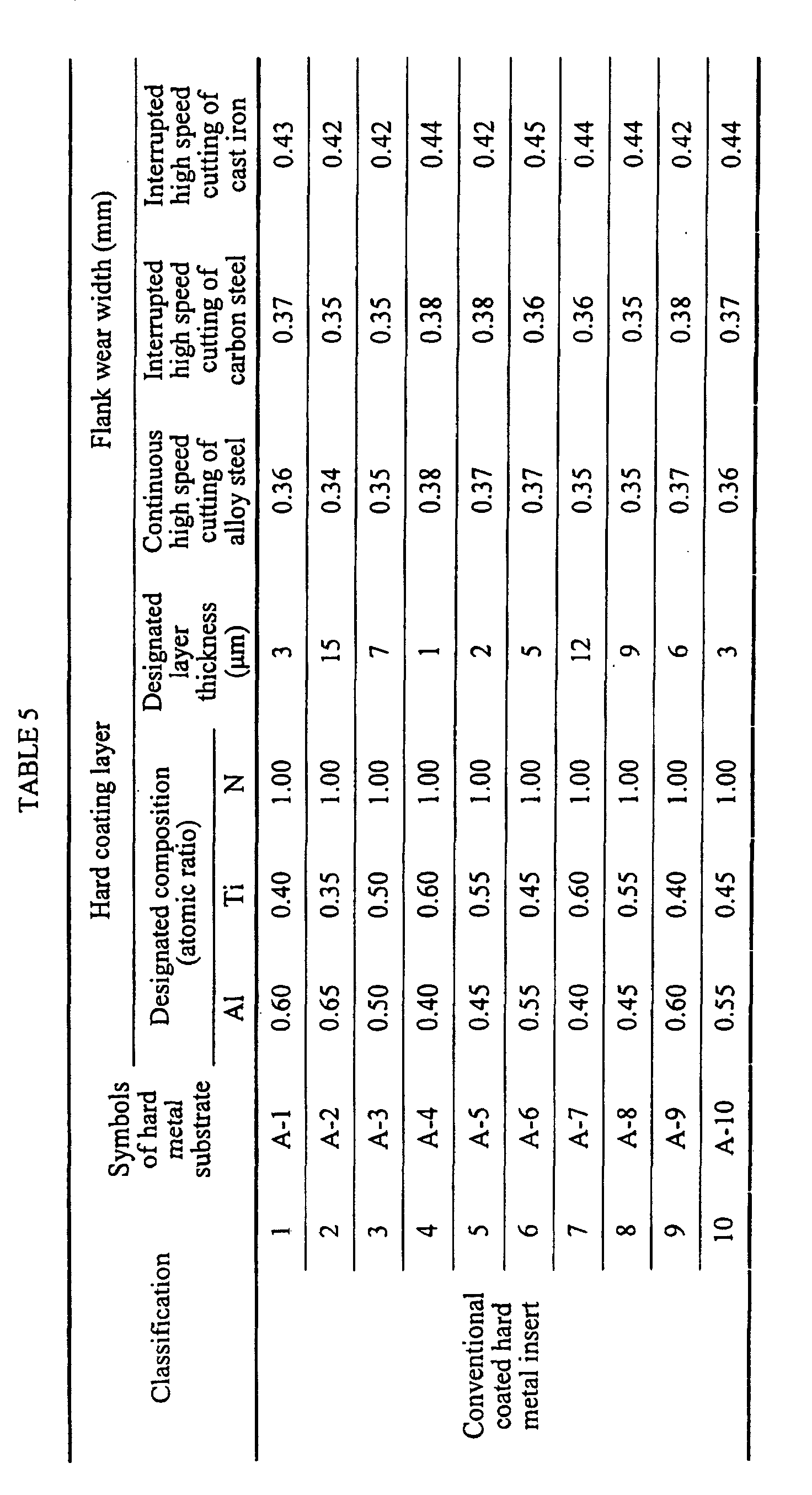
- a nitrogen gas, as a reaction gas was introduced into the apparatus so as to prepare a reaction atmosphere at a pressure of 2 Pa, the bias voltage applied to the hard metal substrates was decreased to -100 V, and an electric current was made to flow as an arc discharge between the cathode electrode and the anode electrode so that a conventional method was carried out by which a hard coating layer, which had a designated composition and a designated layer thickness shown in TABLES 5 and 6, and which included an (Al, Ti)N layer in which composition was substantially constant in the direction of the layer thickness, was formed, by a vapor deposition method, on the surface of each of the hard metal substrates A-1 to A-10 and B-1 to B-9, and thereby conventional surface-coated hard metal indexable inserts 1 to 19 (hereinafter referred to as conventional coated hard metal inserts) also having a
- coated hard metal inserts 1 to 19 of the present invention and the conventional coated hard metal inserts 1 to 19 were subjected to cutting tests by attaching each of them to a tip portion of a cutting tool made of tool steel using a fixing bridge and a screw.
- the detailed test conditions were set as follows:
- ingredient powders i.e., medium coarse powder of WC having an average grain size of 5.5 ⁇ m, fine powder of WC having an average grain size of 0.8 ⁇ m, powder of TaC having an average grain size of 1.3 ⁇ m, powder of NbC having an average grain size of 1.2 ⁇ m, powder of ZrC having an average grain size of 1.2 ⁇ m, powder of Cr 3 C 2 having an average grain size of 2.3 ⁇ m, powder of VC having an average grain size of 1.5 ⁇ m, powder of (Ti, W)C having an average grain size of 1.0 ⁇ m, and powder of Co having an average grain size of 1.8 ⁇ m, were prepared.
- medium coarse powder of WC having an average grain size of 5.5 ⁇ m
- fine powder of WC having an average grain size of 0.8 ⁇ m
- powder of TaC having an average grain size of 1.3 ⁇ m
- powder of NbC having an average grain size of 1.2 ⁇ m
- powder of ZrC having an average grain size of 1.2
- the ingredient powders were blended according to the blending ratios shown in TABLE 7, were mixed in acetone after adding wax for 24 hours using a ball mill, were subj ected to depressurized drying, and were compacted under a pressure of 100 MPa so as to obtain various green compacts having predetermined shapes.
- the green compacts were held in a vacuum of 6 Pa while increasing temperature from 1370°C to 1470°C at a temperature increasing rate of 7°C /min, were further held at this temperature for 1 hour, and were cooled in the an oven so as to be sintered and so as to obtain sintered circular bars for forming three types of hard metal substrates, each type having one of diameters of 8 mm, 13 mm, and 26 mm.
- hard metal substrates end mill
- C-1 to C-8 each of which has cutting edges dimensionally defined by one of combinations of diameter and length (diameter ⁇ length), i.e., one of 6 mm ⁇ 13 mm, 10 mm ⁇ 22 mm, and 20 mm ⁇ 45 mm, as shown in TABLE 7.
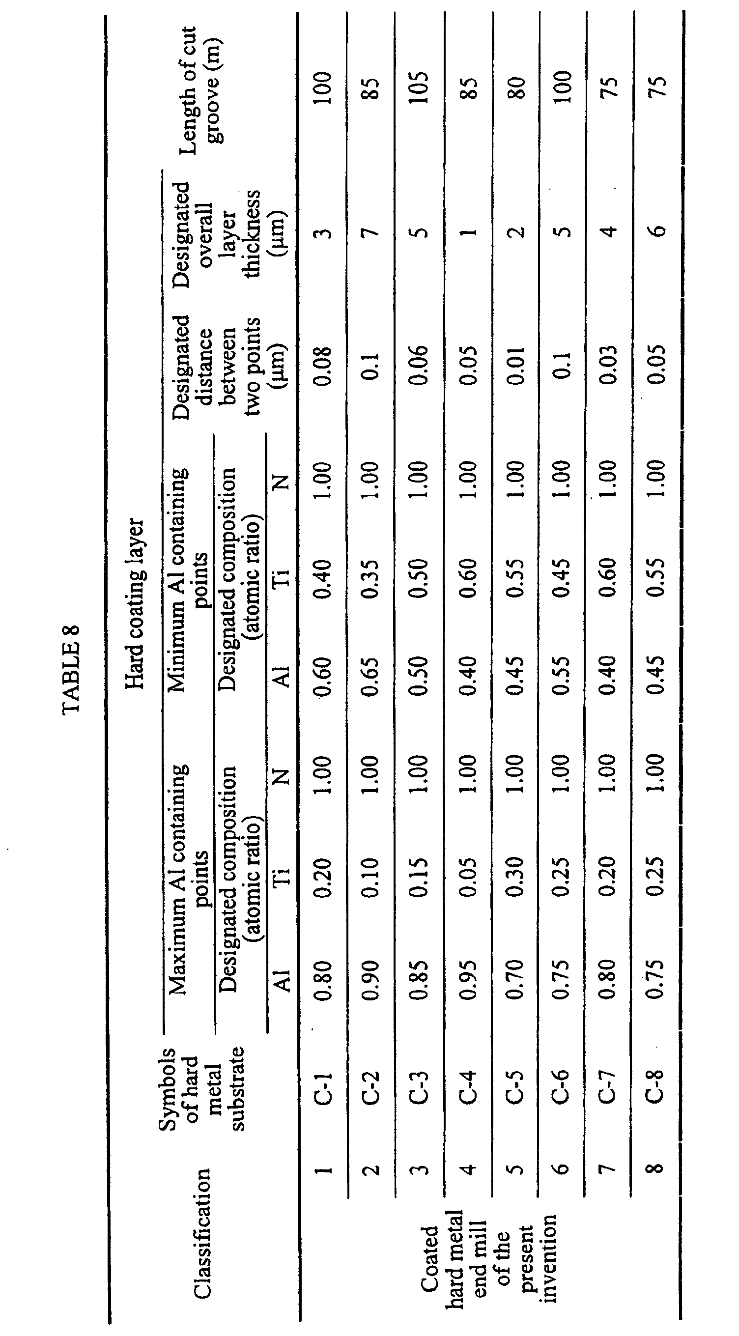
- Embodiment 1 a hard coating layer, which had component concentration profile in which the minimum aluminum containing points and the maximum aluminum containing points having a designated composition shown in TABLE 8 appear alternatingly and repeatedly at a designated interval also shown in TABLE 8 in the thickness direction, and the amount of contained aluminum (or titanium) is continuously changed from the maximum aluminum containing points to the minimum aluminum containing points and from the minimum aluminum containing points to the maximum aluminum containing points, and which had a designated overall layer thickness also shown in TABLE 8, was formed by a vapor deposition method, and thereby surface-coated hard metal end mills 1 to 8 of the present invention (hereinafter referred to as coated hard metal end mills of the present invention) having a shape whose schematic front view is shown in FIG. 4A, and whose schematic transverse cross-sectional view, specifically at the cutting edge, is shown in FIG. 4B, as the coated cutting tools of the present invention, were fabricated.
- coated hard metal end mills of the present invention having a shape whose schematic front view is shown in FIG. 4
- the surfaces of the hard metal substrates (end mills) C-1 to C-8 were subjected to ultrasonic cleaning in acetone, and then the hard metal substrates C-1 to C-8 were dried, and were accommodated in a conventional arc ion plating apparatus shown in FIG. 2.
- the conventional method was carried out under the same conditions as in the Embodiment 1 by which a hard coating layer, which had a designated composition and a designated layer thickness shown in TABLE 9, and which included an (Al, Ti)N layer in which composition was substantially constant in the direction of the layer thickness, was formed by a vapor deposition method, and thereby conventional surface-coated hard metal end mills 1 to 8 (hereinafter referred to as conventional coated hard metal end mills), as conventional coated cutting tools, were fabricated.
- a hard coating layer which had a designated composition and a designated layer thickness shown in TABLE 9, and which included an (Al, Ti)N layer in which composition was substantially constant in the direction of the layer thickness
- the coated hard metal end mills 1 to 8 of the present invention and the conventional coated hard metal end mills 1 to 8 were subjected to dry, high-speed, and groove formation cutting tests in which workpieces of tool steel were machined under the following conditions,
- coated hard metal end mills 4 to 6 of the present invention and the conventional coated hard metal end mills 4 to 6 were subjected to dry, high-speed, and groove formation cutting tests in which workpieces of stainless steel were machined under the following conditions,
- coated hard metal end mills 7 and 8 of the present invention and the conventional coated hard metal end mills 7 and 8 were subjected to dry, high-speed, and groove formation cutting tests in which workpieces of alloy steel were machined under the following conditions,
- the three types of sintered bars i.e., the bars having a diameter of 8 mm (hard metal substrates C-1 to C-3), the bars having a diameter of 13 mm (hard metal substrates C-4 to C-6), and the bars having a diameter of 26 mm (hard metal substrates C-7 and C-8), fabricated in Embodiment 2 were subjected to grinding so as to obtain hard metal substrates (drills) D-1 to D-8, and more specifically, to obtain hard metal substrates D-1 to D-3 having a fluted portion size of 4 mm ⁇ 13 mm (diameter ⁇ length), hard metal substrates D-4 to D-6 having a fluted portion size of 8 mm ⁇ 22 mm, and hard metal substrates D-7 and D-8 having a fluted portion size of 16 mmx45 mm.
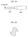
- Embodiment 1 a hard coating layer, which had component concentration profile in which the minimum aluminum containing points and the maximum aluminum containing points having a designated composition shown in TABLE 10 appear alternatingly and repeatedly at a designated interval also shown in TABLE 10 in the thickness direction, and the amount of contained aluminum (or titanium) is continuously changed from the maximum aluminum containing points to the minimum aluminum containing points and from the minimum aluminum containing points to the maximum aluminum containing points, and which had a designated overall layer thickness also shown in TABLE 10, was formed by a vapor deposition method, and thereby surface-coated hard metal drills 1 to 8 of the present invention (hereinafter referred to as coated hard metal drills of the present invention) having a shape whose schematic front view is shown in FIG. 5A, and whose schematic transverse cross-sectional view, specifically at the fluted portion, is shown in FIG 5B, as the coated cutting tools of the present invention, were fabricated.
- coated hard metal drills of the present invention having a shape whose schematic front view is shown in FIG. 5A, and
- honing processes were applied to the surfaces of the hard metal substrates (drills) D-1 to D-8, the hard metal substrates D-1 to D-8 were subjected to ultrasonic cleaning in acetone, and then the hard metal substrates D-1 to D-8 were dried, and were accommodated in a conventional arc ion plating apparatus shown in FIG 2.
- the conventional method was carried out under the same conditions as in the Embodiment 1 by which a hard coating layer, which had a designated composition and a designated layer thickness shown in TABLE 11, and which included an (Al, Ti)N layer in which composition was substantially constant in the direction of the layer thickness, was formed by a vapor deposition method, and thereby conventional surface-coated hard metal drills 1 to 8 (hereinafter referred to as conventional coated hard metal drills), as conventional coated cutting tools, were fabricated.
- a hard coating layer which had a designated composition and a designated layer thickness shown in TABLE 11, and which included an (Al, Ti)N layer in which composition was substantially constant in the direction of the layer thickness
- the coated hard metal drills 1 to 8 of the present invention and the conventional coated hard metal drills 1 to 8 were subjected to lubricated and high-speed drilling tests in which workpieces of tool steel were machined under the following conditions,
- coated hard metal drills 4 to 6 of the present invention and the conventional coated hard metal drills 4 to 6 were subjected to lubricated and high-speed drilling tests in which workpieces of ductile cast iron were machined under the following conditions,
- coated hard metal drills 7 and 8 of the present invention and the conventional coated hard metal drills 7 and 8 were subjected to lubricated and high-speed drilling tests in which workpieces of cast iron were machined under the following conditions,
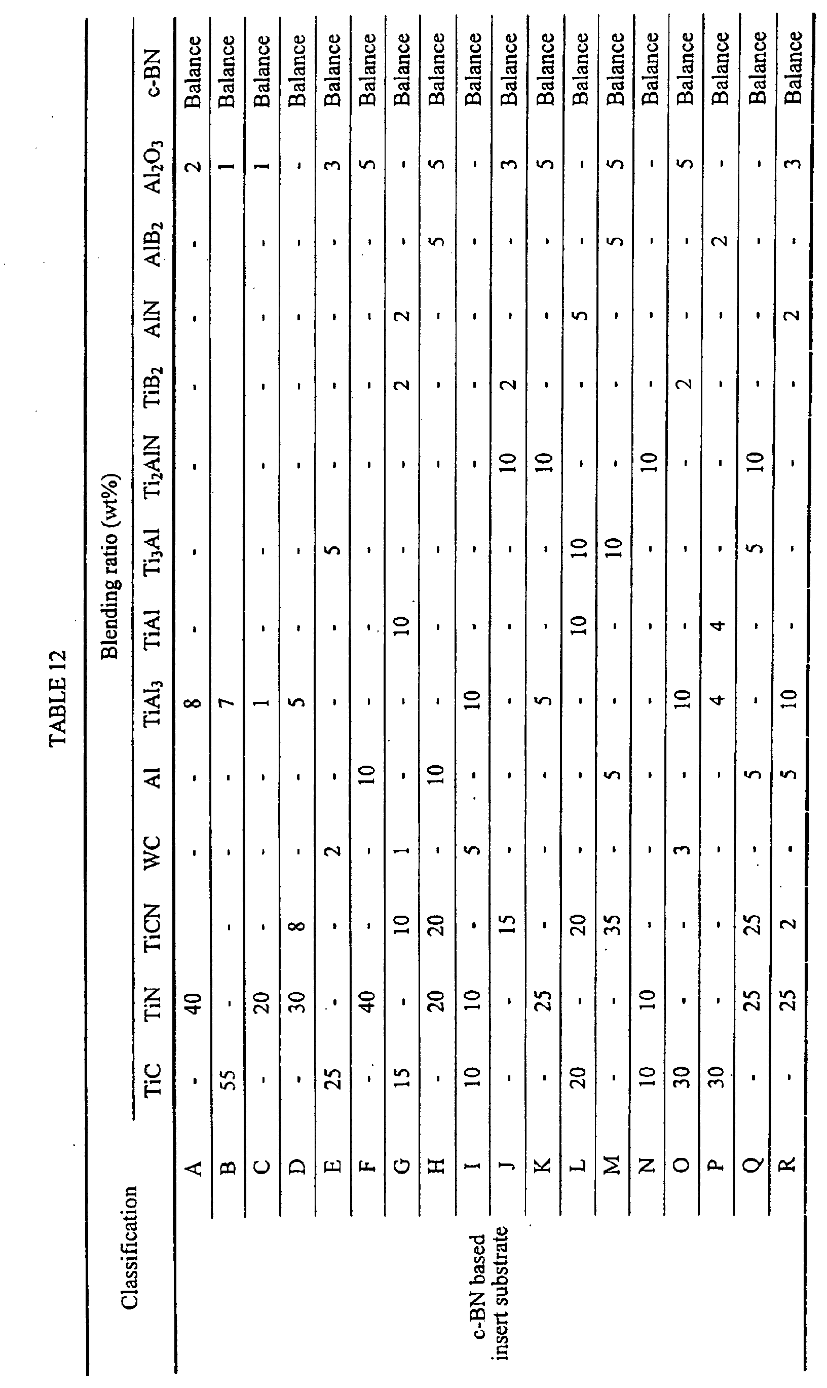
- Ingredient powders i.e., powders of c-BN, TiC, TiN, TiCN, WC, Al, Ti 3 Al, TiAl, and TiAl 3 , which are powders of intermetallic compounds of Ti and Al, compound metallic nitride having a composition formula of Ti 2 AlN, TiB 2 , AIN, AlB 2 , and Al 2 O 3 , all of which have an average grain size in a range from 0.5 to 4 ⁇ m, were prepared and mixed in accordance with blending ratios shown in TABLE 12.
- the ingredient powders were mixed under wet conditions using a ball mill for 72 hours, were dried, and were compacted under pressure of 100 MPa so as to form a green compact having a diameter of 50 mm and a thickness of 1.5 mm.
- the green compact was held in a vacuum at a pressure of 1Pa at a predetermined temperature in a range from 900 to 1300°C for 30 minutes so as to obtain a pre-sintered compact for forming a cutting piece.
- the pre-sintered compact was superposed on a supporting piece of a WC based hard metal plate which was separately prepared and had a diameter of 50 mm and a thickness of 2 mm, and which has a composition in which 8 wt% of Co and WC as the balance were included, and then the pre-sintered compact with the supporting piece was inserted into a conventional ultra-high pressure sintering apparatus, and was held under normal sintering conditions, i.e., a pressure of 5 GPa, a temperature in a range from 1200 to 1400°C, and a retention time of 0.5 hours, so as to be sintered under ultra-high pressure conditions.
- normal sintering conditions i.e., a pressure of 5 GPa, a temperature in a range from 1200 to 1400°C, and a retention time of 0.5 hours, so as to be sintered under ultra-high pressure conditions.
- a brazing portion (a comer portion) of a WC based hard metal insert body, which has a shape defined in the CIS standard-TNGA160408 (an equilateral triangle having 16 mm sides and a thickness of 4.76 mm) and has a composition in which 8 wt% of Co, 5 wt% of TaC, and WC as the balance were included, using a brazing agent of an Ag alloy having a composition in which 30 wt% of Cu, 28 wt% of Zn, 2 wt% of Ni, and Ag as the balance were included, and finish grinding was applied so as to obtain c-BN based insert substrates A to R.
- the c-BN based insert substrates A to R were subjected to ultrasonic cleaning in acetone, were dried, and were accommodated in the arc ion plating apparatus shown in FIGS. 1A and 1B, and then the method of the present invention was carried out under the same conditions as in Embodiment I by which a hard coating layer, which had component concentration profile in which the minimum aluminum containing points and the maximum aluminum containing points having a designated composition shown in TABLE 13 appear altematingly and repeatedly at a designated interval also shown in TABLE 13 in the thickness direction, and the amount of contained aluminum (or titanium) is continuously changed from the maximum aluminum containing points to the minimum aluminum containing points and from the minimum aluminum containing points to the maximum aluminum containing points, and which had a designated overall layer thickness also shown in TABLE 13, was formed by a vapor deposition method, and thereby coated c-BN based tools 1 to 18 of the present invention were fabricated.
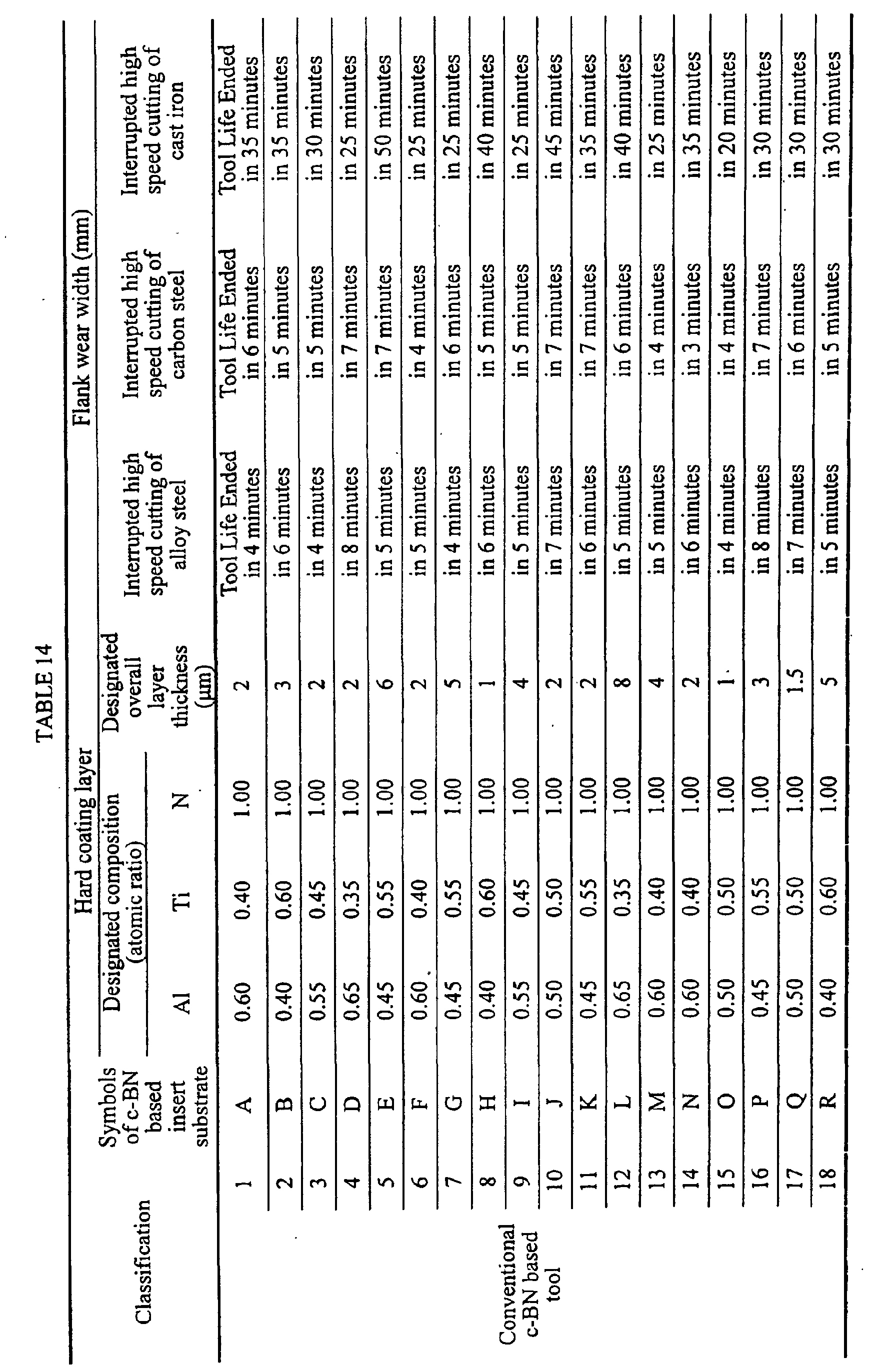
- conventional coated c-BN based tools 1 to 18 were fabricated under the same conditions as for the coated c-BN based tools 1 to 18 of the present invention except that a hard coating layer was formed on each of the c-BN based insert substrates A to R by accommodating the c-BN based insert substrates A to R in the conventional arc ion plating apparatus shown in FIG 2, by carrying out the conventional method under the same conditions as in the Embodiment 1 by which the hard coating layer, which had a designated composition and a designated layer thickness shown in TABLE 14, and which included an (Al, Ti)N layer in which composition was substantially constant in the direction of the layer thickness, was formed by a vapor deposition method.
- the coated c-BN based tools 1 to 18 of the present invention and the conventional coated c-BN based tools 1 to 18 were subjected to cutting tests by attaching each of them to a tip portion of a cutting tool made of tool steel using a fixing bridge and a screw.
- the detailed test conditions were set as follows:
- compositions of the minimum aluminum containing points and the minimum aluminum containing points of the hard coating layers which were included in the coated cutting tools of the present invention i.e., in the coated hard metal inserts 1 to 8 of the present invention, in the coated hard metal end mills 1 to 8 of the present invention, in the coated c-BN based tools 1 to 18 of the present invention, and the compositions of the hard coating layers which were included in the conventional coated cutting tools, i.e., in the conventional coated hard metal inserts 1 to 8, in the conventional coated hard metal end mills 1 to 8, in the conventional coated c-BN based tools 1 to 18, were measured using an Auger spectroscopic analyzer, and it was confirmed that the compositions were substantially the same as the designated compositions, respectively.
- the distances between the minimum aluminum containing points and the minimum aluminum containing points, and the overall thicknesses of the hard coating layers of the coated cutting tools of the present invention, and the thicknesses of the hard coating layers of the conventional coated cutting tools were measured using a scanning electron microscope, and it was confirmed that the distances and thicknesses were substantially the same as the designated ones, respectively.
- the coated cutting tools of the present invention which include the hard coating layer having a component concentration profile in which the maximum aluminum containing points and the minimum aluminum containing points appear alternatingly and repeatedly at a predetermined interval in a direction of thickness of the hard coating layer, and the amount of contained aluminum (or titanium) is continuously changed from the maximum aluminum containing points to the minimum aluminum containing points and from the minimum aluminum containing points to the maximum aluminum containing points, exhibit a superior wear resistance during a high speed cutting operation for steels and cast irons in which a significant amount of heat is generated, and in contrast, the conventional coated cutting tools, in which the hard coating layer is of the (Al, Ti)N layer in which composition is substantially constant in the direction of the layer thickness, exhibit excessive wear of the cutting edge and relatively short tool life due to insufficient high temperature properties during high speed cutting operations under high temperature conditions.
- the coated cutting tools of the present invention exhibit a superior wear resistance during a high speed cutting operation for various kinds of steels and cast irons, and exhibit a superior cutting performance for a long term, the coated cutting tools of the present invention can sufficiently meet the demand of high performance of the cutting operation apparatus, and demands of less power, less energy, and lower cost in cutting operations.
Landscapes
- Chemical & Material Sciences (AREA)
- Engineering & Computer Science (AREA)
- Mechanical Engineering (AREA)
- Chemical Kinetics & Catalysis (AREA)
- Materials Engineering (AREA)
- Metallurgy (AREA)
- Organic Chemistry (AREA)
- Cutting Tools, Boring Holders, And Turrets (AREA)
- Physical Vapour Deposition (AREA)
- Chemical Vapour Deposition (AREA)
- Drilling Tools (AREA)
Abstract
Description
| Classification | Blending ratio (wt%) | |||||||
| Co | TiC | TaC | NbC | VC | Cr3C2 | WC | ||
| Hard metal substrate (Insert) | A-1 | 5 | 2 | - | - | - - | - | Balance |
| A-2 | 6 | - | 1.5 | 1 | - | - | Balance | |
| A-3 | 6.5 | 0.6 | - | - | - | - | Balance | |
| A-4 | 7 | 0.4 | 1 | - | - | Balance | ||
| A-5 | 8 | - | - | - | 1 | 0.3 | Balance | |
| A-6 | 8.5 | - | 2.5 | - | - | - | Balance | |
| A-7 | 9.5 | - | - | - | - | 0.5 | Balance | |
| A-8 | 10.5 | 5 | - | 2 | - | - | Balance | |
| A-9 | 12 | 0.6 | 2.5 | - | - | - | Balance | |
| A-10 | 12.5 | 1.5 | - | - | - | - | Balance |
| Classification | Blending ratio (wt%) | ||||||||
| Co | Ni | ZrC | TaC | NbC | MO2C | WC | TiCN | ||
| Hard metal substrate (Insert) | B-1 | 13 | 5 | - | 10 | - | 10 | 16 | Balance |
| B-2 | 8 | 7 | - | 5 | - | 7.5 | - | Balance | |
| B-3 | 5 | - | - | - | - | 6 | 10 | Balance | |
| B-4 | 10 | 5 | - | 11 | 2 | - | - | Balance | |
| B-5 | 9 | 4 | 1 | 8 | - | 10 | 10 | Balance | |
| B-6 | 12 | 5.5 | - | 10 | - | 9.5 | 14.5 | Balance | |
| B-7 | 15 | 5 | 0.5 | 3 | 10 | - | 22 | Balance | |
| B-8 | 12 | 3 | - | 10 | 2 | 5 | - | Balance | |
| B-9 | - | 9 | 0.3 | 5 | - | - | 10 | Balance |







Claims (2)
- A surface-coated cutting tool member whose hard coating layer exhibiting a superior wear resistance during a high speed cutting operation, the surface-coated cutting tool member comprising:a tungsten carbide based cemented carbide substrate, a titanium carbonitride based cermet substrate, or a cubic boron nitride based sintered substrate; anda hard coating layer of a nitride compound containing aluminum and titanium, which is formed on a surface of the substrate using a physical vapor deposition method at an overall average thickness of 1 to 15 µm, whereinthe hard coating layer has a component concentration profile in which maximum aluminum containing points (minimum titanium containing points) and minimum aluminum containing points (maximum titanium containing points) appear alternatingly and repeatedly at a predetermined interval in a direction of thickness of the hard coating layer, and the amount of contained aluminum (or titanium) is continuously changed from the maximum aluminum containing points to the minimum aluminum containing points and from the minimum aluminum containing points to the maximum aluminum containing points,the maximum aluminum containing points satisfy a composition formula of (AlXTi1-X)N (where X indicates an atomic ratio of 0.70 to 0.95), the minimum aluminum containing points satisfy a composition formula of (AlYTi1-Y)N (where Y indicates an atomic ratio of 0.40 to 0.65), anda distance between one of the maximum aluminum containing points and adjacent one of the minimum aluminum containing points is from 0.01 to 0.1 µm.
- A method for forming a hard coating layer exhibiting a superior wear resistance during a high speed cutting operation on a surface of a cutting tool, the method comprising:mounting the cutting tool of a tungsten carbide based cemented carbide and/or a titanium carbonitride based cermet and/or a cubic boron nitride based sintered material on a turntable housed in an arc ion plating apparatus at a position radially away from a center axis of the turntable in a manner rotatable about an axis of the cutting tool;producing a nitrogen gas atmosphere as the reaction atmosphere in the arc ion plating apparatus; andgenerating arc discharge between a cathode electrode of an Al-Ti alloy for forming maximum aluminum containing points (minimum titanium containing points) and an anode electrode, and between another cathode electrode of a Ti-Al alloy for forming minimum aluminum containing points (maximum titanium containing points), which is disposed so as to oppose to the cathode electrode of an Al-Ti alloy with respect to the turntable, and another anode electrode, so that a hard coating layer having overall average thickness of 1 to 15 µm is formed, by a physical vapor deposition method, on the surface of the cutting tool being turned while rotating on the turntable about an axis of the cutting tool, whereinthe hard coating layer has a component concentration profile in which the maximum aluminum containing points (the minimum titanium containing points) and the minimum aluminum containing points (the maximum titanium containing points) appear alternatingly and repeatedly at a predetermined interval in a direction of thickness of the hard coating layer, and the amount of contained aluminum (or titanium) is continuously changed from the maximum aluminum containing points to the minimum aluminum containing points and from the minimum aluminum containing points to the maximum aluminum containing points,the maximum aluminum containing points satisfy a composition formula of (AlXTi1-X)N (where X indicates an atomic ratio of 0.70 to 0.95), the minimum aluminum containing points satisfy a composition formula of (AlYTi1-Y)N (where Y indicates an atomic ratio of 0.40 to 0.65), anda distance between one of the maximum aluminum containing points and adjacent one of the minimum aluminum containing points is from 0.01 to 0.1 µm.
Applications Claiming Priority (7)
| Application Number | Priority Date | Filing Date | Title |
|---|---|---|---|
| JP2002011478A JP3669334B2 (en) | 2002-01-21 | 2002-01-21 | Surface-coated cemented carbide cutting tool with excellent wear resistance due to high-speed cutting and hard coating layer |
| JP2002011478 | 2002-01-21 | ||
| JP2002049893 | 2002-02-26 | ||
| JP2002049893 | 2002-02-26 | ||
| JP2002060208 | 2002-03-06 | ||
| JP2002060208A JP3991262B2 (en) | 2002-02-26 | 2002-03-06 | A method of forming a hard coating layer on the cutting tool surface that exhibits excellent wear resistance in high-speed cutting |
| PCT/JP2003/000220 WO2003061884A1 (en) | 2002-01-21 | 2003-01-14 | Surface coated cutting tool member having hard coating layer exhibiting excellent abrasion resistance in high-speed cutting, and method for forming said hard coating layer on surface of cutting tool |
Publications (4)
| Publication Number | Publication Date |
|---|---|
| EP1470879A1 true EP1470879A1 (en) | 2004-10-27 |
| EP1470879A8 EP1470879A8 (en) | 2005-02-23 |
| EP1470879A4 EP1470879A4 (en) | 2008-01-02 |
| EP1470879B1 EP1470879B1 (en) | 2011-03-23 |
Family
ID=27617296
Family Applications (1)
| Application Number | Title | Priority Date | Filing Date |
|---|---|---|---|
| EP03701078A Expired - Lifetime EP1470879B1 (en) | 2002-01-21 | 2003-01-14 | Surface coated cutting tool member having hard coating layer exhibiting excellent abrasion resistance in high-speed cutting, and method for forming said hard coating layer on surface of cutting tool |
Country Status (7)
| Country | Link |
|---|---|
| US (1) | US7094479B2 (en) |
| EP (1) | EP1470879B1 (en) |
| KR (1) | KR100707755B1 (en) |
| CN (1) | CN100408237C (en) |
| AT (1) | ATE502710T1 (en) |
| DE (1) | DE60336453D1 (en) |
| WO (1) | WO2003061884A1 (en) |
Cited By (11)
| Publication number | Priority date | Publication date | Assignee | Title |
|---|---|---|---|---|
| EP1378304A3 (en) * | 2002-07-01 | 2005-10-12 | Seco Tools Ab | Wear resistant coating with enhanced toughness |
| EP1801260A1 (en) * | 2005-12-22 | 2007-06-27 | Mitsubishi Materials Silicon Corporation | Cutting tool made of surface-coated cubic boron nitride-based ultrahigh pressure sintered material |
| EP1867741A1 (en) * | 2006-06-15 | 2007-12-19 | Sandvik Intellectual Property AB | Insert for milling of cast iron |
| EP2011890A1 (en) * | 2007-06-01 | 2009-01-07 | Sandvik Intellectual Property AB | Fine grained cemented carbide with refined structure |
| EP2201153A4 (en) * | 2007-08-24 | 2010-09-08 | Seco Tools Ab | PLATE FOR MILLING THE CAST IRON |
| US7939186B2 (en) | 2006-05-26 | 2011-05-10 | Mitsubishi Materials Corporation | Cutting tool made of surface-coated cubic boron nitride-based ultra-high-pressure sintered material |
| US8084148B2 (en) | 2007-09-13 | 2011-12-27 | Seco Tools Ab | Insert for milling of cast iron |
| US8283058B2 (en) | 2007-06-01 | 2012-10-09 | Sandvik Intellectual Property Ab | Fine grained cemented carbide cutting tool insert |
| US8455116B2 (en) | 2007-06-01 | 2013-06-04 | Sandvik Intellectual Property Ab | Coated cemented carbide cutting tool insert |
| EP3031948B1 (en) | 2008-03-12 | 2017-03-15 | Kennametal Inc. | Body coated with hard material |
| EP3219420A4 (en) * | 2014-11-13 | 2018-06-27 | Mitsubishi Materials Corporation | Surface-coated cutting tool |
Families Citing this family (49)
| Publication number | Priority date | Publication date | Assignee | Title |
|---|---|---|---|---|
| US7250196B1 (en) * | 1999-10-26 | 2007-07-31 | Basic Resources, Inc. | System and method for plasma plating |
| US7144639B2 (en) * | 2002-01-31 | 2006-12-05 | Mitsubishi Materials Corporation | Surface-coated cutting tool member having hard coating layer and method for forming the hard coating layer on surface of cutting tool |
| US20030180450A1 (en) * | 2002-03-22 | 2003-09-25 | Kidd Jerry D. | System and method for preventing breaker failure |
| AU2003244324A1 (en) * | 2002-06-25 | 2004-01-06 | Mitsubishi Materials Corporation | Coated cutting tool member |
| US20050126497A1 (en) * | 2003-09-30 | 2005-06-16 | Kidd Jerry D. | Platform assembly and method |
| EP2308621B1 (en) * | 2004-01-30 | 2015-07-08 | Mitsubishi Materials Corporation | Surface-coated cutting tool made of hard metal |
| JP2006116831A (en) * | 2004-10-22 | 2006-05-11 | Sony Corp | Printer and printer control method |
| CN100528430C (en) * | 2004-06-18 | 2009-08-19 | 三菱麻铁里亚尔株式会社 | Surface-coated cutware and process for producing the same |
| DE102005032860B4 (en) * | 2005-07-04 | 2007-08-09 | Fraunhofer-Gesellschaft zur Förderung der angewandten Forschung e.V. | Hard material coated bodies and process for their production |
| SE529015C2 (en) * | 2005-09-09 | 2007-04-10 | Sandvik Intellectual Property | PVD coated cutting tool inserts made of cemented carbide |
| US7670674B2 (en) * | 2005-09-09 | 2010-03-02 | Sandvik Intellectual Property Ab | PVD coated cutting tool |
| SE530253C2 (en) * | 2005-12-14 | 2008-04-08 | Sandvik Intellectual Property | Carbide inserts, its manufacture and use for wear-requiring cutting and grooving in hot-strength super alloys and stainless steel |
| SE529431C2 (en) * | 2005-12-14 | 2007-08-07 | Sandvik Intellectual Property | Coated cemented carbide insert, ways of making this and its use for turning |
| JPWO2007111301A1 (en) * | 2006-03-28 | 2009-08-13 | 京セラ株式会社 | Surface coating tool |
| SE530517C2 (en) * | 2006-08-28 | 2008-06-24 | Sandvik Intellectual Property | Coated cemented carbide inserts, ways to manufacture them and their use for milling hard Fe-based alloys> 45 HRC |
| JP5096715B2 (en) | 2006-09-21 | 2012-12-12 | 株式会社神戸製鋼所 | Hard coating and hard coating tool |
| JP5125435B2 (en) * | 2006-12-13 | 2013-01-23 | 三菱マテリアル株式会社 | Porous titanium with low contact resistance |
| SE530944C2 (en) * | 2007-04-27 | 2008-10-28 | Sandvik Intellectual Property | Notch |
| SE0701320L (en) | 2007-06-01 | 2008-12-02 | Sandvik Intellectual Property | Coated cemented carbide for mold tool applications |
| KR100876366B1 (en) * | 2008-04-24 | 2008-12-31 | 한국야금 주식회사 | Multi-layer Hard Thin Films for Cutting Tools |
| WO2010150335A1 (en) * | 2009-06-22 | 2010-12-29 | 株式会社タンガロイ | Tool having coated cubic boron nitride sintered body |
| US8277958B2 (en) * | 2009-10-02 | 2012-10-02 | Kennametal Inc. | Aluminum titanium nitride coating and method of making same |
| RU2415198C1 (en) * | 2009-11-09 | 2011-03-27 | Федеральное государственное учреждение Российский научный центр "Курчатовский институт" | Multilayer coating on hard alloy tool for treatment of titanium alloys and procedure for its fabrication |
| JP4753143B2 (en) | 2009-12-21 | 2011-08-24 | 住友電工ハードメタル株式会社 | Surface coated cutting tool |
| KR101190324B1 (en) | 2010-02-11 | 2012-10-11 | 대구텍 유한회사 | Cutting tool |
| JP5574277B2 (en) * | 2010-10-29 | 2014-08-20 | 三菱マテリアル株式会社 | Cutting tool made of surface-coated cubic boron nitride-based ultra-high pressure sintered material with excellent peeling resistance |
| US8409702B2 (en) | 2011-02-07 | 2013-04-02 | Kennametal Inc. | Cubic aluminum titanium nitride coating and method of making same |
| JP5126702B1 (en) * | 2011-09-12 | 2013-01-23 | 三菱マテリアル株式会社 | Cutting tool made of cubic boron nitride based sintered material |
| DE102012107129A1 (en) * | 2012-08-03 | 2014-02-06 | Walter Ag | TiAIN coated tool |
| US9476114B2 (en) | 2012-08-03 | 2016-10-25 | Walter Ag | TiAlN-coated tool |
| US9126273B2 (en) * | 2012-12-17 | 2015-09-08 | Kennametal Inc | Tool for the cutting machining of workpieces and process for coating substrate bodies |
| US9103036B2 (en) | 2013-03-15 | 2015-08-11 | Kennametal Inc. | Hard coatings comprising cubic phase forming compositions |
| WO2014148488A1 (en) | 2013-03-22 | 2014-09-25 | 三菱マテリアル株式会社 | Surface-coated cutting tool |
| US9168664B2 (en) | 2013-08-16 | 2015-10-27 | Kennametal Inc. | Low stress hard coatings and applications thereof |
| US9896767B2 (en) | 2013-08-16 | 2018-02-20 | Kennametal Inc | Low stress hard coatings and applications thereof |
| JP6590255B2 (en) * | 2015-03-13 | 2019-10-16 | 三菱マテリアル株式会社 | Surface coated cutting tool with excellent chipping resistance due to hard coating layer |
| JP2016199793A (en) * | 2015-04-13 | 2016-12-01 | 株式会社神戸製鋼所 | Hard film |
| WO2017061328A1 (en) * | 2015-10-07 | 2017-04-13 | 株式会社タンガロイ | Coated cutting tool |
| JP6045010B1 (en) * | 2016-04-14 | 2016-12-14 | 住友電工ハードメタル株式会社 | Surface-coated cutting tool and manufacturing method thereof |
| JP7083448B2 (en) * | 2017-01-07 | 2022-06-13 | 株式会社タンガロイ | Cover cutting tool |
| US11524339B2 (en) * | 2018-08-24 | 2022-12-13 | Sumitomo Electric Hardmetal Corp. | Cutting tool |
| JP6825778B1 (en) | 2019-10-10 | 2021-02-03 | 住友電工ハードメタル株式会社 | Cutting tools |
| US11241745B2 (en) | 2019-10-10 | 2022-02-08 | Sumitomo Electric Hardmetal Corp. | Cutting tool including substrate and coating layer |
| US11358226B2 (en) | 2019-10-10 | 2022-06-14 | Sumitomo Electric Hardmetal Corp. | Cutting tool |
| EP3991888B1 (en) | 2019-10-10 | 2023-09-06 | Sumitomo Electric Hardmetal Corp. | Cutting tool |
| CN114173974B (en) | 2019-10-10 | 2024-03-15 | 住友电工硬质合金株式会社 | cutting tools |
| CN111690800B (en) * | 2020-06-16 | 2022-02-18 | 北京首钢吉泰安新材料有限公司 | Steel for cone pulley of wire drawing machine, preparation method of steel, cone pulley of wire drawing machine and application of cone pulley |
| JP7319600B6 (en) * | 2021-12-10 | 2023-08-18 | 株式会社タンガロイ | coated cutting tools |
| CN116083847B (en) * | 2023-01-16 | 2025-03-25 | 厦门金鹭特种合金有限公司 | Titanium diboride hard coating, coated tool and preparation method |
Family Cites Families (13)
| Publication number | Priority date | Publication date | Assignee | Title |
|---|---|---|---|---|
| JPS6362875A (en) * | 1986-09-01 | 1988-03-19 | Kobe Steel Ltd | Vacuum film forming device |
| JP2861113B2 (en) * | 1989-09-29 | 1999-02-24 | 住友電気工業株式会社 | Surface-coated carbide members for cutting and wear-resistant tools |
| EP0496053B1 (en) * | 1991-01-21 | 1995-07-26 | Balzers Aktiengesellschaft | Coated highly wear-resistant tool and physical coating method for highly wear-resistant tools |
| EP0592986B1 (en) * | 1992-10-12 | 1998-07-08 | Sumitomo Electric Industries, Limited | Ultra-thin film laminate |
| JP2979921B2 (en) * | 1993-09-30 | 1999-11-22 | 住友電気工業株式会社 | Ultra thin film laminate |
| JP3460288B2 (en) * | 1994-01-21 | 2003-10-27 | 住友電気工業株式会社 | Surface coating member with excellent wear resistance |
| US5700551A (en) * | 1994-09-16 | 1997-12-23 | Sumitomo Electric Industries, Ltd. | Layered film made of ultrafine particles and a hard composite material for tools possessing the film |
| JP3333081B2 (en) * | 1995-12-18 | 2002-10-07 | 東芝タンガロイ株式会社 | Crystal orientation high strength coated member |
| ES2192690T3 (en) * | 1996-09-03 | 2003-10-16 | Unaxis Balzers Ag | PART WITH PROTECTIVE COATING AGAINST WEAR. |
| JPH10317123A (en) * | 1997-05-16 | 1998-12-02 | Toshiba Tungaloy Co Ltd | Crystalline oriented hard coated member |
| JPH1161380A (en) * | 1997-08-20 | 1999-03-05 | Kobe Steel Ltd | Wear resistant multi-layer type hard coating film |
| WO1999040233A1 (en) * | 1998-02-04 | 1999-08-12 | Osg Corporation | Multilayer coated tool |
| SE9903089D0 (en) * | 1999-09-01 | 1999-09-01 | Sandvik Ab | Coated grooving or parting insert |
-
2003
- 2003-01-14 WO PCT/JP2003/000220 patent/WO2003061884A1/en not_active Ceased
- 2003-01-14 EP EP03701078A patent/EP1470879B1/en not_active Expired - Lifetime
- 2003-01-14 DE DE60336453T patent/DE60336453D1/en not_active Expired - Lifetime
- 2003-01-14 AT AT03701078T patent/ATE502710T1/en not_active IP Right Cessation
- 2003-01-14 US US10/501,805 patent/US7094479B2/en not_active Expired - Lifetime
- 2003-01-14 CN CNB038066130A patent/CN100408237C/en not_active Expired - Lifetime
- 2003-01-14 KR KR1020047011137A patent/KR100707755B1/en not_active Expired - Fee Related
Cited By (18)
| Publication number | Priority date | Publication date | Assignee | Title |
|---|---|---|---|---|
| EP1378304A3 (en) * | 2002-07-01 | 2005-10-12 | Seco Tools Ab | Wear resistant coating with enhanced toughness |
| EP1801260A1 (en) * | 2005-12-22 | 2007-06-27 | Mitsubishi Materials Silicon Corporation | Cutting tool made of surface-coated cubic boron nitride-based ultrahigh pressure sintered material |
| US8017225B2 (en) | 2005-12-22 | 2011-09-13 | Mitsubishi Materials Corporation | Cutting tool made of surface-coated cubic boron nitride-based ultrahigh pressure sintered material |
| US7939186B2 (en) | 2006-05-26 | 2011-05-10 | Mitsubishi Materials Corporation | Cutting tool made of surface-coated cubic boron nitride-based ultra-high-pressure sintered material |
| EP1867741A1 (en) * | 2006-06-15 | 2007-12-19 | Sandvik Intellectual Property AB | Insert for milling of cast iron |
| US7976607B2 (en) | 2006-06-15 | 2011-07-12 | Sandvik Intellectual Property Ab | Cemented carbide with refined structure |
| US8283058B2 (en) | 2007-06-01 | 2012-10-09 | Sandvik Intellectual Property Ab | Fine grained cemented carbide cutting tool insert |
| US7938878B2 (en) | 2007-06-01 | 2011-05-10 | Sandvik Intellectual Property Ab | Fine grained cemented carbide with refined structure |
| EP2287355A1 (en) * | 2007-06-01 | 2011-02-23 | Sandvik Intellectual Property AB | Fine grained cemented carbide with refined structure |
| EP2011890A1 (en) * | 2007-06-01 | 2009-01-07 | Sandvik Intellectual Property AB | Fine grained cemented carbide with refined structure |
| US8455116B2 (en) | 2007-06-01 | 2013-06-04 | Sandvik Intellectual Property Ab | Coated cemented carbide cutting tool insert |
| US9005329B2 (en) | 2007-06-01 | 2015-04-14 | Sandvik Intellectual Property Ab | Fine grained cemented carbide with refined structure |
| EP2201153A4 (en) * | 2007-08-24 | 2010-09-08 | Seco Tools Ab | PLATE FOR MILLING THE CAST IRON |
| US8084148B2 (en) | 2007-09-13 | 2011-12-27 | Seco Tools Ab | Insert for milling of cast iron |
| US8142621B2 (en) | 2007-09-13 | 2012-03-27 | Seco Tools Ab | Insert for milling of cast iron |
| EP3031948B1 (en) | 2008-03-12 | 2017-03-15 | Kennametal Inc. | Body coated with hard material |
| EP3219420A4 (en) * | 2014-11-13 | 2018-06-27 | Mitsubishi Materials Corporation | Surface-coated cutting tool |
| US10384269B2 (en) | 2014-11-13 | 2019-08-20 | Mitsubishi Materials Corporation | Surface-coated cutting tool |
Also Published As
| Publication number | Publication date |
|---|---|
| CN100408237C (en) | 2008-08-06 |
| US20050129986A1 (en) | 2005-06-16 |
| CN1642682A (en) | 2005-07-20 |
| EP1470879A8 (en) | 2005-02-23 |
| KR20040094673A (en) | 2004-11-10 |
| DE60336453D1 (en) | 2011-05-05 |
| WO2003061884A8 (en) | 2004-11-25 |
| ATE502710T1 (en) | 2011-04-15 |
| EP1470879B1 (en) | 2011-03-23 |
| KR100707755B1 (en) | 2007-04-17 |
| EP1470879A4 (en) | 2008-01-02 |
| WO2003061884A1 (en) | 2003-07-31 |
| US7094479B2 (en) | 2006-08-22 |
Similar Documents
| Publication | Publication Date | Title |
|---|---|---|
| US7094479B2 (en) | Surface-coated cutting tool member having hard coating layer exhibiting superior wear resistance during high speed cutting operation and method for forming hard coating layer on surface of cutting tool | |
| EP1535680B1 (en) | Coated cutting tool member | |
| JP3928481B2 (en) | Surface-coated cemented carbide cutting tool with excellent wear resistance under high-speed heavy cutting conditions. | |
| JP3928480B2 (en) | Surface coated cemented carbide cutting tool with excellent wear resistance with hard coating layer in high speed cutting | |
| US7144639B2 (en) | Surface-coated cutting tool member having hard coating layer and method for forming the hard coating layer on surface of cutting tool | |
| JP3844285B2 (en) | Surface-coated cemented carbide cutting tool with excellent wear resistance due to high-speed cutting and hard coating layer | |
| JP4007102B2 (en) | Surface coated cemented carbide cutting tool with excellent chipping resistance with hard coating layer under high speed heavy cutting conditions | |
| JP3985227B2 (en) | Surface coated cemented carbide cutting tool with excellent chipping resistance with hard coating layer under high speed heavy cutting conditions | |
| JP3982301B2 (en) | Surface coated cemented carbide cutting tool with excellent chipping resistance with hard coating layer under high speed heavy cutting conditions | |
| JP5099587B2 (en) | Surface-coated cutting tool with excellent fracture resistance due to hard coating layer | |
| JP4485146B2 (en) | Surface-coated cermet cutting tool with excellent wear resistance with a hard coating layer in high-speed cutting | |
| JP3928487B2 (en) | Surface coated cemented carbide cutting tool with excellent wear resistance with hard coating layer in high speed cutting | |
| HK1070612A (en) | Surface coated cutting tool member having hard coating layer exhibiting excellent abrasion resistance in high-speed cutting, and method for forming said hard coating layer on surface of cutting tool | |
| JP4206826B2 (en) | Surface coated cermet cutting tool with excellent wear resistance with high hard coating layer in high speed cutting | |
| JP4029323B2 (en) | Surface coated cemented carbide cutting tool with excellent chipping resistance with hard coating layer under high speed heavy cutting conditions | |
| JP3580271B2 (en) | Surface coated cemented carbide cutting tool with excellent chip slipperiness | |
| JP2004130495A (en) | Surface-coated cermet cutting tool with hard coating layer showing excellent chipping resistance under high-speed heavy cutting conditions | |
| JP3972293B2 (en) | Surface-coated cemented carbide cutting tool with excellent wear resistance under high-speed heavy cutting conditions. | |
| JP3972294B2 (en) | Surface coated cemented carbide cutting tool with excellent wear resistance with hard coating layer in high speed cutting | |
| JP3928434B2 (en) | Cutting tool made of surface-coated cemented carbide that exhibits excellent chipping resistance with a hard coating layer in intermittent heavy cutting | |
| JP3982347B2 (en) | Surface-coated cemented carbide cutting tool with excellent wear resistance under high-speed heavy cutting conditions. | |
| JP4029329B2 (en) | Surface coated cermet cutting tool with excellent wear resistance with high hard coating layer in high speed cutting | |
| JP3928497B2 (en) | Surface coated cemented carbide cutting tool with excellent chipping resistance with hard coating layer under high speed heavy cutting conditions | |
| JP2005224868A (en) | Surface-coated cermet cutting tool that exhibits excellent chipping resistance with a hard coating layer under high-speed heavy cutting conditions | |
| JP2005095986A (en) | Surface coated cermet cutting tool with excellent wear resistance with hard coating layer under high speed heavy cutting conditions |
Legal Events
| Date | Code | Title | Description |
|---|---|---|---|
| PUAI | Public reference made under article 153(3) epc to a published international application that has entered the european phase |
Free format text: ORIGINAL CODE: 0009012 |
|
| 17P | Request for examination filed |
Effective date: 20040717 |
|
| AK | Designated contracting states |
Kind code of ref document: A1 Designated state(s): AT BE BG CH CY CZ DE DK EE ES FI FR GB GR IE IT LI LU MC NL PT SE SI SK TR |
|
| D17D | Deferred search report published (deleted) | ||
| RAP1 | Party data changed (applicant data changed or rights of an application transferred) |
Owner name: MITSUBISHI MATERIALS KOBE TOOLS CORPORATION Owner name: MITSUBISHI MATERIALS CORPORATION |
|
| RIN1 | Information on inventor provided before grant (corrected) |
Inventor name: KONDO, AKIHIRO,MITSUBISHI MAT. KOBE TOOLS CORP. Inventor name: SATO, KAZUNORI,MITSUBISHI MAT. KOBE TOOLS CORP. Inventor name: TANAKA, YUSUKE,MITSUBISHI MAT. KOBE TOOLS CORP. |
|
| REG | Reference to a national code |
Ref country code: HK Ref legal event code: DE Ref document number: 1070612 Country of ref document: HK |
|
| A4 | Supplementary search report drawn up and despatched |
Effective date: 20071204 |
|
| RAP1 | Party data changed (applicant data changed or rights of an application transferred) |
Owner name: MITSUBISHI MATERIALS CORPORATION |
|
| 17Q | First examination report despatched |
Effective date: 20080409 |
|
| GRAP | Despatch of communication of intention to grant a patent |
Free format text: ORIGINAL CODE: EPIDOSNIGR1 |
|
| GRAS | Grant fee paid |
Free format text: ORIGINAL CODE: EPIDOSNIGR3 |
|
| RBV | Designated contracting states (corrected) |
Designated state(s): AT BE BG CH CY CZ DE DK EE ES FI FR GB GR HU IE IT LI LU MC NL PT SE SI SK TR |
|
| GRAA | (expected) grant |
Free format text: ORIGINAL CODE: 0009210 |
|
| AK | Designated contracting states |
Kind code of ref document: B1 Designated state(s): AT BE BG CH CY CZ DE DK EE ES FI FR GB GR HU IE IT LI LU MC NL PT SE SI SK TR |
|
| REG | Reference to a national code |
Ref country code: GB Ref legal event code: FG4D |
|
| REG | Reference to a national code |
Ref country code: CH Ref legal event code: EP |
|
| REG | Reference to a national code |
Ref country code: IE Ref legal event code: FG4D |
|
| REF | Corresponds to: |
Ref document number: 60336453 Country of ref document: DE Date of ref document: 20110505 Kind code of ref document: P |
|
| REG | Reference to a national code |
Ref country code: DE Ref legal event code: R096 Ref document number: 60336453 Country of ref document: DE Effective date: 20110505 |
|
| REG | Reference to a national code |
Ref country code: SE Ref legal event code: TRGR |
|
| REG | Reference to a national code |
Ref country code: NL Ref legal event code: VDEP Effective date: 20110323 |
|
| PG25 | Lapsed in a contracting state [announced via postgrant information from national office to epo] |
Ref country code: GR Free format text: LAPSE BECAUSE OF FAILURE TO SUBMIT A TRANSLATION OF THE DESCRIPTION OR TO PAY THE FEE WITHIN THE PRESCRIBED TIME-LIMIT Effective date: 20110624 |
|
| REG | Reference to a national code |
Ref country code: HK Ref legal event code: WD Ref document number: 1070612 Country of ref document: HK |
|
| PG25 | Lapsed in a contracting state [announced via postgrant information from national office to epo] |
Ref country code: SI Free format text: LAPSE BECAUSE OF FAILURE TO SUBMIT A TRANSLATION OF THE DESCRIPTION OR TO PAY THE FEE WITHIN THE PRESCRIBED TIME-LIMIT Effective date: 20110323 Ref country code: FI Free format text: LAPSE BECAUSE OF FAILURE TO SUBMIT A TRANSLATION OF THE DESCRIPTION OR TO PAY THE FEE WITHIN THE PRESCRIBED TIME-LIMIT Effective date: 20110323 Ref country code: BG Free format text: LAPSE BECAUSE OF FAILURE TO SUBMIT A TRANSLATION OF THE DESCRIPTION OR TO PAY THE FEE WITHIN THE PRESCRIBED TIME-LIMIT Effective date: 20110623 Ref country code: CY Free format text: LAPSE BECAUSE OF FAILURE TO SUBMIT A TRANSLATION OF THE DESCRIPTION OR TO PAY THE FEE WITHIN THE PRESCRIBED TIME-LIMIT Effective date: 20110323 Ref country code: AT Free format text: LAPSE BECAUSE OF FAILURE TO SUBMIT A TRANSLATION OF THE DESCRIPTION OR TO PAY THE FEE WITHIN THE PRESCRIBED TIME-LIMIT Effective date: 20110323 |
|
| PG25 | Lapsed in a contracting state [announced via postgrant information from national office to epo] |
Ref country code: BE Free format text: LAPSE BECAUSE OF FAILURE TO SUBMIT A TRANSLATION OF THE DESCRIPTION OR TO PAY THE FEE WITHIN THE PRESCRIBED TIME-LIMIT Effective date: 20110323 |
|
| PG25 | Lapsed in a contracting state [announced via postgrant information from national office to epo] |
Ref country code: PT Free format text: LAPSE BECAUSE OF FAILURE TO SUBMIT A TRANSLATION OF THE DESCRIPTION OR TO PAY THE FEE WITHIN THE PRESCRIBED TIME-LIMIT Effective date: 20110725 Ref country code: EE Free format text: LAPSE BECAUSE OF FAILURE TO SUBMIT A TRANSLATION OF THE DESCRIPTION OR TO PAY THE FEE WITHIN THE PRESCRIBED TIME-LIMIT Effective date: 20110323 |
|
| PG25 | Lapsed in a contracting state [announced via postgrant information from national office to epo] |
Ref country code: SK Free format text: LAPSE BECAUSE OF FAILURE TO SUBMIT A TRANSLATION OF THE DESCRIPTION OR TO PAY THE FEE WITHIN THE PRESCRIBED TIME-LIMIT Effective date: 20110323 Ref country code: CZ Free format text: LAPSE BECAUSE OF FAILURE TO SUBMIT A TRANSLATION OF THE DESCRIPTION OR TO PAY THE FEE WITHIN THE PRESCRIBED TIME-LIMIT Effective date: 20110323 Ref country code: ES Free format text: LAPSE BECAUSE OF FAILURE TO SUBMIT A TRANSLATION OF THE DESCRIPTION OR TO PAY THE FEE WITHIN THE PRESCRIBED TIME-LIMIT Effective date: 20110704 |
|
| PG25 | Lapsed in a contracting state [announced via postgrant information from national office to epo] |
Ref country code: NL Free format text: LAPSE BECAUSE OF FAILURE TO SUBMIT A TRANSLATION OF THE DESCRIPTION OR TO PAY THE FEE WITHIN THE PRESCRIBED TIME-LIMIT Effective date: 20110323 |
|
| PLBE | No opposition filed within time limit |
Free format text: ORIGINAL CODE: 0009261 |
|
| STAA | Information on the status of an ep patent application or granted ep patent |
Free format text: STATUS: NO OPPOSITION FILED WITHIN TIME LIMIT |
|
| 26N | No opposition filed |
Effective date: 20111227 |
|
| PG25 | Lapsed in a contracting state [announced via postgrant information from national office to epo] |
Ref country code: DK Free format text: LAPSE BECAUSE OF FAILURE TO SUBMIT A TRANSLATION OF THE DESCRIPTION OR TO PAY THE FEE WITHIN THE PRESCRIBED TIME-LIMIT Effective date: 20110323 |
|
| REG | Reference to a national code |
Ref country code: DE Ref legal event code: R097 Ref document number: 60336453 Country of ref document: DE Effective date: 20111227 |
|
| PG25 | Lapsed in a contracting state [announced via postgrant information from national office to epo] |
Ref country code: IT Free format text: LAPSE BECAUSE OF FAILURE TO SUBMIT A TRANSLATION OF THE DESCRIPTION OR TO PAY THE FEE WITHIN THE PRESCRIBED TIME-LIMIT Effective date: 20110323 |
|
| PG25 | Lapsed in a contracting state [announced via postgrant information from national office to epo] |
Ref country code: MC Free format text: LAPSE BECAUSE OF NON-PAYMENT OF DUE FEES Effective date: 20120131 |
|
| REG | Reference to a national code |
Ref country code: CH Ref legal event code: PL |
|
| REG | Reference to a national code |
Ref country code: IE Ref legal event code: MM4A |
|
| PG25 | Lapsed in a contracting state [announced via postgrant information from national office to epo] |
Ref country code: LI Free format text: LAPSE BECAUSE OF NON-PAYMENT OF DUE FEES Effective date: 20120131 Ref country code: CH Free format text: LAPSE BECAUSE OF NON-PAYMENT OF DUE FEES Effective date: 20120131 |
|
| PG25 | Lapsed in a contracting state [announced via postgrant information from national office to epo] |
Ref country code: IE Free format text: LAPSE BECAUSE OF NON-PAYMENT OF DUE FEES Effective date: 20120114 |
|
| PG25 | Lapsed in a contracting state [announced via postgrant information from national office to epo] |
Ref country code: TR Free format text: LAPSE BECAUSE OF FAILURE TO SUBMIT A TRANSLATION OF THE DESCRIPTION OR TO PAY THE FEE WITHIN THE PRESCRIBED TIME-LIMIT Effective date: 20110323 |
|
| PG25 | Lapsed in a contracting state [announced via postgrant information from national office to epo] |
Ref country code: LU Free format text: LAPSE BECAUSE OF NON-PAYMENT OF DUE FEES Effective date: 20120114 |
|
| PG25 | Lapsed in a contracting state [announced via postgrant information from national office to epo] |
Ref country code: HU Free format text: LAPSE BECAUSE OF FAILURE TO SUBMIT A TRANSLATION OF THE DESCRIPTION OR TO PAY THE FEE WITHIN THE PRESCRIBED TIME-LIMIT Effective date: 20030114 |
|
| REG | Reference to a national code |
Ref country code: FR Ref legal event code: PLFP Year of fee payment: 14 |
|
| REG | Reference to a national code |
Ref country code: FR Ref legal event code: PLFP Year of fee payment: 15 |
|
| REG | Reference to a national code |
Ref country code: FR Ref legal event code: PLFP Year of fee payment: 16 |
|
| PGFP | Annual fee paid to national office [announced via postgrant information from national office to epo] |
Ref country code: GB Payment date: 20180119 Year of fee payment: 16 |
|
| PGFP | Annual fee paid to national office [announced via postgrant information from national office to epo] |
Ref country code: SE Payment date: 20180119 Year of fee payment: 16 Ref country code: FR Payment date: 20180119 Year of fee payment: 16 |
|
| GBPC | Gb: european patent ceased through non-payment of renewal fee |
Effective date: 20190114 |
|
| PG25 | Lapsed in a contracting state [announced via postgrant information from national office to epo] |
Ref country code: FR Free format text: LAPSE BECAUSE OF NON-PAYMENT OF DUE FEES Effective date: 20190131 Ref country code: SE Free format text: LAPSE BECAUSE OF NON-PAYMENT OF DUE FEES Effective date: 20190115 |
|
| PG25 | Lapsed in a contracting state [announced via postgrant information from national office to epo] |
Ref country code: GB Free format text: LAPSE BECAUSE OF NON-PAYMENT OF DUE FEES Effective date: 20190114 |
|
| PGFP | Annual fee paid to national office [announced via postgrant information from national office to epo] |
Ref country code: DE Payment date: 20220119 Year of fee payment: 20 |
|
| REG | Reference to a national code |
Ref country code: DE Ref legal event code: R071 Ref document number: 60336453 Country of ref document: DE |