EP1468860A2 - Control method and apparatus for shifting means for axle coupling and differential locking - Google Patents
Control method and apparatus for shifting means for axle coupling and differential locking Download PDFInfo
- Publication number
- EP1468860A2 EP1468860A2 EP04008529A EP04008529A EP1468860A2 EP 1468860 A2 EP1468860 A2 EP 1468860A2 EP 04008529 A EP04008529 A EP 04008529A EP 04008529 A EP04008529 A EP 04008529A EP 1468860 A2 EP1468860 A2 EP 1468860A2
- Authority
- EP
- European Patent Office
- Prior art keywords
- slip
- lock
- speeds
- speed
- switching
- Prior art date
- Legal status (The legal status is an assumption and is not a legal conclusion. Google has not performed a legal analysis and makes no representation as to the accuracy of the status listed.)
- Granted
Links
Images

Classifications
-
- B—PERFORMING OPERATIONS; TRANSPORTING
- B60—VEHICLES IN GENERAL
- B60K—ARRANGEMENT OR MOUNTING OF PROPULSION UNITS OR OF TRANSMISSIONS IN VEHICLES; ARRANGEMENT OR MOUNTING OF PLURAL DIVERSE PRIME-MOVERS IN VEHICLES; AUXILIARY DRIVES FOR VEHICLES; INSTRUMENTATION OR DASHBOARDS FOR VEHICLES; ARRANGEMENTS IN CONNECTION WITH COOLING, AIR INTAKE, GAS EXHAUST OR FUEL SUPPLY OF PROPULSION UNITS IN VEHICLES
- B60K23/00—Arrangement or mounting of control devices for vehicle transmissions, or parts thereof, not otherwise provided for
- B60K23/08—Arrangement or mounting of control devices for vehicle transmissions, or parts thereof, not otherwise provided for for changing number of driven wheels, for switching from driving one axle to driving two or more axles
- B60K23/0808—Arrangement or mounting of control devices for vehicle transmissions, or parts thereof, not otherwise provided for for changing number of driven wheels, for switching from driving one axle to driving two or more axles for varying torque distribution between driven axles, e.g. by transfer clutch
-
- B—PERFORMING OPERATIONS; TRANSPORTING
- B60—VEHICLES IN GENERAL
- B60K—ARRANGEMENT OR MOUNTING OF PROPULSION UNITS OR OF TRANSMISSIONS IN VEHICLES; ARRANGEMENT OR MOUNTING OF PLURAL DIVERSE PRIME-MOVERS IN VEHICLES; AUXILIARY DRIVES FOR VEHICLES; INSTRUMENTATION OR DASHBOARDS FOR VEHICLES; ARRANGEMENTS IN CONNECTION WITH COOLING, AIR INTAKE, GAS EXHAUST OR FUEL SUPPLY OF PROPULSION UNITS IN VEHICLES
- B60K23/00—Arrangement or mounting of control devices for vehicle transmissions, or parts thereof, not otherwise provided for
- B60K23/04—Arrangement or mounting of control devices for vehicle transmissions, or parts thereof, not otherwise provided for for differential gearing
-
- B—PERFORMING OPERATIONS; TRANSPORTING
- B60—VEHICLES IN GENERAL
- B60W—CONJOINT CONTROL OF VEHICLE SUB-UNITS OF DIFFERENT TYPE OR DIFFERENT FUNCTION; CONTROL SYSTEMS SPECIALLY ADAPTED FOR HYBRID VEHICLES; ROAD VEHICLE DRIVE CONTROL SYSTEMS FOR PURPOSES NOT RELATED TO THE CONTROL OF A PARTICULAR SUB-UNIT
- B60W2510/00—Input parameters relating to a particular sub-units
- B60W2510/02—Clutches
- B60W2510/0241—Clutch slip, i.e. difference between input and output speeds
- B60W2510/025—Slip change rate
-
- B—PERFORMING OPERATIONS; TRANSPORTING
- B60—VEHICLES IN GENERAL
- B60W—CONJOINT CONTROL OF VEHICLE SUB-UNITS OF DIFFERENT TYPE OR DIFFERENT FUNCTION; CONTROL SYSTEMS SPECIALLY ADAPTED FOR HYBRID VEHICLES; ROAD VEHICLE DRIVE CONTROL SYSTEMS FOR PURPOSES NOT RELATED TO THE CONTROL OF A PARTICULAR SUB-UNIT
- B60W2520/00—Input parameters relating to overall vehicle dynamics
- B60W2520/26—Wheel slip
-
- B—PERFORMING OPERATIONS; TRANSPORTING
- B60—VEHICLES IN GENERAL
- B60W—CONJOINT CONTROL OF VEHICLE SUB-UNITS OF DIFFERENT TYPE OR DIFFERENT FUNCTION; CONTROL SYSTEMS SPECIALLY ADAPTED FOR HYBRID VEHICLES; ROAD VEHICLE DRIVE CONTROL SYSTEMS FOR PURPOSES NOT RELATED TO THE CONTROL OF A PARTICULAR SUB-UNIT
- B60W2520/00—Input parameters relating to overall vehicle dynamics
- B60W2520/28—Wheel speed
-
- B—PERFORMING OPERATIONS; TRANSPORTING
- B60—VEHICLES IN GENERAL
- B60W—CONJOINT CONTROL OF VEHICLE SUB-UNITS OF DIFFERENT TYPE OR DIFFERENT FUNCTION; CONTROL SYSTEMS SPECIALLY ADAPTED FOR HYBRID VEHICLES; ROAD VEHICLE DRIVE CONTROL SYSTEMS FOR PURPOSES NOT RELATED TO THE CONTROL OF A PARTICULAR SUB-UNIT
- B60W2710/00—Output or target parameters relating to a particular sub-units
- B60W2710/12—Differentials
-
- B—PERFORMING OPERATIONS; TRANSPORTING
- B60—VEHICLES IN GENERAL
- B60W—CONJOINT CONTROL OF VEHICLE SUB-UNITS OF DIFFERENT TYPE OR DIFFERENT FUNCTION; CONTROL SYSTEMS SPECIALLY ADAPTED FOR HYBRID VEHICLES; ROAD VEHICLE DRIVE CONTROL SYSTEMS FOR PURPOSES NOT RELATED TO THE CONTROL OF A PARTICULAR SUB-UNIT
- B60W2720/00—Output or target parameters relating to overall vehicle dynamics
- B60W2720/26—Wheel slip
Definitions
- the present invention relates to a method for automatic control of switching elements for activation of drive axles and locking differentials according to Preamble of claim 1. Furthermore relates to the present invention an apparatus for control of switching elements for connecting drive axles and Locking differentials, especially a device to carry out the method according to the invention.
- DE 4327507 describes C2 a device for automatic control of the clutches for actuating at least one axle lock and a longitudinal lock or the activation of the front wheel drive in the drive train of an all-wheel drive vehicle, where, based on the wheel speed signals, slip signals formed, compared with thresholds and such Control signals for the clutches are generated.
- each individual clutch Control module provided which control signals for generates this clutch, the control modules of the clutches control signals for the at least one axle lock for the clutch for actuating the longitudinal lock or for Submit engagement of the front wheel drive before the Control your own clutch.
- the slip signals are summed signals which separated by integration of the at least one axle lock, the longitudinal lock or the activation of the front wheel drive associated wheel speed differences formed and be compared with graded slip total threshold values, through the order and response time of the Locking the locks or engaging the front wheel drive is controlled.
- a device for automatic activation or deactivation of drive elements described a motor vehicle in particular for automatic Switching the drive on or off at least one Axle and / or locks for transfer case or differential, with sensors for the wheel speeds and for the Steering angle of the vehicle and with an electronic unit, which depends on the vehicle speed, the vehicle acceleration wheel slip and movement behavior of the vehicle as a function of the steering angle, the drive components individually, simultaneously or in a certain Order switches.
- the device for automatic connection or disconnection of drive elements adaptive electronics for the speeds of the wheels and for the steering angle of the vehicle. Accordingly, a blocking order is observed, whereby only due to slip on the front axle or slip between Rear axle and front axle is switched. road bumps cannot be filtered out directly; this is only indirectly higher by default Slip limits and low speed limits possible.
- the present invention is based on the object based on the prior art mentioned at the outset Process for automatic control of switching elements for connecting drive axles and locking differentials to indicate what the disadvantages of the state of the Technology avoids.
- Another object of the invention is a device for automatic control of switching elements for connecting drive axles and locking Differentials, especially for performing the invention Procedure.
- the blocking / switching order should be carried out different specification of the slip limits during the Operational changeable. Furthermore, a simple and faster evaluation of the data can be realized. Further is intended to be applied to a wide variety of multi-axis Vehicles will be possible without any problems.
- the device is preferably a control unit; the facilities contained therein are control modules.
- the device or Control unit for automatic control of switching elements for connecting drive axles and locking differentials a device or control module 1 for detection of input signals, such as wheel speeds, steering angle, Actual values for engine dust brake, retarder (if available), Brake pedal, gear, transfer gear, gear speeds, Status of the drive clutch or converter lock-up clutch, current engine torque, engine speed, and other relevant parameters.
- input signals such as wheel speeds, steering angle, Actual values for engine dust brake, retarder (if available), Brake pedal, gear, transfer gear, gear speeds, Status of the drive clutch or converter lock-up clutch, current engine torque, engine speed, and other relevant parameters.
- Some of this data can be transmitted via a data bus come from control units of other systems of the vehicle; however, should data not be available anyway, so will these are recorded directly using suitable facilities.
- FIG. 1 In the lower part of Figure 1 are those for the invention relevant components of a 4x4 vehicle. Shown are the front axle differential 29 with an actuator 25 for the corresponding switching element, the rear axle differential 27 with an actuator 23 for the corresponding a lock triggering switching element, the motor 31, the Gear 30, the transfer case 28 with the corresponding Actuator 24, as well as sensors 32, 33, 34, 35 the valves 17, 18, 19 for actuating the actuators 23, 24, 25 shown.
- the device contains 1 means for the automatic formation of deviations or correction signals for the respective input signals.
- deviations or correction signals for the respective input signals.
- For example can be the offset of the steering center position or the differences the tires can be determined.
- the determined Deviations are taken into account in the further calculations. This will result in the calculations more precisely and tighter limit values can be specified.
- the device 1 can have means for determining the status locks from wheel speeds (if it is not about proportionally controlled locks and switching elements acts), if their actuators are no longer controlled.
- the calculated lock status signal can in turn do this are used, possibly existing measured feedback signals check the lock status for plausibility.
- the invention contains Device a device 36 for determining the vehicle speed from the wheel speeds.
- this Means 36 are also all comparison or Limit speeds are determined, which for the limitation of functions are needed.
- the slip limit speeds i.e. the permissible Slip speeds
- these limits also Functions e.g. the vehicle speed and the drive torque could be. From the available ones Signals are also possible according to the invention, limit values for steering lock and lateral acceleration and to specify certain before reaching limit situations Unlock or suppress functions.
- a device 2, 3, 4 for slip calculation is provided for each switching / blocking element 27, 28, 29, a device 2, 3, 4 for slip calculation.
- the slip detection is for an automatic locking system the central point to recognize when a state occurs that requires automatic intervention. This is always the case if, for example, the required Drive torque no longer offset on the driven wheels can be. In this case, it can make sense connect additional axes to the transferable drive torque to increase.
- differentials have Property that in total only twice the minimum of the two transmissible output moments is transmitted. can i.e. the existing drive torque is not transmitted, this causes the drive wheels to slip.
- the slip calculation is according to the invention for each Switching / blocking element 27, 28, 29 performed.
- the slip speed occurring at the switching elements and the elimination of systematic interference is part of an advantageous training provided according to the invention to use additional sensor signals, such as steering angle, drive torque, wheel load distribution Etc.
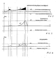
- devices 5, 6, 7 for comparing the actual slip speed with the limit values for the slip speed for each switching / blocking element previously in facilities 2, 3, 4 for slip calculation calculated slip speeds 46 permissible upper and extracted lower slip speeds 40, 41 which required for driving in a certain driving condition are.
- the Curve 46 is the one calculated by devices 2, 3, 4 Slip speed, with curves 40, 41 being a tolerance band the speed of the vehicle above ground define and limit values for train slip (leading) or Show thrust slip (lagging).
- limit values 40, 41 of the slip speed can be designed variable according to the invention and driving conditions, dynamic processes such as gear shifting, Load changes, etc. can be made dependent. ever better the limit values for the requirements of the driving condition are adjusted, the more precisely the control in the different vehicle conditions and driving situations. causes for different specifications of limit values 40, 41 can, for example, a gear shift impact, steep slope, Pull / push differentiation, suppression of resonances at certain speeds, terrain / road distinction, Differentiation between longitudinal differential / axle connection etc.
- the invention comprises Device at least one device 8, 9, 10 for selection the decisive slip speed, i.e. the actual hatching speed, which is the switching of a lock can trigger.
- these devices are as selectors designated.
- the filtering is carried out according to the invention by adding up (with discrete-time signals) or integrating the Slip speeds up to a predetermined limit 42, 43, 44, 45, the limit being 42, 43, 44, 45 preferably depending on the speed, the driving condition and other vehicle characteristics becomes. If a limit value is reached, a switching request is made triggered and the summation or integration stopped.
- the limit values represent a leading or lagging limit slip path.
- the limit 42, 43, 44, 45 is necessary because at existing blocking request but not issued switch permit the value would increase indefinitely, which is the case with arithmetic units leads to overflows. There would also be other disadvantages if the slip would disappear because of the shift request maintained for a very long time and undesirable would cause effects. According to the invention, the Sequence of lock controls based on the changes the limits 42, 43, 44, 45 are changed dynamically, which is not possible according to the state of the art.
- devices 14, 15, 16 are for generating of the control signal after consideration of further Factors are provided for each switching / blocking element.
- the Input signals for these facilities are Switching / locking requests resulting from the slip control result. Activation of the locks without consideration further parameters, could damage Guide powertrain components.
- the output signal of the devices 14, 15, 16 is a lock drive signal is output, which then immediately actuated the switching element.
- the invention is a device (selector) 20 for selection the most relevant lock among the locks to be triggered, a device 21 for control or limitation of the engine torque depending on the slip speed for the most relevant lock and facility 22 provided to limit the engine speed.
- the device 20 is with a device 21 for Determination of a required torque reduction connected, to the lock selected in the device 20 support. This will result in an output torque withdrawal request generated, this requirement in Dependence on the hatching speed for the most relevant Lock is calculated.
- the lock, the, for the Improving the current driving condition is the most important and has the greatest effect, should primarily be switched on be supported by generating a request to reduce the engine torque.
- the reduction requirement must be correspondingly smaller (more careful) then fail, especially in steep Terrain unpleasant dips in the drive torque and thus avoid getting caught or stalling the engine.
- the torque reduction preferably only starts at relative high exceedances of the slip threshold values.
- a Motor torque limitation can be carried out.
- the device 22 only requests to the Engine that is compatible with other systems of the Vehicle. So it may be that a gear shift or a request from ABS during braking higher priority must be given. Furthermore, there is an intervention on the engine only makes sense if this is a positive one Delivers drive torque.
- FIG 1 an arrangement for 4 x 4 vehicles is shown. With 8 x 8 vehicles, there are up to seven Locking / switching functions in the drivetrain, three longitudinal differentials with locks and four transverse differentials with locks. Corresponding the number of locks is there for each lock / switching function Facilities that the respective lock operate, which can always be essentially the same.
- the present invention can also be used with 12 x 12 vehicles applied or used; in advantageous Such vehicles can also be used as two sub-vehicles represent being a parent coordinator for the 'central longitudinal lock effective on both halves of the vehicle is provided, which is in one of the two control units is integrated.
- a requested lock is activated, then it is usually for a defined distance or at least kept on for a certain amount of time to give a vehicle the opportunity to move out of range to come out with poor traction.
- longitudinal locking must be switched on as long as cross locks are active are no longer activated, but not yet switched off are (in the event that the cross locks claw locks are).
Abstract
Description
Die vorliegende Erfindung betrifft ein Verfahren zur
selbsttätigen Steuerung von Schaltelementen zur Zuschaltung
von Antriebsachsen und Sperren von Differentialen gemäß dem
Oberbegriff des Patentanspruchs 1. Des weiteren betrifft
die vorliegende Erfindung eine Vorrichtung zur Steuerung
von Schaltelementen zur Zuschaltung von Antriebsachsen und
Sperren von Differentialen, insbesondere eine Vorrichtung
zur Durchführung des erfindungsgemäßen Verfahrens.The present invention relates to a method for
automatic control of switching elements for activation
of drive axles and locking differentials according to
Preamble of
Vorrichtungen zur Steuerung von Schaltelementen im Antriebsstrang eines Kraftfahrzeugs sind aus dem Stand der Technik bekannt. Beispielsweise beschreibt die DE 4327507 C2 eine Vorrichtung zur selbsttätigen Steuerung der Kupplungen zur Betätigung wenigstens einer Achsquersperre sowie einer Längssperre oder der Zuschaltung des Vorderradantriebs im Antriebsstrang eines allradangetriebenen Fahrzeugs, wobei ausgehend von den Raddrehzahlsignalen Schlupfsignale gebildet, mit Schwellenwerten verglichen und so Steuersignale für die Kupplungen erzeugt werden.Devices for controlling switching elements in the drive train of a motor vehicle are from the state of the Technology known. For example, DE 4327507 describes C2 a device for automatic control of the clutches for actuating at least one axle lock and a longitudinal lock or the activation of the front wheel drive in the drive train of an all-wheel drive vehicle, where, based on the wheel speed signals, slip signals formed, compared with thresholds and such Control signals for the clutches are generated.
Hierbei ist für jede einzelne Kupplung jeweils ein eigenes Steuermodul vorgesehen, welches Steuersignale für diese Kupplung erzeugt, wobei die Steuermodule der Kupplungen für die wenigstens eine Achssperre auch Steuersignale für die Kupplung zur Betätigung der Längssperre oder zur Zuschaltung des Vorderradantriebs abgeben, bevor sie die eigene Kupplung ansteuern. Des weiteren ist vorgesehen, dass die Schlupfsignale Schlupfsummensignale sind, welche getrennt durch Integration der der wenigstens einen Achssperre, der Längssperre oder der Zuschaltung des Vorderradantriebs zugeordneten Raddrehzahldifferenzen gebildet und mit gestuften Schlupfsummenschwellenwerten verglichen werden, durch die die Reihenfolge und die Reaktionszeit der Sperrung der Sperren oder der Zuschaltung des Vorderradantriebs gesteuert wird.There is a separate one for each individual clutch Control module provided which control signals for generates this clutch, the control modules of the clutches control signals for the at least one axle lock for the clutch for actuating the longitudinal lock or for Submit engagement of the front wheel drive before the Control your own clutch. Furthermore, it is provided that the slip signals are summed signals which separated by integration of the at least one axle lock, the longitudinal lock or the activation of the front wheel drive associated wheel speed differences formed and be compared with graded slip total threshold values, through the the order and response time of the Locking the locks or engaging the front wheel drive is controlled.
Durch die Vorgehensweise gemäß DE 4327507 C2 wird sicherstellt, dass nicht immer die Sperre am schnellsten aktiviert wird, die den größten Schlupf aufweist, sondern dass diejenige Sperre vorher modulübergreifend von dem Modul, der den Sperrwunsch äußert, aktiviert wird, die in diesem Fall die größte Wirkung mit den wenigsten Nachteilen bringt. Wenn die erwartete Wirkung zu klein ist, dann wird die gewünschte moduleigene Sperre aktiviert. Des weiteren können mit diesem Verfahren nicht quantifizierbare Elastizitäten und Fahrbahnunebenheiten ausgefiltert werden. Nachteilig ist jedoch, dass viele Vergleiche und Berechnungen erforderlich sind, um die Sperrwünsche herauszufiltern. Zudem ist sie Reihenfolge der Sperrvorgänge fest vorgegeben und während des Betriebs nicht beeinflussbar.The procedure according to DE 4327507 C2 ensures that that the lock is not always activated the fastest that has the greatest slip, but that the lock previously cross-module from the module, who expresses the blocking request is activated, which in in this case the greatest effect with the fewest disadvantages brings. If the expected effect is too small, then will the desired module-specific lock is activated. Furthermore can not be quantified elasticities with this method and road bumps are filtered out. The disadvantage, however, is that many comparisons and calculations are required to filter out the blocking requests. In addition, it is a fixed order of locking operations and cannot be influenced during operation.
Im Rahmen der DE 3505455 A1 wird eine Vorrichtung zum automatischen Zu- oder Abschalten von Antriebselementen eines Kraftfahrzeuges beschrieben, insbesondere zum automatischen Zu- oder Abschalten des Antriebes wenigstens einer Achse und/oder von Sperren für Verteiler- bzw. Ausgleichsgetriebe, mit Sensoren für die Raddrehzahlen und für den Lenkwinkel des Fahrzeuges und mit einer Elektronikeinheit, welche abhängig von der Fahrzeuggeschwindigkeit, der Fahrzeugbeschleunigung dem Radschlupf und vom Bewegungsverhalten des Fahrzeugs als Funktion des Lenkwinkels die Antriebskomponenten einzeln, gleichzeitig oder in einer bestimmten Reihenfolge schaltet. Ferner weist die Vorrichtung zum automatischen Zu- oder Abschalten von Antriebselementen eine adaptiv arbeitende Anpassungselektronik für die Drehzahlen der Räder und für den Lenkwinkel des Fahrzeugs auf. Demnach wird eine Sperrreihenfolge eingehalten, wobei nur aufgrund von Schlupf an der Vorderachse bzw. Schlupf zwischen Hinterachse und Vorderachse geschaltet wird. Fahrbahnunebenheiten können nicht direkt ausgefiltert werden; dies ist nur indirekt durch Vorgabe entsprechend hoher Schlupfgrenzen und niedriger Geschwindigkeitsgrenzwerte möglich.In the context of DE 3505455 A1, a device for automatic activation or deactivation of drive elements described a motor vehicle, in particular for automatic Switching the drive on or off at least one Axle and / or locks for transfer case or differential, with sensors for the wheel speeds and for the Steering angle of the vehicle and with an electronic unit, which depends on the vehicle speed, the vehicle acceleration wheel slip and movement behavior of the vehicle as a function of the steering angle, the drive components individually, simultaneously or in a certain Order switches. Furthermore, the device for automatic connection or disconnection of drive elements adaptive electronics for the speeds of the wheels and for the steering angle of the vehicle. Accordingly, a blocking order is observed, whereby only due to slip on the front axle or slip between Rear axle and front axle is switched. road bumps cannot be filtered out directly; this is only indirectly higher by default Slip limits and low speed limits possible.
Der vorliegenden Erfindung liegt die Aufgabe zugrunde, ausgehend von dem eingangs genannten Stand der Technik, ein Verfahren zur selbsttätigen Steuerung von Schaltelementen zur Zuschaltung von Antriebsachsen und Sperren von Differentialen anzugeben, welches die Nachteile des Standes der Technik vermeidet. Ein weiteres Ziel der Erfindung ist es, eine Vorrichtung zur selbsttätigen Steuerung von Schaltelementen zur Zuschaltung von Antriebsachsen und Sperren von Differentialen, insbesondere zur Durchführung des erfindungsgemäßen Verfahrens anzugeben.The present invention is based on the object based on the prior art mentioned at the outset Process for automatic control of switching elements for connecting drive axles and locking differentials to indicate what the disadvantages of the state of the Technology avoids. Another object of the invention is a device for automatic control of switching elements for connecting drive axles and locking Differentials, especially for performing the invention Procedure.
Insbesondere soll die Sperr/Schaltreihenfolge durch unterschiedliche Vorgabe der Schlupf-Grenzen während des Betriebs änderbar sein. Des weiteren soll eine einfache und schnellere Auswertung der Daten realisiert werden. Ferner soll eine Anwendung auf unterschiedlichste vielachsige Fahrzeuge problemlos möglich sein.In particular, the blocking / switching order should be carried out different specification of the slip limits during the Operational changeable. Furthermore, a simple and faster evaluation of the data can be realized. Further is intended to be applied to a wide variety of multi-axis Vehicles will be possible without any problems.
Diese Aufgabe wird für ein Verfahren durch die Merkmale
des Patentanspruchs 1 gelöst. Eine erfindungsgemäße Vorrichtung
ist Gegenstand des Patentanspruchs 17. Weitere
Ausgestaltungen und Vorteile gehen aus den entsprechenden
Unteransprüchen hervor.This task is for a procedure by the features
of
Das erfindungsgemäße Verfahren umfasst folgende
Schritte:
Ein besonders vorteilhafte Variante des hier vorgestellten
Verfahrens umfasst folgende zusätzliche Schritte:
Zudem wird eine Vorrichtung zur selbsttätigen Steuerung von Schaltelementen zur Zuschaltung von Antriebsachsen und Sperren von Differentialen vorgeschlagen, welche gemäß einer bevorzugten Ausführungsform eine Einrichtung zur Signalerfassung und zur Signalaufbereitung, eine Einrichtung zur Ermittlung der Fahrzeuggeschwindigkeit aus den Radgeschwindigkeiten und zur Ermittlung der Vergleichs- bzw. Grenz- und Schlupfgrenzgeschwindigkeiten sowie der Grenzwerte für Lenkeinschlag und Querbeschleunigung, eine Einrichtung zur Schlupfberechnung für jedes Schalt/Sperrelement, eine Einrichtung zum Vergleich der Ist- Schlupfgeschwindigkeit mit den Grenzwerten für die Schlupfgeschwindigkeit für jedes Schalt/Sperrelement, Einrichtungen zur Auswahl der schaltungsauslösenden Schlupfgeschwindigkeiten, Einrichtungen zur Filterung von Elastizitäten im Antriebsstrang und in den Reifen und von Unebenheiten und zur Erzeugung des Sperrwunsches für jedes Schalt/Sperrelement, eine Einrichtung zur Erzeugung des Ansteuerungssignales nach Berücksichtigung weiterer Faktoren für jedes Schalt/Sperrelement, eine Einrichtung zur Auswahl der relevantesten Sperre, eine Einrichtung zur Ansteuerung des Drehmomentes in Abhängigkeit von der Schlupfgeschwindigkeit für die relevanteste Sperre, und eine Einrichtung zur Begrenzung der Motordrehzahl nach erfolgter Sperre umfasst.In addition, a device for automatic control of switching elements for connecting drive axles and locking differentials proposed according to a preferred embodiment, a device for signal detection and for signal processing, a device to determine the vehicle speed from the wheel speeds and to determine the comparison or Limit and slip limit speeds as well as the limit values for steering lock and lateral acceleration, one device to calculate slip for each Switching / blocking element, a device for comparing the Actual slip speed with the limit values for the Slip speed for each switching / locking element, devices to select the shift-triggering slip speeds, Elasticity filtering devices in the drivetrain and in the tires and bumps and to generate the blocking request for everyone Switching / blocking element, a device for generating the Control signals after taking other factors into account for each switching / locking element, a device for Selection of the most relevant lock, a facility for Control of the torque depending on the Slip speed for the most relevant lock, and a device for limiting the engine speed after completion Lock includes.
Bei der Vorrichtung handelt es sich bevorzugterweise um ein Steuergerät; die darin enthaltenen Einrichtungen sind Steuermodule.The device is preferably a control unit; the facilities contained therein are control modules.
Die Erfindung wird im folgenden anhand der beigefügten Figuren am Beispiel eines 4x4 Fahrzeugs näher erläutert.The invention will now be described with reference to the accompanying Figures explained using the example of a 4x4 vehicle.
Es zeigen:
Gemäß der Erfindung umfasst die Vorrichtung bzw. das
Steuergerät zur selbsttätigen Steuerung von Schaltelementen
zur Zuschaltung von Antriebsachsen und Sperren von Differentialen
eine Einrichtung bzw. Steuermodul 1 zur Erfassung
von Eingangssignalen, wie Radgeschwindigkeiten, Lenkwinkel,
Istwerte für Motorstaubremse, Retarder (falls vorhanden),
Bremspedal, Getriebegang, Verteilergetriebegang, Getriebedrehzahlen,
Status der Fahrkupplung bzw. Wandlerüberbrückungskupplung,
aktuelles Motormoment, Motordrehzahl, sowie
weiterer relevanter Parameter.According to the invention, the device or
Control unit for automatic control of switching elements
for connecting drive axles and locking differentials
a device or
Hierbei kann ein Teil dieser Daten über einen Datenbus von Steuergeräten weiterer Systeme des Fahrzeugs stammen; sollten jedoch Daten nicht ohnehin vorliegen, so,werden diese mittels geeigneter Einrichtungen direkt erfasst.Some of this data can be transmitted via a data bus come from control units of other systems of the vehicle; however, should data not be available anyway, so will these are recorded directly using suitable facilities.
Im unteren Teil der Figur 1 sind die für die Erfindung
relevanten Bauteile eines 4x4 Fahrzeugs dargestellt. Gezeigt
sind das Vorderachsdifferential 29 mit einem Aktuator
25 für das entsprechende Schaltelement, das Hinterachsdifferential
27 mit einem Aktuator 23 für das entsprechende,
eine Sperre auslösende Schaltelement, der Motor 31, das
Getriebe 30, das Verteilergetriebe 28 mit dem entsprechenden
Aktuator 24, sowie Sensoren 32, 33, 34, 35. Ferner sind
die Ventile 17, 18, 19 zur Betätigung der Aktuatoren 23,
24, 25 gezeigt.In the lower part of Figure 1 are those for the invention
relevant components of a 4x4 vehicle. Shown
are the
Gemäß der Erfindung enthält die Einrichtung 1 Mittel
zur selbsttätigen Bildung von Abweichungen oder Korrektursignalen
für die jeweiligen Eingangssignale. Beispielsweise
können der Offset der Lenkungsmittenstellung oder die Unterschiede
der Bereifung ermittelt werden. Die ermittelten
Abweichungen werden in den weiteren Berechnungen berücksichtigt.
Dadurch werden die Ergebnisse der Berechnungen
genauer und es können engere Grenzwerte vorgegeben werden.
Ferner kann die Einrichtung 1 Mittel zum Ermitteln des Status
der Sperren aus den Radgeschwindigkeiten (wenn es sich
nicht um proportional gesteuerte Sperren und Schaltelemente
handelt), wenn deren Aktuatoren nicht mehr gesteuert sind.
Das errechnete Sperren - Statussignal kann wiederum dazu
benutzt werden, ev. vorhandene gemessene Rückmeldesignale
des Sperrenzustandes auf Plausibilität zu prüfen.According to the invention, the device contains 1 means
for the automatic formation of deviations or correction signals
for the respective input signals. For example
can be the offset of the steering center position or the differences
the tires can be determined. The determined
Deviations are taken into account in the further calculations.
This will result in the calculations
more precisely and tighter limit values can be specified.
Furthermore, the
Wie Figur 1 zu entnehmen, enthält die erfindungsgemäße
Vorrichtung eine Einrichtung 36 zur Ermittlung der Fahrzeuggeschwindigkeit
aus den Radgeschwindigkeiten. In dieser
Einrichtung 36 werden auch sämtliche Vergleichs- bzw.
Grenzgeschwindigkeiten ermittelt, welche für die Beschränkung
von Funktionen benötigt werden. In der Einrichtung 36
werden die Schlupfgrenzgeschwindigkeiten (also die zulässigen
Schlupfgeschwindigkeiten) für die verschiedenen Schaltelemente/Sperren
ermittelt, wobei diese Grenzwerte auch
Funktionen z.B. der Fahrzeuggeschwindigkeit und des Antriebsmomentes
sein können. Aus den zur Verfügung stehenden
Signalen ist es auch erfindungsgemäß möglich, Grenzwerte
für Lenkeinschlag und Querbeschleunigung abzuleiten und
vorzugeben, um vor dem Erreichen von Grenzsituationen bestimmte
Funktionen freizuschalten oder zu unterdrücken.As can be seen in FIG. 1, the invention contains
Device a
Eine vorteilhafte Weiterbildung der Erfindung sieht
vor, in der Einrichtung 36 einige der Grenzwerte mit geeigneten
kleinen Hysteresen zu versehen, um Pendelschaltungen
bei im praktischen Einsatz immer vorhandenen Schwingungen
von Signalen um einen Arbeitspunkt zu vermeiden.An advantageous development of the invention provides
before, in the
Des weiteren ist für jedes Schalt/Sperrelement 27, 28,
29 eine Einrichtung 2, 3, 4 zur Schlupfberechnung vorgesehen.
Für ein selbsttätiges Sperrsystem ist die Schlupfermittlung
der zentrale Punkt, um zu erkennen, wann ein Zustand
eintritt, der ein automatisches Eingreifen erfordert.
Das ist stets der Fall, wenn beispielsweise das geforderte
Antriebsmoment an den angetriebenen Rädern nicht mehr abgesetzt
werden kann. In diesem Fall kann es sinnvoll sein,
weitere Achsen zuzuschalten, um das übertragbare Antriebsmoment
zu erhöhen. Des weiteren haben Differentiale die
Eigenschaft, dass in Summe nur zweimal das Minimum der beiden
übertragbaren Ausgangsmomente übertragen wird. Kann
also das vorhandene Antriebsmoment nicht übertragen werden,
so kommt es zum Durchdrehen also Schlupfen von Antriebsrädern.Furthermore, for each switching / blocking
Andererseits gibt es Einflüsse, die Radgeschwindigkeitsverschiebungen zur Folge haben, ohne dass die Räder übermäßig durchdrehen.On the other hand there are influences, the wheel speed shifts result without the wheels freak excessively.
Um aus den Radgeschwindigkeiten den tatsächlichen
Schlupf richtig ermitteln zu können, müssen die systematischen
Störeinflüsse eliminiert werden. Das wird in den Einrichtungen
2, 3, 4 zur Schlupfberechnung durchgeführt. Einflüsse
kommen von der Lenkung, z.B. bei stationärer Kurvenfahrt,
da die inneren Räder langsamer sind, als die äußeren.
Bei Änderung des Lenkradwinkels ergeben sich, je nach
Lenkrollradius an den Rädern Zusatzgeschwindigkeiten, die
insbesondere bei Fahrzeugen mit Knicklenkung in Erscheinung
treten. An jedem Reifen entsteht je nach Antriebsmoment im
Verhältnis zur Normalkraft ein Reifenschlupf, der innerhalb
gewisser Grenzen zugelassen werden muss.To get the actual from the wheel speeds
To be able to determine slip correctly, the systematic
Interference can be eliminated. That will be in the
Die Schlupfberechnung wird erfindungsgemäß für jedes
Schalt/Sperrelement 27, 28, 29 durchgeführt. Für die Bildung
der an den Schaltelementen auftretenden Schlupfgeschwindigkeit
und die Beseitigung der systematischen Störeinflüsse
ist im Rahmen einer vorteilhaften Weiterbildung
der Erfindung vorgesehen, zusätzliche Sensorsignale zu verwenden,
wie beispielsweise Lenkwinkel, Antriebsmoment, Radlastverteilung
etc.The slip calculation is according to the invention for each
Switching / blocking
In den Einrichtungen 5, 6, 7 zum Vergleich der Ist-Schlupfgeschwindigkeit
mit den Grenzwerten für die Schlupfgeschwindigkeit
für jedes Schalt/Sperrelement werden aus
den in den Einrichtungen 2, 3, 4 zur Schlupfberechnung vorher
berechneten Schlupfgeschwindigkeiten 46 zulässige obere
und untere Schlupfgeschwindigkeiten 40, 41 extrahiert, die
für das Fahren in einem bestimmten Fahrzustand erforderlich
sind.In
Dies wird in Figur 2 graphisch veranschaulicht: Die
Kurve 46 ist die von den Einrichtungen 2, 3, 4 berechnete
Schlupfgeschwindigkeit, wobei die Kurven 40, 41 ein Toleranzband
um die Geschwindigkeit des Fahrzeuges über Grund
definieren und Grenzwerte für Zugschlupf (voreilend) bzw.
Schubschlupf (nacheilend) darstellen.This is illustrated graphically in FIG. 2: The
Die Vorgabe von Grenzwerten 40, 41 der Schlupfgeschwindigkeit kann erfindungsgemäß variabel gestaltet sein und von Fahrzustand, dynamischen Vorgängen, wie Getriebeschaltung, Lastwechsel, etc. abhängig gemacht werden. Je besser die Grenzwerte an die Erfordernisse des Fahrzustandes angepasst sind, um so genauer wird die Steuerung in den verschiedenen Fahrzeugzuständen und Fahrsituationen. Ursachen für unterschiedliche Vorgaben der Grenzwerte 40, 41 können beispielsweise ein Getriebeschaltstoß, Steilhangeinfahren, Zug/Schub-Unterscheidung, Unterdrückung von Resonanzen bei bestimmten Geschwindigkeiten, Gelände/Straße-Unterscheidung, Unterscheidung von Längsdifferential/Achszuschaltung etc. sein. The specification of limit values 40, 41 of the slip speed can be designed variable according to the invention and driving conditions, dynamic processes such as gear shifting, Load changes, etc. can be made dependent. ever better the limit values for the requirements of the driving condition are adjusted, the more precisely the control in the different vehicle conditions and driving situations. causes for different specifications of limit values 40, 41 can, for example, a gear shift impact, steep slope, Pull / push differentiation, suppression of resonances at certain speeds, terrain / road distinction, Differentiation between longitudinal differential / axle connection etc.
Das Verlassen des sogenannten Toleranzbandes 40, 41
kann in den zwei Richtungen Zugschlupf und Schubschlupf
erfolgen. Die nachfolgenden Berechnungen werden getrennt
für Zugschlupf und Schubschlupf durchgeführt, wobei in den
Figuren die Situation für Zugschlupf dargestellt wird.Leaving the so-called
Wie Figur 1 zu entnehmen, umfasst die erfindungsgemäße
Vorrichtung zumindest eine Einrichtung 8, 9, 10 zur Auswahl
der entscheidenden Schlupfgeschwindigkeit, d.h. der Ist-Schlupfgeschwindigkeit,
welche das Schalten einer Sperre
auslösen kann. In Figur 1 sind diese Einrichtungen als Selektoren
bezeichnet.As can be seen in FIG. 1, the invention comprises
Device at least one
Aus dem in den Einrichtungen 5, 6, 7 durchgeführten
Vergleich, bei dem ermittelt wird, ob der Schlupf über die
Schlupfgrenzwerte liegt, führen zu einem Schaltwunsch/Sperrwunsch
jene Zugschlupfgeschwindigkeiten die
Werte >0 haben, und auch jene Schubschlupfgeschwindigkeiten,
die Werte <0 haben. Damit kann schon eine Vorselektion
getroffen werden, da in der Praxis der Schlupf an einer
Komponente meist erstmals nur an einer Stelle auftritt und
dann infolge der Kopplung der Systeme und der Grenzwerte
schön langsam an allen Komponenten auftritt.From that carried out in the
Aus der meist aus fahrdynamischen Untersuchungen vorgegebenen Reihenfolge wie Sperren/Achszuschaltungen etc. zum Einsatz kommen sollen, ergibt sich für jede Sperre ein bestimmtes Intervall bzw. ein bestimmter Geschwindigkeitsbereich von Schlupfgeschwindigkeiten 46, der für die Auslösung der Sperre relevant ist. From the mostly given from driving dynamics studies Sequence like blocking / axis connections etc. should be used, results for each lock certain interval or a certain speed range of slip speeds 46, the one for triggering the lock is relevant.
Daher wird erfindungsgemäß vorgeschlagen, aus den Zugschlupfgeschwindigkeiten
jene auszuwählen, die den höchsten
Wert aufweist, bzw. bei den negativen Schubschlupfgeschwindigkeiten
jene auszuwählen, die den niedrigsten Wert aufweist,
wobei aber auch weitere Auswahlkriterien möglich
sind. Die ausgewählten Schlupfgeschwindigkeiten werden nun
den Einrichtungen 11, 12, 13 zur Filterung von Elastizitäten
und Unebenheiten zugeführt.It is therefore proposed according to the invention from the train slip speeds
to choose those that are the highest
Has value, or at the negative slip slip speeds
choose the one that has the lowest value,
but other selection criteria are also possible
are. The selected slip speeds are now
the
In diesen Einrichtungen 11, 12, 13 wird der nicht genau
bestimmbare Störeinfluss von Elastizitäten im Antriebsstrang,
im Reifen und von Unebenheiten der Fahrbahn nach
einem vordefinierten maximalen Ausmaß herausgefiltert. Alles
was darüber liegt, für zu einem Schaltwunsch oder dem
weiteren eingeschaltet Halten bereits geschalteter Elemente.
Die Filterung erfolgt gemäß der Erfindung durch Aufsummieren
(bei zeitdiskreten Signalen) bzw. Integrieren der
Schlupfgeschwindigkeiten bis zu einem vorgegebenen Grenzwert
42, 43, 44, 45, wobei der Grenzwert 42, 43, 44, 45
bevorzugterweise in Abhängigkeit von der Geschwindigkeit,
dem Fahrzustand und weiteren Fahrzeugeigenschaften vorgegeben
wird. Wird ein Grenzwert erreicht, so wird ein Schaltwunsch
ausgelöst und die Summierung bzw. Integration angehalten.
Die Grenzwerte stellen einen voreilenden bzw.
nacheilenden Grenzschlupfweg dar. Diese Verläufe sind somit
bei Quer- und Längssperre bis zur Begrenzung gleich, sofern
nicht unterschiedliche Schlupfgeschwindigkeiten ausgewählt
werden, wie Figur 2 (Verlauf für Quersperre) und Figur 3
(Verlauf für Längssperre) zu entnehmen ist. Mit 47 bzw. 48
sind die Schlupfwegkurven dargestellt, welche der Integration
bzw. der Summierung der Schlupfgeschwindigkeiten bei
Zug- bzw. Schubschlupf entsprechen. In these
Die Begrenzung 42, 43, 44, 45 ist erforderlich, da bei
vorhandenem Sperrwunsch aber nicht erteilter Schalterlaubnis
der Wert unendlich ansteigen würde, was bei Rechenwerken
zu Overflows führt. Zudem ergäben sich weitere Nachteile,
wenn der Schlupf verschwinden würde, da der Schaltwunsch
sehr lange noch aufrechterhalten und zu unerwünschten
Effekten führen würde. Gemäß der Erfindung kann die
Reihenfolge von Sperren-Ansteuerungen anhand vom Änderungen
der Begrenzungen 42, 43, 44, 45 dynamisch verändert werden,
was nach dem Stand der Technik nicht möglich ist.The
Durch die Auswahl der entscheidenden Schlupfgeschwindigkeiten
mittels der Einrichtungen 8, 9, 10 vor der Integration
in den Einrichtungen 11, 12 13 werden die nachfolgenden
Einrichtungen entkoppelt und können leicht ohne Auswirkung
auf die anderen Einrichtungen entfallen, wenn z.B.
eine Sperre nur manuell, nicht selbsttätig steuerbar ist
oder nicht vorhanden ist, die Auswirkung des auftretenden
Schlupfes aber auf andere Sperren Einfluss nehmen soll
(z.B. bei Fahrzeugen ohne Vorderachsquersperren). Die Vorselektion
durch die Einrichtungen 8, 9, 10 bewirkt, dass
wesentlich weniger Vergleiche notwendig sind, wodurch das
Steuerprogramm kleiner, schneller und transparenter gestaltet
wird.By choosing the decisive slip speeds
by means of
Gemäß Figur 1 sind Einrichtungen 14, 15, 16 zur Erzeugung
des Ansteuerungssignales nach Berücksichtigung weiterer
Faktoren für jedes Schalt/Sperrelement vorgesehen. Die
Eingangssignale für diese Einrichtungen sind
Schalt/Sperranforderungen, die aus der Schlupfsteuerung
resultieren. Eine Aktivierung der Sperren ohne Berücksichtigung
weiterer Parameter, könnte zu einer Beschädigung von
Komponenten des Antriebsstrangs führen. According to FIG. 1,
So ist es beispielsweise sinnvoll, die Schaltung von Klauensperren nur dann zuzulassen, wenn zum Schaltzeitpunkt das noch gefahrlos und ohne Schädigung von Antriebsstrangkomponenten möglich ist. Jede Schaltfunktion wird erfindungsgemäß mit Fahrzeuggeschwindigkeitsgrenzen und/oder Lenkwinkel- oder Fahrzeugquerbeschleunigungsgrenzwerten versehen. Des weiteren können weitere Kriterien bei einer Bremsung mit Betriebsbremse, Motorbremse, Retarder sowie Anforderungen aus ABS-Systemen berücksichtigt werden, mit dem Ziel, das Fahrzeug in allen Situationen möglichst stabil zu halten.For example, it makes sense to switch from Allow claw locks only if at the time of switching that is still safe and without damage to powertrain components is possible. Each switching function is according to the invention with vehicle speed limits and / or Steering angle or lateral vehicle acceleration limits Mistake. Furthermore, additional criteria can be used for a Braking with service brake, engine brake, retarder as well Requirements from ABS systems are taken into account with the goal of keeping the vehicle as stable as possible in all situations to keep.
In diesen Einrichtungen 14, 15, 16 kann auch eine manuelle
und abgesicherte Anforderung oder Verhinderung von
Sperren eingegeben werden. Für einige Fahrzeuge ist z.B.
die antriebsmomentabhängige Zuschaltung von Achsen bei
kleinen Gängen, um eine Überlastung von Antriebsachsen zu
vermeiden, erforderlich. Durch die Gewichtsverlagerung bei
Steigungsfahrten und über Differentiale gleich verteiltes
Antriebsmoment kann es ebenfalls zu erhöhtem Schlupf kommen,
sodass eine Steuerung, die den Einfluss quantifizieren
kann, in diesem Fall vorausschauend Längssperren einlegen
kann, wodurch die Sperren-Schalthäufigkeit reduziert wird.
Zudem ist es bei manchen Fahrzeugen sinnvoll, im Stillstand
und beim Anfahren einen definierten Sperrzustand herzustellen.In these
Als Ausgangssignal der Einrichtungen 14, 15, 16 wird
ein Sperren-Ansteuerungssignal ausgegeben, welches dann
unmittelbar die Betätigung des Schaltelementes veranlasst. The output signal of the
Gemäß einer bevorzugten Ausführungsform der vorliegenden
Erfindung ist eine Einrichtung (Selektor) 20 zur Auswahl
der relevantesten Sperre unter den auszulösenden Sperren,
eine Einrichtung 21 zur Ansteuerung bzw. Begrenzung
des Motordrehmomentes in Abhängigkeit von der Schlupfgeschwindigkeit
für die relevanteste Sperre und eine Einrichtung
22 zur Begrenzung der Motordrehzahl vorgesehen.According to a preferred embodiment of the present
The invention is a device (selector) 20 for selection
the most relevant lock among the locks to be triggered,
a
Bei Klauensperren gibt es ein aus den mechanischen Eigenschaften definiertes "Schaltfenster" der zulässigen Differenzdrehzahl an den Sperrenteilen in positiver und negativer Drehrichtung. Bei Sperren mit einstellbarem Sperrmoment ist die thermische Belastung der Reibbeläge das Schaltkriterium. Des weiteren sollen nicht allzu starke Schläge durch das Schalten von Antriebsstrangteilen in den Antriebsstrang und so in das Fahrzeug eingeleitet werden. Daher ist es sinnvoll, ab einer bestimmten Höhe der Schlupfgeschwindigkeit die Schaltung von Antriebsstrangteilen durch Rücknahme des Antriebsmomentes zu unterstützen.With claw locks there is one from the mechanical properties Defined "switching window" of the permissible differential speed on the lock parts in positive and negative Rotation. For locking with adjustable locking torque is the thermal load on the friction linings Switching criterion. Furthermore, not too strong Shocks from switching powertrain parts in the Powertrain and so introduced into the vehicle. Therefore, it makes sense to start from a certain height Slip speed the switching of powertrain parts support by reducing the drive torque.
Wie bereits erläutert, wird ein schlupfbasierender
Sperrwunsch bzw. Schaltwunsch an den Ausgängen der Einrichtungen
11, 12, 13 angezeigt. Der Sperrwunsch wird gemäß
Figur 1 auch an die Einrichtung 20 geleitet, wo die relevanteste
notwendige Sperre ausgewählt wird. Die Sperre, die
für die Verbesserung des aktuellen Fahrzustandes am wichtigsten
ist und größte Wirkung zeigt, soll zum Einschalten
vorrangig unterstützt werden. Eine mögliche Vorgehensweise
ist die Bildung des Absolutwertes der vorhandenen Schlupfgeschwindigkeiten
und die Auswahl der Schlupfgeschwindigkeit,
welche den größten Maximalwert aufweist. In vorteilhafter
Weise werden Informationen über den aktuellen Sperrzustand
auch der Einrichtung 20 zugeführt, so dass die bereits
gesperrten Systeme/Schaltelemente für die Auswahl und
die anschließende Momentenreduktion nicht in Betracht gezogen
werden.As already explained, it becomes a slip-based
Blocking request or switching request at the outputs of the
Die Einrichtung 20 ist mit einer Einrichtung 21 zur
Ermittlung einer erforderlichen Drehmomentreduktion verbunden,
um die in der Einrichtung 20 selektierte Sperre zu
unterstützen. Hierbei wird eine Abtriebsdrehmoment-Rücknahmeanforderung
generiert, wobei diese Anforderung in
Abhängigkeit von der Schlupfgeschwindigkeit für die relevanteste
Sperre berechnet wird. Die Sperre, die,für die
Verbesserung des aktuellen Fahrzustandes die wichtigste ist
und größte Wirkung zeigt, soll zum Einschalten vorrangig
unterstützt werden, indem eine Anforderung erzeugt wird,
das Motormoment zu reduzieren. Je mehr Sperren im Antriebstrang
bereits geschaltet sind, desto höher ist das bereits
übertragbare Drehmoment, bzw. umso schneller können nach
dem Schalten der ausstehenden Sperre die Drehmomente ansteigen.
Entsprechend kleiner (vorsichtiger) muss die Reduktionsanforderung
dann ausfallen, um speziell im steilen
Gelände unliebsame Einbrüche im Antriebsmoment und somit
das Hängenbleiben oder auch das Motorabwürgen zu vermeiden.
Bevorzugterweise setzt die Momentenrücknahme erst bei relativ
hohen Überschreitungen der Schlupfschwellwerte ein.The device 20 is with a
Bei Sperrsystemen, die auf Klauen basieren oder bei
proportionalen Sperrsystemen, die derart betrieben werden,
dass kein wesentlicher Schlupf im angeforderten Zustand
auftritt ist es sinnvoll, die Reduktion des Abtriebsmomentes
sofort wieder zurückzunehmen, wenn die gewünschte Sperre
eingelegt ist, wenn nicht noch weitere Anforderungen
anderer Schaltungen/Sperren vorliegen. Die in der Einrichtung
20 rückgeführten Ansteuersignale der Einrichtungen 14,
15, 16 ermöglichen die schnelle Beendigung der Drehmomentreduktion,
nachdem erkannt wurde, dass die gewünschte Sperre
nun zum Einlegen bereit ist.With locking systems based on claws or with
proportional locking systems operated in such a way
that no significant slip in the requested condition
if it occurs, it makes sense to reduce the output torque
withdraw immediately if the desired lock
is inserted, if not further requirements
other circuits / locks are present. The one in the facility
20 feedback control signals of the
Um Schwingungen im Antriebsstrang zu vermeiden, nachdem
eine Sperre geschaltet wird (da das zu übertragende
Drehmoment gemäß den Fahrerwünschen steigen wird), wird
gemäß der Erfindung vorgeschlagen, den Drehmomentanstieg
auf das vom Fahrer erwünschte Moment über eine kurze zeitliche
Rampe auszugleichen. Dies erfolgt in einer Einrichtung
22 zur Begrenzung der Motordrehzahl und/oder des Motormomentes,
welche auf Motordrehzahl und/oder Motormoment
eingreift, um eine möglichst komfortable Fahrt zu
gewährleisten.To avoid vibrations in the drive train after
a lock is switched (since the one to be transmitted
Torque will increase according to the driver's wishes)
proposed according to the invention, the torque increase
to the moment desired by the driver over a short time
Compensate ramp. This takes place in a
Treten zudem Traktionsprobleme auf, so wird ein überschüssiges Antriebsmoment in die Beschleunigung jenes Rades oder Achse geleitet, die das zur Verfügung stehende Moment nicht auf den Boden übertragen kann. Somit steigen in Teilen des Antriebsstranges die Drehzahlen und somit auch die Motordrehzahl unerwünschterweise an. Dieser Motordrehzahlanstieg muss meist nachfolgend wieder rückgängig gemacht werden.If traction problems also occur, there will be an excess Driving torque in the acceleration of that wheel or axis which is the available moment cannot transfer to the ground. Thus rise in parts the speed of the drive train and thus also the Engine speed undesirably on. This engine speed increase usually has to be subsequently undone become.
In diesem Fall ist es vorteilhaft, sofort nachdem eine
Antriebsmomentenreduktion in der Einrichtung 21 angefordert
wird, die vor dem Schlupfproblem herrschende Motordrehzahl
anzufordern und auf diesem Wert zu begrenzen. Nach erfolgter
Ansteuerung der gewünschten Sperre kann die Anforderung
der Motordrehzahlbegrenzung wieder langsam angehoben werden. In this case, it is advantageous to immediately after one
Drive torque reduction in the
Alternativ zur Motordrehzahlbegrenzung kann auch eine Motormomentbegrenzung durchgeführt werden.As an alternative to the engine speed limit, a Motor torque limitation can be carried out.
Von der Einrichtung 22 werden nur Anforderungen an den
Motor geleitet, die verträglich mit anderen Systemen des
Fahrzeuges sind. So kann es sein, dass einer Getriebeschaltung
oder einer Anforderung des ABS bei einer Bremsung eine
höhere Priorität einzuräumen ist. Des weiteren ist ein Eingriff
auf den Motor nur sinnvoll, wenn dieser ein positives
Antriebsmoment abgibt.The
In Figur 1 ist eine Anordnung für 4 x 4 Fahrzeuge gezeigt. Bei 8 x 8 Fahrzeugen gibt es bis zu sieben Sperr/Schaltfunktionen im Antriebsstrang, drei Längsdifferentiale mit Sperren und vier Querdifferentiale mit Sperren. Entsprechend der Anzahl der Sperren gibt es für jede Sperre/Schaltfunktion Einrichtungen, die die jeweilige Sperre bedienen, die im wesentlichen immer gleich sein können.In Figure 1, an arrangement for 4 x 4 vehicles is shown. With 8 x 8 vehicles, there are up to seven Locking / switching functions in the drivetrain, three longitudinal differentials with locks and four transverse differentials with locks. Corresponding the number of locks is there for each lock / switching function Facilities that the respective lock operate, which can always be essentially the same.
Die vorliegende Erfindung kann auch bei 12 x 12 Fahrzeugen angewandt bzw. eingesetzt werden; in vorteilhafter Weise lassen sich derartige Fahrzeuge auch als zwei Teilfahrzeuge darstellen, wobei ein übergeordneten Koordinator für die auf beide Fahrzeughälften wirksame' zentrale Längssperre vorgesehen ist, welcher in einem der beiden Steuergeräte integriert ist.The present invention can also be used with 12 x 12 vehicles applied or used; in advantageous Such vehicles can also be used as two sub-vehicles represent being a parent coordinator for the 'central longitudinal lock effective on both halves of the vehicle is provided, which is in one of the two control units is integrated.
Wenn eine angeforderte Sperre aktiviert wird, dann wird sie meist für eine definierte Wegstrecke oder zumindest für eine bestimmte Zeit eingeschaltet gehalten, um einem Fahrzeug die Möglichkeit zu geben, aus dem Bereich mit schlechter Traktion herauszukommen. Beim Lösen der Sperren kann erfindungsgemäß vorgesehen sein, dass Längssperren eingeschaltet sein müssen, solange Quersperren zwar nicht mehr angesteuert sind, jedoch noch nicht ausgeschaltet sind (für den Fall dass die Quersperren Klauensperren sind).If a requested lock is activated, then it is usually for a defined distance or at least kept on for a certain amount of time to give a vehicle the opportunity to move out of range to come out with poor traction. When loosening the Locking can be provided according to the invention that longitudinal locking must be switched on as long as cross locks are active are no longer activated, but not yet switched off are (in the event that the cross locks claw locks are).
Bei proportional steuerbaren Sperren werden diese langsam geöffnet, um zu erkennen, ob der Schlupf wieder unzulässig ansteigt. In the case of proportionally controllable locks, these are slowly opened to see if the slip again increases inadmissible.
- 11
- Einrichtung zur SignalerfassungDevice for signal acquisition
- 22
- Einrichtung zur SchlupfberechnungSlip calculation device
- 33
- Einrichtung zur SchlupfberechnungSlip calculation device
- 44
- Einrichtung zur SchlupfberechnungSlip calculation device
- 55
- Einrichtung zum Vergleichen der Ist- Schlupfgeschwindigkeit mit den Grenzwerten für die SchlupfgeschwindigkeitDevice for comparing the actual slip speed with the limit values for the slip speed
- 66
- Einrichtung zum Vergleichen der Ist- Schlupfgeschwindigkeit mit den Grenzwerten für die SchlupfgeschwindigkeitDevice for comparing the actual slip speed with the limit values for the slip speed
- 77
- Einrichtung zum Vergleichen der Ist- Schlupfgeschwindigkeit mit den Grenzwerten für die SchlupfgeschwindigkeitDevice for comparing the actual slip speed with the limit values for the slip speed
- 88th
- Einrichtung zur Auswahl der schaltungsauslösenden SchlupfgeschwindigkeitenDevice for selecting the circuit-triggering slip speeds
- 99
- Einrichtung zur Auswahl der schaltungsauslösenden SchlupfgeschwindigkeitenDevice for selecting the circuit-triggering slip speeds
- 1010
- Einrichtung zur Auswahl der schaltungsauslösenden SchlupfgeschwindigkeitenDevice for selecting the circuit-triggering slip speeds
- 1111
- Einrichtung zur Filterung von Elastizitäten und UnebenheitenDevice for filtering elasticities and bumps
- 1212
- Einrichtung zur Filterung von Elastizitäten und UnebenheitenDevice for filtering elasticities and bumps
- 1313
- Einrichtung zur Filterung von Elastizitäten und UnebenheitenDevice for filtering elasticities and bumps
- 1414
- Einrichtung zur Erzeugung des Ansteuerungssignales nach Berücksichtigung weiterer FaktorenDevice for generating the control signal after taking other factors into account
- 1515
- Einrichtung zur Erzeugung des Ansteuerungssignales nach Berücksichtigung weiterer FaktorenDevice for generating the control signal after taking other factors into account
- 1616
- Einrichtung zur Erzeugung des Ansteuerungssignales nach Berücksichtigung weiterer Faktoren Device for generating the control signal after taking other factors into account
- 1717
- VentilValve
- 1818
- VentilValve
- 1919
- VentilValve
- 2020
- Einrichtung zur Auswahl der relevantesten SperreFacility to select the most relevant lock
- 2121
- Einrichtung zur Ansteuerung des DrehmomentesDevice for controlling the torque
- 2222
- Einrichtung zur Begrenzung der MotordrehzahlDevice for limiting the engine speed
- 2323
- Aktuatoractuator
- 2424
- Aktuatoractuator
- 2525
- Aktuatoractuator
- 2727
- Hinterachsdifferentialrear differential
- 2828
- VerteilergetriebeTransfer Case
- 2929
- Vorderachsdifferentialfront axle
- 3030
- Getriebetransmission
- 3131
- Motorengine
- 3232
- Sensorsensor
- 3333
- Sensorsensor
- 3434
- Sensorsensor
- 3535
- Sensorsensor
- 3636
- Einrichtung zur Ermittlung der FahrzeuggeschwindigkeitDevice for determining the vehicle speed
- 4040
- Zulässige obere SchlupfgeschwindigkeitPermissible upper slip speed
- 4141
- Zulässige untere SchlupfgeschwindigkeitPermissible lower slip speed
- 4242
- Grenzwert für SchlupfwegLimit for slip path
- 4343
- Grenzwert für SchlupfwegLimit for slip path
- 4444
- Grenzwert für SchlupfwegLimit for slip path
- 4545
- Grenzwert für SchlupfwegLimit for slip path
- 4646
- Schlupfgeschwindigkeitslip velocity
- 4747
- SchlupfwegSchlupfweg
- 4848
- SchlupfwegSchlupfweg
Claims (19)
Applications Claiming Priority (2)
| Application Number | Priority Date | Filing Date | Title |
|---|---|---|---|
| DE10317450 | 2003-04-16 | ||
| DE10317450A DE10317450A1 (en) | 2003-04-16 | 2003-04-16 | Method and device for controlling switching elements for connecting drive axles and locking differentials |
Publications (3)
| Publication Number | Publication Date |
|---|---|
| EP1468860A2 true EP1468860A2 (en) | 2004-10-20 |
| EP1468860A3 EP1468860A3 (en) | 2006-05-24 |
| EP1468860B1 EP1468860B1 (en) | 2007-09-26 |
Family
ID=32892365
Family Applications (1)
| Application Number | Title | Priority Date | Filing Date |
|---|---|---|---|
| EP04008529A Expired - Fee Related EP1468860B1 (en) | 2003-04-16 | 2004-04-08 | Control method and apparatus for shifting means for axle coupling and differential locking |
Country Status (3)
| Country | Link |
|---|---|
| EP (1) | EP1468860B1 (en) |
| AT (1) | ATE374130T1 (en) |
| DE (2) | DE10317450A1 (en) |
Cited By (5)
| Publication number | Priority date | Publication date | Assignee | Title |
|---|---|---|---|---|
| EP1688334A1 (en) * | 2005-02-03 | 2006-08-09 | Dana Corporation | Automated inter-axle differential locking system |
| DE102009031500A1 (en) * | 2009-07-02 | 2011-01-05 | Magna Powertrain Ag & Co Kg | Wheel clutch controlling method for drive train of motor vehicle, involves providing operating condition of main clutch, and controlling wheel clutch based on determined clutch torque value when coupling impact risk criterion is fulfilled |
| US8635002B2 (en) | 2011-02-28 | 2014-01-21 | Engineering Center Steyr Gmbh & Co Kg | Control method for a coupling in the powertrain of a motor vehicle |
| US9046160B2 (en) | 2013-04-03 | 2015-06-02 | Caterpillar Inc. | Control system for differential of machine |
| EP3947001B1 (en) * | 2019-03-26 | 2024-02-28 | ZF Friedrichshafen AG | Method for controlling a driving dynamics function of a working machine |
Families Citing this family (2)
| Publication number | Priority date | Publication date | Assignee | Title |
|---|---|---|---|---|
| DE102017219271A1 (en) | 2017-10-26 | 2019-05-02 | Deere & Company | Method for operating a commercial vehicle with four-wheel drive and differential lock |
| DE102019203516A1 (en) * | 2019-03-15 | 2020-09-17 | Zf Friedrichshafen Ag | Drive system for a vehicle and method for the automatic actuation of a locking device |
Citations (4)
| Publication number | Priority date | Publication date | Assignee | Title |
|---|---|---|---|---|
| DE4427040A1 (en) * | 1994-07-29 | 1996-02-08 | Steyr Daimler Puch Ag | Control system for vehicle axle differential lock |
| DE19749919A1 (en) * | 1996-12-04 | 1998-06-10 | Steyr Daimler Puch Ag | Locking differential control for all-wheel drive (AWD) vehicle |
| WO2002020319A1 (en) * | 2000-09-09 | 2002-03-14 | Kelsey-Hayes Company | Rough road detection using suspension system information |
| US20020153770A1 (en) * | 2001-04-24 | 2002-10-24 | Fuji Jukogyo Kabushiki Kaisha | Vehicle behavior control apparatus |
Family Cites Families (1)
| Publication number | Priority date | Publication date | Assignee | Title |
|---|---|---|---|---|
| DE3505455A1 (en) * | 1985-02-16 | 1986-08-28 | Daimler-Benz Ag, 7000 Stuttgart | DEVICE FOR AUTOMATICALLY SWITCHING ON AND OFF OF DRIVE ELEMENTS OF A MOTOR VEHICLE |
-
2003
- 2003-04-16 DE DE10317450A patent/DE10317450A1/en not_active Withdrawn
-
2004
- 2004-04-08 AT AT04008529T patent/ATE374130T1/en not_active IP Right Cessation
- 2004-04-08 EP EP04008529A patent/EP1468860B1/en not_active Expired - Fee Related
- 2004-04-08 DE DE502004005056T patent/DE502004005056D1/en not_active Expired - Lifetime
Patent Citations (4)
| Publication number | Priority date | Publication date | Assignee | Title |
|---|---|---|---|---|
| DE4427040A1 (en) * | 1994-07-29 | 1996-02-08 | Steyr Daimler Puch Ag | Control system for vehicle axle differential lock |
| DE19749919A1 (en) * | 1996-12-04 | 1998-06-10 | Steyr Daimler Puch Ag | Locking differential control for all-wheel drive (AWD) vehicle |
| WO2002020319A1 (en) * | 2000-09-09 | 2002-03-14 | Kelsey-Hayes Company | Rough road detection using suspension system information |
| US20020153770A1 (en) * | 2001-04-24 | 2002-10-24 | Fuji Jukogyo Kabushiki Kaisha | Vehicle behavior control apparatus |
Cited By (6)
| Publication number | Priority date | Publication date | Assignee | Title |
|---|---|---|---|---|
| EP1688334A1 (en) * | 2005-02-03 | 2006-08-09 | Dana Corporation | Automated inter-axle differential locking system |
| DE102009031500A1 (en) * | 2009-07-02 | 2011-01-05 | Magna Powertrain Ag & Co Kg | Wheel clutch controlling method for drive train of motor vehicle, involves providing operating condition of main clutch, and controlling wheel clutch based on determined clutch torque value when coupling impact risk criterion is fulfilled |
| DE102009031500B4 (en) | 2009-07-02 | 2021-12-30 | Magna powertrain gmbh & co kg | Apparatus and method for controlling a four-wheel clutch |
| US8635002B2 (en) | 2011-02-28 | 2014-01-21 | Engineering Center Steyr Gmbh & Co Kg | Control method for a coupling in the powertrain of a motor vehicle |
| US9046160B2 (en) | 2013-04-03 | 2015-06-02 | Caterpillar Inc. | Control system for differential of machine |
| EP3947001B1 (en) * | 2019-03-26 | 2024-02-28 | ZF Friedrichshafen AG | Method for controlling a driving dynamics function of a working machine |
Also Published As
| Publication number | Publication date |
|---|---|
| EP1468860B1 (en) | 2007-09-26 |
| ATE374130T1 (en) | 2007-10-15 |
| EP1468860A3 (en) | 2006-05-24 |
| DE502004005056D1 (en) | 2007-11-08 |
| DE10317450A1 (en) | 2004-10-28 |
Similar Documents
| Publication | Publication Date | Title |
|---|---|---|
| EP1399327B1 (en) | Method for controlling a drivetrain on a motor vehicle | |
| WO2011131320A1 (en) | Device for operating a drive unit of a motor vehicle | |
| EP2495123B1 (en) | Control method for a coupling in the power train of a motor vehicle | |
| DE102019129534B4 (en) | VEHICLE CONTROL SYSTEM AND METHOD OF VEHICLE CONTROL ON A LOW FRICTION ROAD | |
| DE102016208077A1 (en) | Method for operating a motor vehicle with a brake holding assistant | |
| DE10325354A1 (en) | Method for operating a drive train of a motor vehicle | |
| WO2006119850A1 (en) | Method and apparatus for preventing undesired vehicle acceleration in the case of overrun shifting when travelling downhill | |
| DE102012222197A1 (en) | Method for distribution of drive torque to primary axle and secondary axle of motor vehicle, involves limiting maximum adjustable torque of secondary axle to certain maximum value by torque distribution device | |
| EP1556242B1 (en) | Driving system for off-road utility vehicle | |
| DE102008021532B4 (en) | Device and method for vehicle control | |
| EP2037158A1 (en) | Method for preventing drive wheels from spinning | |
| EP1468860B1 (en) | Control method and apparatus for shifting means for axle coupling and differential locking | |
| EP1826082B1 (en) | Wheel slip control system and method for controlling the movements of a vehicle's wheels | |
| EP2440439B1 (en) | Method for generating a differential torque acting on the vehicle wheels of a vehicle | |
| DE102006023528A1 (en) | Method and device for avoiding undesired vehicle accelerations in a land vehicle | |
| DE102021117960A1 (en) | Method for reducing an excessive wheel torque as a function of the driving situation | |
| DE19955620C2 (en) | Method for controlling a differential lock of a vehicle and control system therefor | |
| DE102009045852A1 (en) | Method for generating braking torque in all-wheel vehicle, involves arranging torque transmission element between drive motor and wheels of vehicle, where driving condition- or characteristic in vehicle lies within defined value range | |
| DE10157711C1 (en) | Automobile automatic gearbox operating method selects matching gear in response to signals from control device for anti-blocking braking regulation | |
| DE102011006386A1 (en) | Method for operating automatic transmission of off-highway vehicle e.g. wheeled loader, involves releasing resetting operation only when vehicle deceleration time is longer than predetermined minimum time within delay range | |
| DE10318498B4 (en) | Method for operating an automatic transmission and motor vehicle having means for carrying out the method | |
| DE102013002890A1 (en) | Method for assisting driver of motor vehicle on road, involves detecting slip or rotational speed for each wheel axle or for each wheel as measuring value, where correction value is determined by control unit on basis of measuring value | |
| DE102016205740B4 (en) | Automatic transmission vehicle with an electronic gear selector | |
| DE102017201483A1 (en) | Method for driving dynamics control of a motor vehicle and vehicle dynamics control system for a motor vehicle | |
| EP4188761A1 (en) | Methods for the drive control of a motor vehicle with individual wheel drive, drive control device, drive train and motor vehicle |
Legal Events
| Date | Code | Title | Description |
|---|---|---|---|
| PUAI | Public reference made under article 153(3) epc to a published international application that has entered the european phase |
Free format text: ORIGINAL CODE: 0009012 |
|
| AK | Designated contracting states |
Kind code of ref document: A2 Designated state(s): AT BE BG CH CY CZ DE DK EE ES FI FR GB GR HU IE IT LI LU MC NL PL PT RO SE SI SK TR |
|
| AX | Request for extension of the european patent |
Extension state: AL HR LT LV MK |
|
| PUAL | Search report despatched |
Free format text: ORIGINAL CODE: 0009013 |
|
| AK | Designated contracting states |
Kind code of ref document: A3 Designated state(s): AT BE BG CH CY CZ DE DK EE ES FI FR GB GR HU IE IT LI LU MC NL PL PT RO SE SI SK TR |
|
| AX | Request for extension of the european patent |
Extension state: AL HR LT LV MK |
|
| RIC1 | Information provided on ipc code assigned before grant |
Ipc: B60K 23/08 20060101ALI20060405BHEP Ipc: B60K 17/346 20060101ALI20060405BHEP Ipc: B60K 23/04 20060101AFI20040721BHEP |
|
| 17P | Request for examination filed |
Effective date: 20060420 |
|
| 17Q | First examination report despatched |
Effective date: 20060831 |
|
| AKX | Designation fees paid |
Designated state(s): AT DE FR SE |
|
| 17Q | First examination report despatched |
Effective date: 20060831 |
|
| GRAP | Despatch of communication of intention to grant a patent |
Free format text: ORIGINAL CODE: EPIDOSNIGR1 |
|
| GRAS | Grant fee paid |
Free format text: ORIGINAL CODE: EPIDOSNIGR3 |
|
| GRAA | (expected) grant |
Free format text: ORIGINAL CODE: 0009210 |
|
| AK | Designated contracting states |
Kind code of ref document: B1 Designated state(s): AT DE FR SE |
|
| REF | Corresponds to: |
Ref document number: 502004005056 Country of ref document: DE Date of ref document: 20071108 Kind code of ref document: P |
|
| REG | Reference to a national code |
Ref country code: SE Ref legal event code: TRGR |
|
| ET | Fr: translation filed | ||
| PLBE | No opposition filed within time limit |
Free format text: ORIGINAL CODE: 0009261 |
|
| STAA | Information on the status of an ep patent application or granted ep patent |
Free format text: STATUS: NO OPPOSITION FILED WITHIN TIME LIMIT |
|
| 26N | No opposition filed |
Effective date: 20080627 |
|
| PGFP | Annual fee paid to national office [announced via postgrant information from national office to epo] |
Ref country code: AT Payment date: 20100413 Year of fee payment: 7 |
|
| REG | Reference to a national code |
Ref country code: AT Ref legal event code: MM01 Ref document number: 374130 Country of ref document: AT Kind code of ref document: T Effective date: 20110408 |
|
| PG25 | Lapsed in a contracting state [announced via postgrant information from national office to epo] |
Ref country code: AT Free format text: LAPSE BECAUSE OF NON-PAYMENT OF DUE FEES Effective date: 20110408 |
|
| REG | Reference to a national code |
Ref country code: FR Ref legal event code: PLFP Year of fee payment: 13 |
|
| PGFP | Annual fee paid to national office [announced via postgrant information from national office to epo] |
Ref country code: FR Payment date: 20160309 Year of fee payment: 13 |
|
| PGFP | Annual fee paid to national office [announced via postgrant information from national office to epo] |
Ref country code: SE Payment date: 20160412 Year of fee payment: 13 |
|
| PGFP | Annual fee paid to national office [announced via postgrant information from national office to epo] |
Ref country code: DE Payment date: 20170404 Year of fee payment: 14 |
|
| REG | Reference to a national code |
Ref country code: FR Ref legal event code: ST Effective date: 20171229 |
|
| PG25 | Lapsed in a contracting state [announced via postgrant information from national office to epo] |
Ref country code: FR Free format text: LAPSE BECAUSE OF NON-PAYMENT OF DUE FEES Effective date: 20170502 |
|
| PG25 | Lapsed in a contracting state [announced via postgrant information from national office to epo] |
Ref country code: SE Free format text: LAPSE BECAUSE OF NON-PAYMENT OF DUE FEES Effective date: 20170409 |
|
| REG | Reference to a national code |
Ref country code: DE Ref legal event code: R119 Ref document number: 502004005056 Country of ref document: DE |
|
| PG25 | Lapsed in a contracting state [announced via postgrant information from national office to epo] |
Ref country code: DE Free format text: LAPSE BECAUSE OF NON-PAYMENT OF DUE FEES Effective date: 20181101 |