EP1688334A1 - Automated inter-axle differential locking system - Google Patents
Automated inter-axle differential locking system Download PDFInfo
- Publication number
- EP1688334A1 EP1688334A1 EP06100946A EP06100946A EP1688334A1 EP 1688334 A1 EP1688334 A1 EP 1688334A1 EP 06100946 A EP06100946 A EP 06100946A EP 06100946 A EP06100946 A EP 06100946A EP 1688334 A1 EP1688334 A1 EP 1688334A1
- Authority
- EP
- European Patent Office
- Prior art keywords
- clutch
- inter
- helical gear
- axle differential
- sliding clutch
- Prior art date
- Legal status (The legal status is an assumption and is not a legal conclusion. Google has not performed a legal analysis and makes no representation as to the accuracy of the status listed.)
- Withdrawn
Links
Images


Classifications
-
- B—PERFORMING OPERATIONS; TRANSPORTING
- B60—VEHICLES IN GENERAL
- B60K—ARRANGEMENT OR MOUNTING OF PROPULSION UNITS OR OF TRANSMISSIONS IN VEHICLES; ARRANGEMENT OR MOUNTING OF PLURAL DIVERSE PRIME-MOVERS IN VEHICLES; AUXILIARY DRIVES FOR VEHICLES; INSTRUMENTATION OR DASHBOARDS FOR VEHICLES; ARRANGEMENTS IN CONNECTION WITH COOLING, AIR INTAKE, GAS EXHAUST OR FUEL SUPPLY OF PROPULSION UNITS IN VEHICLES
- B60K23/00—Arrangement or mounting of control devices for vehicle transmissions, or parts thereof, not otherwise provided for
- B60K23/08—Arrangement or mounting of control devices for vehicle transmissions, or parts thereof, not otherwise provided for for changing number of driven wheels, for switching from driving one axle to driving two or more axles
-
- A—HUMAN NECESSITIES
- A01—AGRICULTURE; FORESTRY; ANIMAL HUSBANDRY; HUNTING; TRAPPING; FISHING
- A01C—PLANTING; SOWING; FERTILISING
- A01C7/00—Sowing
- A01C7/08—Broadcast seeders; Seeders depositing seeds in rows
- A01C7/12—Seeders with feeding wheels
- A01C7/123—Housings for feed rollers or wheels
- A01C7/125—Housings for feed rollers or wheels with bottom delivery of the seeds
-
- B—PERFORMING OPERATIONS; TRANSPORTING
- B60—VEHICLES IN GENERAL
- B60K—ARRANGEMENT OR MOUNTING OF PROPULSION UNITS OR OF TRANSMISSIONS IN VEHICLES; ARRANGEMENT OR MOUNTING OF PLURAL DIVERSE PRIME-MOVERS IN VEHICLES; AUXILIARY DRIVES FOR VEHICLES; INSTRUMENTATION OR DASHBOARDS FOR VEHICLES; ARRANGEMENTS IN CONNECTION WITH COOLING, AIR INTAKE, GAS EXHAUST OR FUEL SUPPLY OF PROPULSION UNITS IN VEHICLES
- B60K17/00—Arrangement or mounting of transmissions in vehicles
- B60K17/36—Arrangement or mounting of transmissions in vehicles for driving tandem wheels
-
- B—PERFORMING OPERATIONS; TRANSPORTING
- B60—VEHICLES IN GENERAL
- B60W—CONJOINT CONTROL OF VEHICLE SUB-UNITS OF DIFFERENT TYPE OR DIFFERENT FUNCTION; CONTROL SYSTEMS SPECIALLY ADAPTED FOR HYBRID VEHICLES; ROAD VEHICLE DRIVE CONTROL SYSTEMS FOR PURPOSES NOT RELATED TO THE CONTROL OF A PARTICULAR SUB-UNIT
- B60W2510/00—Input parameters relating to a particular sub-units
- B60W2510/10—Change speed gearings
- B60W2510/1015—Input shaft speed, e.g. turbine speed
-
- B—PERFORMING OPERATIONS; TRANSPORTING
- B60—VEHICLES IN GENERAL
- B60W—CONJOINT CONTROL OF VEHICLE SUB-UNITS OF DIFFERENT TYPE OR DIFFERENT FUNCTION; CONTROL SYSTEMS SPECIALLY ADAPTED FOR HYBRID VEHICLES; ROAD VEHICLE DRIVE CONTROL SYSTEMS FOR PURPOSES NOT RELATED TO THE CONTROL OF A PARTICULAR SUB-UNIT
- B60W2510/00—Input parameters relating to a particular sub-units
- B60W2510/10—Change speed gearings
- B60W2510/104—Output speed
-
- B—PERFORMING OPERATIONS; TRANSPORTING
- B60—VEHICLES IN GENERAL
- B60W—CONJOINT CONTROL OF VEHICLE SUB-UNITS OF DIFFERENT TYPE OR DIFFERENT FUNCTION; CONTROL SYSTEMS SPECIALLY ADAPTED FOR HYBRID VEHICLES; ROAD VEHICLE DRIVE CONTROL SYSTEMS FOR PURPOSES NOT RELATED TO THE CONTROL OF A PARTICULAR SUB-UNIT
- B60W2710/00—Output or target parameters relating to a particular sub-units
- B60W2710/06—Combustion engines, Gas turbines
- B60W2710/0666—Engine torque
-
- Y—GENERAL TAGGING OF NEW TECHNOLOGICAL DEVELOPMENTS; GENERAL TAGGING OF CROSS-SECTIONAL TECHNOLOGIES SPANNING OVER SEVERAL SECTIONS OF THE IPC; TECHNICAL SUBJECTS COVERED BY FORMER USPC CROSS-REFERENCE ART COLLECTIONS [XRACs] AND DIGESTS
- Y02—TECHNOLOGIES OR APPLICATIONS FOR MITIGATION OR ADAPTATION AGAINST CLIMATE CHANGE
- Y02P—CLIMATE CHANGE MITIGATION TECHNOLOGIES IN THE PRODUCTION OR PROCESSING OF GOODS
- Y02P60/00—Technologies relating to agriculture, livestock or agroalimentary industries
- Y02P60/20—Reduction of greenhouse gas [GHG] emissions in agriculture, e.g. CO2
Definitions
- the present invention relates to an actuation enhancement for an automated vehicle inter-axle differential locking system.
- Tandem drive axle assemblies having a forward rear axle and a rearward rear axle in proximity with each other are well known. Such tandem drive assemblies are widely used on heavy duty trucks and other over-the-road vehicles, such as busses, which have a high vehicle weight and/or a high load carrying capacity. In such assemblies, both rear axles may be power driven.
- An inter-axle differential is commonly employed in such vehicles to split the input shaft torque between the front and rear axle of the tandem. It is common for a vehicle operator to engage and disengage a lock out that overrides or disables the IAD through the use of a pneumatic switch, which typically is mounted on the vehicle dash. The pneumatic switch, in turn, applies air to an axle mounted actuator, which engages a sliding dog clutch to "lock" the inter-axle differential.
- U.S. Patent No. 4,671,373 to Sigl discloses a locking-type differential being automatically prevented from engaging upon certain vehicle operating conditions. For example, if the steering wheel is deflected or transverse acceleration is sensed, the differential will not be allowed to be locked. The differential is likewise unlocked or prevented from locking if, for example, the brakes are applied or the engine is operating under an idle condition. On the other hand, for example, if a kick-down signal from the accelerator is sensed, or if the difference in speed of driven and rolling wheels exceeds a predetermined amount, the differential is controlled to lock.
- U.S. Patent No. 5,071,392 to Stall et al. discloses a process of continuously controlling the degree of locking of open differential drives in a driven axle of a multi-axle vehicle where the differential speed of the driven wheels is compared to the vehicle speed of the non-driven wheels.
- U.S. Patent No. 5,130,928 to Petersen provides an anti-lock and/or anti-slip apparatus for commercial type vehicles where an electronic system determines whether the rotational speed of the cardan shaft varies from the average speed of the monitored wheels. Upon receipt of a variance, the electronic system controls the locking of a longitudinal differential.
- U.S. Patent No. 5,989,147 to Forrest et al. discloses an electronically controllable differential which transfers a predetermined amount of torque through a rotatable differential based upon, in part, a predetermined rotational condition of the side gear.
- U.S. Patent No. 6,174,255 to Porter et al. teaches a differential lock control system that employs speed sensors and an articulation angle sensor that communicate speed signals and an articulation angle signal to a microprocessor for controlling the locks on front and rear differentials for an articulated work vehicle.
- the microprocessor controls the locking of the differentials by comparing predicted axle speeds to actual speeds received from the speed sensors and an articulation angle from the articulation sensor.
- U.S. Patent No. 6,487,486 to Anderson discloses a process for continuously controlling the transfer of torque within a differential while utilizing control logic methodology. Changes in torque values are determined from output shafts speeds and vehicle speeds.
- U.S. Patent No. 6,579,204 to Brown et al. generally discloses a full-time power transfer system for controlling speed differentiation and torque biasing across an interaxle differential in response to changes in sensors that monitor dynamic and operational characteristics of the vehicle.
- the present invention relates to an actuation enhancement for a vehicle inter-axle differential (IAD) locking system that is used in a vehicle having an engine and a tandem drive axle.
- the automated IAD lock system comprises a single inter-axle differential having a clutch locking mechanism, the clutch locking mechanism being capable of an engagement mode and a disengagement mode, and at least one microprocessor.
- the microprocessor momentarily communicates a data link message to an engine electronic control unit (ECU) so as to break engine torque, thus facilitating engagement or disengagement of the clutch locking mechanism.
- ECU engine electronic control unit
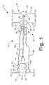
- the present invention uses an automatic inter-axle differential (IAD) locking system 10 for a vehicle 11 having a tandem drive axle assembly 15, as generally illustrated in Fig. 1.
- the vehicle 11 has an engine 12, which is drivingly connected to a transmission 14.
- a main drive shaft 16 extends longitudinally from the transmission 14 to the tandem drive axle assembly 15, and may be coupled at one end via a conventional coupling 17, such as a yoke or a universal joint, to the transmission 14, and at the other end by another conventional coupling 18 to an input shaft 30 of the tandem drive axle assembly 15.
- a conventional coupling 17 such as a yoke or a universal joint
- Vehicle 11 may be any vehicle having a tandem drive axle assembly, such as a truck, bus or other over-the-road vehicle which has a tandem drive axle assembly comprising two axially spaced axles.
- the tandem drive axle assembly 15 is usually located near the rear of a vehicle and may, therefore, be referred to herein as a tandem drive rear axle assembly.
- the tandem drive rear axle assembly 15 comprises a rearward rear axle 22, which in turn comprises axially aligned right and left axle shafts (not shown), which are driven through an axle differential 23.
- a forward rear axle 24 also comprises axially aligned right and left axle shafts (not shown), which are driven through an axle differential 25.
- the axles 22 and 24 of the tandem rear axle assembly 15 herein are axially spaced apart but are in proximity with each other toward the rear of the vehicle 11.
- axle differentials 23 and 25 (which are to be distinguished from an inter-axle differential to be subsequently described) may be conventional.
- a tandem inter-axle assembly 20 of the preferred embodiment has a housing 26 at its forward end to rotatably support the longitudinally extending input shaft 30, which may be axially aligned with the vehicle drive shaft 16.
- the forward end of input shaft 30 is coupled to vehicle main drive shaft 16 in direct drive relationship by means of the coupling 18.
- the input shaft 30 is received in the inter-axle differential 20 for transmitting input torque from the vehicle main drive shaft 16 to the inter-axle differential 20.
- an inter-axle output shaft 31 that transmits torque to the rearward rear axle 22 (via an output drive shaft 50 and a rearward coupling 62, as shown in Fig. 1), a rotating side helical gear speed sensor 27, and a rotating sliding clutch lock speed sensor 28.
- the sensors 27, 28 may be conventionally available sensors, for example, Dana Corporation part number 673425 or Wabash part number 9184.
- the vehide IAD 20 further comprises a clutch locking mechanism 32 that includes a rotating side helical gear 33 and a rotating sliding clutch 34.
- the sliding clutch lock mechanism 32 is engaged and subsequently locked, where locked is defined as helical gear teeth 33a and sliding clutch teeth 34a being in a meshing relationship.
- Helical gear teeth 33a are preferably in a fixed position.
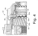
- Fig. 4 which is a partial, side view, cut-away of the cover 26 of the inter-axle differential 20 of Fig. 2, taken near to the sliding clutch sensor 28, illustrates the sliding clutch lock mechanism 32 being disengaged, where the helical gear teeth 33a of the rotating side helical gear 33 and the teeth 34a of the sliding clutch 34 are separated.
- Fig. 4 Also illustrated in Fig. 4 is the alignment of the sliding clutch speed sensor 28 over the teeth 34a of the sliding clutch 34.
- the sliding clutch speed sensor 28 measures a speed of the sliding clutch 34 by sensing a presence and then an absence of the rotating teeth 34a of the clutch 34 passing below the sliding clutch speed sensor 28.
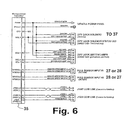
- the sliding clutch speed sensor 28 (via first electrical means 66 shown in Fig. 1) provides a sliding clutch signal to a microprocessor 35 (see Fig. 6, for example, Motorola MC9S12D64 or equivalent and POLE SENSOR INPUT #1/#2 in Fig. 6) for determining the speed of the sliding clutch 34, when the gear 33 and the clutch 34 are disengaged.
- the sensor 28 measures zero sliding clutch speed even though the sliding dutch 34 continues to rotate.
- the helical gear speed sensor 27, shown in Fig. 3, determines the speed of the helical gear 33 by sensing the presence and absence of second helical gear teeth 33b, which provides a helical gear signal to the microprocessor 35 (see POLE SENSOR INPUT #1/#2 in Fig. 6).
- the sliding clutch speed sensor 28 no longer senses the presence and then the absence of the teeth 34a. It is a discovery of the instant invention that when the clutch mechanism 32 is locked, the sliding clutch speed sensor 28 does not provide a signal to the microprocessor 35, even though the sliding clutch 34 continues to rotate, which is due to the specific placement of the clutch sensor 28. The absence of a signal is determined by the microprocessor 35 to mean that the clutch mechanism 32 is locked. Thus, the microprocessor 35 is informed of the locked or unlocked state (or mode) of the clutch mechanism 32, without requiring a separate sensor in addition to the two speed sensors 27, 28.
- a general overview of the IAD system 10 terminology and functions includes the following modes.
- auto lock mode no driver interaction is required and the system automatically detects slipping and locks, for example, for up to 15 seconds.
- manual lock mode the operator presses the lock switch (for example, see Fig. 6) in the vehicle cab and then the IAD 20 locks, for example, for 60 seconds.
- manual lock and hold mode the operator presses and holds the lock switch, for example, for 5 seconds, and then the IAD 20 remains locked until the unlock switch (see, for example, Fig. 6) is pressed or power to the IAD 20 is recycled.
- manual unlock and hold mode the operator presses and holds the unlock switch in, for example, for 5 seconds, and then the IAD 20 remains unlocked until the lock switch is pressed or power to the IAD 20 is recycled.
- Display lamp functions utilized within the IAD 20 are unlocked lamp solidly lit (IAD lock is disengaged), locked lamp flashing (IAD 20 is attempting to engage the IAD lock), locked lamp solidly lit (IAD 20 has been locked), locked lamp flashing quickly (IAD 20 is in manual lock and hold mode), and unlocked lamp flashing (IAD 20 is attempting to disengage the lock). Note that in the unlocked lamp flashing mode, if the unlocked lamp does not turn solid, which indicates lock disengagement, then the operator is instructed to remove pressure from the throttle momentarily to allow the lock to disengage.
- FIG. 5 there is shown a flow chart of logic in accordance with the present invention.
- the automatic IAD lock system 10 Upon start up or returning from an IAD disengagement mode, the automatic IAD lock system 10 is in an IAD unlocked mode where an engage solenoid 37 (as shown in Fig. 1) is turned off.
- the solenoid may be, for example, a KIP Incorporated part number 2P2108.
- an unlock lamp (see Fig. 6) is preferably turned on solidly in the vehicle compartment to indicate to the operator of the vehicle 11 that the clutch mechanism 32 is unlocked.
- a relock timer is set for a short delay that allows the sliding clutch speed to be established by the system 10 following disengagement that could be configured from milliseconds to seconds, where a preferred implementation would be approximately one second. Note that when the clutch mechanism 32 is engaged, there is no speed signal received from the sliding clutch teeth 34a because the teeth 34a are meshed with the helical teeth 33a, thus providing no gaps therebetween. Therefore, initially fallowing disengagement, the sensor 28 needs this short relock time period before beginning to sense the gaps between the gear teeth 33a, 34a, so as to prevent immediate re-engaging of the IAD clutch mechanism 32.
- the system 10 determines if the following conditions prevail: is the mathematical absolute difference between the sliding clutch 34 revolutions per minute and the side helical gear 33 revolutions per minute greater than a minimum limit (or has a manual lock request or has a manual lock and hold request been initiated), and is the mathematical absolute difference between the sliding clutch 34 revolutions per minute and the side helical gear 33 revolutions per minute less than a maximum limit, and is the speed of the vehicle less than a third limit, and has the relock timer expired, and has no manual unlock and hold been requested.
- the speed of the vehicle 11 may be obtained from the vehicle communication data link, for example, J1587 COMM LINK or J1939 COMM LINK (see Figs. 6 and 7), which follow the standards set by the Society of Automotive Engineers (SAE).
- SAE Society of Automotive Engineers
- the instant application is not limited by the first electrical means 66 and a second electrical means 69 (for example, wires, connectors, or cables, which could include any present or future SAE COMM LINKS), solenoid 37, the sensors 27, 28, the micorprocessor 35, or an engine electronic control unit (ECU) 29 (see Fig. 1), which electrically communicates with the microprocessor 35 via the second electrical means 69.
- ECU engine electronic control unit
- the system 10 causes the inter-axle differential clutch mechanism 32 to commence the IAD engage mode by setting an engage timer, by turning on the engage solenoid 37, and by causing the "lock" lamp to flash on and off.
- the engage timer could be configured to run from seconds to minutes, but a preferred implementation would be approximately fifteen seconds.
- the system 10 While in the IAD engage mode, the system 10 monitors the vehicle speed to determine if the vehicle speed is greater than the third limit and the system 10 monitors the engage timer to see if the engage timer has expired. If either of these two conditions are met then the system 10 places the IAD 20 into the disengaged mode that is described below.
- a further discovery of the present invention is that, optionally, when the IAD 20 is in the process of engaging, as discussed above, the system 10 may communicate a vehicle communication data link message (such as a signal to COMM LINK J1939 or the like) to the electronic controls 29 in the engine 12 to momentarily (for example, for a few milliseconds to approximately one second) break engine torque.
- a vehicle communication data link message such as a signal to COMM LINK J1939 or the like
- the amount of time that the engine torque is disrupted may not be a fixed amount of time. Instead, the amount of time that the engine torque is disrupted for engagement may vary depending upon the speed and/or an acceleration of the vehicle 11, or the mechanical performance of the sliding clutch 34, the helical gear 33, or other parts of the present invention.
- the system 10 monitors the sliding clutch RPM to see if it is approximately equal to zero (via the sliding clutch speed sensor 28, see, for example, Fig. 6 connections POLE SENSOR SPEED INPUT #1 A-B or #2 A-B). If the sliding clutch RPM is approximately equal to zero, then the system 10 places the IAD 20 into the locked mode via the engage solenoid 37 (see, for example, Fig. 6 connections DIFF LOCK SOLENOID A-B), solidly lights the lock lamp (see, for example, Fig. 6 connection DIFF LOCK SWITCH/LAMPS S10), and initiates a lock timer, which could be configured to run from seconds to minutes, but a preferred implementation would be approximately fifteen seconds.
- the system 10 While in the IAD locked mode, the system 10 monitors the vehicle speed to determine if the vehicle speed is greater than the third limit, or the system 10 monitors the lock timer to see if the lock timer has expired and that the operator has not requested the system 10 to be placed in a manual lock and hold mode, or the system monitors that the operator has not requested manual unlock mode. If any of these conditions has been met, then the system 10 places the IAD 20 into the disengaged mode, which includes turning off the engage solenoid 37, and causing the unlock lamp to flash on and off. Also, the relock timer, as mentioned above, is set for a short delay that allows the sliding clutch speed to be established by the system 10 following disengagement that could be configured from milliseconds to seconds, where a preferred implementation would be approximately one second.
- Fig. 1 schematically depicts the solenoid 37 adjacent the engine 12, where the solenoid 37 controls pressurized air flow through the port 38 (see Figs. 2 and 3).
- the air causes the inter-axle differential clutch mechanism 32, which may also include various other elements (such as, for example, a push rod 42, a piston 43, a shift cylinder 44, a shift fork 45, a selector switch 46 (used in a conventional manual control versus the microprocessor 35 control of the present invention), and a spring 47) to engage (Fig. 8) or disengage (Fig. 9).
- the air flow is controlled by the selector switch 46, but in the present invention the separate solenoid 37 may be utilized to allow pressurized air to enter or not to enter port 38, which subsequently causes the fork 45 to shift the sliding clutch 34.
- the system may choose to return to the engage mode. If the wheels do not slip, the system 10 will continue to monitor for any future slip. This procedure assures that the IAD 20 will not stay engaged for longer than necessary.
- the manual lock and hold request overrides the lock timer, which allows the system 10 to remain in the locked condition if the operator so chooses.
- Another discovery of the present invention is that, optionally, when the IAD 20 is in this process of disengaging, the system 10 may communicate a vehicle communication data link message to the electronic controls 29 in the engine 12 to momentarily (for example, for a few milliseconds to approximately one second) break engine torque. This discovery has been found to smooth the disengagement of the IAD 20.
- the amount of time that the engine torque is disrupted may not be a fixed amount of time. Instead, the amount of time that the engine torque is disrupted for disengagement may vary depending upon the speed and acceleration of the vehicle 11, the sliding clutch 34, the helical gear 33, or other parts of the present invention.
- the system 10 While in the IAD disengage mode, the system 10 monitors the sliding clutch RPM so as to determine if the sliding clutch 34 is greater than zero (i.e., the teeth 33a, 34a are no longer meshed). If the sliding clutch RPM is greater than zero, then the system 10 returns the IAD 20 to the unlocked mode, as discussed above, where the engage solenoid 37 remains off and the "unlock lamp" is turned on solid in the vehicle compartment to indicate to the operator of the vehicle 11 that the clutch mechanism 32 is unlocked. The relock timer is also initiated at this time.
- the microprocessor 35 is electrically connected to the sensors 27, 28 by the first electrical means 66, and the microprocessor 35 is electrically connected to the solenoid 37 by third electrical means 67. Although shown located within the engine 12, the microprocessor 35 could be located elsewhere.
- a source of compressed air 63 is pneumatically connected to the solenoid 37 by first pneumatic means 64, while the solenoid 37 would also be pneumatically connected by second pneumatic means 65 to the compressed air port 38, for controlling the engagement/disengagement of the clutch mechanism 32.
- the source of compressed air 63 could be a separate source or a part of the engine 12.
- Figs. 6 and 7 illustrate various embodiments of electrical connects between the microprocessor 35 the inputs and outputs (for example, 27, 28, 37 (via the first electrical means 66) and various conventional lamps/LEDs) for the system 10. It may be appreciated that the system 10 is not limited by the lamps, LEDs, solenoids, and/or the pneumatic means to cause air to flow to the shift fork 45 that causes engagement, disengagement, and locking of the locking mechanism 32.
Abstract
Description
- The present invention relates to an actuation enhancement for an automated vehicle inter-axle differential locking system.
- Tandem drive axle assemblies having a forward rear axle and a rearward rear axle in proximity with each other are well known. Such tandem drive assemblies are widely used on heavy duty trucks and other over-the-road vehicles, such as busses, which have a high vehicle weight and/or a high load carrying capacity. In such assemblies, both rear axles may be power driven.
- An inter-axle differential (IAD) is commonly employed in such vehicles to split the input shaft torque between the front and rear axle of the tandem. It is common for a vehicle operator to engage and disengage a lock out that overrides or disables the IAD through the use of a pneumatic switch, which typically is mounted on the vehicle dash. The pneumatic switch, in turn, applies air to an axle mounted actuator, which engages a sliding dog clutch to "lock" the inter-axle differential.
- However, there are several shortcomings to the above-described manual methods of engaging/disengaging the IAD. First, failure of the vehicle operator to notice that wheel end slip is occurring and then to engage the IAD, can result in spin out failures. Second, engagement of the IAD, while significant slipping is in process, can result in damage to either or both of the drive axles. Third, leaving the IAD engaged for an extended length of time can result in "drive line wind-up" and a resulting inability to disengage the IAD without reversing the vehicle. Fourth, since the actuation of the engagement and disengagement of the IAD are typically switched on or switched off by the operator, the IAD does not smoothly transition from one mode to the other. As a result of these shortcomings, extended wear can occur and the operator may not notice the wear, as actual, engagement and disengagement of the IAD is not typically indicated to the operator.
- More recently, automatic differential lockout mechanisms have come into use that attempt to minimize wear from engaging or disengaging of the differentials. U.S. Patent No. 4,671,373 to Sigl discloses a locking-type differential being automatically prevented from engaging upon certain vehicle operating conditions. For example, if the steering wheel is deflected or transverse acceleration is sensed, the differential will not be allowed to be locked. The differential is likewise unlocked or prevented from locking if, for example, the brakes are applied or the engine is operating under an idle condition. On the other hand, for example, if a kick-down signal from the accelerator is sensed, or if the difference in speed of driven and rolling wheels exceeds a predetermined amount, the differential is controlled to lock.
- U.S. Patent No. 5,071,392 to Stall et al. discloses a process of continuously controlling the degree of locking of open differential drives in a driven axle of a multi-axle vehicle where the differential speed of the driven wheels is compared to the vehicle speed of the non-driven wheels.
- U.S. Patent No. 5,130,928 to Petersen provides an anti-lock and/or anti-slip apparatus for commercial type vehicles where an electronic system determines whether the rotational speed of the cardan shaft varies from the average speed of the monitored wheels. Upon receipt of a variance, the electronic system controls the locking of a longitudinal differential.
- U.S. Patent No. 5,989,147 to Forrest et al. discloses an electronically controllable differential which transfers a predetermined amount of torque through a rotatable differential based upon, in part, a predetermined rotational condition of the side gear.
- U.S. Patent No. 6,174,255 to Porter et al. teaches a differential lock control system that employs speed sensors and an articulation angle sensor that communicate speed signals and an articulation angle signal to a microprocessor for controlling the locks on front and rear differentials for an articulated work vehicle. In an automatic mode, the microprocessor controls the locking of the differentials by comparing predicted axle speeds to actual speeds received from the speed sensors and an articulation angle from the articulation sensor.
- U.S. Patent No. 6,487,486 to Anderson discloses a process for continuously controlling the transfer of torque within a differential while utilizing control logic methodology. Changes in torque values are determined from output shafts speeds and vehicle speeds.
- U.S. Patent No. 6,579,204 to Brown et al. generally discloses a full-time power transfer system for controlling speed differentiation and torque biasing across an interaxle differential in response to changes in sensors that monitor dynamic and operational characteristics of the vehicle.
- Even with the above-described current automatic means for controlling the engagement and disengagment of the inter-axle differential, optimization of conditions, for example, minimizing damage and excessive wear of IAD components, improving the engagement/disengagement timing of the inter-axle differential locking mechanism, and enhancing the actuation of the engagement/disengagement, can still be made.
- The present invention relates to an actuation enhancement for a vehicle inter-axle differential (IAD) locking system that is used in a vehicle having an engine and a tandem drive axle. The automated IAD lock system comprises a single inter-axle differential having a clutch locking mechanism, the clutch locking mechanism being capable of an engagement mode and a disengagement mode, and at least one microprocessor. When the clutch locking mechanism is placed in the engagement mode or placed in the disengagement mode, the microprocessor momentarily communicates a data link message to an engine electronic control unit (ECU) so as to break engine torque, thus facilitating engagement or disengagement of the clutch locking mechanism.
- Further advantages of the present invention will be apparent from the following description and appended claims, reference being made to the accompanying drawings forming a part of a specification, wherein like reference characters designate corresponding parts of several views.
-
- Fig. 1 is a mechanical schematic of a top-plan view of a vehicle in accordance with the present invention;
- Fig. 2 is a three dimensional view of an inter-axle differential in accordance with the present invention;
- Fig. 3 is a partial cut-away of the three dimensional view of the inter-axle differential of Fig. 2;
- Fig. 4 is a partial cut-away of a three dimensional side view of the inter-axle differential of Fig. 2;
- Fig. 5 is a flow chart of the logic in accordance with the present invention;
- Fig. 6 is an electrical connector diagram in accordance with the present invention;
- Fig. 7 is an electrical schematic of a microprocessor in accordance with the present invention;
- Fig. 8 is a side view of an engaged inter-axle differential in accordance with the present invention; and
- Fig. 9 is a side view of a disengaged inter-axle differential in accordance with the present invention.
- It is to be understood that the invention may assume various alternative orientations and step sequences, except where expressly specified to the contrary. It is also to be understood that the specific devices and processes illustrated in the attached drawings, and described in the following specification are simply exemplary embodiments of the inventive concepts defined in the appended claims. Hence, specific dimensions, directions or other physical characteristics relating to the embodiments disclosed are not to be considered as limiting, unless the claims expressly state otherwise.
- Preferably, the present invention uses an automatic inter-axle differential (IAD)
locking system 10 for avehicle 11 having a tandemdrive axle assembly 15, as generally illustrated in Fig. 1. Thevehicle 11 has anengine 12, which is drivingly connected to atransmission 14. Amain drive shaft 16 extends longitudinally from thetransmission 14 to the tandemdrive axle assembly 15, and may be coupled at one end via aconventional coupling 17, such as a yoke or a universal joint, to thetransmission 14, and at the other end by anotherconventional coupling 18 to aninput shaft 30 of the tandemdrive axle assembly 15. -
Vehicle 11 may be any vehicle having a tandem drive axle assembly, such as a truck, bus or other over-the-road vehicle which has a tandem drive axle assembly comprising two axially spaced axles. The tandemdrive axle assembly 15 is usually located near the rear of a vehicle and may, therefore, be referred to herein as a tandem drive rear axle assembly. The tandem driverear axle assembly 15 comprises a rearwardrear axle 22, which in turn comprises axially aligned right and left axle shafts (not shown), which are driven through anaxle differential 23. In addition, a forwardrear axle 24 also comprises axially aligned right and left axle shafts (not shown), which are driven through anaxle differential 25. Theaxles rear axle assembly 15 herein are axially spaced apart but are in proximity with each other toward the rear of thevehicle 11. - All parts of both the
vehicle 11 as a whole and the tandem driverear axle assembly 15 described so far may be conventional. Thus, the twoaxle differentials 23 and 25 (which are to be distinguished from an inter-axle differential to be subsequently described) may be conventional. - Turning to Fig. 2, a tandem inter-axle
assembly 20 of the preferred embodiment has ahousing 26 at its forward end to rotatably support the longitudinally extendinginput shaft 30, which may be axially aligned with thevehicle drive shaft 16. The forward end ofinput shaft 30 is coupled to vehiclemain drive shaft 16 in direct drive relationship by means of thecoupling 18. Theinput shaft 30 is received in theinter-axle differential 20 for transmitting input torque from the vehiclemain drive shaft 16 to theinter-axle differential 20. Also shown in Fig. 2 are aninter-axle output shaft 31 that transmits torque to the rearward rear axle 22 (via anoutput drive shaft 50 and arearward coupling 62, as shown in Fig. 1), a rotating side helicalgear speed sensor 27, and a rotating sliding clutchlock speed sensor 28. Thesensors - As illustrated in Fig. 3, the
vehide IAD 20 further comprises aclutch locking mechanism 32 that includes a rotating sidehelical gear 33 and a rotating slidingclutch 34. As shown in Fig. 3, the slidingclutch lock mechanism 32 is engaged and subsequently locked, where locked is defined ashelical gear teeth 33a and slidingclutch teeth 34a being in a meshing relationship.Helical gear teeth 33a are preferably in a fixed position. - On the other hand, Fig. 4, which is a partial, side view, cut-away of the
cover 26 of the inter-axle differential 20 of Fig. 2, taken near to the slidingclutch sensor 28, illustrates the slidingclutch lock mechanism 32 being disengaged, where thehelical gear teeth 33a of the rotating sidehelical gear 33 and theteeth 34a of the slidingclutch 34 are separated. - Also illustrated in Fig. 4 is the alignment of the sliding
clutch speed sensor 28 over theteeth 34a of the slidingclutch 34. When the slidingclutch lock mechanism 32 is disengaged, the slidingclutch speed sensor 28 measures a speed of the slidingclutch 34 by sensing a presence and then an absence of therotating teeth 34a of the clutch 34 passing below the slidingclutch speed sensor 28. Thus, the sliding clutch speed sensor 28 (via firstelectrical means 66 shown in Fig. 1) provides a sliding clutch signal to a microprocessor 35 (see Fig. 6, for example, Motorola MC9S12D64 or equivalent and POLESENSOR INPUT # 1/#2 in Fig. 6) for determining the speed of the slidingclutch 34, when thegear 33 and the clutch 34 are disengaged. However, when theclutch mechanism 32 is fully engaged (as in Fig. 3), thesensor 28 measures zero sliding clutch speed even though the sliding dutch 34 continues to rotate. - The helical
gear speed sensor 27, shown in Fig. 3, determines the speed of thehelical gear 33 by sensing the presence and absence of secondhelical gear teeth 33b, which provides a helical gear signal to the microprocessor 35 (see POLESENSOR INPUT # 1/#2 in Fig. 6). - When the
gear 33 and the clutch 34 are locked, the slidingclutch speed sensor 28 no longer senses the presence and then the absence of theteeth 34a. It is a discovery of the instant invention that when theclutch mechanism 32 is locked, the slidingclutch speed sensor 28 does not provide a signal to themicroprocessor 35, even though the slidingclutch 34 continues to rotate, which is due to the specific placement of theclutch sensor 28. The absence of a signal is determined by themicroprocessor 35 to mean that theclutch mechanism 32 is locked. Thus, themicroprocessor 35 is informed of the locked or unlocked state (or mode) of theclutch mechanism 32, without requiring a separate sensor in addition to the twospeed sensors - A general overview of the
IAD system 10 terminology and functions includes the following modes. In auto lock mode, no driver interaction is required and the system automatically detects slipping and locks, for example, for up to 15 seconds. In manual lock mode, the operator presses the lock switch (for example, see Fig. 6) in the vehicle cab and then theIAD 20 locks, for example, for 60 seconds. In manual lock and hold mode, the operator presses and holds the lock switch, for example, for 5 seconds, and then theIAD 20 remains locked until the unlock switch (see, for example, Fig. 6) is pressed or power to theIAD 20 is recycled. In manual unlock and hold mode the operator presses and holds the unlock switch in, for example, for 5 seconds, and then theIAD 20 remains unlocked until the lock switch is pressed or power to theIAD 20 is recycled. - Display lamp functions utilized within the
IAD 20 are unlocked lamp solidly lit (IAD lock is disengaged), locked lamp flashing (IAD 20 is attempting to engage the IAD lock), locked lamp solidly lit (IAD 20 has been locked), locked lamp flashing quickly (IAD 20 is in manual lock and hold mode), and unlocked lamp flashing (IAD 20 is attempting to disengage the lock). Note that in the unlocked lamp flashing mode, if the unlocked lamp does not turn solid, which indicates lock disengagement, then the operator is instructed to remove pressure from the throttle momentarily to allow the lock to disengage. - Referring to Fig. 5, there is shown a flow chart of logic in accordance with the present invention. Upon start up or returning from an IAD disengagement mode, the automatic
IAD lock system 10 is in an IAD unlocked mode where an engage solenoid 37 (as shown in Fig. 1) is turned off. The solenoid may be, for example, a KIP Incorporated part number 2P2108. Also, an unlock lamp (see Fig. 6) is preferably turned on solidly in the vehicle compartment to indicate to the operator of thevehicle 11 that theclutch mechanism 32 is unlocked. - In addition, a relock timer is set for a short delay that allows the sliding clutch speed to be established by the
system 10 following disengagement that could be configured from milliseconds to seconds, where a preferred implementation would be approximately one second. Note that when theclutch mechanism 32 is engaged, there is no speed signal received from the slidingclutch teeth 34a because theteeth 34a are meshed with thehelical teeth 33a, thus providing no gaps therebetween. Therefore, initially fallowing disengagement, thesensor 28 needs this short relock time period before beginning to sense the gaps between thegear teeth clutch mechanism 32. - To change from the IAD unlocked mode to the IAD engaged mode the
system 10, through the aid of themicroprocessor 35, determines if the following conditions prevail: is the mathematical absolute difference between the sliding clutch 34 revolutions per minute and the sidehelical gear 33 revolutions per minute greater than a minimum limit (or has a manual lock request or has a manual lock and hold request been initiated), and is the mathematical absolute difference between the sliding clutch 34 revolutions per minute and the sidehelical gear 33 revolutions per minute less than a maximum limit, and is the speed of the vehicle less than a third limit, and has the relock timer expired, and has no manual unlock and hold been requested. - It can be appreciated by one skilled in the art that the speed of the
vehicle 11 may be obtained from the vehicle communication data link, for example, J1587 COMM LINK or J1939 COMM LINK (see Figs. 6 and 7), which follow the standards set by the Society of Automotive Engineers (SAE). It can further be appreciated that the instant application is not limited by the firstelectrical means 66 and a second electrical means 69 (for example, wires, connectors, or cables, which could include any present or future SAE COMM LINKS),solenoid 37, thesensors micorprocessor 35, or an engine electronic control unit (ECU) 29 (see Fig. 1), which electrically communicates with themicroprocessor 35 via the secondelectrical means 69. - If, however, the above conditions are met, then the
system 10 causes the inter-axle differentialclutch mechanism 32 to commence the IAD engage mode by setting an engage timer, by turning on the engagesolenoid 37, and by causing the "lock" lamp to flash on and off. The engage timer could be configured to run from seconds to minutes, but a preferred implementation would be approximately fifteen seconds. - While in the IAD engage mode, the
system 10 monitors the vehicle speed to determine if the vehicle speed is greater than the third limit and thesystem 10 monitors the engage timer to see if the engage timer has expired. If either of these two conditions are met then thesystem 10 places theIAD 20 into the disengaged mode that is described below. - A further discovery of the present invention is that, optionally, when the
IAD 20 is in the process of engaging, as discussed above, thesystem 10 may communicate a vehicle communication data link message (such as a signal to COMM LINK J1939 or the like) to theelectronic controls 29 in theengine 12 to momentarily (for example, for a few milliseconds to approximately one second) break engine torque. This discovery has been found to smooth the engagement of theIAD 20. - Although not wishing to be bound by any theory, it is believed that this smooth engagement results from reducing the speed differential and torque between the
teeth teeth teeth gears teeth gear 33 and clutch 34. - Note that the amount of time that the engine torque is disrupted may not be a fixed amount of time. Instead, the amount of time that the engine torque is disrupted for engagement may vary depending upon the speed and/or an acceleration of the
vehicle 11, or the mechanical performance of the slidingclutch 34, thehelical gear 33, or other parts of the present invention. - Otherwise, following IAD engagement, the
system 10 monitors the sliding clutch RPM to see if it is approximately equal to zero (via the slidingclutch speed sensor 28, see, for example, Fig. 6 connections POLE SENSORSPEED INPUT # 1 A-B or #2 A-B). If the sliding clutch RPM is approximately equal to zero, then thesystem 10 places theIAD 20 into the locked mode via the engage solenoid 37 (see, for example, Fig. 6 connections DIFF LOCK SOLENOID A-B), solidly lights the lock lamp (see, for example, Fig. 6 connection DIFF LOCK SWITCH/LAMPS S10), and initiates a lock timer, which could be configured to run from seconds to minutes, but a preferred implementation would be approximately fifteen seconds. - While in the IAD locked mode, the
system 10 monitors the vehicle speed to determine if the vehicle speed is greater than the third limit, or thesystem 10 monitors the lock timer to see if the lock timer has expired and that the operator has not requested thesystem 10 to be placed in a manual lock and hold mode, or the system monitors that the operator has not requested manual unlock mode. If any of these conditions has been met, then thesystem 10 places theIAD 20 into the disengaged mode, which includes turning off the engagesolenoid 37, and causing the unlock lamp to flash on and off. Also, the relock timer, as mentioned above, is set for a short delay that allows the sliding clutch speed to be established by thesystem 10 following disengagement that could be configured from milliseconds to seconds, where a preferred implementation would be approximately one second. - Note that the engage
solenoid 37 may be disposed anywhere in/on the vehicle where it will not be damaged. By way of example only, Fig. 1 schematically depicts thesolenoid 37 adjacent theengine 12, where thesolenoid 37 controls pressurized air flow through the port 38 (see Figs. 2 and 3). - As conventionally shown in Figs. 8 and 9, the air causes the inter-axle differential
clutch mechanism 32, which may also include various other elements (such as, for example, apush rod 42, apiston 43, ashift cylinder 44, ashift fork 45, a selector switch 46 (used in a conventional manual control versus themicroprocessor 35 control of the present invention), and a spring 47) to engage (Fig. 8) or disengage (Fig. 9). In these illustrations, the air flow is controlled by theselector switch 46, but in the present invention theseparate solenoid 37 may be utilized to allow pressurized air to enter or not to enterport 38, which subsequently causes thefork 45 to shift the slidingclutch 34. - Note, however, that it is within the scope and spirit of the present invention that if road conditions result in wheel slip, the system may choose to return to the engage mode. If the wheels do not slip, the
system 10 will continue to monitor for any future slip. This procedure assures that theIAD 20 will not stay engaged for longer than necessary. In addition, the manual lock and hold request overrides the lock timer, which allows thesystem 10 to remain in the locked condition if the operator so chooses. - Another discovery of the present invention is that, optionally, when the
IAD 20 is in this process of disengaging, thesystem 10 may communicate a vehicle communication data link message to theelectronic controls 29 in theengine 12 to momentarily (for example, for a few milliseconds to approximately one second) break engine torque. This discovery has been found to smooth the disengagement of theIAD 20. - Although not wishing to be bound by any theory, it is believed that this smooth disengagement results from reducing the torque between the
teeth - It should be appreciated that the amount of time that the engine torque is disrupted may not be a fixed amount of time. Instead, the amount of time that the engine torque is disrupted for disengagement may vary depending upon the speed and acceleration of the
vehicle 11, the slidingclutch 34, thehelical gear 33, or other parts of the present invention. - While in the IAD disengage mode, the
system 10 monitors the sliding clutch RPM so as to determine if the slidingclutch 34 is greater than zero (i.e., theteeth system 10 returns theIAD 20 to the unlocked mode, as discussed above, where the engagesolenoid 37 remains off and the "unlock lamp" is turned on solid in the vehicle compartment to indicate to the operator of thevehicle 11 that theclutch mechanism 32 is unlocked. The relock timer is also initiated at this time. - Returning to Fig. 1, there is illustrated the interconnection of various electrical and pneumatic parts that are described above. The
microprocessor 35 is electrically connected to thesensors electrical means 66, and themicroprocessor 35 is electrically connected to thesolenoid 37 by thirdelectrical means 67. Although shown located within theengine 12, themicroprocessor 35 could be located elsewhere. A source ofcompressed air 63 is pneumatically connected to thesolenoid 37 by first pneumatic means 64, while thesolenoid 37 would also be pneumatically connected by second pneumatic means 65 to thecompressed air port 38, for controlling the engagement/disengagement of theclutch mechanism 32. The source ofcompressed air 63 could be a separate source or a part of theengine 12. - Figs. 6 and 7 illustrate various embodiments of electrical connects between the
microprocessor 35 the inputs and outputs (for example, 27, 28, 37 (via the first electrical means 66) and various conventional lamps/LEDs) for thesystem 10. It may be appreciated that thesystem 10 is not limited by the lamps, LEDs, solenoids, and/or the pneumatic means to cause air to flow to theshift fork 45 that causes engagement, disengagement, and locking of thelocking mechanism 32. - - In accordance with the provisions of the patent statutes, the principles and modes of operation of this invention have been described and illustrated in its preferred embodiments. However, it must be understood that the invention may be practiced otherwise than specifically explained and illustrated without departing from its spirit or scope.
Claims (12)
- An inter-axle differential locking system for a vehicle having an engine and a tandem drive axle, comprising:a single inter-axle differential having a clutch locking mechanism, said clutch locking mechanism being capable of an engagement mode and a disengagement mode; andat least one microprocessor;wherein when said clutch locking mechanism is placed in said engagement mode or placed in said disengagement mode, said microprocessor momentarily communicates a data link message to an engine electronic control unit to break engine torque to facilitate an engagement or a disengagement of said clutch locking mechanism.
- The inter-axle differential locking system of claim 1, wherein said clutch mechanism includes a rotating side helical gear that has helical gear teeth and a rotating sliding clutch that has sliding clutch teeth, and when said clutch mechanism is placed in said engagement mode, said engine torque is disrupted for an amount of time in a range of a few milliseconds to approximately one second, thus reducing the speed differential and torque between said helical gear teeth and said sliding clutch teeth.
- The inter-axle differential locking system of claim 1, wherein said clutch mechanism includes a rotating side helical gear that has helical gear teeth and a rotating sliding clutch that has sliding clutch teeth, and when said dutch mechanism is placed in said disengagement mode, said engine torque is disrupted for an amount of time in a range of a few milliseconds to approximately one second, thus reducing the torque between said helical gear teeth and said sliding clutch teeth.
- The inter-axle differential locking system of claim 1, wherein an amount of time that said engine torque is disrupted is dependent upon the speed and/or acceleration of said vehicle and/or said clutch locking mechanism.
- The inter-axle differential locking system of claim 1, further comprising a solenoid, which is in communication with said microprocessor for controlling said engagement or said disengagement of said inter-axle differential.
- The inter-axle differential locking system of claim 1, wherein said inter-axle differential further comprises a pneumatic port, a shift fork, a push rod, a piston, and a shift cylinder.
- An inter-axle differential locking system for a vehicle having an engine and a tandem drive axle, comprising:an inter-axle differential of a vehicle having a rotating sliding clutch and a rotating side helical gear, said sliding clutch and said helical gear being capable of an engagement mode and a disengagement mode;a microprocessor; andan electrical connection between said microprocessor and an engine electronic control;wherein when said sliding clutch and said helical gear are placed in said engagement mode or placed in said disengagement mode, said microprocessor momentarily communicates a communication data link message over said electrical connection to said engine electronic control unit to break engine torque, in order to facilitate engagement or disengagement of said sliding clutch and said helical gear.
- The inter-axle differential locking system of claim 7, wherein said side helical gear has helical gear teeth and said sliding clutch has sliding clutch teeth, and when said side helical gear and said sliding clutch are placed in said engagement mode, said engine torque is disrupted for an amount of time in a range of a few milliseconds to approximately one second, thus reducing the speed differential and torque between said helical gear teeth and said sliding clutch teeth.
- The inter-axle differential locking system of claim 7, wherein said side helical gear has helical gear teeth and said sliding clutch has sliding clutch teeth, and when said side helical gear and said sliding clutch are placed in said disengagement mode, said engine torque is disrupted for an amount of time in a range of a few milliseconds to approximately one second, thus reducing the torque between said helical gear teeth and said sliding clutch teeth.
- The inter-axle differential locking system of claim 7, wherein an amount of time that said engine torque is disrupted is dependent upon the speed and/or acceleration of said vehicle, and/or said sliding clutch, and/or said helical gear.
- An inter-axle differential lock actuation enhancement method for an automated inter-axle differential locking system for a vehicle having a tandem drive axle, comprising:providing a single inter-axle differential having a clutch locking mechanism for a vehicle, said clutch locking mechanism being capable of an engagement mode and a disengagement mode;providing at least one microprocessor;placing said clutch locking mechanism in said engagement mode or placing said clutch locking mechanism in said disengagement mode; andmomentarily communicating a data link message to an engine electronic control unit to break engine torque, thus facilitating said engagement or said disengagement of said clutch locking mechanism.
- The inter-axle differential lock actuation enhancement method of claim 11, further comprising providing a signal within an operator's compartment of said vehicle that said inter-axle differential is engaged or disengaged.
Applications Claiming Priority (1)
| Application Number | Priority Date | Filing Date | Title |
|---|---|---|---|
| US11/050,122 US7195579B2 (en) | 2005-02-03 | 2005-02-03 | Automated inter-axle differential locking system actuation enhancement |
Publications (1)
| Publication Number | Publication Date |
|---|---|
| EP1688334A1 true EP1688334A1 (en) | 2006-08-09 |
Family
ID=36123357
Family Applications (1)
| Application Number | Title | Priority Date | Filing Date |
|---|---|---|---|
| EP06100946A Withdrawn EP1688334A1 (en) | 2005-02-03 | 2006-01-27 | Automated inter-axle differential locking system |
Country Status (6)
| Country | Link |
|---|---|
| US (1) | US7195579B2 (en) |
| EP (1) | EP1688334A1 (en) |
| KR (1) | KR20060089168A (en) |
| CN (1) | CN1821624A (en) |
| CA (1) | CA2534595A1 (en) |
| MX (1) | MXPA06001337A (en) |
Cited By (2)
| Publication number | Priority date | Publication date | Assignee | Title |
|---|---|---|---|---|
| EP2705966A3 (en) * | 2012-09-05 | 2017-12-13 | Jtekt Corporation | Vehicle drive apparatus |
| EP3309427A3 (en) * | 2016-08-22 | 2018-07-11 | Dana Heavy Vehicle Systems Group, LLC | Automated differential locking system |
Families Citing this family (19)
| Publication number | Priority date | Publication date | Assignee | Title |
|---|---|---|---|---|
| US7729839B2 (en) * | 2006-10-06 | 2010-06-01 | Dana Heavy Vehicle Systems Group, Llc | Automated inter-axle differential lock sensor configuration and calibration method |
| US7770681B2 (en) * | 2007-04-11 | 2010-08-10 | Caterpillar Inc | Traction control method in machine using lockable differential |
| CN102131670A (en) * | 2008-08-29 | 2011-07-20 | 沃尔沃建筑设备公司 | Frame-steered vehicle and a method for controlling a frame-steered vehicle |
| US9086104B2 (en) | 2008-12-22 | 2015-07-21 | Caterpillar Inc. | System and method for controlling wheel spin and wheel slip on a machine having differentially driven wheels |
| US9296295B2 (en) | 2008-12-22 | 2016-03-29 | Caterpillar Inc. | Machine control system utilizing inertial yaw sensor |
| US9126480B2 (en) | 2008-12-22 | 2015-09-08 | Caterpillar Inc. | Machine control system utilizing inertial yaw sensor |
| US8771140B2 (en) | 2008-12-22 | 2014-07-08 | Caterpillar Inc. | Machine control system utilizing inertial yaw sensor |
| US8109853B2 (en) | 2009-04-07 | 2012-02-07 | Ford Global Technologies, Llc | Control of a locking differential |
| MX366191B (en) | 2010-07-20 | 2019-07-01 | Dana Heavy Vehicle Sys Group | Drive axle system having a clutching device. |
| US8523738B2 (en) * | 2011-01-21 | 2013-09-03 | Dana Heavy Vehicle Systems Group, Llc | Method of shifting a tandem drive axle having an inter-axle differential |
| EP2928718B1 (en) * | 2012-12-05 | 2020-08-19 | Mack Trucks, Inc. | Vehicle with multiple drive axle assembly with a raisable and lowerable rear drive axle, and method of neutralizing the rear drive axle and operating such a vehicle |
| US9333857B2 (en) * | 2013-03-13 | 2016-05-10 | Dana Heavy Vehicle Systems Group, Llc | Multi-mode tandem axle function selection apparatus and method |
| JP6241592B2 (en) | 2013-05-17 | 2017-12-06 | スズキ株式会社 | Vehicle driving force distribution control device |
| US9656545B2 (en) | 2013-09-10 | 2017-05-23 | Schaeffler Technologies AG & Co. KG | Tandem axle disconnect with synchronized overdrive |
| US9440656B2 (en) * | 2014-12-03 | 2016-09-13 | Caterpillar Inc. | Torque control for dog clutch differential engagement |
| DE102015218995A1 (en) * | 2015-10-01 | 2017-04-06 | Zf Friedrichshafen Ag | Method for actuating a differential lock of a differential in a motor vehicle drive train |
| KR101718316B1 (en) * | 2015-12-11 | 2017-03-21 | 한국생산기술연구원 | Apparatus for locking differential having dual hydraulic cylinders |
| CN112469581B (en) * | 2018-07-20 | 2024-04-05 | 美国轮轴制造公司 | Open stabilizer bar assembly with backlash reduced disconnect mechanism |
| US11808342B2 (en) | 2022-02-08 | 2023-11-07 | Dana Automotive Systems Group, Llc | Differential carrier |
Citations (7)
| Publication number | Priority date | Publication date | Assignee | Title |
|---|---|---|---|---|
| GB1468489A (en) * | 1974-07-30 | 1977-03-30 | Eaton Corp | Axle assemblies |
| US4046210A (en) * | 1975-05-22 | 1977-09-06 | Eaton Corporation | Multiple drive axle assembly |
| US5130928A (en) * | 1988-10-21 | 1992-07-14 | Wabco Westinghouse Fahrzeugbremsen Gmbh | Anti-lock and/or anti-slip apparatus for commercial-type vehicles |
| WO1993001065A1 (en) * | 1991-07-01 | 1993-01-21 | Saab-Scania Aktiebolag | Arrangement for controlling the differential lock in a motor vehicle |
| US5860889A (en) * | 1995-12-01 | 1999-01-19 | Dana Corporation | Tandem forward rear axle lockout |
| EP1352771A2 (en) * | 2002-04-09 | 2003-10-15 | Dana Corporation | Tandem axle power divider assembly with inboard slip driveshaft connection |
| EP1468860A2 (en) * | 2003-04-16 | 2004-10-20 | Zf Friedrichshafen Ag | Control method and apparatus for shifting means for axle coupling and differential locking |
Family Cites Families (21)
| Publication number | Priority date | Publication date | Assignee | Title |
|---|---|---|---|---|
| US2603108A (en) * | 1950-06-05 | 1952-07-15 | Eaton Mfg Co | Multiple axle drive |
| US4050534A (en) * | 1975-02-13 | 1977-09-27 | Eaton Corporation | Drive axle system useable in 6 × 6 vehicle |
| DE3342574A1 (en) * | 1983-11-25 | 1985-06-05 | Robert Bosch Gmbh, 7000 Stuttgart | VEHICLE WITH A DETACHABLE LOCK FOR THE DRIVED WHEELS |
| US4937750A (en) * | 1987-12-23 | 1990-06-26 | Dana Corporation | Electronic control for vehicle four wheel drive system |
| US5247443A (en) | 1987-12-23 | 1993-09-21 | Dana Corporation | Electronic control for vehicle four wheel drive system |
| DE3837862C2 (en) * | 1988-11-08 | 1993-09-30 | Gkn Automotive Ag | Device for controlling limited slip differentials |
| JP2860340B2 (en) * | 1989-08-31 | 1999-02-24 | 富士重工業株式会社 | Left and right wheel torque distribution control device |
| KR940001977B1 (en) * | 1990-12-31 | 1994-03-12 | 삼성전자 주식회사 | Method for memorizing fine tuning data for tv receiver |
| US5259476A (en) * | 1991-04-26 | 1993-11-09 | Fuji Jukogyo Kabushiki Kaisha | Torque distribution control system for a four-wheel drive motor vehicle |
| DE4138738C1 (en) * | 1991-11-26 | 1993-01-21 | Mercedes-Benz Aktiengesellschaft, 7000 Stuttgart, De | Planetary gear drive for vehicle - includes automatic locking preventer mechanism |
| DE4202026A1 (en) * | 1992-01-25 | 1993-07-29 | Deere & Co | DRIVE ARRANGEMENT FOR CONTROLLING AND DISTRIBUTING THE DRIVE FOR A VEHICLE |
| DE4427040C2 (en) * | 1994-07-29 | 1998-05-20 | Steyr Daimler Puch Ag | Method for controlling a locking clutch acting as a differential lock |
| US5545103A (en) * | 1994-08-01 | 1996-08-13 | Dana Corporation | Vehicle transfer case with dual electrically-actuated magnetic clutches |
| US5927422A (en) * | 1997-06-12 | 1999-07-27 | Meritor Heavy Vehicle Systems, L L C | Method and apparatus for correcting drive wheel slip |
| US5989147A (en) * | 1998-02-25 | 1999-11-23 | Auburn Gear, Inc. | Electronically controllable limited slip differential |
| US6579204B2 (en) * | 1999-03-09 | 2003-06-17 | New Venture Gear, Inc. | Synchronized two-speed transfer case with lockable limited slip differential |
| JP2000326742A (en) * | 1999-05-20 | 2000-11-28 | Komatsu Ltd | Front/rear wheel load sharing control device of connecting vehicle |
| US6174255B1 (en) * | 1999-10-05 | 2001-01-16 | Deere & Company | Differential lock control system for articulated work vehicle |
| JP2001277896A (en) * | 2000-03-29 | 2001-10-10 | Komatsu Ltd | Interaxle differential device, and control method thereof |
| AT4837U1 (en) * | 2000-09-27 | 2001-12-27 | Steyr Powertrain Ag & Co Kg | DRIVE SYSTEM FOR AN ALL-WHEEL DRIVE MOTOR VEHICLE |
| US6487486B1 (en) * | 2001-08-14 | 2002-11-26 | Daimlerchrysler Corporation | Automatic differential control logic |
-
2005
- 2005-02-03 US US11/050,122 patent/US7195579B2/en active Active
-
2006
- 2006-01-27 CN CNA2006100066451A patent/CN1821624A/en active Pending
- 2006-01-27 EP EP06100946A patent/EP1688334A1/en not_active Withdrawn
- 2006-01-30 CA CA002534595A patent/CA2534595A1/en not_active Abandoned
- 2006-01-31 MX MXPA06001337A patent/MXPA06001337A/en active IP Right Grant
- 2006-02-03 KR KR1020060010659A patent/KR20060089168A/en not_active Application Discontinuation
Patent Citations (7)
| Publication number | Priority date | Publication date | Assignee | Title |
|---|---|---|---|---|
| GB1468489A (en) * | 1974-07-30 | 1977-03-30 | Eaton Corp | Axle assemblies |
| US4046210A (en) * | 1975-05-22 | 1977-09-06 | Eaton Corporation | Multiple drive axle assembly |
| US5130928A (en) * | 1988-10-21 | 1992-07-14 | Wabco Westinghouse Fahrzeugbremsen Gmbh | Anti-lock and/or anti-slip apparatus for commercial-type vehicles |
| WO1993001065A1 (en) * | 1991-07-01 | 1993-01-21 | Saab-Scania Aktiebolag | Arrangement for controlling the differential lock in a motor vehicle |
| US5860889A (en) * | 1995-12-01 | 1999-01-19 | Dana Corporation | Tandem forward rear axle lockout |
| EP1352771A2 (en) * | 2002-04-09 | 2003-10-15 | Dana Corporation | Tandem axle power divider assembly with inboard slip driveshaft connection |
| EP1468860A2 (en) * | 2003-04-16 | 2004-10-20 | Zf Friedrichshafen Ag | Control method and apparatus for shifting means for axle coupling and differential locking |
Cited By (2)
| Publication number | Priority date | Publication date | Assignee | Title |
|---|---|---|---|---|
| EP2705966A3 (en) * | 2012-09-05 | 2017-12-13 | Jtekt Corporation | Vehicle drive apparatus |
| EP3309427A3 (en) * | 2016-08-22 | 2018-07-11 | Dana Heavy Vehicle Systems Group, LLC | Automated differential locking system |
Also Published As
| Publication number | Publication date |
|---|---|
| US20060172852A1 (en) | 2006-08-03 |
| MXPA06001337A (en) | 2006-09-26 |
| KR20060089168A (en) | 2006-08-08 |
| US7195579B2 (en) | 2007-03-27 |
| CA2534595A1 (en) | 2006-08-03 |
| CN1821624A (en) | 2006-08-23 |
Similar Documents
| Publication | Publication Date | Title |
|---|---|---|
| US7195579B2 (en) | Automated inter-axle differential locking system actuation enhancement | |
| US7152720B2 (en) | Automated inter-axle differential lock actuation sensing method | |
| EP1688294A2 (en) | Automated inter-axle differential lock system | |
| US7729839B2 (en) | Automated inter-axle differential lock sensor configuration and calibration method | |
| US8452504B2 (en) | Control system and method for automatic control of selection of on-demand all-wheel drive assembly for a vehicle drivetrain | |
| US7549497B2 (en) | Four-wheel drive vehicle running normally and with object towed thereby | |
| EP0865954B1 (en) | On-demand four-wheel drive transmission with transfer clutch | |
| EP1258387A2 (en) | Apparatus for and method of providing synchronization of low to high shifts in a transfer case | |
| US5993354A (en) | Transfer case shift control system using automatic shutdown relay circuit | |
| EP0245069A1 (en) | Device for controlling 4wd vehicle central differential restriction device according to front and rear wheels rotational speed difference, and method of operation thereof | |
| US10683010B2 (en) | Drive mode switching device of four-wheel-drive vehicle | |
| US7322436B2 (en) | Automatic axle traction control | |
| US5105900A (en) | Transfer case cold shift assist | |
| JP2006504564A (en) | Drive system for off-road versatile vehicles | |
| JP2000352328A (en) | Method and system for controlling power train system for vehicle | |
| US11192536B1 (en) | Brake torque distribution system using all-wheel-drive mode of powertrain, vehicle including same, and method | |
| CN110573396A (en) | Tandem axle with break-off sliding function | |
| JP3978886B2 (en) | Control device for power transmission device for automobile | |
| EP1500547A1 (en) | Device and method for controlling distribution of drive force of four-wheel drive car | |
| US11091030B2 (en) | Disconnect mechanism for a tandem axle system | |
| EP1371514A1 (en) | Automatic axle engagement system | |
| JPH08324287A (en) | Four-wheel drive device | |
| JP2001287558A (en) | Transfer apparatus |
Legal Events
| Date | Code | Title | Description |
|---|---|---|---|
| PUAI | Public reference made under article 153(3) epc to a published international application that has entered the european phase |
Free format text: ORIGINAL CODE: 0009012 |
|
| AK | Designated contracting states |
Kind code of ref document: A1 Designated state(s): AT BE BG CH CY CZ DE DK EE ES FI FR GB GR HU IE IS IT LI LT LU LV MC NL PL PT RO SE SI SK TR |
|
| AX | Request for extension of the european patent |
Extension state: AL BA HR MK YU |
|
| 17P | Request for examination filed |
Effective date: 20061018 |
|
| 17Q | First examination report despatched |
Effective date: 20061113 |
|
| AKX | Designation fees paid |
Designated state(s): AT BE BG CH CY CZ DE DK EE ES FI FR GB GR HU IE IS IT LI LT LU LV MC NL PL PT RO SE SI SK TR |
|
| STAA | Information on the status of an ep patent application or granted ep patent |
Free format text: STATUS: THE APPLICATION IS DEEMED TO BE WITHDRAWN |
|
| 18D | Application deemed to be withdrawn |
Effective date: 20070324 |