EP1468505B1 - Reallocation of excess power for full channel-state information (csi) multiple-input, multiple-output (mimo) systems - Google Patents
Reallocation of excess power for full channel-state information (csi) multiple-input, multiple-output (mimo) systems Download PDFInfo
- Publication number
- EP1468505B1 EP1468505B1 EP03707488A EP03707488A EP1468505B1 EP 1468505 B1 EP1468505 B1 EP 1468505B1 EP 03707488 A EP03707488 A EP 03707488A EP 03707488 A EP03707488 A EP 03707488A EP 1468505 B1 EP1468505 B1 EP 1468505B1
- Authority
- EP
- European Patent Office
- Prior art keywords
- transmit power
- transmission channels
- allocated
- total
- transmission
- Prior art date
- Legal status (The legal status is an assumption and is not a legal conclusion. Google has not performed a legal analysis and makes no representation as to the accuracy of the status listed.)
- Expired - Lifetime
Links
- 230000005540 biological transmission Effects 0.000 claims abstract description 199
- 230000003595 spectral effect Effects 0.000 claims abstract description 105
- 238000000034 method Methods 0.000 claims abstract description 97
- 238000004891 communication Methods 0.000 claims abstract description 53
- 230000008569 process Effects 0.000 claims description 37
- 238000012545 processing Methods 0.000 claims description 10
- 230000015654 memory Effects 0.000 claims description 7
- 230000009467 reduction Effects 0.000 claims description 7
- 230000008901 benefit Effects 0.000 abstract description 4
- 239000011159 matrix material Substances 0.000 description 34
- 239000013598 vector Substances 0.000 description 18
- 230000006870 function Effects 0.000 description 16
- 230000004044 response Effects 0.000 description 16
- 238000010586 diagram Methods 0.000 description 10
- 230000001419 dependent effect Effects 0.000 description 8
- 238000000354 decomposition reaction Methods 0.000 description 6
- 238000005562 fading Methods 0.000 description 6
- XLYOFNOQVPJJNP-UHFFFAOYSA-N water Substances O XLYOFNOQVPJJNP-UHFFFAOYSA-N 0.000 description 6
- 230000001143 conditioned effect Effects 0.000 description 4
- 239000000654 additive Substances 0.000 description 3
- 230000000996 additive effect Effects 0.000 description 3
- 230000000694 effects Effects 0.000 description 3
- 230000006872 improvement Effects 0.000 description 3
- 230000015556 catabolic process Effects 0.000 description 2
- 230000008878 coupling Effects 0.000 description 2
- 238000010168 coupling process Methods 0.000 description 2
- 238000005859 coupling reaction Methods 0.000 description 2
- 238000006731 degradation reaction Methods 0.000 description 2
- 238000013461 design Methods 0.000 description 2
- 238000011156 evaluation Methods 0.000 description 2
- 230000002452 interceptive effect Effects 0.000 description 2
- 230000001788 irregular Effects 0.000 description 2
- 239000007787 solid Substances 0.000 description 2
- 238000007476 Maximum Likelihood Methods 0.000 description 1
- 238000003491 array Methods 0.000 description 1
- 230000000295 complement effect Effects 0.000 description 1
- 125000004122 cyclic group Chemical group 0.000 description 1
- 230000003247 decreasing effect Effects 0.000 description 1
- 230000002939 deleterious effect Effects 0.000 description 1
- 238000001514 detection method Methods 0.000 description 1
- 239000010432 diamond Substances 0.000 description 1
- 238000005429 filling process Methods 0.000 description 1
- 238000012886 linear function Methods 0.000 description 1
- 238000012986 modification Methods 0.000 description 1
- 230000004048 modification Effects 0.000 description 1
- 238000005192 partition Methods 0.000 description 1
- 238000009738 saturating Methods 0.000 description 1
- 238000012546 transfer Methods 0.000 description 1
Images


Classifications
-
- H—ELECTRICITY
- H04—ELECTRIC COMMUNICATION TECHNIQUE
- H04W—WIRELESS COMMUNICATION NETWORKS
- H04W52/00—Power management, e.g. TPC [Transmission Power Control], power saving or power classes
- H04W52/04—TPC
- H04W52/30—TPC using constraints in the total amount of available transmission power
- H04W52/34—TPC management, i.e. sharing limited amount of power among users or channels or data types, e.g. cell loading
- H04W52/346—TPC management, i.e. sharing limited amount of power among users or channels or data types, e.g. cell loading distributing total power among users or channels
-
- H—ELECTRICITY
- H04—ELECTRIC COMMUNICATION TECHNIQUE
- H04B—TRANSMISSION
- H04B7/00—Radio transmission systems, i.e. using radiation field
- H04B7/02—Diversity systems; Multi-antenna system, i.e. transmission or reception using multiple antennas
- H04B7/04—Diversity systems; Multi-antenna system, i.e. transmission or reception using multiple antennas using two or more spaced independent antennas
- H04B7/0413—MIMO systems
- H04B7/0426—Power distribution
- H04B7/0434—Power distribution using multiple eigenmodes
- H04B7/0443—Power distribution using multiple eigenmodes utilizing "waterfilling" technique
-
- H—ELECTRICITY
- H04—ELECTRIC COMMUNICATION TECHNIQUE
- H04W—WIRELESS COMMUNICATION NETWORKS
- H04W52/00—Power management, e.g. TPC [Transmission Power Control], power saving or power classes
- H04W52/04—TPC
- H04W52/18—TPC being performed according to specific parameters
- H04W52/24—TPC being performed according to specific parameters using SIR [Signal to Interference Ratio] or other wireless path parameters
- H04W52/241—TPC being performed according to specific parameters using SIR [Signal to Interference Ratio] or other wireless path parameters taking into account channel quality metrics, e.g. SIR, SNR, CIR, Eb/lo
-
- H—ELECTRICITY
- H04—ELECTRIC COMMUNICATION TECHNIQUE
- H04W—WIRELESS COMMUNICATION NETWORKS
- H04W52/00—Power management, e.g. TPC [Transmission Power Control], power saving or power classes
- H04W52/04—TPC
- H04W52/18—TPC being performed according to specific parameters
- H04W52/26—TPC being performed according to specific parameters using transmission rate or quality of service QoS [Quality of Service]
- H04W52/267—TPC being performed according to specific parameters using transmission rate or quality of service QoS [Quality of Service] taking into account the information rate
-
- H—ELECTRICITY
- H04—ELECTRIC COMMUNICATION TECHNIQUE
- H04W—WIRELESS COMMUNICATION NETWORKS
- H04W52/00—Power management, e.g. TPC [Transmission Power Control], power saving or power classes
- H04W52/04—TPC
- H04W52/38—TPC being performed in particular situations
- H04W52/50—TPC being performed in particular situations at the moment of starting communication in a multiple access environment
-
- H—ELECTRICITY
- H04—ELECTRIC COMMUNICATION TECHNIQUE
- H04W—WIRELESS COMMUNICATION NETWORKS
- H04W72/00—Local resource management
-
- H—ELECTRICITY
- H04—ELECTRIC COMMUNICATION TECHNIQUE
- H04W—WIRELESS COMMUNICATION NETWORKS
- H04W24/00—Supervisory, monitoring or testing arrangements
Definitions
- the present invention relates generally to data communication, and more specifically to techniques for reallocating excess power in a multi-channel communication system (e.g., a multiple-input, multiple-output (MIMO) communication system).
- a multi-channel communication system e.g., a multiple-input, multiple-output (MIMO) communication system.
- MIMO multiple-input, multiple-output
- an RF modulated signal from a transmitter may reach a receiver via a number of propagation paths.
- the characteristics of the propagation paths typically vary over time due to a number of factors such as fading and multipath.
- multiple transmit and receive antennas may be used. If the propagation paths between the transmit and receive antennas are linearly independent (i.e., a transmission on one path is not formed as a linear combination of the transmissions on other paths), which is generally true to at least an extent, then the likelihood of correctly receiving a data transmission increases as the number of antennas increases.
- a multiple-input, multiple-output (MIMO) communication system employs multiple ( N T ) transmit antennas and multiple ( N R ) receive antennas for data transmission.
- a MIMO channel formed by the N T transmit and N R receive antennas may be decomposed into N s independent channels, with N S ⁇ min ⁇ N T , N R ⁇ .
- Each of the N S independent channels is also referred to as a spatial subchannel of the MIMO channel and corresponds to a dimension.
- the MIMO system can provide improved performance (e.g., increased transmission capacity) if the additional dimensionalities created by the multiple transmit and receive antennas are utilized.
- an independent data stream may be transmitted on each of the N S spatial subchannels to increase system throughput.
- the spatial subchannels of a wideband MIMO system may experience different channel conditions (e.g., different fading and multipath effects) and may achieve different signal-to-noise ratios (SNRs) for a given amount of transmit power. Consequently, the data rates that may be supported by the spatial subchannels may be different from subchannel to subchannel. Moreover, the channel conditions typically vary with time. As a result, the data rates supported by the spatial subchannels also vary with time.
- SNRs signal-to-noise ratios
- a key challenge in a coded communication system is the selection of the appropriate data rates, coding and modulation schemes, and transmit powers to be used for data transmission on the available transmission channels based on the channel conditions.
- the goal of this selection process should be to maximize spectral efficiency while meeting quality objectives, which may be quantified by a particular target frame error rate (FER) and/or some other criteria.
- FER target frame error rate
- ⁇ sat saturation spectral efficiency
- US-A-5 832 387 which describes that an original data signal is transmitted by a predetermined transmission power, the data signal distorted during transmission is received, and the received signal is output after being restored to the original data signal, the SNR for each subchannel is calculated and a higher power is allocated to a subchannel having a higher SNR and a lower power is allocated to a subchannel having a lower SNR. If the transmission power of each subchannel exceeds a maximum limit, the maximum limit is redetermined as the transmission power of the subchannels whose transmission power exceeds the maximum limit. Then, the transmission power of a subchannel whose SNR is negative is determined if the transmission power of each subchannel does not exceed the maximum limit or the above redetermination step is completed. Thereafter, the transmission power of each subchannel is controlled to the determined power. As a result, the data transmission efficiency is increased and the power is not allocated near the subchannel having negative SNR value, to thereby prevent power loss.
- EP-A-1 158 716 which relates to a MIMO OFDM system that includes a plurality of space-time encoders for encoding respective data blocks with independent space-time codes.
- the transformed data block signals are transmitted by a plurality of transmit antennas and received by a plurality of receive antennas.
- the received data is pre-whitened prior to maximum likelihood detection.
- successive interference cancellation can be used to improve system performance.
- Channel parameter estimation can be enhanced by weighting the channel impulse response estimates based upon a deviation from average.
- a method for allocating transmit power to a plurality of transmission channels in a wireless communication system as set forth in claim 1 a method for allocating transmit power to a plurality of transmission channels in a wireless communication system as set forth in claim 15, a memory communicatively coupled to a digital signal processing device as set forth in claim 20, a controller for a wireless communication device as set forth in claim 21 and a controller for a wireless communication device as set forth in claim 25 are provided.
- Preferred embodiments of the invention are disclosed in the dependent claims.
- the transmission channels may correspond to the spatial subchannels of a MIMO system, the frequency subchannels of an OFDM system, or the spatial subchannels of the frequency subchannels in a MIMO-OFDM system.
- the total transmit power may be initially allocated to the transmission channels based on a particular power allocation scheme (e.g., the water-filling scheme).
- the initial allocation may result in more power being allocated to some transmission channels than needed to achieve the required signal-to-noise ratio (SNR) (e.g., the SNR needed to achieve the maximum allowed data rate), which would then result in these transmission channels being operated in the saturation region.
- SNR signal-to-noise ratio
- the techniques described herein advantageously reallocate the excess transmit power of transmission channels operated in the saturation region to other transmission channels operated below the saturation region. In this way, higher spectral efficiency may be achieved for the "poorer" transmission channels without sacrificing the performance of the "better” transmission channels.
- a method for allocating transmit power to a number of transmission channels in a multi-channel communication system. Initially, a set of one or more transmission channels corresponding to spatial subchannels to be allocated transmit power is defined. The total transmit power available to allocate to the transmission channels in the set is determined and then allocated to these transmission channels based on a particular allocation scheme (e.g., the water-filling scheme). Transmission channels operated in the saturation region as a result of the allocated transmit powers are then identified. Each such transmission channel is allocated a revised amount of transmit power (e.g., the minimum amount needed to achieved the required SNR). The total excess transmit power of all transmission channels reallocated with revised transmit powers is then determined.
- a particular allocation scheme e.g., the water-filling scheme
- the above steps may be performed one or more times.
- the set of transmission channels for the first iteration includes all transmission channels to be allocated transmit power and, for each subsequent iteration, includes only the transmission channels not in the saturation region. Also, the total transmit power available for each subsequent iteration includes the total excess transmit power determined in the current iteration.
- the invention further provides methods, processors, transmitter units, receiver units, base stations, terminals, systems, and other apparatuses and elements that implement various aspects, embodiments, and features of the invention, as described in further detail below.
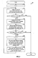
- FIG. 1 is a flow diagram of an embodiment of a process for allocating the total transmit power among the eigenmodes in a MIMO system using power reallocation;
- FIG. 2 is a flow diagram of an embodiment of a process for allocating the total transmit power among the transmission channels in a multi-channel communication system using power reallocation;
- FIG. 3 is a flow diagram of an embodiment of a process for allocating the total transmit power among the eigenmodes in a MIMO system that supports a set of discrete data rates;
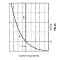
- FIG. 4A shows two plots for spectral efficiency versus effective SNR.
- FIGS. 4B and 4C show plots of spectral efficiency versus effective SNR for a communication system that supports a set of discrete data rates
- FIG. 5 is a flow diagram of an embodiment of a process for allocating the total available transmit power to a set of eigenmodes based on the water-filling scheme
- FIGS. 6A and 6B graphically illustrate the allocation of the total transmit power to the eigenmodes based on the water-filling scheme.
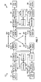
- FIG. 7 is a block diagram of an embodiment of a transmitter system and a receiver system.
- the techniques described herein for allocating/reallocating transmit power to transmission channels may be used for various multi-channel communication systems.
- Such multi-channel communication systems include multiple-input, multiple-output (MIMO) communication systems, orthogonal frequency division multiplexing (OFDM) communication systems, MIMO systems that utilize OFDM (i.e., MIMO-OFDM systems), and others.
- the multi-channel communication systems may also implement code division multiple access (CDMA), time division multiple access (TDMA), frequency division multiple access (FDMA), or some other multiple access techniques.
- CDMA code division multiple access
- TDMA time division multiple access
- FDMA frequency division multiple access
- Multiple access communication systems can support concurrent communication with a number of terminals (i.e., users). For clarity, certain aspects and embodiments of the invention are described specifically for a MIMO system such as a multiple-antenna wireless communication system.
- a MIMO system employs multiple ( N T ) transmit antennas and multiple ( N R ) receive antennas for data transmission.
- a MIMO channel formed by the N T transmit and N R receive antennas may be decomposed into N S independent channels, with N S ⁇ min ⁇ N T , N R ⁇ .
- Each of the N S independent channels is also referred to as a spatial subchannel (or a transmission channel) of the MIMO channel.
- the number of spatial subchannels is determined by the number of eigenmodes for the MIMO channel, which in turn is dependent on a channel response matrix, H , that describes the response between the N T transmit and N R receive antennas.
- ⁇ y i ⁇ is the entry received on the i -th received antenna and i ⁇ ⁇ 1, ..., N R ⁇ ;
- AWGN additive white Gaussian noise
- the MIMO channel is assumed to be a flat-fading, narrowband channel.
- the elements of the channel response matrix, H are scalars, and the coupling, h i,j , between each transmit-receive antenna pair can be represented by a single scalar value.
- the power allocation/reallocation techniques described herein may also be applied to a frequency selective channel having different channel gains at different frequencies.
- the operating bandwidth may be divided into a number of (equal or unequal) frequency bands such that each band may be considered as a flat-fading channel. The response of the individual bands may then be considered in the allocation/reallocation of the total transmit power.
- the d i are referred to as the singular values of the channel response matrix, H .
- the singular value decomposition is a matrix operation known in the art and described in various references. One such reference is a book by Gilbert Strang entitled “Linear Algebra and Its Applications,” Second Edition, Academic Press, 1980 .
- the singular value decomposition decomposes the channel response matrix, H , into two unitary matrices, U and V , and the diagonal matrix, D .
- Matrix D is descriptive of the eigenmodes of the MIMO channel, which correspond to the spatial subchannels.
- the pre-multiplication of the signal vector, s , by the matrix V and the pre-multiplication of the received vector, y , by the matrix U H results in an effective diagonal channel, D , which is the transfer function between the signal vector, s , and the recovered vector, r .
- D the transfer function between the signal vector, s , and the recovered vector, r .
- the MIMO channel is decomposed into N S independent, non-interfering, orthogonal, and parallel channels. These independent channels are also referred to as the spatial subchannels of the MIMO channel.
- Diagonalization of the MIMO channel to obtain N S orthogonal spatial subchannels can be achieved if the transmitter is provided with an estimate of the channel response matrix, H .
- a peak transmit power of P max may be imposed on each of the N T transmit antennas.
- the total transmit power, P tot may be allocated to the N S non-zero eigenmodes (i.e., the spatial subchannels) based on various schemes. If the objective is to maximize capacity (i.e., spectral efficiency), then the total transmit power, P tot , may be allocated to the spatial subchannels by a "water-filling" scheme.
- the water-filling scheme is analogous to pouring a fixed amount of water into a vessel with an irregular bottom, where each eigenmode corresponds to a point on the bottom of the vessel, and the elevation of the bottom at any given point corresponds to the inverse of the signal-to-noise ratio (SNR) associated with that eigenmode.
- SNR signal-to-noise ratio
- a low elevation thus corresponds to a high SNR and, conversely, a high elevation corresponds to a low SNR.
- the total transmit power, P tot is then "poured" into the vessel such that the lower points in the vessel (i.e., higher SNRs) are filled first, and the higher points (i.e., lower SNRs) are filled later.
- the power distribution is dependent on the total transmit power, P tot , and the depth of the vessel over the bottom surface.
- the water surface level for the vessel after all of the total transmit power has been poured is constant over all points in the vessel.
- the points with elevations above the water surface level are not filled (i.e., eigenmodes with SNRs below a particular threshold are not used).
- the water-filling distribution is described by Robert G. Gallager, in "Information Theory and Reliable Communication," John Wiley and Sons, 1968 .
- Capacity is defined as the highest spectral efficiency at which information can be communicated with an arbitrarily low probability of error, and is typically given in unit of bits per second per Hertz (bps/Hz).
- the water-filling scheme can optimally allocate the total transmit power to the N S spatial subchannels such that capacity is achieved.
- the water-filling scheme distributes the total transmit power, P tot , over the eigenmodes in such a way that the eigenmode with the lowest noise variance (i.e., the highest SNR) receives the greatest fraction of the total power.
- the spectral efficiency of each eigenmode may be determined based on a particular monotonically increasing function in SNR.
- One function that may be used for spectral efficiency is the capacity function shown in equation (6).
- FIG. 4A shows two plots for spectral efficiency versus SNR.
- Plot 412 shows spectral efficiency increasing logarithmically with SNR as computed based on equation (10). Equation (10) assumes that an increase in SNR results in increasingly higher spectral efficiency. However, in a practical communication system, there may be an upper limit on spectral efficiency, which may be dictated, for example, by the maximum data rate supported by the system on any given data stream.
- Plot 414 shows spectral efficiency increasing logarithmically at lower SNRs and saturating at ⁇ sat , which is the upper limit on spectral efficiency. Saturation occurs when an increase in SNR no longer produces an increase in spectral efficiency.
- the SNR at which spectral efficiency saturates is denoted as ⁇ sat (i.e., ⁇ sat ⁇ ⁇ sat ).
- the allocation of the total transmit power by the water-filling scheme may result in some eigenmodes being operated in the saturation region (i.e., ⁇ i > ⁇ sat ) and the remaining eigenmodes being operated below this region (i.e., ⁇ i ⁇ ⁇ sat ) .
- An eigenmode is deemed as being operated in the saturation region if it is allocated more transmit power than necessary to achieve the required SNR, which is ⁇ sat if the objective is to achieve the maximum possible spectral efficiency, ⁇ sat .
- the effective SNR mentioned above there may be an upper limit on the SNR allowed at the receiver (i.e., the effective SNR mentioned above) for each eigenmode, which may also be represented as ⁇ sat .
- the effective SNR the effective SNR mentioned above
- the excess transmit power that increases the SNR beyond ⁇ sat cannot be used on that eigenmode because of the imposed upper limit on SNR.
- This excess transmit power may be more beneficially distributed among the other eigenmodes operating below ⁇ sat .
- An aspect of the invention provides techniques to allocate/reallocate the total transmit power to the eigenmodes such that higher overall system spectral efficiency and/or other benefits may be achieved.
- the total transmit power may be initially allocated to the eigenmodes based on a particular power allocation scheme.
- the initial allocation may result in more power being allocated to some eigenmodes than needed to achieve the required SNR (e.g., the ⁇ sat needed to support the saturation spectral efficiency, ⁇ sat ) , which would then result in these eigenmodes being operated in the saturation region.
- the techniques described herein advantageously reallocate the excess transmit power of eigenmodes operated in the saturation region to other eigenmodes operated below the saturation region. In this way, higher spectral efficiency may be achieved for the "poorer" eigenmodes without sacrificing the performance of the "better” eigenmodes.
- FIG. 1 is a flow diagram of an embodiment of a process 100 for allocating the total transmit power among the eigenmodes in the MIMO system.
- This process initially allocates the total transmit power, P tot , to the N S eigenmodes based on a particular power allocation scheme (e.g., the water-filling scheme). If any of the eigenmodes is allocated more transmit power then needed to achieve the required SNR (i.e., operated in the saturation region), then the total excess transmit power for these eigenmodes is determined and reallocated to the other eigenmodes.
- a particular power allocation scheme e.g., the water-filling scheme
- the process may be performed (or iterated) one or more times until either (1) no excess transmit power is available for reallocation, or (2) all eigenmodes are in the saturation region.
- n 1
- N S eigenmodes the allocation of the total transmit power
- I ( n ) ⁇ 1, ..., N S ⁇ .
- set I(n) would include less than N S eigenmodes or may even be an empty set.
- the process terminates. Otherwise, if set I ( n ) is not empty, then the total transmit power, P tot ( n ) , available for allocation for this iteration is determined, at step 118.
- the total transmit power, P tot ( n ) available for all N T transmit antennas may be determined as shown in equation (5). This assumes that each transmit antenna will be operated at the peak transmit power, P max . And for each subsequent iteration, the total transmit power, P tot ( n ), available for that iteration may be determined as described below.
- the total available transmit power, P tot ( n ), is then allocated to the eigenmodes in set I ( n ) based on the selected power allocation scheme, at step 120.
- Various schemes may be used for power allocation such as, for example, the water-filling scheme, a uniform allocation scheme that allocates equal amount of transmit power to all eigenmodes, and possibly other schemes.
- the transmit power may also be allocated based on schemes that may take into consideration other factors such as, for example, fairness, one or more system and/or terminal metrics, and so on.
- the water-filling scheme is used to distribute the total available transmit power, P tot ( n ), to the eigenmodes in set I ( n ).
- the result of the water-filling procedure is a specific transmit power, P i ( n ), allocated to each eigenmode in set I ( n ), for i ⁇ I ( n ).
- the power allocation is dependent on the total available transmit power, P tot ( n ), and the eigenvalues, ⁇ i , for the eigenmodes in set I ( n ).
- Each eigenmode in the saturation region, which is included in set J is then allocated the minimum amount of transmit power needed to achieve the required SNR (e.g., ⁇ sat ) , at step 126.
- the transmit power saved by allocating each eigenmode in set J with the minimum power to achieve its required SNR is then determined, at step 128.
- This total excess transmit power, ⁇ P ( n ) may now be reallocated to the eigenmodes that are still operated below the saturation region. The process then returns to step 114.
- the set of eigenmodes, I ( n ), to be allocated transmit power in this iteration is defined, at step 114.
- Set I ( n ) may be defined by removing the eigenmodes in set J (i.e., the eigenmodes that were in the saturation region) from set I ( n- 1) defined for the previous iteration.
- Set I ( n ) for the current iteration thus only includes eigenmodes that are currently not in saturation. If the new set I ( n ) is empty, as determined at step 116, then all eigenmodes are operated in the saturation region and no further reallocation of transmit power is needed, and the process terminates.
- the total transmit power, P tot ( n ), available for the current iteration is then allocated to the eigenmodes in the new set I ( n ) based on the selected power allocation scheme, at step 120.
- the process shown in FIG. 1 proceeds until either (1) all of the excess transmit power has been reallocated to the eigenmodes not in the saturation region (as determined in step 122, which may occur for low SNR operating environment), or (2) all eigenmodes are in the saturation region (as determined in step 116, which may occur for high SNR operating environment).
- spectral efficiency is a strictly increasing function of the effective SNR, as shown by equation (10).
- the transmit power allocation/reallocation techniques described herein may also be used if spectral efficiency is a non-linear function of the effective SNR. In such cases, the non-linearity may be taken into account when allocating/reallocating the available transmit power to the eigenmodes.
- each eigenmode may be associated with a particular setpoint, which is the target SNR needed to achieve the desired performance.
- the same or different setpoints may be used for the N s eigenmodes.
- the total transmit power may then be allocated to the eigenmodes such that the setpoint(s) are achieved for these eigenmodes.
- the process shown in FIG. 1 may be used to reallocate transmit power to the eigenmodes, where the required SNR is now the setpoint instead of ⁇ sat .
- the determination of whether or not a particular eigenmode is operated in the saturation region may thus be dependent on the specific setpoint associated with that eigenmode (instead of a common SNR, such as ⁇ sat ).
- the transmit power allocation/reallocation techniques described herein may also be used for other multi-channel communication systems, such as OFDM systems, MIMO-OFDM systems, and so on.
- An OFDM system effectively partitions the system bandwidth into a number of (N F ) frequency subchannels, which are also commonly referred to as frequency bins or subbands.
- Each frequency subchannel is associated with a respective subcarrier (or frequency tone) upon which data may be modulated.
- a modulation symbol may be transmitted on each of the N F frequency subchannels.
- the frequency subchannels of the OFDM system may experience frequency selective fading (i.e., different amounts of attenuation for different frequency subchannels).
- the specific response for the frequency subchannels is dependent on the characteristics (e.g., the fading and multipath effects) of the propagation path between the transmit and receive antennas. Consequently, different effective SNRs may be achieved for different frequency subchannels for a given amount of transmit power.
- the total transmit power may be allocated to the N F frequency subchannels in similar manner as that described above for the eigenmodes.
- a MIMO-OFDM system includes N F frequency subchannels for each of the N s eigenmodes.
- the frequency subchannels of each eigenmode in the MIMO-OFDM system may similarly experience different channel conditions and may achieve different SNRs for a given amount of transmit power. In this case, the total transmit power may also be allocated to the N C transmission channels in similar manner as that described above for the eigenmodes.
- FIG. 2 is a flow diagram of an embodiment of a process 200 for allocating the total transmit power among N C transmission channels in a multi-channel communication system.
- Process 200 may be used for any multi-channel communication system, including a MIMO system, an OFDM system, a MIMO-OFDM system, and so on.
- Process 200 initially allocates the total transmit power, P tot , to the N C transmission channels based on a particular power allocation scheme (e.g., the water-filling scheme). If any of the transmission channels are allocated more transmit power than needed to achieve the required SNR (i.e., operated in the saturation region), then the total excess transmit power for these transmission channels is determined and reallocated to the other transmission channels. Again, the transmit power allocation may be performed (or iterated) one or more times until either (1) no excess transmit power is available for reallocation, or (2) all transmission channels are in the saturation region.
- a particular power allocation scheme e.g., the water-filling scheme
- the set of all transmission channels, I ( n ), to be allocated transmit power for this iteration is then defined, at step 214.
- N C N S for a MIMO system
- N C N F for an OFDM system
- Set I ( n ) would then include less than N C transmission channels or may even be an empty set.
- Each transmission channel in the saturation region is then allocated the minimum amount of transmit power needed to achieve the applicable setpoint, at step 226.
- the transmit power saved by allocating each transmission channel in set J with the minimum power to achieve its setpoint is then determined, at step 228.
- the total excess transmit power may now be reallocated to transmission channels that are still operated below the saturation region. The process then returns to step 214.
- the set of transmission channels, I ( n ) , to be allocated transmit power in this iteration is defined to include only transmission channels that are currently not in saturation, at step 214. If the new set I ( n ) is empty, as determined at step 216, then all transmission channels are operated in the saturation region, no further reallocation of transmit power is needed, and the process terminates. Otherwise, if the new set I ( n ) is not empty, then the total transmit power, P tot ( n ) , available for the current iteration is determined, at step 218, and then allocated to the transmission channels in the new set I ( n ) based on the selected power allocation scheme, at step 220.
- the process shown in FIG. 2 proceeds until either (1) all of the excess transmit power has been reallocated to the transmission channels not in the saturation region (as determined in step 222), or (2) all transmission channels are in the saturation region (as determined in step 216).
- all transmission channels may be considered for power allocation in each iteration.
- the power allocation may be performed such that the transmission channels for only one dimension are considered at any given time.
- power allocation may be performed on a per-transmit antenna basis whereby the total transmit power, P max , for each transmit antenna is allocated to the frequency subchannels of that transmit antenna.
- Each group may include any number of transmission channels and may be associated with a respective setpoint.
- Each group may include, for example, the transmission channels to be used for an independent data stream, which may be associated with a particular data rate and a particular coding and modulation scheme.
- each group may be associated with the transmission channels to be assigned to a different receiver.
- the receiver may provide an indication of the quality of each transmission channel that may be used for data transmission.
- the information reported by the receiver may be in the form of an estimated SNR, a supported data rate, and so on.
- the transmitter can then allocate transmit power to the transmission channels based on the reported information to achieve better utilization of the available transmit power. For example, if the estimated SNR for a given transmission channel is higher than needed to achieve a designated data rate, or if the data rate reported as being supported by a given transmission channel is greater than the system's maximum data rate, then less transmit power may be allocated for the transmission channel.
- the specific amount of transmit power to be allocated may be determined based on the reported information (e.g., the estimated SNR or supported data rate).
- the total available transmit power, P tot (2) is then allocated to the eigenmodes in set I (2).
- the total spectral efficiency, ⁇ tot may then be obtained by summing the spectral efficiency achieved by each of the eigenmodes.
- a gain of 2 to 5 dB may be achieved at intermediate SNRs by reallocating the excess transmit power of eigenmodes in the saturation region to other eigenmodes not in the saturation region.
- the eigenmodes do not enter the saturation region, and there is little or no transmit power to reallocate.
- most or all of the eigenmodes may be operated in the saturation region, and the transmit power reallocation may be used to reduce the amount of interference, which may improve the performance of neighboring cells.
- the spectral efficiency, ⁇ is a continuous function of the effective SNR, ⁇ , as shown in equation (10). Furthermore, the system described above allows the spectral efficiency to be any real value that does not exceed the saturation point, ⁇ sat .
- a typical communication system may only support a set of discrete data rates for each spatial subchannel, and the data rate sets may or may not be identical for the subchannels.
- FIG. 4B shows a plot of spectral efficiency versus effective SNR for a certain eigenmode in a communication system that supports a set of discrete data rates for each eigenmode.
- Each set of data rates may be converted to a set of discrete spectral efficiencies and is further associated with a set of discrete effective SNRs needed to achieve a target frame error rate (FER) for a data transmission on the spatial subchannel.
- FER target frame error rate
- the discrete spectral efficiencies are labeled as ⁇ i ( d ) on the vertical axis and occur at the corresponding SNRs of ⁇ i ( d ) , where i (i ⁇ I ) refers to eigenmode i and d (1 ⁇ d ⁇ D i ) is used to enumerate through the D i discrete data rates associated with eigenmode i .
- the spectral efficiency function for this system is shown by plot 422 (the thick solid line).
- the discrete operating points at (( ⁇ i ( d ), ⁇ i ( d )) corresponding to the minimum SNR necessary to achieve a certain spectral efficiency are shown by the solid circles 424.
- an increase in SNR may not offer an improvement in spectral efficiency. Therefore, allocating more transmit power than necessary to achieve the target FER at the operating spectral efficiency would result in an ineffective use of the additional transmit power.
- the excess power allocation/reallocation techniques described above may be used for systems with discrete data rates and setpoints.
- FIG. 3 is a flow diagram of an embodiment of a process 300 for allocating the total transmit power among the eigenmodes in a MIMO system that supports a set of discrete data rates.
- the total transmit power, P tot is allocated to the N S eigenmodes based on a particular power allocation scheme (e.g., the water-filling scheme), at step 312.
- each eigenmode is allocated transmit power of P i , for i ⁇ I, where the power allocated to a given eigenmode may be zero. If the effective SNR of an eigenmode does not fall on one of the discrete operating points, then some transmit power allocated to this eigenmode is used inefficiently and power control may be employed.
- each eigenmode in set K is allocated the minimum amount of transmit power necessary to meet the current spectral efficiency contribution of that eigenmode, at step 318. This is achieved by backing off (or reducing) the transmit power allocated to each eigenmode in K so that the eigenmode is now operating at the discrete operating point.
- FIG. 4B also shows an example system whereby the initial operating points of the three eigenmodes, shown in by dashed lines 426a through 426c, do not lie on the discrete operating points.
- the transmit power for each of these eigenmodes is reduced by a backed-off amount, BO k , for k ⁇ K , so that the eigenmode is operating at a lower transmit power without incurring a loss in spectral efficiency.
- the excess transmit power, ⁇ P ⁇ , determined in step 320 is reallocated among the eigenmodes in set J in various different combinations (e.g., in all possible combinations), at step 326.
- This can be performed based on knowledge of the spectral efficiency as a function of the effective SNR for each eigenmode (e.g., as shown by plot 422 in FIG. 4B).
- a table of incremental SNRs, ⁇ j ( d ), and the corresponding gains in spectral efficiency, ⁇ j ( d ) may be determined for each operating point d of each eigenmode j in set J.
- FIG. 4B illustrates both the incremental SNR and the resulting gain in spectral efficiency for the given spectral efficiency function.
- ⁇ P j ( d ) is the incremental power required to achieve the next higher spectral efficiency on eigenmode j from the current operating point, d .
- the reallocation of the excess transmit power may be performed so that the highest possible gain in spectral efficiency is achieved. This may be achieved by performing an exhaustive search (or evaluation) of all possible reallocations of the excess transmit power, ⁇ P ⁇ , to all eigenmodes in set J using the incremental transmit power and the corresponding gain in spectral efficiency obtained from equations (19) and (18), respectively, at step 328. Finally, the excess transmit power is distributed according to the reallocation that yields the highest gain in spectral efficiency, at step 330. The process then terminates.
- the excess transmit power is reallocated to one eigenmode at a time starting with the best eigenmode. For example, some excess transmit power may be reallocated to the highest eigenmode in set J (e.g., just enough power to move this eigenmode to the next higher spectral efficiency level). Some remaining excess transmit power may then be reallocated to the next highest eigenmode in set J , and the process can continue in this manner until all excess transmit power has been reallocated.
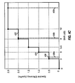
- FIG. 4C shows the spectral efficiency versus effective SNR for the above example system.
- the same set of discrete data rates is assumed to apply for all eigenmodes and is associated with the spectral efficiency function shown by plot 432.
- the saturation SNR for each eigenmode is thus, ⁇ sat , (i)
- dB 12dB, ⁇ i ⁇ I .
- the new transmit power allocations push the operating points of the three eigenmodes to the discrete operating points.
- Table 1 lists the incremental SNR, ⁇ j ( d ), for each operating point, d , and each eigenmode, for j ⁇ J . Because the discrete data rates are the same for all eigenmodes in this example, the subscript j is dropped and the incremental SNR is expressed as ⁇ ( d ).
- the incremental transmit power, ⁇ P j (d), on eigenmode j is a function of the eigenvalue on eigenmode j , , ⁇ j .
- the ⁇ P j (d) s are shown for each eigenmode, for j ⁇ J , and for each operating point, d , as calculated using equation (19).
- the techniques described herein for allocating/reallocating transmit power to transmission channels may be used for various multi-channel communication systems, including MIMO systems, OFDM systems, MIMO-OFDM systems, and so on. These techniques may be advantageously used for systems having a saturation spectral efficiency, ⁇ sat , (as illustrated in FIG. 4A) and for systems supporting one or more sets of discrete data rates for the transmission channels (as illustrated in FIG. 4B).
- ⁇ sat saturation spectral efficiency
- FIG. 4B The process shown in FIG. 3 may be modified to allocate/reallocate transmit power to transmission channels (instead of eigenmodes).
- the techniques described above may be used to allocate/reallocate the total transmit power to maximize spectral efficiency (e.g., to achieve the highest possible overall throughput or aggregate data rate for the transmission channels).
- the aggregate data rate may be limited or specified.
- the techniques described above may be modified and used to allocate the minimum amount of transmit power that achieves the specified aggregate data rate.
- the allocation of the minimum transmit power that achieves a particular spectral efficiency may be performed in various manners, which may be dependent on the design and capabilities of the communication system. Several possible schemes are provided below.
- the minimum transmit power allocation for a specified spectral efficiency may be achieved as follows.
- an iterative search may be performed to determine the minimum transmit power allocation for a specified spectral efficiency.
- the excess spectral efficiency may be determined as described above. If the excess spectral efficiency exceeds a particular threshold (e.g., a particular percentage over the specified spectral efficiency), then a new transmit power allocation may be determined that reduces the excess spectral efficiency.
- the MIMO channel can be diagonalized into N S orthogonal channels using singular-value decomposition, as described above.
- the performance on each spatial subchannel is limited by the additive white Gaussian noise (AWGN) of variance ⁇ 2 .
- AWGN additive white Gaussian noise
- FIG. 5 is a flow diagram of an embodiment of a process 500 for allocating the total available transmit power to a set of eigenmodes.
- Process 500 is one specific implementation of the water-filling scheme, and may be used for steps 120, 220, and 312 in FIGS. 1, 2, and 3, respectively.
- the water-filling scheme determines the transmit power, P i , for i ⁇ I , to be allocated to the eigenmodes in set I given the total transmit power, P tot , available at the transmitter, the eigenvalues, ⁇ i , and the noise variance, ⁇ 2 .
- set I(n) is defined to include all the eigenmodes (i.e., 1 ⁇ i ⁇ N S ) , at step 514.
- the cardinality (or length) of set I ( n ), L I ( n )
- the total "effective" power, P TOTAL , to be distributed across the eigenmodes in set I(n) is next determined, at step 518.
- FIG. 6A graphically illustrates the total effective power for an example system with three eigenmodes.
- the total effective power is represented by the area in the shaded and unshaded regions in FIG. 6A.
- the total transmit power is then allocated to the eigenmode in set I ( n ).
- the final power level is constant across all eigenmodes. This final power level is determined by dividing P TOTAL by the number of eigenmodes in set I ( n ) , L l ( n ) . The amount of power allocated to eigenmode i is then determined by subtracting the inverse SNR of that eigenmode, ⁇ 2 / ⁇ i , from the final power level, P TOTAL / L I (n), as given by equation (21) and shown in FIG. 6A. Each eigenmode in set I ( n ) is allocated transmit power, P i , by step 522. Steps 524 and 526 are part of a loop to allocate transmit power to each eigenmode in set I ( n ) .
- FIG. 6B shows a situation where the power allocation by the water-filling scheme results in an eigenmode receiving negative power, which is the case when (P TOTAL / L 1 ( n )) ⁇ ( ⁇ 2 / ⁇ i ).
- the total transmit power is divided among the remaining eigenmodes in set I ( n ) .
- the procedure continues until all eigenmodes in set I ( n ) have been allocated positive power, as determine in step 528.
- the eigenmodes not in set I ( n ) are allocated zero power.
- the water-filling scheme has been described specifically for eigenmodes.
- the water-filling scheme may be performed for any type of transmission channels (e.g., spatial subchannels, frequency subchannels, or frequency subchannels of spatial subchannels, depending on the system being implemented).
- the process shown in FIG. 5 may thus be modified to allocate transmit power to transmission channels (instead of eigenmodes).
- FIG. 7 is a block diagram of an embodiment of a transmitter system 710 and a receiver system 750, which are capable of implementing various aspects and embodiments of the invention.
- traffic data is provided from a data source 712 to a transmit (TX) data processor 714, which formats, codes, and interleaves the traffic data based on one or more coding schemes to provide coded data.
- the coded traffic data may then be multiplexed with pilot data using, e.g., time division multiplex (TDM) or code division multiplex (CDM) in all or a subset of the transmission channels to be used for data transmission.
- TDM time division multiplex
- CDM code division multiplex
- the pilot data is typically a known data pattern processed in a known manner, if at all.
- the multiplexed pilot and coded traffic data is then modulated (i.e., symbol mapped) based on one or more modulation schemes (e.g., BPSK, QSPK, M-PSK, or M-QAM) to provide modulation symbols.
- modulation schemes e.g., BPSK, QSPK, M-PSK, or M-QAM
- the data rate, coding, interleaving, and modulation for each transmission channel or each group of transmission channels may be determined by various controls provided by a controller 730.
- the modulation symbols are then provided to a TX MIMO processor 720 and further processed.
- the processing by TX MIMO processor 720 includes (1) decomposing an estimate of the channel response matrix, H , to obtain the unitary matrix, V , and the diagonal matrix, D , (2) pre-multiplying the modulation symbols (i.e., the signal vector s ) with the unitary matrix V , and (3) demultiplexing the pre-conditioned symbols (i.e., the transmit vector x ) into N T symbol streams.
- the processing by TX MIMO processor 720 simply includes demultiplexing , the modulation symbols into N T symbol streams (i.e., no preconditioning of the symbols with the matrix V ).
- TX MIMO processor 720 may further scale each symbol by an appropriate weight determined based on the amount of transmit power allocated to the transmission channel used for that symbol.
- the N T (weighted) symbol streams are then provided to transmitters (TMTR) 722a through 722t.
- Each transmitter 722 receives and processes a respective symbol stream.
- each transmitter transforms the symbols (e.g., using the IFFT) to form OFDM symbols, and may further append a cyclic prefix to each OFDM symbol to form a corresponding transmission symbol.
- Each transmitter also converts the symbol stream into one or more analog signals and further conditions (e.g., amplifies, filters, and quadrature modulates) the analog signals to generate a modulated signal suitable for transmission over the MIMO channel.
- N T modulated signals from transmitters 722a through 722t are then transmitted from N T antennas 724a through 724t, respectively.
- the transmitted modulated signals are received by N R antennas 752a through 752r, and the received signal from each antenna 752 is provided to a respective receiver (RCVR) 754.
- Each receiver 754 conditions (e.g., filters, amplifies, and downconverts) the received signal and digitizes the conditioned signal to provide a respective stream of samples.
- Each sample stream may further be processed (e.g., demodulated with the recovered pilot) to obtain a corresponding stream of received symbols (denoted as y ).
- a RX MIMO processor 760 then receives and processes the N R received symbol streams to provide N T recovered symbol streams.
- the processing by RX MIMO processor 760 may include (1) decomposing the estimated channel response matrix to obtain the unitary matrix, U , (2) pre-multiplying the received symbols (i.e., the vector y ) with the unitary matrix, U H , to provide the recovered symbols (i.e., the vector r ), and (3) equalizing the recovered symbols to obtain equalized symbols.
- a receive (RX) data processor 762 then demodulates, deinterleaves, and decodes the equalized symbols to recover the transmitted traffic data.
- the processing by RX MIMO processor 760 and RX data processor 762 is complementary to that performed by TX MIMO processor 720 and TX data processor 714, respectively, at transmitter system 710.
- RX MIMO processor 760 may further derive an estimate of the channel response matrix, H , for the MIMO channel, the SNRs for the transmission channels, and so on, and provide these quantities to a controller 770.
- RX data processor 762 may also provide the status of each received frame or packet, one or more other performance metrics indicative of the decoded results, and possibly other information.
- Controller 770 collects channel state information (CSI), which may comprise all or some of the information received from RX MIMO processor 760 and RX data processor 762. The CSI is then processed by a TX data processor 778, modulated by a modulator 780, conditioned by transmitters 754a through 754r, and transmitted back to transmitter system 710.
- CSI channel state information
- the modulated signals from receiver system 750 are received by antennas 724, conditioned by receivers 722, demodulated by a demodulator 740, and processed by a RX data processor 742 to recover the CSI reported by the receiver system.
- the CSI is then provided to controller 730 and used to generate various controls for TX data processor 714 and TX MIMO processor 720.
- Controllers 730 and 770 direct the operation at the transmitter and receiver systems, respectively.
- Memories 732 and 772 provide storage for program codes and data used by controllers 730 and 770, respectively.
- controller 730 receives the CSI from receiver system 750, which may include the channel response matrix or some other information descriptive of the characteristics of the MIMO channel. Controller 730 then allocates the total transmit power to the transmission channels such that excess transmit power of transmission channels operated in the saturation region are reallocated to other transmission channels not in the saturation region, as described above.
- the transmit power, P i allocated to each transmission channel may then determine the data rate and the coding and modulation scheme to be used for that transmission channel.
- the transmit power allocation/reallocation techniques described herein may be implemented by various means. For example, these techniques may be implemented in hardware, software, or a combination thereof.
- the elements used to allocate/reallocate transmit power to transmission channels may be implemented within one or more application specific integrated circuits (ASICs), digital signal processors (DSPs), digital signal processing devices (DSPDs), programmable logic devices (PLDs), field programmable gate arrays (FPGAs), processors, controllers, micro-controllers, microprocessors, other electronic units designed to perform the functions described herein, or a combination thereof.
- ASICs application specific integrated circuits
- DSPs digital signal processors
- DSPDs digital signal processing devices
- PLDs programmable logic devices
- FPGAs field programmable gate arrays
- processors controllers, micro-controllers, microprocessors, other electronic units designed to perform the functions described herein, or a combination thereof.
- the transmit power allocation/reallocation may be implemented with modules (e.g., procedures, functions, and so on) that perform the functions described herein.
- the software codes may be stored in a memory unit (e.g., memory 732 in FIG. 7) and executed by a processor (e.g., controller 730).
- the memory unit may be implemented within the processor or external to the processor, in which case it can be communicatively coupled to the processor via various means as is known in the art.
Priority Applications (2)
| Application Number | Priority Date | Filing Date | Title |
|---|---|---|---|
| EP07019187A EP1871012B1 (en) | 2002-01-23 | 2003-01-22 | Reallocation of excess power in a wireless communication system |
| EP10006914A EP2230869A3 (en) | 2002-01-23 | 2003-01-22 | Reallocation of excess power for full channel-state information (CSI) multiple-input, multiple-output (MIMO) systems |
Applications Claiming Priority (3)
| Application Number | Priority Date | Filing Date | Title |
|---|---|---|---|
| US10/056,275 US7020482B2 (en) | 2002-01-23 | 2002-01-23 | Reallocation of excess power for full channel-state information (CSI) multiple-input, multiple-output (MIMO) systems |
| US56275 | 2002-01-23 | ||
| PCT/US2003/001949 WO2003063384A1 (en) | 2002-01-23 | 2003-01-22 | Reallocation of excess power for full channel-state information (csi) multiple-input, multiple-output (mimo) systems |
Related Child Applications (1)
| Application Number | Title | Priority Date | Filing Date |
|---|---|---|---|
| EP07019187A Division EP1871012B1 (en) | 2002-01-23 | 2003-01-22 | Reallocation of excess power in a wireless communication system |
Publications (2)
| Publication Number | Publication Date |
|---|---|
| EP1468505A1 EP1468505A1 (en) | 2004-10-20 |
| EP1468505B1 true EP1468505B1 (en) | 2007-10-03 |
Family
ID=22003337
Family Applications (3)
| Application Number | Title | Priority Date | Filing Date |
|---|---|---|---|
| EP03707488A Expired - Lifetime EP1468505B1 (en) | 2002-01-23 | 2003-01-22 | Reallocation of excess power for full channel-state information (csi) multiple-input, multiple-output (mimo) systems |
| EP07019187A Expired - Lifetime EP1871012B1 (en) | 2002-01-23 | 2003-01-22 | Reallocation of excess power in a wireless communication system |
| EP10006914A Withdrawn EP2230869A3 (en) | 2002-01-23 | 2003-01-22 | Reallocation of excess power for full channel-state information (CSI) multiple-input, multiple-output (MIMO) systems |
Family Applications After (2)
| Application Number | Title | Priority Date | Filing Date |
|---|---|---|---|
| EP07019187A Expired - Lifetime EP1871012B1 (en) | 2002-01-23 | 2003-01-22 | Reallocation of excess power in a wireless communication system |
| EP10006914A Withdrawn EP2230869A3 (en) | 2002-01-23 | 2003-01-22 | Reallocation of excess power for full channel-state information (CSI) multiple-input, multiple-output (MIMO) systems |
Country Status (14)
| Country | Link |
|---|---|
| US (2) | US7020482B2 (ja) |
| EP (3) | EP1468505B1 (ja) |
| JP (3) | JP2006504287A (ja) |
| KR (2) | KR101008861B1 (ja) |
| CN (1) | CN100448176C (ja) |
| AT (2) | ATE375034T1 (ja) |
| BR (1) | BR0307054A (ja) |
| CA (1) | CA2473917A1 (ja) |
| DE (1) | DE60316663T2 (ja) |
| ES (1) | ES2292940T3 (ja) |
| HK (1) | HK1078187A1 (ja) |
| MX (1) | MXPA04007174A (ja) |
| TW (2) | TWI337471B (ja) |
| WO (1) | WO2003063384A1 (ja) |
Families Citing this family (136)
| Publication number | Priority date | Publication date | Assignee | Title |
|---|---|---|---|---|
| EP1182817B1 (en) | 2000-08-24 | 2007-12-26 | Sony Deutschland GmbH | Communication device for receiving and transmitting OFDM signals in a wireless communication system |
| CN1232063C (zh) * | 2002-01-21 | 2005-12-14 | 三星电子株式会社 | 用于在hsdpa系统中分配功率的设备和方法 |
| US7020482B2 (en) * | 2002-01-23 | 2006-03-28 | Qualcomm Incorporated | Reallocation of excess power for full channel-state information (CSI) multiple-input, multiple-output (MIMO) systems |
| US6862271B2 (en) * | 2002-02-26 | 2005-03-01 | Qualcomm Incorporated | Multiple-input, multiple-output (MIMO) systems with multiple transmission modes |
| US7613248B2 (en) * | 2002-06-24 | 2009-11-03 | Qualcomm Incorporated | Signal processing with channel eigenmode decomposition and channel inversion for MIMO systems |
| US7385915B2 (en) * | 2002-07-31 | 2008-06-10 | Nokia Corporation | Apparatus, and associated method, for facilitating communication allocation in a radio communication system |
| US8194770B2 (en) * | 2002-08-27 | 2012-06-05 | Qualcomm Incorporated | Coded MIMO systems with selective channel inversion applied per eigenmode |
| US6873606B2 (en) * | 2002-10-16 | 2005-03-29 | Qualcomm, Incorporated | Rate adaptive transmission scheme for MIMO systems |
| US8169944B2 (en) * | 2002-10-25 | 2012-05-01 | Qualcomm Incorporated | Random access for wireless multiple-access communication systems |
| US8170513B2 (en) | 2002-10-25 | 2012-05-01 | Qualcomm Incorporated | Data detection and demodulation for wireless communication systems |
| US7986742B2 (en) * | 2002-10-25 | 2011-07-26 | Qualcomm Incorporated | Pilots for MIMO communication system |
| US8320301B2 (en) * | 2002-10-25 | 2012-11-27 | Qualcomm Incorporated | MIMO WLAN system |
| US8208364B2 (en) * | 2002-10-25 | 2012-06-26 | Qualcomm Incorporated | MIMO system with multiple spatial multiplexing modes |
| US7002900B2 (en) * | 2002-10-25 | 2006-02-21 | Qualcomm Incorporated | Transmit diversity processing for a multi-antenna communication system |
| US8570988B2 (en) * | 2002-10-25 | 2013-10-29 | Qualcomm Incorporated | Channel calibration for a time division duplexed communication system |
| US20040081131A1 (en) | 2002-10-25 | 2004-04-29 | Walton Jay Rod | OFDM communication system with multiple OFDM symbol sizes |
| US7324429B2 (en) | 2002-10-25 | 2008-01-29 | Qualcomm, Incorporated | Multi-mode terminal in a wireless MIMO system |
| US8218609B2 (en) * | 2002-10-25 | 2012-07-10 | Qualcomm Incorporated | Closed-loop rate control for a multi-channel communication system |
| US8134976B2 (en) | 2002-10-25 | 2012-03-13 | Qualcomm Incorporated | Channel calibration for a time division duplexed communication system |
| US7242727B2 (en) * | 2003-03-31 | 2007-07-10 | Lucent Technologies Inc. | Method of determining transmit power for transmit eigenbeams in a multiple-input multiple-output communications system |
| WO2004114561A1 (ja) * | 2003-06-18 | 2004-12-29 | Nippon Telegraph And Telephone Corporation | 無線パケット通信方法および無線パケット通信装置 |
| US7245879B2 (en) * | 2003-08-08 | 2007-07-17 | Intel Corporation | Apparatus and associated methods to perform intelligent transmit power control with subcarrier puncturing |
| US7286609B2 (en) * | 2003-08-08 | 2007-10-23 | Intel Corporation | Adaptive multicarrier wireless communication system, apparatus and associated methods |
| US7440510B2 (en) * | 2003-09-15 | 2008-10-21 | Intel Corporation | Multicarrier transmitter, multicarrier receiver, and methods for communicating multiple spatial signal streams |
| US7379506B2 (en) * | 2003-09-23 | 2008-05-27 | Nokia Corporation | Apparatus, and associated method, for assigning data to transmit antennas of a multiple transmit antenna transmitter |
| US7616698B2 (en) | 2003-11-04 | 2009-11-10 | Atheros Communications, Inc. | Multiple-input multiple output system and method |
| US8705659B2 (en) * | 2003-11-06 | 2014-04-22 | Apple Inc. | Communication channel optimization systems and methods in multi-user communication systems |
| US7298805B2 (en) * | 2003-11-21 | 2007-11-20 | Qualcomm Incorporated | Multi-antenna transmission for spatial division multiple access |
| US9473269B2 (en) | 2003-12-01 | 2016-10-18 | Qualcomm Incorporated | Method and apparatus for providing an efficient control channel structure in a wireless communication system |
| US20050147022A1 (en) * | 2003-12-22 | 2005-07-07 | Texas Instruments Incorporated | Preamble transmit power tailoring system, a method of tailoring preamble transmit power and an OFDM transmitter employing the same |
| US7649833B2 (en) * | 2003-12-29 | 2010-01-19 | Intel Corporation | Multichannel orthogonal frequency division multiplexed receivers with antenna selection and maximum-ratio combining and associated methods |
| US7570953B2 (en) * | 2004-01-12 | 2009-08-04 | Intel Corporation | Multicarrier communication system and methods for link adaptation using uniform bit loading and subcarrier puncturing |
| US7333556B2 (en) * | 2004-01-12 | 2008-02-19 | Intel Corporation | System and method for selecting data rates to provide uniform bit loading of subcarriers of a multicarrier communication channel |
| GB2411550B (en) * | 2004-02-27 | 2006-07-12 | Toshiba Res Europ Ltd | Communications system, method and device |
| US10749582B2 (en) | 2004-04-02 | 2020-08-18 | Rearden, Llc | Systems and methods to coordinate transmissions in distributed wireless systems via user clustering |
| US9826537B2 (en) | 2004-04-02 | 2017-11-21 | Rearden, Llc | System and method for managing inter-cluster handoff of clients which traverse multiple DIDO clusters |
| US11309943B2 (en) | 2004-04-02 | 2022-04-19 | Rearden, Llc | System and methods for planned evolution and obsolescence of multiuser spectrum |
| US10187133B2 (en) | 2004-04-02 | 2019-01-22 | Rearden, Llc | System and method for power control and antenna grouping in a distributed-input-distributed-output (DIDO) network |
| US9312929B2 (en) | 2004-04-02 | 2016-04-12 | Rearden, Llc | System and methods to compensate for Doppler effects in multi-user (MU) multiple antenna systems (MAS) |
| US10277290B2 (en) | 2004-04-02 | 2019-04-30 | Rearden, Llc | Systems and methods to exploit areas of coherence in wireless systems |
| US10425134B2 (en) | 2004-04-02 | 2019-09-24 | Rearden, Llc | System and methods for planned evolution and obsolescence of multiuser spectrum |
| US7885354B2 (en) * | 2004-04-02 | 2011-02-08 | Rearden, Llc | System and method for enhancing near vertical incidence skywave (“NVIS”) communication using space-time coding |
| US8542763B2 (en) | 2004-04-02 | 2013-09-24 | Rearden, Llc | Systems and methods to coordinate transmissions in distributed wireless systems via user clustering |
| US11451275B2 (en) | 2004-04-02 | 2022-09-20 | Rearden, Llc | System and method for distributed antenna wireless communications |
| US11394436B2 (en) | 2004-04-02 | 2022-07-19 | Rearden, Llc | System and method for distributed antenna wireless communications |
| US10886979B2 (en) | 2004-04-02 | 2021-01-05 | Rearden, Llc | System and method for link adaptation in DIDO multicarrier systems |
| US8654815B1 (en) | 2004-04-02 | 2014-02-18 | Rearden, Llc | System and method for distributed antenna wireless communications |
| US9819403B2 (en) | 2004-04-02 | 2017-11-14 | Rearden, Llc | System and method for managing handoff of a client between different distributed-input-distributed-output (DIDO) networks based on detected velocity of the client |
| US10200094B2 (en) | 2004-04-02 | 2019-02-05 | Rearden, Llc | Interference management, handoff, power control and link adaptation in distributed-input distributed-output (DIDO) communication systems |
| US10985811B2 (en) | 2004-04-02 | 2021-04-20 | Rearden, Llc | System and method for distributed antenna wireless communications |
| US20050245280A1 (en) * | 2004-04-30 | 2005-11-03 | Ke Liu | Apparatus, and associated method, for facilitating closed-loop power control in a communication system utilizing a multiple transmit antenna configuration |
| US8923785B2 (en) * | 2004-05-07 | 2014-12-30 | Qualcomm Incorporated | Continuous beamforming for a MIMO-OFDM system |
| US9685997B2 (en) | 2007-08-20 | 2017-06-20 | Rearden, Llc | Systems and methods to enhance spatial diversity in distributed-input distributed-output wireless systems |
| EP2334001A1 (en) * | 2004-10-13 | 2011-06-15 | McMASTER UNIVERSITY | Operating environment analysis techniques for wireless communication systems |
| US20060098754A1 (en) * | 2004-10-21 | 2006-05-11 | Samsung Electronics Co., Ltd. | Beam and power allocation method for MIMO communication system |
| JP4589711B2 (ja) * | 2004-12-14 | 2010-12-01 | 富士通株式会社 | 無線通信システム及び無線通信装置 |
| US7623490B2 (en) * | 2004-12-22 | 2009-11-24 | Qualcomm Incorporated | Systems and methods that utilize a capacity-based signal-to-noise ratio to predict and improve mobile communication |
| US7747271B2 (en) * | 2005-03-02 | 2010-06-29 | Qualcomm Incorporated | Radiated power control for a multi-antenna transmission |
| WO2006093468A1 (en) * | 2005-03-04 | 2006-09-08 | Matsushita Electric Industrial Co., Ltd. | Transmit power allocation in wireless communication system |
| US20060234751A1 (en) * | 2005-04-19 | 2006-10-19 | Samsung Electronics Co., Ltd. | Power loading method and apparatus for throughput enhancement in MIMO systems |
| US8416862B2 (en) * | 2005-04-21 | 2013-04-09 | Broadcom Corporation | Efficient feedback of channel information in a closed loop beamforming wireless communication system |
| US7466749B2 (en) | 2005-05-12 | 2008-12-16 | Qualcomm Incorporated | Rate selection with margin sharing |
| US8358714B2 (en) * | 2005-06-16 | 2013-01-22 | Qualcomm Incorporated | Coding and modulation for multiple data streams in a communication system |
| KR101457830B1 (ko) * | 2005-09-29 | 2014-11-05 | 인터디지탈 테크날러지 코포레이션 | Mimo 빔형성 기반의 단일 반송파 주파수 분할 다중 접속 시스템 |
| US7852951B2 (en) * | 2005-09-30 | 2010-12-14 | Intel Corporation | Multicarrier receiver for multiple-input multiple-output wireless communication systems and method |
| CN100349388C (zh) * | 2005-10-20 | 2007-11-14 | 上海交通大学 | 多输入多输出系统的最小发射功率自适应调制方法 |
| US7715803B2 (en) * | 2005-12-20 | 2010-05-11 | Samsung Electronics Co., Ltd. | Methods and apparatus for constant-power loading asymmetric antenna configuration |
| US7697621B2 (en) * | 2005-12-22 | 2010-04-13 | Samsung Electronics Co., Ltd. | Method and system for power loading implementation detection in beamforming systems |
| US7656965B2 (en) * | 2005-12-29 | 2010-02-02 | Celeno Communications (Israel) Ltd. | Method of secure WLAN communication |
| US9071435B2 (en) | 2005-12-29 | 2015-06-30 | Celeno Communications Ltd. | System and method for tuning transmission parameters in multi-user multiple-input-multiple-output systems with aged and noisy channel estimation |
| US20070153760A1 (en) | 2005-12-29 | 2007-07-05 | Nir Shapira | Method, apparatus and system of spatial division multiple access communication in a wireless local area network |
| US20070153934A1 (en) * | 2005-12-29 | 2007-07-05 | Samsung Electronics Co., Ltd. | Constant uneven power loading in beamforming systems for high throughput wireless communications |
| US7672400B2 (en) * | 2005-12-29 | 2010-03-02 | Celeno Communications (Israel) Ltd. | Method of secure WLAN communication |
| US7751353B2 (en) | 2005-12-29 | 2010-07-06 | Celeno Communications (Israel) Ltd. | Device, system and method of securing wireless communication |
| US7881265B2 (en) * | 2006-03-15 | 2011-02-01 | Interdigital Technology Corporation | Power loading transmit beamforming in MIMO-OFDM wireless communication systems |
| US8126396B2 (en) * | 2006-11-09 | 2012-02-28 | Broadcom Corporation | Wireless network that utilizes concurrent interfering transmission and MIMO techniques |
| US7843802B2 (en) * | 2006-12-04 | 2010-11-30 | Nec Laboratories America, Inc. | Method for uplink multiuser OFM with constrained inputs |
| US8396502B2 (en) * | 2007-07-23 | 2013-03-12 | Alcatel Lucent | Power controlling method and corresponding base station |
| KR101346042B1 (ko) * | 2007-07-31 | 2013-12-31 | 재단법인서울대학교산학협력재단 | 다중 입/출력 통신 방법 및 이를 이용한 다중 입/출력 통신시스템 |
| US20090128410A1 (en) * | 2007-11-15 | 2009-05-21 | Nokia Corporation | Method, apparatus and computer readable medium providing power allocation for beamforming with minimum bler in an MIMO-OFDM system |
| EP2523361B1 (en) | 2007-12-20 | 2017-03-22 | Sony Corporation | Improved transmit power allocation for adaptive multi-carrier multiplexing MIMO systems |
| US8472967B2 (en) * | 2008-02-01 | 2013-06-25 | Qualcomm Incorporated | Allocating transmit power among two or more carriers assigned to a wireless communication device |
| US8345803B2 (en) * | 2008-10-02 | 2013-01-01 | Qualcomm Incorporated | Optimized finger assignment for improved multicarrier throughput |
| EP2297907B1 (en) * | 2008-07-07 | 2014-04-09 | Commonwealth Scientific and Industrial Research Organisation | Parallel packet transmission |
| FR2935209B1 (fr) * | 2008-08-17 | 2011-02-11 | Univ Sud Toulon Var | Procede et dispositif de transmission hertzienne simultanee d'un ensemble de messages a partir d'une pluralite d'emetteurs vers une pluralite de recepteurs |
| US8165076B2 (en) * | 2008-09-10 | 2012-04-24 | Industrial Technology Research Institute | Resource allocation method for multi-users multiple input multiple output orthogonal frequency division multiplexing system and apparaus thereof |
| US8738063B1 (en) | 2008-10-24 | 2014-05-27 | Sprint Communications Company L.P. | Power control based on multi-antenna mode distribution |
| US8219136B2 (en) * | 2009-02-09 | 2012-07-10 | Intel Corporation | Techniques to determine transmitter power |
| KR101530201B1 (ko) | 2009-03-03 | 2015-06-19 | 삼성전자주식회사 | 간섭 제어 방법 또는/및 전송 전력 제어 방법을 적용하여 신호를 전송하는 신호 전송 시스템 및 그 방법 |
| US8364193B1 (en) * | 2009-05-04 | 2013-01-29 | Sprint Communications Company L.P. | Forward link power control |
| US8094751B2 (en) * | 2009-07-28 | 2012-01-10 | Ehsan Nekoui | System and method for encoding and decoding of space-time block codes in data communication |
| US8768397B2 (en) | 2009-10-02 | 2014-07-01 | Sharp Kabushiki Kaisha | Transmission power control on a wireless communication device for a plurality of regulated bands or component carriers |
| US9059749B2 (en) | 2009-10-02 | 2015-06-16 | Sharp Kabushiki Kaisha | Antenna port mode and transmission mode transitions |
| US8433359B2 (en) * | 2009-12-03 | 2013-04-30 | Intel Corporation | Uplink power control scheme |
| US20110223958A1 (en) * | 2010-03-10 | 2011-09-15 | Fujitsu Limited | System and Method for Implementing Power Distribution |
| US8934499B1 (en) | 2011-02-25 | 2015-01-13 | Sprint Communications Company L.P. | Dynamically transferring between multiple-input and multiple-output (MIMO) transmit modes based on a usage level of a wireless access node |
| US8526380B1 (en) | 2011-03-17 | 2013-09-03 | Sprint Communications Company L.P. | Dynamic transmission mode selection based on wireless communication device data rate capabilities |
| CN102740440B (zh) * | 2011-04-02 | 2015-05-06 | 华为技术有限公司 | 控制发送功率的方法及设备 |
| US9271246B2 (en) * | 2011-04-13 | 2016-02-23 | Telefonaktiebolaget L M Ericsson | Method and base station for power allocation in wireless system |
| US8780943B2 (en) | 2011-10-17 | 2014-07-15 | Golba Llc | Method and system for utilizing multiplexing to increase throughput in a network of distributed transceivers with array processing |
| WO2013168389A1 (ja) | 2012-05-09 | 2013-11-14 | パナソニック株式会社 | 送信装置、受信装置、送信方法、及び受信方法 |
| US9253587B2 (en) | 2012-08-08 | 2016-02-02 | Golba Llc | Method and system for intelligently controlling propagation environments in distributed transceiver communications |
| US8868124B2 (en) * | 2012-08-30 | 2014-10-21 | Mediatek Singapore Pte. Ltd. | Frequency domain equalizer for a beamformed system |
| US10194346B2 (en) | 2012-11-26 | 2019-01-29 | Rearden, Llc | Systems and methods for exploiting inter-cell multiplexing gain in wireless cellular systems via distributed input distributed output technology |
| US11190947B2 (en) | 2014-04-16 | 2021-11-30 | Rearden, Llc | Systems and methods for concurrent spectrum usage within actively used spectrum |
| US11050468B2 (en) | 2014-04-16 | 2021-06-29 | Rearden, Llc | Systems and methods for mitigating interference within actively used spectrum |
| US11189917B2 (en) | 2014-04-16 | 2021-11-30 | Rearden, Llc | Systems and methods for distributing radioheads |
| CN103905162B (zh) * | 2012-12-27 | 2017-06-16 | 华为技术有限公司 | 一种系统功率分配方法和设备 |
| US10496775B2 (en) * | 2013-01-31 | 2019-12-03 | General Electric Company | Method and system for use in dynamically configuring data acquisition systems |
| US9973246B2 (en) | 2013-03-12 | 2018-05-15 | Rearden, Llc | Systems and methods for exploiting inter-cell multiplexing gain in wireless cellular systems via distributed input distributed output technology |
| US10488535B2 (en) | 2013-03-12 | 2019-11-26 | Rearden, Llc | Apparatus and method for capturing still images and video using diffraction coded imaging techniques |
| US9923657B2 (en) | 2013-03-12 | 2018-03-20 | Rearden, Llc | Systems and methods for exploiting inter-cell multiplexing gain in wireless cellular systems via distributed input distributed output technology |
| US10164698B2 (en) | 2013-03-12 | 2018-12-25 | Rearden, Llc | Systems and methods for exploiting inter-cell multiplexing gain in wireless cellular systems via distributed input distributed output technology |
| WO2013185150A1 (en) | 2013-03-14 | 2013-12-12 | Massachusetts Institute Of Technology | Method and apparatus for smart adaptive dynamic range multiuser detection radio receiver |
| US10547358B2 (en) | 2013-03-15 | 2020-01-28 | Rearden, Llc | Systems and methods for radio frequency calibration exploiting channel reciprocity in distributed input distributed output wireless communications |
| CN104185265B (zh) * | 2013-05-21 | 2018-03-20 | 电信科学技术研究院 | 一种功率分配方法及装置 |
| US11290162B2 (en) | 2014-04-16 | 2022-03-29 | Rearden, Llc | Systems and methods for mitigating interference within actively used spectrum |
| CN104065403B (zh) * | 2014-05-30 | 2017-05-03 | 浙江大学 | 高能效大规模天线系统中下行链路关键参数的设计方法 |
| US10299281B2 (en) * | 2014-06-16 | 2019-05-21 | Massachusetts Institute Of Technology | Cognitive radio method and apparatus for achieving ad hoc interference multiple access wireless communication |
| EP2966475B1 (en) * | 2014-07-09 | 2016-05-25 | Softkinetic Sensors N.V. | A method for binning time-of-flight data |
| US10159004B2 (en) * | 2014-11-03 | 2018-12-18 | Massachusetts Institute Of Technology | Message fractionation and physical layer channel assignment for multiuser detection-enabled wireless communication among adaptive interference |
| US10306487B1 (en) * | 2016-06-23 | 2019-05-28 | CSC Holdings, LLC | Operational parameter allocation in a wireless access point |
| US10321332B2 (en) | 2017-05-30 | 2019-06-11 | Movandi Corporation | Non-line-of-sight (NLOS) coverage for millimeter wave communication |
| CN110419171A (zh) * | 2017-06-02 | 2019-11-05 | 华为技术有限公司 | 处理设备、发送设备及其方法 |
| US10484078B2 (en) | 2017-07-11 | 2019-11-19 | Movandi Corporation | Reconfigurable and modular active repeater device |
| US10348371B2 (en) | 2017-12-07 | 2019-07-09 | Movandi Corporation | Optimized multi-beam antenna array network with an extended radio frequency range |
| US10090887B1 (en) | 2017-12-08 | 2018-10-02 | Movandi Corporation | Controlled power transmission in radio frequency (RF) device network |
| US10862559B2 (en) | 2017-12-08 | 2020-12-08 | Movandi Corporation | Signal cancellation in radio frequency (RF) device network |
| US10637159B2 (en) | 2018-02-26 | 2020-04-28 | Movandi Corporation | Waveguide antenna element-based beam forming phased array antenna system for millimeter wave communication |
| US11088457B2 (en) | 2018-02-26 | 2021-08-10 | Silicon Valley Bank | Waveguide antenna element based beam forming phased array antenna system for millimeter wave communication |
| GB2571769B (en) * | 2018-03-08 | 2020-09-30 | Tcl Communication Ltd | Network control |
| US10727911B2 (en) * | 2018-08-20 | 2020-07-28 | Nokia Solutions And Networks Oy | Beamforming in MIMO radio networks |
| US11101922B1 (en) * | 2020-05-26 | 2021-08-24 | Semiconductor Components Industries, Llc | Stream-based power allocation in multi-stream transmissions |
| CN113709879B (zh) * | 2021-08-23 | 2023-11-24 | 东南大学 | 一种基于高能效信息传输的二维资源分配方法 |
| CN114209325B (zh) * | 2021-12-23 | 2023-06-23 | 东风柳州汽车有限公司 | 驾驶员疲劳行为监控方法、装置、设备及存储介质 |
| CN114745067B (zh) * | 2022-04-06 | 2023-07-18 | 中国科学技术大学 | 一种快速的nc-ofdm通信资源分配方法 |
Family Cites Families (32)
| Publication number | Priority date | Publication date | Assignee | Title |
|---|---|---|---|---|
| US1730801A (en) | 1927-11-01 | 1929-10-08 | Warren S D Co | Method of treating molds |
| JP2550720B2 (ja) | 1989-08-28 | 1996-11-06 | 松下電工株式会社 | イオンビームアシスト蒸着方法 |
| DE69432844T2 (de) | 1993-04-29 | 2004-05-19 | Ericsson Inc. | Zeitdiversityübertragungssystem zum Herabsetzung der Nachbarkanalstörung in Mobiltelefonsystemen |
| US6101399A (en) | 1995-02-22 | 2000-08-08 | The Board Of Trustees Of The Leland Stanford Jr. University | Adaptive beam forming for transmitter operation in a wireless communication system |
| KR0155818B1 (ko) * | 1995-04-29 | 1998-11-16 | 김광호 | 다중 반송파 전송시스템에서 적응형 전력 분배 방법 및 장치 |
| US5842113A (en) * | 1996-04-10 | 1998-11-24 | Lucent Technologies Inc. | Method and apparatus for controlling power in a forward link of a CDMA telecommunications system |
| US5924015A (en) * | 1996-04-30 | 1999-07-13 | Trw Inc | Power control method and apparatus for satellite based telecommunications system |
| CA2302289C (en) | 1996-08-29 | 2005-11-08 | Gregory G. Raleigh | Spatio-temporal processing for communication |
| WO1998018271A2 (en) | 1996-10-18 | 1998-04-30 | Watkins Johnson Company | Wireless communication network using time-varying vector channel equalization for adaptive spatial equalization |
| FR2761838B1 (fr) | 1997-04-03 | 1999-04-30 | Alsthom Cge Alcatel | Procede de controle de la puissance d'emission de terminaux dans un reseau cellulaire de type cdma, station de base et controleur de stations de base mettant en oeuvre ce procede |
| SE521614C2 (sv) * | 1997-08-28 | 2003-11-18 | Ericsson Telefon Ab L M | Metod och apparat för radioeffektallokering och fördelning |
| US6058105A (en) * | 1997-09-26 | 2000-05-02 | Lucent Technologies Inc. | Multiple antenna communication system and method thereof |
| US6108323A (en) | 1997-11-26 | 2000-08-22 | Nokia Mobile Phones Limited | Method and system for operating a CDMA cellular system having beamforming antennas |
| EP0930752A3 (en) * | 1998-01-14 | 1999-10-20 | Motorola, Inc. | Method for allocating data and power in a discrete multitone communication system |
| JP3082756B2 (ja) | 1998-02-27 | 2000-08-28 | 日本電気株式会社 | マルチキャリア伝送システム及びその方法 |
| JP3319422B2 (ja) | 1998-05-08 | 2002-09-03 | 日本電気株式会社 | マルチキャリア伝送システム、マルチキャリア伝送方法 |
| JP3191802B2 (ja) * | 1999-06-17 | 2001-07-23 | 三菱電機株式会社 | 通信装置および通信方法 |
| US6888809B1 (en) * | 2000-01-13 | 2005-05-03 | Lucent Technologies Inc. | Space-time processing for multiple-input, multiple-output, wireless systems |
| JP2001217774A (ja) * | 2000-02-01 | 2001-08-10 | Oki Electric Ind Co Ltd | Cdma移動体通信システムにおける基地局の総送信電力制御方法および基地局装置 |
| US20010031016A1 (en) | 2000-03-14 | 2001-10-18 | Ernest Seagraves | Enhanced bitloading for multicarrier communication channel |
| US6473467B1 (en) * | 2000-03-22 | 2002-10-29 | Qualcomm Incorporated | Method and apparatus for measuring reporting channel state information in a high efficiency, high performance communications system |
| US6442214B1 (en) * | 2000-05-19 | 2002-08-27 | Iospan Wireless, Inc. | Diversity transmitter based on linear transform processing of transmitted information |
| US7068628B2 (en) | 2000-05-22 | 2006-06-27 | At&T Corp. | MIMO OFDM system |
| US6718184B1 (en) | 2000-09-28 | 2004-04-06 | Lucent Technologies Inc. | Method and system for adaptive signal processing for an antenna array |
| US6771706B2 (en) | 2001-03-23 | 2004-08-03 | Qualcomm Incorporated | Method and apparatus for utilizing channel state information in a wireless communication system |
| US6785341B2 (en) * | 2001-05-11 | 2004-08-31 | Qualcomm Incorporated | Method and apparatus for processing data in a multiple-input multiple-output (MIMO) communication system utilizing channel state information |
| US6956907B2 (en) | 2001-10-15 | 2005-10-18 | Qualcomm, Incorporated | Method and apparatus for determining power allocation in a MIMO communication system |
| US20030125040A1 (en) | 2001-11-06 | 2003-07-03 | Walton Jay R. | Multiple-access multiple-input multiple-output (MIMO) communication system |
| US8018903B2 (en) * | 2001-11-21 | 2011-09-13 | Texas Instruments Incorporated | Closed-loop transmit diversity scheme in frequency selective multipath channels |
| US6760388B2 (en) | 2001-12-07 | 2004-07-06 | Qualcomm Incorporated | Time-domain transmit and receive processing with channel eigen-mode decomposition for MIMO systems |
| US7020482B2 (en) | 2002-01-23 | 2006-03-28 | Qualcomm Incorporated | Reallocation of excess power for full channel-state information (CSI) multiple-input, multiple-output (MIMO) systems |
| JP5308083B2 (ja) | 2008-02-29 | 2013-10-09 | 三菱重工業株式会社 | 排ガス処理触媒の再生方法及びこの方法を使用した排ガス処理触媒 |
-
2002
- 2002-01-23 US US10/056,275 patent/US7020482B2/en not_active Expired - Lifetime
-
2003
- 2003-01-22 MX MXPA04007174A patent/MXPA04007174A/es unknown
- 2003-01-22 KR KR1020047011364A patent/KR101008861B1/ko active IP Right Grant
- 2003-01-22 EP EP03707488A patent/EP1468505B1/en not_active Expired - Lifetime
- 2003-01-22 AT AT03707488T patent/ATE375034T1/de not_active IP Right Cessation
- 2003-01-22 BR BR0307054-9A patent/BR0307054A/pt not_active Application Discontinuation
- 2003-01-22 ES ES03707488T patent/ES2292940T3/es not_active Expired - Lifetime
- 2003-01-22 CN CNB038057522A patent/CN100448176C/zh not_active Expired - Fee Related
- 2003-01-22 CA CA002473917A patent/CA2473917A1/en not_active Abandoned
- 2003-01-22 AT AT07019187T patent/ATE548877T1/de active
- 2003-01-22 JP JP2003563123A patent/JP2006504287A/ja active Pending
- 2003-01-22 EP EP07019187A patent/EP1871012B1/en not_active Expired - Lifetime
- 2003-01-22 DE DE60316663T patent/DE60316663T2/de not_active Expired - Lifetime
- 2003-01-22 KR KR1020097027550A patent/KR101009303B1/ko active IP Right Grant
- 2003-01-22 EP EP10006914A patent/EP2230869A3/en not_active Withdrawn
- 2003-01-22 WO PCT/US2003/001949 patent/WO2003063384A1/en active Application Filing
- 2003-01-23 TW TW092101461A patent/TWI337471B/zh not_active IP Right Cessation
- 2003-01-23 TW TW098107179A patent/TW200931845A/zh unknown
-
2005
- 2005-11-11 HK HK05110089.6A patent/HK1078187A1/xx not_active IP Right Cessation
-
2006
- 2006-01-11 US US11/330,733 patent/US8078211B2/en not_active Expired - Fee Related
-
2011
- 2011-01-07 JP JP2011002259A patent/JP5788180B2/ja not_active Expired - Fee Related
-
2014
- 2014-01-24 JP JP2014011755A patent/JP2014140168A/ja active Pending
Also Published As
| Publication number | Publication date |
|---|---|
| KR20040075367A (ko) | 2004-08-27 |
| TW200931845A (en) | 2009-07-16 |
| US7020482B2 (en) | 2006-03-28 |
| MXPA04007174A (es) | 2004-10-29 |
| HK1078187A1 (en) | 2006-03-03 |
| ATE548877T1 (de) | 2012-03-15 |
| CA2473917A1 (en) | 2003-07-31 |
| JP2011125040A (ja) | 2011-06-23 |
| KR101008861B1 (ko) | 2011-01-19 |
| EP1468505A1 (en) | 2004-10-20 |
| EP1871012A1 (en) | 2007-12-26 |
| DE60316663T2 (de) | 2008-07-17 |
| DE60316663D1 (de) | 2007-11-15 |
| US20030139196A1 (en) | 2003-07-24 |
| ATE375034T1 (de) | 2007-10-15 |
| EP1871012B1 (en) | 2012-03-07 |
| ES2292940T3 (es) | 2008-03-16 |
| WO2003063384A1 (en) | 2003-07-31 |
| CN1643808A (zh) | 2005-07-20 |
| KR101009303B1 (ko) | 2011-01-18 |
| JP2006504287A (ja) | 2006-02-02 |
| BR0307054A (pt) | 2005-09-06 |
| US8078211B2 (en) | 2011-12-13 |
| TWI337471B (en) | 2011-02-11 |
| EP2230869A3 (en) | 2012-08-29 |
| KR20100010517A (ko) | 2010-02-01 |
| JP2014140168A (ja) | 2014-07-31 |
| JP5788180B2 (ja) | 2015-09-30 |
| US20060116155A1 (en) | 2006-06-01 |
| EP2230869A2 (en) | 2010-09-22 |
| TW200410514A (en) | 2004-06-16 |
| CN100448176C (zh) | 2008-12-31 |
Similar Documents
| Publication | Publication Date | Title |
|---|---|---|
| EP1468505B1 (en) | Reallocation of excess power for full channel-state information (csi) multiple-input, multiple-output (mimo) systems | |
| US8194770B2 (en) | Coded MIMO systems with selective channel inversion applied per eigenmode | |
| EP1479177B1 (en) | Multiple-input, multiple-output (mimo) systems with multiple transmission modes | |
| US7809336B2 (en) | Rate selection for a quasi-orthogonal communication system | |
| US20030157954A1 (en) | Power control for partial channel-state information (CSI) multiple-input, multiple-output (MIMO) systems | |
| AU2003209334A1 (en) | Reallocation of excess power for full channel-state information (CSI) multiple-input, multiple-output (MIMO) systems |
Legal Events
| Date | Code | Title | Description |
|---|---|---|---|
| PUAI | Public reference made under article 153(3) epc to a published international application that has entered the european phase |
Free format text: ORIGINAL CODE: 0009012 |
|
| 17P | Request for examination filed |
Effective date: 20040714 |
|
| AK | Designated contracting states |
Kind code of ref document: A1 Designated state(s): AT BE BG CH CY CZ DE DK EE ES FI FR GB GR HU IE IT LI LU MC NL PT SE SI SK TR |
|
| AX | Request for extension of the european patent |
Extension state: AL LT LV MK RO |
|
| RIN1 | Information on inventor provided before grant (corrected) |
Inventor name: KETCHUM, JOHN, W. Inventor name: WALTON, JAY, ROD Inventor name: MEDVEDEV, IRINA |
|
| 17Q | First examination report despatched |
Effective date: 20050309 |
|
| GRAP | Despatch of communication of intention to grant a patent |
Free format text: ORIGINAL CODE: EPIDOSNIGR1 |
|
| GRAS | Grant fee paid |
Free format text: ORIGINAL CODE: EPIDOSNIGR3 |
|
| GRAA | (expected) grant |
Free format text: ORIGINAL CODE: 0009210 |
|
| AK | Designated contracting states |
Kind code of ref document: B1 Designated state(s): AT BE BG CH CY CZ DE DK EE ES FI FR GB GR HU IE IT LI LU MC NL PT SE SI SK TR |
|
| REG | Reference to a national code |
Ref country code: GB Ref legal event code: FG4D |
|
| REG | Reference to a national code |
Ref country code: CH Ref legal event code: EP |
|
| REG | Reference to a national code |
Ref country code: IE Ref legal event code: FG4D |
|
| REF | Corresponds to: |
Ref document number: 60316663 Country of ref document: DE Date of ref document: 20071115 Kind code of ref document: P |
|
| REG | Reference to a national code |
Ref country code: SE Ref legal event code: TRGR |
|
| REG | Reference to a national code |
Ref country code: ES Ref legal event code: FG2A Ref document number: 2292940 Country of ref document: ES Kind code of ref document: T3 |
|
| REG | Reference to a national code |
Ref country code: CH Ref legal event code: PL |
|
| PG25 | Lapsed in a contracting state [announced via postgrant information from national office to epo] |
Ref country code: LI Free format text: LAPSE BECAUSE OF FAILURE TO SUBMIT A TRANSLATION OF THE DESCRIPTION OR TO PAY THE FEE WITHIN THE PRESCRIBED TIME-LIMIT Effective date: 20071003 Ref country code: CH Free format text: LAPSE BECAUSE OF FAILURE TO SUBMIT A TRANSLATION OF THE DESCRIPTION OR TO PAY THE FEE WITHIN THE PRESCRIBED TIME-LIMIT Effective date: 20071003 |
|
| PG25 | Lapsed in a contracting state [announced via postgrant information from national office to epo] |
Ref country code: PT Free format text: LAPSE BECAUSE OF FAILURE TO SUBMIT A TRANSLATION OF THE DESCRIPTION OR TO PAY THE FEE WITHIN THE PRESCRIBED TIME-LIMIT Effective date: 20080303 Ref country code: BG Free format text: LAPSE BECAUSE OF FAILURE TO SUBMIT A TRANSLATION OF THE DESCRIPTION OR TO PAY THE FEE WITHIN THE PRESCRIBED TIME-LIMIT Effective date: 20080103 |
|
| PG25 | Lapsed in a contracting state [announced via postgrant information from national office to epo] |
Ref country code: AT Free format text: LAPSE BECAUSE OF FAILURE TO SUBMIT A TRANSLATION OF THE DESCRIPTION OR TO PAY THE FEE WITHIN THE PRESCRIBED TIME-LIMIT Effective date: 20071003 |
|
| ET | Fr: translation filed | ||
| PG25 | Lapsed in a contracting state [announced via postgrant information from national office to epo] |
Ref country code: DK Free format text: LAPSE BECAUSE OF FAILURE TO SUBMIT A TRANSLATION OF THE DESCRIPTION OR TO PAY THE FEE WITHIN THE PRESCRIBED TIME-LIMIT Effective date: 20071003 Ref country code: CZ Free format text: LAPSE BECAUSE OF FAILURE TO SUBMIT A TRANSLATION OF THE DESCRIPTION OR TO PAY THE FEE WITHIN THE PRESCRIBED TIME-LIMIT Effective date: 20071003 |
|
| PLBE | No opposition filed within time limit |
Free format text: ORIGINAL CODE: 0009261 |
|
| STAA | Information on the status of an ep patent application or granted ep patent |
Free format text: STATUS: NO OPPOSITION FILED WITHIN TIME LIMIT |
|
| PG25 | Lapsed in a contracting state [announced via postgrant information from national office to epo] |
Ref country code: MC Free format text: LAPSE BECAUSE OF NON-PAYMENT OF DUE FEES Effective date: 20080131 Ref country code: SK Free format text: LAPSE BECAUSE OF FAILURE TO SUBMIT A TRANSLATION OF THE DESCRIPTION OR TO PAY THE FEE WITHIN THE PRESCRIBED TIME-LIMIT Effective date: 20071003 Ref country code: BE Free format text: LAPSE BECAUSE OF FAILURE TO SUBMIT A TRANSLATION OF THE DESCRIPTION OR TO PAY THE FEE WITHIN THE PRESCRIBED TIME-LIMIT Effective date: 20071003 |
|
| 26N | No opposition filed |
Effective date: 20080704 |
|
| PG25 | Lapsed in a contracting state [announced via postgrant information from national office to epo] |
Ref country code: IE Free format text: LAPSE BECAUSE OF NON-PAYMENT OF DUE FEES Effective date: 20080122 Ref country code: GR Free format text: LAPSE BECAUSE OF FAILURE TO SUBMIT A TRANSLATION OF THE DESCRIPTION OR TO PAY THE FEE WITHIN THE PRESCRIBED TIME-LIMIT Effective date: 20080104 Ref country code: EE Free format text: LAPSE BECAUSE OF FAILURE TO SUBMIT A TRANSLATION OF THE DESCRIPTION OR TO PAY THE FEE WITHIN THE PRESCRIBED TIME-LIMIT Effective date: 20071003 |
|
| PG25 | Lapsed in a contracting state [announced via postgrant information from national office to epo] |
Ref country code: SI Free format text: LAPSE BECAUSE OF FAILURE TO SUBMIT A TRANSLATION OF THE DESCRIPTION OR TO PAY THE FEE WITHIN THE PRESCRIBED TIME-LIMIT Effective date: 20071003 |
|
| PG25 | Lapsed in a contracting state [announced via postgrant information from national office to epo] |
Ref country code: CY Free format text: LAPSE BECAUSE OF FAILURE TO SUBMIT A TRANSLATION OF THE DESCRIPTION OR TO PAY THE FEE WITHIN THE PRESCRIBED TIME-LIMIT Effective date: 20071003 |
|
| PGFP | Annual fee paid to national office [announced via postgrant information from national office to epo] |
Ref country code: SE Payment date: 20091223 Year of fee payment: 8 |
|
| PG25 | Lapsed in a contracting state [announced via postgrant information from national office to epo] |
Ref country code: LU Free format text: LAPSE BECAUSE OF NON-PAYMENT OF DUE FEES Effective date: 20080122 Ref country code: HU Free format text: LAPSE BECAUSE OF FAILURE TO SUBMIT A TRANSLATION OF THE DESCRIPTION OR TO PAY THE FEE WITHIN THE PRESCRIBED TIME-LIMIT Effective date: 20080404 |
|
| PG25 | Lapsed in a contracting state [announced via postgrant information from national office to epo] |
Ref country code: TR Free format text: LAPSE BECAUSE OF FAILURE TO SUBMIT A TRANSLATION OF THE DESCRIPTION OR TO PAY THE FEE WITHIN THE PRESCRIBED TIME-LIMIT Effective date: 20071003 |
|
| PGFP | Annual fee paid to national office [announced via postgrant information from national office to epo] |
Ref country code: NL Payment date: 20100118 Year of fee payment: 8 |
|
| PGFP | Annual fee paid to national office [announced via postgrant information from national office to epo] |
Ref country code: FI Payment date: 20101217 Year of fee payment: 9 |
|
| REG | Reference to a national code |
Ref country code: NL Ref legal event code: V1 Effective date: 20110801 |
|
| REG | Reference to a national code |
Ref country code: SE Ref legal event code: EUG |
|
| PG25 | Lapsed in a contracting state [announced via postgrant information from national office to epo] |
Ref country code: NL Free format text: LAPSE BECAUSE OF NON-PAYMENT OF DUE FEES Effective date: 20110801 |
|
| PG25 | Lapsed in a contracting state [announced via postgrant information from national office to epo] |
Ref country code: FI Free format text: LAPSE BECAUSE OF NON-PAYMENT OF DUE FEES Effective date: 20120122 |
|
| PG25 | Lapsed in a contracting state [announced via postgrant information from national office to epo] |
Ref country code: SE Free format text: LAPSE BECAUSE OF NON-PAYMENT OF DUE FEES Effective date: 20110123 |
|
| REG | Reference to a national code |
Ref country code: FR Ref legal event code: PLFP Year of fee payment: 14 |
|
| REG | Reference to a national code |
Ref country code: FR Ref legal event code: PLFP Year of fee payment: 15 |
|
| REG | Reference to a national code |
Ref country code: FR Ref legal event code: PLFP Year of fee payment: 16 |
|
| PGFP | Annual fee paid to national office [announced via postgrant information from national office to epo] |
Ref country code: FR Payment date: 20171220 Year of fee payment: 16 |
|
| PGFP | Annual fee paid to national office [announced via postgrant information from national office to epo] |
Ref country code: ES Payment date: 20180202 Year of fee payment: 16 |
|
| PGFP | Annual fee paid to national office [announced via postgrant information from national office to epo] |
Ref country code: IT Payment date: 20180110 Year of fee payment: 16 |
|
| PG25 | Lapsed in a contracting state [announced via postgrant information from national office to epo] |
Ref country code: FR Free format text: LAPSE BECAUSE OF NON-PAYMENT OF DUE FEES Effective date: 20190131 |
|
| PG25 | Lapsed in a contracting state [announced via postgrant information from national office to epo] |
Ref country code: IT Free format text: LAPSE BECAUSE OF NON-PAYMENT OF DUE FEES Effective date: 20190122 |
|
| REG | Reference to a national code |
Ref country code: ES Ref legal event code: FD2A Effective date: 20200310 |
|
| PG25 | Lapsed in a contracting state [announced via postgrant information from national office to epo] |
Ref country code: ES Free format text: LAPSE BECAUSE OF NON-PAYMENT OF DUE FEES Effective date: 20190123 |
|
| PGFP | Annual fee paid to national office [announced via postgrant information from national office to epo] |
Ref country code: GB Payment date: 20191231 Year of fee payment: 18 Ref country code: DE Payment date: 20191218 Year of fee payment: 18 |
|
| REG | Reference to a national code |
Ref country code: DE Ref legal event code: R119 Ref document number: 60316663 Country of ref document: DE |
|
| GBPC | Gb: european patent ceased through non-payment of renewal fee |
Effective date: 20210122 |
|
| PG25 | Lapsed in a contracting state [announced via postgrant information from national office to epo] |
Ref country code: DE Free format text: LAPSE BECAUSE OF NON-PAYMENT OF DUE FEES Effective date: 20210803 Ref country code: GB Free format text: LAPSE BECAUSE OF NON-PAYMENT OF DUE FEES Effective date: 20210122 |