EP1467484A2 - Transducteur à ondes acoustiques de surface - Google Patents
Transducteur à ondes acoustiques de surface Download PDFInfo
- Publication number
- EP1467484A2 EP1467484A2 EP04008539A EP04008539A EP1467484A2 EP 1467484 A2 EP1467484 A2 EP 1467484A2 EP 04008539 A EP04008539 A EP 04008539A EP 04008539 A EP04008539 A EP 04008539A EP 1467484 A2 EP1467484 A2 EP 1467484A2
- Authority
- EP
- European Patent Office
- Prior art keywords
- surface acoustic
- electrode fingers
- acoustic wave
- wave transducer
- range
- Prior art date
- Legal status (The legal status is an assumption and is not a legal conclusion. Google has not performed a legal analysis and makes no representation as to the accuracy of the status listed.)
- Withdrawn
Links
- 238000010897 surface acoustic wave method Methods 0.000 title claims abstract description 232
- 239000000758 substrate Substances 0.000 claims abstract description 96
- 230000001902 propagating effect Effects 0.000 claims abstract description 33
- 239000010408 film Substances 0.000 claims description 133
- 230000000737 periodic effect Effects 0.000 claims description 45
- 239000010409 thin film Substances 0.000 claims description 40
- VYPSYNLAJGMNEJ-UHFFFAOYSA-N Silicium dioxide Chemical compound O=[Si]=O VYPSYNLAJGMNEJ-UHFFFAOYSA-N 0.000 claims description 12
- 229910052681 coesite Inorganic materials 0.000 claims description 5
- 229910052906 cristobalite Inorganic materials 0.000 claims description 5
- 239000011521 glass Substances 0.000 claims description 5
- 239000000377 silicon dioxide Substances 0.000 claims description 5
- 229910052682 stishovite Inorganic materials 0.000 claims description 5
- 229910052905 tridymite Inorganic materials 0.000 claims description 5
- 238000000034 method Methods 0.000 description 26
- 238000003780 insertion Methods 0.000 description 17
- 230000037431 insertion Effects 0.000 description 17
- 229910003327 LiNbO3 Inorganic materials 0.000 description 9
- 238000004519 manufacturing process Methods 0.000 description 9
- 239000013078 crystal Substances 0.000 description 8
- 230000008878 coupling Effects 0.000 description 7
- 238000010168 coupling process Methods 0.000 description 7
- 238000005859 coupling reaction Methods 0.000 description 7
- 239000000463 material Substances 0.000 description 7
- 229910052751 metal Inorganic materials 0.000 description 7
- 239000002184 metal Substances 0.000 description 7
- 230000000644 propagated effect Effects 0.000 description 7
- 238000006243 chemical reaction Methods 0.000 description 4
- 229910052451 lead zirconate titanate Inorganic materials 0.000 description 4
- HFGPZNIAWCZYJU-UHFFFAOYSA-N lead zirconate titanate Chemical compound [O-2].[O-2].[O-2].[O-2].[O-2].[Ti+4].[Zr+4].[Pb+2] HFGPZNIAWCZYJU-UHFFFAOYSA-N 0.000 description 4
- 229910052782 aluminium Inorganic materials 0.000 description 3
- 230000003252 repetitive effect Effects 0.000 description 3
- 238000004088 simulation Methods 0.000 description 3
- 229910003334 KNbO3 Inorganic materials 0.000 description 2
- 229910012463 LiTaO3 Inorganic materials 0.000 description 2
- 239000000956 alloy Substances 0.000 description 2
- 229910045601 alloy Inorganic materials 0.000 description 2
- 229910052802 copper Inorganic materials 0.000 description 2
- 230000000694 effects Effects 0.000 description 2
- 238000010894 electron beam technology Methods 0.000 description 2
- 238000005530 etching Methods 0.000 description 2
- 239000010931 gold Substances 0.000 description 2
- -1 grooves Substances 0.000 description 2
- 238000000059 patterning Methods 0.000 description 2
- 230000010363 phase shift Effects 0.000 description 2
- PBCFLUZVCVVTBY-UHFFFAOYSA-N tantalum pentoxide Inorganic materials O=[Ta](=O)O[Ta](=O)=O PBCFLUZVCVVTBY-UHFFFAOYSA-N 0.000 description 2
- 229910052719 titanium Inorganic materials 0.000 description 2
- XLOMVQKBTHCTTD-UHFFFAOYSA-N zinc oxide Inorganic materials [Zn]=O XLOMVQKBTHCTTD-UHFFFAOYSA-N 0.000 description 2
- 229910017083 AlN Inorganic materials 0.000 description 1
- 229910011131 Li2B4O7 Inorganic materials 0.000 description 1
- XAGFODPZIPBFFR-UHFFFAOYSA-N aluminium Chemical compound [Al] XAGFODPZIPBFFR-UHFFFAOYSA-N 0.000 description 1
- PNEYBMLMFCGWSK-UHFFFAOYSA-N aluminium oxide Inorganic materials [O-2].[O-2].[O-2].[Al+3].[Al+3] PNEYBMLMFCGWSK-UHFFFAOYSA-N 0.000 description 1
- 230000002457 bidirectional effect Effects 0.000 description 1
- 230000005540 biological transmission Effects 0.000 description 1
- 238000004364 calculation method Methods 0.000 description 1
- 229910052593 corundum Inorganic materials 0.000 description 1
- 238000002592 echocardiography Methods 0.000 description 1
- 239000005350 fused silica glass Substances 0.000 description 1
- PCHJSUWPFVWCPO-UHFFFAOYSA-N gold Chemical compound [Au] PCHJSUWPFVWCPO-UHFFFAOYSA-N 0.000 description 1
- 229910052737 gold Inorganic materials 0.000 description 1
- 230000004048 modification Effects 0.000 description 1
- 238000012986 modification Methods 0.000 description 1
- 239000010453 quartz Substances 0.000 description 1
- LIVNPJMFVYWSIS-UHFFFAOYSA-N silicon monoxide Inorganic materials [Si-]#[O+] LIVNPJMFVYWSIS-UHFFFAOYSA-N 0.000 description 1
- 238000005303 weighing Methods 0.000 description 1
- 229910001845 yogo sapphire Inorganic materials 0.000 description 1
Images


Classifications
-
- H—ELECTRICITY
- H03—ELECTRONIC CIRCUITRY
- H03H—IMPEDANCE NETWORKS, e.g. RESONANT CIRCUITS; RESONATORS
- H03H9/00—Networks comprising electromechanical or electro-acoustic devices; Electromechanical resonators
- H03H9/02—Details
- H03H9/125—Driving means, e.g. electrodes, coils
- H03H9/145—Driving means, e.g. electrodes, coils for networks using surface acoustic waves
- H03H9/14502—Surface acoustic wave [SAW] transducers for a particular purpose
- H03H9/14505—Unidirectional SAW transducers
-
- H—ELECTRICITY
- H03—ELECTRONIC CIRCUITRY
- H03H—IMPEDANCE NETWORKS, e.g. RESONANT CIRCUITS; RESONATORS
- H03H9/00—Networks comprising electromechanical or electro-acoustic devices; Electromechanical resonators
- H03H9/02—Details
- H03H9/02535—Details of surface acoustic wave devices
- H03H9/02637—Details concerning reflective or coupling arrays
- H03H9/02653—Grooves or arrays buried in the substrate
-
- H—ELECTRICITY
- H03—ELECTRONIC CIRCUITRY
- H03H—IMPEDANCE NETWORKS, e.g. RESONANT CIRCUITS; RESONATORS
- H03H9/00—Networks comprising electromechanical or electro-acoustic devices; Electromechanical resonators
- H03H9/02—Details
- H03H9/125—Driving means, e.g. electrodes, coils
- H03H9/145—Driving means, e.g. electrodes, coils for networks using surface acoustic waves
- H03H9/14538—Formation
Definitions
- the present invention relates to a transducer utilizing surface acoustic waves (SAW), and more particularly to a surface acoustic wave transducer where internal reflections and electromechanical coupling constant changes are applied to an interdigital transducer (IDT).
- SAW surface acoustic waves
- IDT interdigital transducer
- Surface acoustic wave transducers which excite and receive surface acoustic waves on a piezoelectric or electrostrictive material are widely used as devices such as bandpass filters.
- An ordinary surface acoustic wave transducer has electrodes of an IDT structure which are arranged on the surface of a piezoelectric or electrostrictive material. When an AC electric signal is applied between positive and negative electrodes of an IDT on the input side, a surface acoustic wave is excited, The excited surface acoustic wave is propagated to and received by another IDT on the output side.
- Such a surface acoustic wave transducer is known as a transversal surface acoustic wave filter.
- the above surface acoustic wave transducer basically causes a loss of 6 dB because the excited surface acoustic wave is propagated equally in both left and right directions.
- various surface acoustic wave transducers have been proposed in the art in order to minimize the loss of 6 dB.
- the proposed surface acoustic wave transducers are generally classified into the following three types:
- the wavelength of the excited surface waves is represented by ⁇ 0 .
- the three-phase unidirectional transducer at (a) can keep surface acoustic waves propagated in one direction in a wide frequency range.
- the electrode fingers extending from one of the three bus bars need to extend over another one of the three bus bars, it requires a highly complex process and hence is highly costly to manufacture the three-phase unidirectional transducer.
- Another problem with the three-phase unidirectional transducer is that it needs a complex phase shifter.
- the group-type unidirectional transducer at (b) needs a 90° phase shifter which specifically comprises a coil and also needs a meander line having a large total length, and causes a large filter insertion loss because of the ohmic loss of the long meander line.
- the internal-reflection-type unidirectional transducer at (c) is a unidirectional interdigital transducer which requires no phase shifter with the exciting and reflecting positions shifted ⁇ 0 /8 from each other, and is expected to provide excellent characteristics.
- One internal-reflection-type unidirectional transducer which has heretofore been proposed has a double electrode structure including positive and negative electrodes spaced by an electrode gap of ⁇ 0 /8 and divided into widths of ⁇ 0 /8. After positive double electrodes or negative double electrodes are fabricated, a thin metal film is added to one of the double electrodes to provide a mass loading effect.
- the double electrodes have a structure in which each electrode finger of an IDT are divided into two'segments, and are also called split electrodes.
- the internal-reflection-type unidirectional transducer is problematic in that it has a poor conversion efficiency because of the double electrodes employed, and is difficult to use as a high-frequency device as it has IDT electrodes having a spacing of ⁇ 0 /8. Details of a mass-loading-effect unidirectional transducer are disclosed in, for example, C. S. Hartmann, et al., 1982 IEEE Ultrasonic Symposium Proceedings, pp. 40-45.
- Another proposed internal-reflection-type unidirectional interdigital transducer having double electrodes is manufactured as follows: After one of double electrodes is formed on a substrate, a dielectric film having a uniform film thickness H 0 is applied thereto, and then the other one of double electrodes is applied to the dielectric film, providing different electromechanical coupling constants.
- This internal-reflection-type unidirectional interdigital transducer operates based on the difference between the magnitudes of the electromechanical coupling constants.
- the proposed internal-reflection-type unidirectional interdigital transducer are disadvantageous in that the fabrication process is complicated, the conversion efficiency is poor because double electrodes are employed, and the transducer is difficult to use as a high-frequency device as it has an IDT having a spacing of ⁇ 0 /8.
- An electromechanical-coupling-constant-changing-type unidirectional transducer is disclosed in, for example, K. Yamanouchi, et al., Electronic Letters, Vol. 20, No. 20, pp. 819-821, Sep. 1982.
- Apodized (weighted) transducers having IDT electrodes intersecting at varying intervals to achieve desired frequency characteristics have also been proposed in the art.
- the apodized transducers suffer problems in that electrodes for transmission and reception cannot be weighted and the apodized transducers have a weighing loss.
- lt is an object of the present invention to provide an internal-reflection-type unidirectional surface acoustic wave transducer which can be manufactured by a simple process, does not require an external circuit, such as a phase shifter, to be added thereto, suffers a small loss, and has an excellent conversion efficiency.
- Another object of the present invention is to provide a novel weighting method for an internal-reflection-type unidirectional surface acoustic wave transducer.
- a surface acoustic wave transducer comprising a substrate which is piezoelectric or electrostrictive, a first electrode disposed on a surface of the substrate and having a plurality of first electrode fingers, and a second electrode disposed on the surface of the substrate and having a plurality of second electrode fingers alternating with the first electrode fingers, and structural elements disposed on the surface of the substrate and arranged periodically in a propagating direction of surface acoustic waves.
- An IDT (interdigital transducer) structure is formed by alternatively disposing the first electrode fingers and the second electrode fingers.
- Such an internal-reflection-type unidirectional surface acoustic wave transducer can be manufactured by forming thin grating strip films comprising dielectric films as structural elements on the surface of a piezoelectric substrate, and thereafter forming electrodes of an IDT of a normal structure at positions displaced from the thin grating strip films according to a mask alignment exposure process.
- it may be manufactured by forming an IDT of a normal structure on the surface of a piezoelectric substrate, and thereafter forming dielectric films of a thin grating strip film structure according to a mask alignment exposure process.
- it may be manufactured by forming grating strip grooves as structural elements at periodic intervals of ⁇ 0 /2 or ⁇ 0 on a substrate, and thereafter forming an IDT of a normal structure according to a mask alignment exposure process.
- an internal-reflection-type unidirectional surface acoustic wave transducer of excellent performance simply by using dielectric films, grooves, or thin films of a periodic structure according to a simple mask alignment process.
- the surface acoustic wave transducer requires no special phase shifter, and can inexpensively be manufactured at substantially the same cost as general ordinary bidirectional surface acoustic wave devices.
- As the surface acoustic wave transducer according to the present invention can employ electrode fingers each having a width of ⁇ 0 /4, it is possible to obtain a wide-band unidirectional transducer having a good conversion efficiency.
- the surface acoustic wave transducer according to the present invention is used as input and output transducers, then since it has nothing responsible for causing special losses, it is possible to obtain inexpensively a filter having inherent characteristics of unidirectional transducers which suffers small ripples based on TTE (triple transit echoes), and which has a small insertion loss.
- a surface acoustic wave transducer is an electromechanical-coupling-constant-changing-type unidirectional surface acoustic wave transducer whose electromechanical coupling constant is changed in the propagating direction of surface acoustic waves to cause surface acoustic waves to propagate only in one direction.
- the wavelength of surface acoustic waves at the fundamental operating frequency of the surface acoustic wave transducer is represented by ⁇ 0
- the widths of electrode fingers, dielectric films, grooves, and a thin film refer to the lengths thereof along the propagating direction of surface acoustic waves.
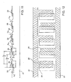
- the surface acoustic wave transducer comprises substrate 1 having a flat surface and positive and negative electrodes disposed on the flat surface of substrate 1, the positive and negative electrodes constituting an IDT (interdigital transducer).
- the positive and negative electrodes excite a surface acoustic wave and receive a propagated surface acoustic wave.
- the positive electrode comprises extracting electrode (i.e., bus bar) 2 extending along one side of substrate 1 and a plurality of electrode fingers 5 branched from extracting electrode 2.
- the negative electrode comprises extracting electrode 3 extending along the other side of substrate 1 and a plurality of electrode fingers 6 branched from extracting electrode 3.
- Substrate 1 comprises a substrate made of a piezoelectric or electrostrictive material or a substrate having a thin piezoelectric film on its surface.
- the surface acoustic wave transducer also has a plurality of dielectric films 4 in the form of rectangular strips, each having a width "a" of ⁇ 0 /4, for example, disposed on the surface of substrate 1 in a repetitive pattern at periodic intervals of ⁇ 0 /2 along the propagating direction of surface acoustic waves.
- Each of dielectric films 4 extends in the direction in which positive and negative electrode fingers 5, 6 extend.
- Dielectric films 4 have a film thickness of H 1 .
- Dielectric films 4 may be in the form of thin films of SiO 2 , SiO, ZnO, LiNbO 3 , Ta 2 O 5 , PZT (lead zirconate titanate), or glass.
- electrode fingers 5 of the positive electrode and electrode fingers 6 of the negative electrodes are alternately disposed at periodic intervals of ⁇ 0 /2 thereby constituting an IDT structure.
- Electrode fingers 5 of the positive electrode are arranged at periodic intervals of ⁇ 0
- electrode fingers 6 of the negative electrode arranged at periodic intervals ⁇ 0 .
- those electrode fingers are arranged at periodic intervals ⁇ 0 /2 as electric fingers of the IDT structure.
- These electrode fingers have a film thickness of H 2 and a width "b" which is typically ⁇ 0 /4.
- Dielectric films 4 are associated with respective positive and negative electrode fingers 5, 6, which are disposed over both the exposed surface of substrate 1 and dielectric films 4 such that they have partial transverse areas positioned on dielectric films 4.
- the positions of central lines of respective dielectric films 4 and the positions of central lines of respective electrode fingers 5, 6 which are paired with those dielectric films are displaced from each other by a distance x 1 in the propagating direction of surface acoustic waves.
- the distance x 1 is typically equal to ⁇ 0 /8.
- the surface acoustic wave transducer can be made by patterning dielectric films 4 on the surface of substrate 1, and then patterning electrode fingers 5, 6 on the assembly using a mask, at positions displaced from corresponding dielectric films 4 by the distance x 1 .
- Dielectric films 4 may be replaced with metal films.
- metal films of Al, Cu, Mo, Au, Ag, W, Ti or an alloy thereof can be used.
- the surface acoustic wave transducer can be manufactured simply by forming an IDT of a normal structure according to a mask alignment exposure process on the surface of substrate 1 with dielectric films 4 or metal films disposed thereon. According to the present embodiment, therefore, the internal-reflection-type unidirectional surface acoustic wave transducer can be manufactured by a simple fabrication process.
- the surface acoustic wave transducer according to the present embodiment causes a low loss and is compatible with high frequencies because it does not need a phase shifter and has its electrode fingers whose width is not ⁇ 0 /8.
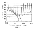
- FIG. 3 shows an insertion loss determined by a simulation calculating process of a filter having two unidirectional surface acoustic wave transducers shown in FIGS. 1 and 2 which are disposed in confronting relation to each other on a 128°-rotated Y-cut X-propagating LiNbO 3 substrate when one of the unidirectional surface acoustic wave transducers excites a surface acoustic wave and the other unidirectional surface acoustic wave transducer receives the surface acoustic wave propagated thereto.
- the width "a" of dielectric films 4, the width "b” of positive and negative electrode fingers 5, 6, and the distance x 1 between the centers of dielectric films 4 and the centers of electrode fingers 5, 6 are not limited to the values described above. lf the width "a” of dielectric films 4 is varied in the range from 0.05 ⁇ 0 to 0.5 ⁇ 0 , the film thickness H 1 of dielectric films 4 is varied in the range from 0.001 ⁇ 0 to 0.3 ⁇ 0 , the film thickness H 2 of positive and negative electrode fingers 5, 6 is varied in the range from 0.001 ⁇ 0 to 0.3 ⁇ 0 , the width "b” of positive and negative electrode fingers 5, 6 is varied in the range from 0.05 ⁇ 0 to 0.5 ⁇ 0 , and the distance x 1 between the centers of dielectric films 4 and the centers of electrode fingers 5, 6 is varied in the range from -0.25 ⁇ 0 to 0.25 ⁇ 0 , then it is possible to obtain surface acoustic wave transducers of the IDT type having various characteristics.
- Each of electrode fingers 5, 6 may be of a double electrode structure, with one of them being positioned on dielectric films 4 and the other directly on the surface of substrate 1.
- a surface acoustic wave transducer according to a second embodiment of the present invention will be described below with reference to FIGS. 4 and 5.
- the surface acoustic wave transducer according to the second embodiment is a mass-loading-changing-type unidirectional surface acoustic wave transducer which differs from the surface acoustic wave transducer according to the first embodiment in that the dielectric films and the electrode fingers on the substrate thereof are vertically inverted in position.
- the surface acoustic wave transducer comprises substrate 1 having a flat surface and positive and negative electrodes as an IDT disposed on the flat surface of substrate 1.
- the positive and negative electrodes excite a surface acoustic wave and receive a propagated surface acoustic wave.
- the positive electrode comprises extracting electrode 2 extending along one side of substrate 1 and a plurality of electrode fingers 7 branched from extracting electrode 2.
- the negative electrode comprises extracting electrode 3 extending along the other side of substrate 1 and a plurality of electrode fingers 9 branched from extracting electrode 3.
- electrode fingers 7, 9 have a film thickness of H 3 and are disposed directly on the surface of substrate 1.
- Electrode fingers 7, 9 are alternately disposed at periodic intervals of ⁇ 0 /2 as electrode fingers of the IDT structure and have a width "c" which is typically ⁇ 0 /4.
- Dielectric films 8 are associated with respective electrode fingers 7, 9.
- the positions of central lines of respective positive and negative electrode fingers 7, 9 and the positions central lines of dielectric films 8 that are paired with those electrode fingers are displaced from each other by a distance x 2 in the propagating direction of surface acoustic waves.
- the distance x 2 is typically equal to ⁇ 0 /8.
- the surface acoustic wave transducer of the IDT type can be made by forming positive and negative electrodes of an IDT of a normal structure on the surface of substrate 1, and then forming dielectric films 8 on the assembly according to a mask alignment exposure process, at positions displaced from corresponding positive and negative electrode fingers 7, 9 by the distance x 2 .
- the unidirectional surface acoustic wave transducer causes a low loss, is compatible with high frequencies, and can be manufactured by a simple fabrication process.
- Dielectric films 8 may be replaced with metal films which may be identical to those described in the first embodiment.
- Dielectric films 8 may be identical to dielectric films 4 of the surface acoustic wave transducer according to the first embodiment.
- the width "c" of positive and negative electrode fingers 7, 9 is varied in the range from 0.05 ⁇ 0 to 0.5 ⁇ 0
- the film thickness H 3 of positive and negative electrode fingers 7, 9 is varied in the range from 0.001 ⁇ 0 to 0.3 ⁇ 0
- the width "d" of dielectric films 8 is varied in the range from 0.05 ⁇ 0 to 0.5 ⁇ 0
- the film thickness H 4 of dielectric films 8 is varied in the range from 0.001 ⁇ 0 to 0.3 ⁇ 0
- the distance x 2 between the centers of dielectric films 8 and the centers of electrode fingers 7, 9 is varied in the range from -0.25 ⁇ 0 to 0.25 ⁇ 0 , then it is possible to obtain surface acoustic wave transducers having various characteristics.
- Each of electrode fingers 7, 9 may be of a double electrode structure, with dielectric films 8 being disposed on one of them and no dielectric films on the other.
- a surface acoustic wave transducer according to a third embodiment of the present invention will be described below with reference to FIGS. 6 and 7.
- the surface acoustic wave transducer according to the third embodiment is a mass-loading-changing-type unidirectional surface acoustic wave transducer, but differs therefrom in that dielectric film 10 is disposed in covering relation to the entire surface of substrate 1 and electrode fingers 7, 9 formed on substrate 1. The thickness of dielectric film 10 is modulated to provide a mass loading changing effect.
- a positive electrode having extracting electrode 2 and a plurality of electrode fingers 7, and a negative electrode having extracting electrode 3 and a plurality of electrode fingers 8 are disposed on a flat surface of substrate 1 having the flat surface.
- the positive and negative electrodes constitutes an IDT.
- Electrode fingers 7, 9 are alternately disposed in the propagating direction of surface acoustic waves at periodic intervals of ⁇ 0 /2, and have a width "e" which is typically ⁇ 0 /4.
- Dielectric film 10 is disposed on the exposed surface of substrate 1 in covering relation to the entire surface of the positive and negative electrodes.
- Dielectric film 10 has, defined in its surface, grooves in the shape of rectangular strips extending in the direction in which electrode fingers 7, 9 extend and disposed at periodic intervals of ⁇ 0 /4 in the propagating direction of surface acoustic waves.
- the grooves have a depth H 6 and a width "f" which is typically ⁇ 0 /4.
- the position of central lines of the respective grooves and the position central lines of respective electrode fingers 7, 9 which are paired with those grooves are displaced from each other by a distance x 3 in the propagating direction of surface acoustic waves.
- the distance x 3 is typically equal to ⁇ 0 /8.
- a process of manufacturing the surface acoustic wave transducer shown in FIGS. 6 and 7 will be described below.
- Positive and negative electrodes are formed on the surface of substrate 1, and dielectric film 10 is then formed on the surface of substrate 1 over the electrodes.
- dielectric film 10 has a flat upper surface, and a film thickness H 6 in areas free of electrode fingers. Thereafter, grooves are formed to the thickness H 6 in the surface of dielectric film 10 by etching.
- a dielectric film having a flat surface may be formed and then dielectric films in the form of rectangular strips, each having a width "f" and a thickness H 7 , may be formed on the previously formed dielectric film.
- FIG. 8 shows such a modified surface acoustic wave transducer. ln FIG. 8, the rectangular strips of dielectric film 10 are disposed in a repetitive pattern at periodic intervals of ⁇ 0 /2 along the propagating direction of surface acoustic waves.
- the dielectric film whose surface is flat has a thickness H 5 in areas free of electrode fingers.
- the surface acoustic wave transducer shown in FIGS. 6 and 7 and the modified surface acoustic wave transducer shown in FIG. 8 can be manufactured using at least two masks by an exposure process that is carried out twice or more or an electron beam superposed exposure process. According to the present embodiment, it is possible to obtain a unidirectional surface acoustic wave transducer which causes a low loss, is compatible with high frequencies, and can be manufactured by a simple fabrication process.
- Dielectric film 10 may be identical to dielectric films 8 in the surface acoustic wave transducer according to the second embodiment.
- the width "e” of positive and negative electrode fingers 7, 9 is varied in the range from 0.05 ⁇ 0 to 0.5 ⁇ 0
- the film thickness of positive and negative electrode fingers 7, 9 is varied in the range from 0.001 ⁇ 0 to 0.3 ⁇ 0
- the width "f" of the grooves etched in dielectric film 10 or the width "f” of the rectangular strips of the dielectric film mounted on the flat dielectric film is varied in the range from 0.05 ⁇ 0 to 0.5 ⁇ 0
- the depth H 6 of the grooves or the thickness H 7 of the rectangular strips is varied in the range from 0.001 ⁇ 0 to 0.3 ⁇ 0
- the distance x 3 between the centers of the grooves in dielectric film 10 or the rectangular strips and the centers of electrode fingers 7, 9 is varied in the range from -0.25 ⁇ 0 to 0.25 ⁇ 0 , then it is possible to obtain interdigital surface acoustic wave transducers having various characteristics.
- the periodic intervals of the electrode fingers and the dielectric films do not necessarily need to be exactly ⁇ 0 /2.
- the present invention is applicable to a dispersive surface acoustic wave transducer where the periodic intervals are progressively greater or smaller away from ⁇ 0 /2 according to a constant rule.
- a surface acoustic wave transducer according to a fourth embodiment of the present invention will be described below with reference to FIGS. 9 and 10.
- the surface acoustic wave transducer according to the fourth embodiment is similar to the electromechanical-coupling-constant-changing-type unidirectional surface acoustic wave transducer according to the first embodiment, except that dielectric films 4 in the form of rectangular strips and electrode fingers 5, 6 overlap differently with respect to respective electrode fingers 5, 6, and electrode fingers 5, 6 are weighted accordingly. Specifically, whereas the electrode fingers are spaced at constant periodic intervals of ⁇ 0 /2, dielectric films 4 are spaced at periodic intervals that vary from position to position.
- the central positions of the electrode fingers and the central positions of the dielectric films are displaced substantially ⁇ 0 /4 in a central area of the surface acoustic wave transducer, but the electrode fingers and the dielectric films substantially fully overlap each other at opposite ends of the surface acoustic wave transducer. Since the electromechanical coupling constant is smaller as the overlapping area of the dielectric films and the electrode fingers is greater, the electrode fingers are weighted greatly in the central area of the surface acoustic wave transducer. Dielectric films 4 are shifted to the left in FIG. 9 from the corresponding electrode fingers except at the opposite ends of the surface acoustic wave transducer, the surface acoustic wave transducer is kept unidirectional.
- the surface acoustic wave transducer can be manufactured by forming dielectric films 4 on substrate 1 and then forming positive and negative electrode fingers 5, 6 according to a mask alignment process using two masks or more or an electron beam double exposure process.
- the above weighting scheme is also applicable to the surface acoustic wave transducer according to the second embodiment shown in FIGS. 4 and 5. Specifically, the amount by which the electrode fingers and dielectric films 8 disposed thereon overlap each other may be varied.
- the present embodiment it is possible to keep the surface acoustic wave transducer unidirectional and also to vary the amount by which the electrode fingers and the dielectric films overlap each other for thereby weighting the electromechanical coupling constant. Accordingly, surface acoustic wave transducers and filters of excellent characteristics can be obtained. According to the present embodiment, in particular, because the electromechanical coupling constant can be weighted with the width of the electrode fingers being kept unchanged and with the periodic intervals of the electrode fingers being kept constant, it is possible to achieve filters of desired characteristics with a reduced weighting loss.
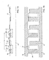
- a surface acoustic wave transducer will be described below with reference to FIGS. 11 and 12.
- the dielectric films in the form of rectangular strips are disposed at periodic intervals on the upper surface of the flat substrate.
- grooves 24 in the form of rectangular strips are defined at periodic intervals in the surface of substrate 21, providing an impedance-changing-type unidirectional surface acoustic wave transducer for propagating a surface acoustic wave only in one direction.
- the surface acoustic wave transducer comprises substrate 21, a plurality of grooves 24 in the form of rectangular strips which are defined at periodic intervals in the surface of substrate 21, and positive and negative electrodes on the surface of substrate 21 including the positions of grooves 24, the positive and negative electrodes constituting an IDT.
- the positive and negative electrodes excite a surface acoustic wave and receive the propagated surface acoustic wave.
- the positive electrode comprises extracting electrode 22 extending along one side of substrate 21 and a plurality of electrode fingers 25 branched from extracting electrode 22.
- the negative electrode comprises extracting electrode 23 extending along the other side of substrate 21 and a plurality of electrode fingers 26 branched from extracting electrode 23.
- Electrode fingers 25 of the positive electrode and electrode fingers 26 of the negative electrodes are alternately disposed at periodic intervals of ⁇ 0 /2 as electrode fingers of the IDT structure.
- Substrate 21 comprises a substrate made of a piezoelectric or electrostrictive material or a substrate having a thin piezoelectric film on its surface.
- Grooves 24 defined in the surface of substrate 21 extend in the direction in which electrode fingers 25, 26 extend and are disposed at periodic intervals of ⁇ 0 /2 in the propagating direction of surface acoustic waves. Grooves 24 have a depth H 11 and a width "g" which is typically ⁇ 0 /4. Each of electrode fingers 25, 26 has a thickness H 22 and a width "h" which is typically ⁇ 0 /4. Therefore, grooves 24 are associated with the respective electrode fingers.
- Each of electrode fingers 25, 26 lies across and over one longitudinal side of one of grooves 24, and has a transverse area positioned on the bottom of groove 24 and a remaining transverse area outside groove 24.
- the positions of central lines of respective grooves 24 and the positions of central lines of respective electrode fingers 25, 26 which are paired with those dielectric films are displaced from each other by a distance x 4 in the propagating direction of surface acoustic waves.
- the distance x 4 is typically equal to ⁇ 0 /8.
- the surface acoustic wave transducer can be manufactured by preparing substrate 21 having a flat surface, forming grooves 24 in the surface of substrate 21 by etching or the like, and forming positive and negative electrodes according to a mask alignment exposure process on the surface of substrate 21 such that the central positions of grooves 24 and the central positions of the electrode fingers are displaced from each other by the distance x 4 .
- the surface acoustic wave transducer propagates a surface acoustic wave in one direction based on the difference between the impedance in grooves 24 and the impedance on the surface of substrate 21.
- the internal-reflection-type unidirectional surface acoustic wave transducer can be manufactured by a simple fabrication process.
- the surface acoustic wave transducer according to the present embodiment causes a low loss and is compatible with high frequencies because it does not need a phase shifter and has its electrode fingers whose width is not ⁇ 0 /8.
- FIG. 13 shows an insertion loss determined by a simulation calculating process of a filter having two unidirectional surface acoustic wave transducers shown in FIGS. 11 and 12 which are disposed in confronting relation to each other on a 128°-rotated Y-cut X-propagating LiNbO 3 substrate.
- a low insertion loss is achieved, i.e., a forward insertion loss of 0.7 dB is achieved, as indicated by the curve 34 in FIG. 13.
- the two unidirectional surface acoustic wave transducers are oriented back to back (i.e., in backward), a large insertion loss of 23 dB is achieved as indicated by the curve 35 in FIG. 13.
- the width "g" of grooves 24 is varied in the range from 0.05 ⁇ 0 to 0.5 ⁇ 0
- the depth H 11 of grooves 24 is varied in the range from 0.001 ⁇ 0 to 0.3 ⁇ 0
- the film thickness H 12 of positive and negative electrode fingers 25, 26 is varied in the range from 0.001 ⁇ 0 to 0.3 ⁇ 0
- the width "h” of positive and negative electrode fingers 25, 26 is varied in the range from 0.05 ⁇ 0 to 0.5 ⁇ 0
- the distance x 4 between the center positions of grooves 24 and the center positions of electrode fingers 25, 26 is varied in the range from -0.25 ⁇ 0 to 0.25 ⁇ 0 , then it is possible to obtain unidirectional interdigital surface acoustic wave transducers having various characteristics.
- Each of electrode fingers 25, 26 may be of a double electrode structure, with one of them being positioned on the bottom of grooves 24 and the other directly on the surface of substrate 21.
- a surface acoustic wave transducer according to a sixth embodiment of the present invention will be described below with reference to FIGS. 14 and 15.
- the surface acoustic wave transducer according to the sixth embodiment is similar to the surface acoustic wave transducer according to the fifth embodiment, except that the grooves are defined in the surface of substrate 21 at greater periodic intervals of ⁇ 0 .
- the surface acoustic wave transducer thus arranged according to the sixth embodiment serves as a susceptance-changing-type unidirectional surface acoustic wave transducer.
- the surface acoustic wave transducer comprises substrate 21, positive and negative electrodes disposed on the surface of substrate 21, and a plurality of grooves 27 defined in the surface of substrate 21.
- the positive electrode comprises extracting electrode 22 extending along one side of substrate 21 and a plurality of electrode fingers 28 branched from extracting electrode 22.
- the negative electrode comprises extracting electrode 23 extending along the other side of substrate 21 and a plurality of electrode fingers 29 branched from extracting electrode 23.
- Grooves 27 are disposed at periodic intervals of ⁇ 0 in the propagating direction of surface acoustic waves. Grooves 27 have a depth H 23 and a width "j" which is typically ⁇ 0 /2.
- Electrode fingers 28, 29 have a thickness H 24 and are alternately disposed at periodic intervals of ⁇ 0 /2. Electrode fingers 28, 29 have a width "i" which is typically ⁇ 0 /4. Therefore, each of grooves 27 is associated with one positive electrode finger 28 and one negative electrode finger 29.
- the electrode fingers are positioned such that the central positions of one type of electrode fingers, i.e., positive electrode fingers 28 in the illustrated embodiment, and the central positions of grooves 27 associated therewith are displaced from each other by a distance x 5 .
- the distance x 5 is typically ⁇ 0 /8.
- Positive electrode fingers 28 are disposed on the bottom of grooves 27 in contact with longitudinal sides of grooves 27, and negative electrode fingers 29 are disposed on the upper surface of substrate 21 in contact with the other longitudinal sides of grooves 27.
- the susceptance which appears at steps which are produced by forming grooves 27 is employed to realize an internal-reflection-type unidirectional surface acoustic wave transducer.
- the surface acoustic wave transducer can be manufactured by forming groove 27 in substrate 21 and thereafter forming the positive and negative electrodes in desired positions by a mask alignment exposure process.
- a unidirectional surface acoustic wave transducer which causes a low loss, is compatible with high frequencies, and can be manufactured by a simple fabrication process.
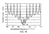
- FIG. 16 shows an insertion loss determined by a simulation calculation of a filter having two unidirectional surface acoustic wave transducers shown in FIGS. 14 and 15 which are disposed in confronting relation to each other on a Y-cut Z-propagating LiNbO 3 substrate.
- a low insertion loss is achieved, i.e., a forward insertion loss of 1.0 dB is achieved, as indicated by the curve 36 in FIG. 16.
- a large insertion loss of 22 dB is achieved as indicated by the curve 37 in FIG. 16.
- the width "j" of grooves 27 is varied in the range from 0.25 ⁇ 0 to 0.75 ⁇ 0
- the depth H 23 of grooves 27 is varied in the range from 0.001 ⁇ 0 to 0.3 ⁇ 0
- the film thickness H 24 of positive and negative electrode fingers 28, 29 is varied in the range from 0.001 ⁇ 0 to 0.3 ⁇ 0
- the width "i" of positive and negative electrode fingers 28, 29 is varied in the range from 0,05 ⁇ 0 to 0.5 ⁇ 0
- the distance x 5 is varied in the range from -0.25 ⁇ 0 to 0.25 ⁇ 0
- Electrode fingers 28, 29 may be formed after a dielectric film of SiO 2 or the like is applied to grooves 27.
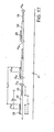
- a surface acoustic wave transducer according to a seventh embodiment of the present invention will be described below with reference to FIG. 17. ln the surface acoustic wave transducer according to the sixth embodiment, grooves 27 are defined in the surface of substrate 21. According to the seventh embodiment, however, thin films spaced at periodic intervals of ⁇ 0 and having a width "j" and a film thickness H 25 are disposed on the surface of the substrate.
- FIG. 17 shows a susceptance-changing-type unidirectional surface acoustic wave transducer having such thin films 30 according to the seventh embodiment.
- the width "j" is typically ⁇ 0 /2 as with the sixth embodiment.
- positive electrode fingers 28 are disposed on the upper surface of thin films 30 in contact with longitudinal sides of thin films 30, and negative electrode fingers 29 are disposed on the upper surface of substrate 21 in contact with the other longitudinal sides of thin films 30.
- Thin films 30 may comprise dielectric films of fused quartz, glass, Al 2 O 3 , or the like.
- the susceptance which appears at steps which are produced by forming thin films 30 is employed to realize an internal-reflection-type unidirectional surface acoustic wave transducer.
- the width "j" of thin films 30 is varied in the range from 0.25 ⁇ 0 to 0.75 ⁇ 0
- the film thickness H 25 of thin films 30 is varied in the range from 0.001 ⁇ 0 to 0.3 ⁇ 0
- the film thickness H 24 of positive and negative electrode fingers 28, 29 is varied in the range from 0.001 ⁇ 0 to 0.3 ⁇ 0
- the width "i" of positive and negative electrode fingers 28, 29 is varied in the range from 0.05 ⁇ 0 to 0.5 ⁇ 0
- the distance x 5 is varied in the range from -0.25 ⁇ 0 to 0.25 ⁇ 0
- a surface acoustic wave transducer according to an eighth embodiment of the present invention will be described below with reference to FIGS. 18 and 19.
- the surface acoustic wave transducer according to the eighth embodiment is constructed as a susceptance-changing-type unidirectional surface acoustic wave transducer which is provided by inverting the vertical relationship between the thin films and the electrode fingers on the substrate of the surface acoustic wave transducer according to the seventh embodiment.
- the surface acoustic wave transducer comprises substrate 21 having a flat surface and positive and negative electrodes disposed on the surface of substrate 21.
- the positive electrode comprises extracting electrode 22 extending along one side of substrate 21 and a plurality of electrode fingers 31 branched from extracting electrode 22.
- the negative electrode comprises extracting electrode 23 extending along the other side of substrate 21 and a plurality of electrode fingers 32 branched from extracting electrode 23.
- Electrode fingers 31, 32 have a film thickness H 24 and are directly disposed on the surface of substrate 21.
- Positive and negative electrode fingers 31, 32 are alternately disposed at periodic intervals of ⁇ 0 /2 as electrode fingers and have a width "j" which is typically ⁇ 0 /4.
- Thin films 33 having a width "j" which is typically ⁇ 0 /2 and a film thickness H 25 are disposed at periodic intervals ⁇ 0 in the propagating direction of surface acoustic waves so as to cover substrate 21 and electrode fingers 31, 32 in a regular pattern.
- Thin films 33 may be identical to thin films 30 according to the seventh embodiment.
- the susceptance which appears at steps which are produced by forming thin films 33 is employed to realize an internal-reflection-type unidirectional surface acoustic wave transducer.
- the above surface acoustic wave transducer can be manufactured by forming positive and negative electrodes of a normal structure on the surface of substrate 21 and applying thin films 33 thereto according to a mask alignment exposure process.
- Thin films 33 may be made of the same material as the material of the thin films of the surface acoustic wave transducer according to the seventh embodiment.
- the width "j" of thin films 33 is varied in the range from 0.25 ⁇ 0 to 0.75 ⁇ 0
- the film thickness H 25 of thin films 33 is varied in the range from 0.001 ⁇ 0 to 0.3 ⁇ 0
- the film thickness H 24 of positive and negative electrode fingers 31, 32 is varied in the range from 0.001 ⁇ 0 to 0.3 ⁇ 0
- the width "i" of positive and negative electrode fingers 31, 32 is varied in the range from 0.05 ⁇ 0 to 0.5 ⁇ 0
- the distance x 6 is varied in the range from -0.25 ⁇ 0 to 0.25 ⁇ 0 , then it is possible to obtain unidirectional interdigital surface acoustic wave transducers having various characteristics.
- the periodic intervals of the electrode fingers, the periodic intervals of the grooves, and the periodic intervals of the thin films do not necessarily need to be exactly ⁇ 0 /2 or ⁇ 0 . These periodic intervals may be varied from those values.
- the present invention is applicable to a dispersive surface acoustic wave transducer where the periodic intervals are varied according to a constant rule.
- the electrodes in the IDT structure are made of a metal such as Al, Cu, Mo, Au, Ag, W, Ti or an alloy thereof.
- Each of the IDT electrodes may be of a double electrode structure.
- the substrate of the surface acoustic wave transducers is made of a piezoelectric or electrostrictive material, the substrate may preferably be made of quartz crystal, single crystal of langasites, single crystal of Li 2 B 4 O 7 , single crystal of Bi 12 GeO 20 , single crystal of Bi 12 SiO 20 , single crystal of LiNbO 3 , single crystal of LiTaO 3 , single crystal of KNbO 3 , or PZT.
- the thin piezoelectric film may preferably be made of ZnO, AlN, LiTaO 3 , LiNbO 3 , KNbO 3 , Ta 2 O 5 , or PZT.
- a dielectric film made of a thin film of SiO 2 having a film thickness in the range from 0.05 ⁇ 0 to 0.5 ⁇ 0 or a dielectric film made of glass having positive frequency-temperature characteristics may be applied to the surface of the surface acoustic wave transducer according to each of the above embodiments.
- the internal-reflection-type unidirectional surface acoustic wave transducer includes an internal-reflection-type unidirectional surface acoustic wave transducer which operates at a frequency N ⁇ 0 where N represents an integer of 1 or more and ⁇ 0 a fundamental operating angular frequency at a wavelength ⁇ 0 .
- unidirectional surface acoustic wave transducers according to the present invention are disposed in facing relation (i.e., "forward") to each other and have IDT electrodes arranged in phase with each other, then a surface acoustic wave resonator having good characteristics is obtained. If reflectors are provided on propagation paths on both sides of the surface acoustic wave transducers of the surface acoustic wave resonator, then a surface acoustic wave resonator having better characteristics with a large reflection coefficient is obtained. These resonators should be interpreted as falling within the scope of attached claims.
Landscapes
- Physics & Mathematics (AREA)
- Acoustics & Sound (AREA)
- Surface Acoustic Wave Elements And Circuit Networks Thereof (AREA)
Applications Claiming Priority (4)
| Application Number | Priority Date | Filing Date | Title |
|---|---|---|---|
| JP2003137987 | 2003-04-08 | ||
| JP2003137987A JP4385277B2 (ja) | 2003-04-08 | 2003-04-08 | 弾性表面波変換器とこれを用いた電子装置 |
| JP2003200799A JP2005012736A (ja) | 2003-06-17 | 2003-06-17 | 弾性表面波変換器とこれを用いた電子装置 |
| JP2003200799 | 2003-06-17 |
Publications (1)
| Publication Number | Publication Date |
|---|---|
| EP1467484A2 true EP1467484A2 (fr) | 2004-10-13 |
Family
ID=32871264
Family Applications (1)
| Application Number | Title | Priority Date | Filing Date |
|---|---|---|---|
| EP04008539A Withdrawn EP1467484A2 (fr) | 2003-04-08 | 2004-04-08 | Transducteur à ondes acoustiques de surface |
Country Status (2)
| Country | Link |
|---|---|
| US (1) | US7135805B2 (fr) |
| EP (1) | EP1467484A2 (fr) |
Cited By (4)
| Publication number | Priority date | Publication date | Assignee | Title |
|---|---|---|---|---|
| WO2007099742A1 (fr) | 2006-03-02 | 2007-09-07 | Murata Manufacturing Co., Ltd. | Dispositif d'onde acoustique et procede de fabrication correspondant |
| WO2012110377A1 (fr) * | 2011-02-16 | 2012-08-23 | Epcos Ag | Composant fonctionnant avec des ondes acoustiques et procédé de fabrication correspondant |
| WO2013083469A3 (fr) * | 2011-12-06 | 2013-09-12 | Leibniz-Institut Für Festkörper- Und Werkstoffforschung Dresden E.V. | Élément à ondes acoustiques de surface et procédé de fabrication correspondant |
| WO2019096015A1 (fr) * | 2017-11-15 | 2019-05-23 | Huawei Technologies Co., Ltd. | Dispositif à ondes acoustiques de surface |
Families Citing this family (19)
| Publication number | Priority date | Publication date | Assignee | Title |
|---|---|---|---|---|
| US7053523B1 (en) * | 2004-02-02 | 2006-05-30 | The United States Of America As Represented By The Secretary Of The Army | Lateral field excitation of bulk acoustic waves from an IC-compliant low voltage source |
| TW200626893A (en) * | 2005-01-28 | 2006-08-01 | yong-yu Chen | Surface acoustic wave thin-film measuring device and measuring method thereof |
| JP4692629B2 (ja) * | 2006-05-30 | 2011-06-01 | 株式会社村田製作所 | 弾性波装置 |
| CN101796724B (zh) * | 2007-12-17 | 2013-06-19 | 太阳诱电株式会社 | 弹性波元件、通信组件、以及通信装置 |
| US7939987B1 (en) * | 2008-10-23 | 2011-05-10 | Triquint Semiconductor, Inc. | Acoustic wave device employing reflective elements for confining elastic energy |
| JP4645923B2 (ja) * | 2009-02-27 | 2011-03-09 | セイコーエプソン株式会社 | 弾性表面波共振子、および弾性表面波発振器 |
| US8952596B2 (en) * | 2009-02-27 | 2015-02-10 | Seiko Epson Corporation | Surface acoustic wave resonator, surface acoustic wave oscillator, and electronic instrument |
| US8280080B2 (en) * | 2009-04-28 | 2012-10-02 | Avago Technologies Wireless Ip (Singapore) Pte. Ltd. | Microcap acoustic transducer device |
| JP5678486B2 (ja) | 2010-06-17 | 2015-03-04 | セイコーエプソン株式会社 | 弾性表面波共振子、弾性表面波発振器および電子機器 |
| JP5934464B2 (ja) | 2010-08-26 | 2016-06-15 | セイコーエプソン株式会社 | 弾性表面波共振子、および弾性表面波発振器、ならびに電子機器 |
| JP2012049817A (ja) | 2010-08-26 | 2012-03-08 | Seiko Epson Corp | 弾性表面波デバイス、および弾性表面波発振器、ならびに電子機器 |
| JP2012049818A (ja) | 2010-08-26 | 2012-03-08 | Seiko Epson Corp | 弾性表面波共振子、弾性表面波発振器、電子機器 |
| JP2012060420A (ja) | 2010-09-09 | 2012-03-22 | Seiko Epson Corp | 弾性表面波デバイス、電子機器及びセンサー装置 |
| JP5652606B2 (ja) | 2010-12-03 | 2015-01-14 | セイコーエプソン株式会社 | 弾性表面波共振子、弾性表面波発振器、及び電子機器 |
| JP5648908B2 (ja) | 2010-12-07 | 2015-01-07 | セイコーエプソン株式会社 | 振動デバイス、並びに発振器、および電子機器 |
| KR101705973B1 (ko) * | 2015-04-22 | 2017-02-13 | 연세대학교 산학협력단 | 유전체 전자기파 차폐막 |
| DE102016105118A1 (de) * | 2016-03-18 | 2017-09-21 | Snaptrack, Inc. | SAW-Bauelement mit verringerten Störungen durch transversale und SH-Moden und HF-Filter mit SAW-Bauelement |
| US10700661B2 (en) * | 2018-01-19 | 2020-06-30 | Huawei Technologie Co., Ltd. | Surface acoustic wave device with unidirectional transducer |
| JP2020096226A (ja) * | 2018-12-10 | 2020-06-18 | 太陽誘電株式会社 | 弾性波デバイス、フィルタおよびマルチプレクサ |
Family Cites Families (13)
| Publication number | Priority date | Publication date | Assignee | Title |
|---|---|---|---|---|
| US4155057A (en) * | 1976-03-19 | 1979-05-15 | Raytheon Company | Surface acoustic wave ring filter |
| US4097825A (en) * | 1977-01-05 | 1978-06-27 | Hughes Aircraft Company | Surface acoustic wave tapped delay line |
| US4353046A (en) * | 1980-11-04 | 1982-10-05 | R F Monolithics, Inc. | Surface acoustic wave device with reflectors |
| US4454488A (en) * | 1982-07-08 | 1984-06-12 | R F Monolithics, Inc. | Surface acoustic wave resonator with middle grating |
| JPH0773177B2 (ja) * | 1984-12-17 | 1995-08-02 | 株式会社東芝 | 弾性表面波共振子 |
| GB2206257B (en) * | 1987-05-26 | 1991-08-14 | Clarion Co Ltd | Surface acoustic wave device |
| US5051644A (en) * | 1990-04-19 | 1991-09-24 | R. F. Monolithics, Inc. | Electrode structure with constant velocity and predetermined reflectivity |
| US5061871A (en) * | 1991-01-25 | 1991-10-29 | R. F. Monolithics, Inc. | Electrode structure with constant velocity and zero reflectivity |
| JPH06260881A (ja) * | 1992-07-24 | 1994-09-16 | Mitsui Mining & Smelting Co Ltd | 弾性表面波コンボルバ |
| US5406159A (en) * | 1993-11-11 | 1995-04-11 | Rf Monolithics, Inc. | Surface acoustic wave gratings having selected reflectivity |
| US5793146A (en) * | 1993-11-12 | 1998-08-11 | Rf Monolithics, Inc. | Surface acoustic wave transducer having selected reflectivity |
| JP3268179B2 (ja) * | 1995-11-08 | 2002-03-25 | 正男 竹内 | 弾性表面波変換器及びこの変換器を用いた弾性表面波フィルタ |
| FR2779289B1 (fr) * | 1998-05-29 | 2000-09-01 | Thomson Csf | Transducteur unidirectionnel grave a ondes acoustiques de surface |
-
2004
- 2004-04-07 US US10/819,814 patent/US7135805B2/en not_active Expired - Fee Related
- 2004-04-08 EP EP04008539A patent/EP1467484A2/fr not_active Withdrawn
Cited By (15)
| Publication number | Priority date | Publication date | Assignee | Title |
|---|---|---|---|---|
| US8677582B2 (en) | 2006-03-02 | 2014-03-25 | Murata Manufacturing Co., Ltd. | Method for fabricating acoustic wave device |
| EP1990915A1 (fr) * | 2006-03-02 | 2008-11-12 | Murata Manufacturing Co. Ltd. | Dispositif d'onde acoustique et procede de fabrication correspondant |
| EP1990915A4 (fr) * | 2006-03-02 | 2010-03-31 | Murata Manufacturing Co | Dispositif d'onde acoustique et procede de fabrication correspondant |
| WO2007099742A1 (fr) | 2006-03-02 | 2007-09-07 | Murata Manufacturing Co., Ltd. | Dispositif d'onde acoustique et procede de fabrication correspondant |
| US8810104B2 (en) | 2006-03-02 | 2014-08-19 | Murata Manufacturing Co., Ltd. | Acoustic wave device and method for fabricating the same |
| WO2012110377A1 (fr) * | 2011-02-16 | 2012-08-23 | Epcos Ag | Composant fonctionnant avec des ondes acoustiques et procédé de fabrication correspondant |
| CN103370875A (zh) * | 2011-02-16 | 2013-10-23 | 埃普科斯股份有限公司 | 利用声波工作的器件和制造的方法 |
| DE102011011377B4 (de) * | 2011-02-16 | 2016-05-25 | Epcos Ag | Mit akustischen Wellen arbeitendes Bauelement |
| US9455684B2 (en) | 2011-02-16 | 2016-09-27 | Epcos Ag | Component operating with acoustic waves and method for producing same |
| CN103370875B (zh) * | 2011-02-16 | 2016-10-12 | 埃普科斯股份有限公司 | 利用声波工作的器件和制造的方法 |
| WO2013083469A3 (fr) * | 2011-12-06 | 2013-09-12 | Leibniz-Institut Für Festkörper- Und Werkstoffforschung Dresden E.V. | Élément à ondes acoustiques de surface et procédé de fabrication correspondant |
| EP3232569A3 (fr) * | 2011-12-06 | 2017-12-13 | Leibnitz-Institut für Festkörper- und Werkstoffforschung Dresden e.V. | Élément de construction ondulé de surface acoustique et son procédé de fabrication |
| WO2019096015A1 (fr) * | 2017-11-15 | 2019-05-23 | Huawei Technologies Co., Ltd. | Dispositif à ondes acoustiques de surface |
| CN111316566A (zh) * | 2017-11-15 | 2020-06-19 | 华为技术有限公司 | 表面声波设备 |
| US11316495B2 (en) | 2017-11-15 | 2022-04-26 | Huawei Technologies Co., Ltd. | Surface acoustic wave device |
Also Published As
| Publication number | Publication date |
|---|---|
| US7135805B2 (en) | 2006-11-14 |
| US20040201306A1 (en) | 2004-10-14 |
Similar Documents
| Publication | Publication Date | Title |
|---|---|---|
| US7135805B2 (en) | Surface acoustic wave transducer | |
| KR102671258B1 (ko) | 공동 공진 saw 필터 | |
| JP2009177829A (ja) | 弾性境界波装置 | |
| US5977686A (en) | Surface acoustic wave filter | |
| JP2001077662A (ja) | 表面波装置及び通信機装置 | |
| JP3853252B2 (ja) | 弾性表面波素子 | |
| JP3414373B2 (ja) | 弾性表面波装置 | |
| JP2000183681A (ja) | 弾性表面波装置 | |
| US5294859A (en) | Surface acoustic wave filter device | |
| JP2005012736A (ja) | 弾性表面波変換器とこれを用いた電子装置 | |
| JP7519902B2 (ja) | Sawフィルタデバイスにおける発生源抑制のための変換器構造 | |
| JP6335492B2 (ja) | 弾性波素子 | |
| JP6333891B2 (ja) | 弾性表面波変換器、弾性表面波フィルタおよび弾性表面波フィルタの製造方法 | |
| JP4457914B2 (ja) | 一方向性弾性表面波変換器及びそれを用いた弾性表面波デバイス | |
| JP3442202B2 (ja) | 表面弾性波フィルタ | |
| EP3796555A1 (fr) | Structure de transducteur pour dispositif d'onde acoustique | |
| Hashimoto | Surface acoustic wave (SAW) devices | |
| JP4385277B2 (ja) | 弾性表面波変換器とこれを用いた電子装置 | |
| JP4158289B2 (ja) | 表面弾性波素子の製造方法 | |
| JP2010245738A (ja) | Sawフィルター | |
| JP2006060759A (ja) | 弾性表面波共振器とこれを用いた電子装置 | |
| JP4506394B2 (ja) | 一方向性弾性表面波変換器及びそれを用いた弾性表面波デバイス | |
| EP3796556A1 (fr) | Structure de transducteur pour dispositif d'onde acoustique | |
| JP2002223143A (ja) | 弾性表面波装置 | |
| JPH08213869A (ja) | インターディジタルトランスデューサ型弾性表面波共振子 |
Legal Events
| Date | Code | Title | Description |
|---|---|---|---|
| PUAI | Public reference made under article 153(3) epc to a published international application that has entered the european phase |
Free format text: ORIGINAL CODE: 0009012 |
|
| AK | Designated contracting states |
Kind code of ref document: A2 Designated state(s): AT BE BG CH CY CZ DE DK EE ES FI FR GB GR HU IE IT LI LU MC NL PL PT RO SE SI SK TR |
|
| AX | Request for extension of the european patent |
Extension state: AL HR LT LV MK |
|
| RAP1 | Party data changed (applicant data changed or rights of an application transferred) |
Owner name: NIHON DEMPA KOGYO CO., LTD. Owner name: YAMANOUCHI, KAZUHIKO |
|
| STAA | Information on the status of an ep patent application or granted ep patent |
Free format text: STATUS: THE APPLICATION IS DEEMED TO BE WITHDRAWN |
|
| 18D | Application deemed to be withdrawn |
Effective date: 20090505 |