EP1467184A2 - Winkelstellungsdetektor - Google Patents
Winkelstellungsdetektor Download PDFInfo
- Publication number
- EP1467184A2 EP1467184A2 EP03012601A EP03012601A EP1467184A2 EP 1467184 A2 EP1467184 A2 EP 1467184A2 EP 03012601 A EP03012601 A EP 03012601A EP 03012601 A EP03012601 A EP 03012601A EP 1467184 A2 EP1467184 A2 EP 1467184A2
- Authority
- EP
- European Patent Office
- Prior art keywords
- angular position
- permanent magnet
- magnetic flux
- rotor core
- stator core
- Prior art date
- Legal status (The legal status is an assumption and is not a legal conclusion. Google has not performed a legal analysis and makes no representation as to the accuracy of the status listed.)
- Withdrawn
Links
- 238000001514 detection method Methods 0.000 claims abstract description 156
- 230000004907 flux Effects 0.000 claims abstract description 153
- 239000011347 resin Substances 0.000 claims description 17
- 229920005989 resin Polymers 0.000 claims description 17
- 230000009467 reduction Effects 0.000 claims description 13
- 230000007246 mechanism Effects 0.000 claims description 12
- 230000005415 magnetization Effects 0.000 description 24
- 238000010586 diagram Methods 0.000 description 13
- 125000006850 spacer group Chemical group 0.000 description 9
- 230000007423 decrease Effects 0.000 description 8
- XEEYBQQBJWHFJM-UHFFFAOYSA-N Iron Chemical compound [Fe] XEEYBQQBJWHFJM-UHFFFAOYSA-N 0.000 description 6
- 230000008859 change Effects 0.000 description 6
- 239000000853 adhesive Substances 0.000 description 4
- 230000001070 adhesive effect Effects 0.000 description 4
- 239000000696 magnetic material Substances 0.000 description 4
- 238000000465 moulding Methods 0.000 description 4
- 230000005856 abnormality Effects 0.000 description 3
- 229910052742 iron Inorganic materials 0.000 description 3
- 238000004519 manufacturing process Methods 0.000 description 3
- 238000000034 method Methods 0.000 description 3
- 230000004048 modification Effects 0.000 description 3
- 238000012986 modification Methods 0.000 description 3
- 238000002485 combustion reaction Methods 0.000 description 2
- 238000004092 self-diagnosis Methods 0.000 description 2
- 238000009966 trimming Methods 0.000 description 2
- 238000003466 welding Methods 0.000 description 2
- 230000003321 amplification Effects 0.000 description 1
- 230000000694 effects Effects 0.000 description 1
- 238000003199 nucleic acid amplification method Methods 0.000 description 1
- 230000002093 peripheral effect Effects 0.000 description 1
Images


Classifications
-
- G—PHYSICS
- G01—MEASURING; TESTING
- G01D—MEASURING NOT SPECIALLY ADAPTED FOR A SPECIFIC VARIABLE; ARRANGEMENTS FOR MEASURING TWO OR MORE VARIABLES NOT COVERED IN A SINGLE OTHER SUBCLASS; TARIFF METERING APPARATUS; MEASURING OR TESTING NOT OTHERWISE PROVIDED FOR
- G01D5/00—Mechanical means for transferring the output of a sensing member; Means for converting the output of a sensing member to another variable where the form or nature of the sensing member does not constrain the means for converting; Transducers not specially adapted for a specific variable
- G01D5/12—Mechanical means for transferring the output of a sensing member; Means for converting the output of a sensing member to another variable where the form or nature of the sensing member does not constrain the means for converting; Transducers not specially adapted for a specific variable using electric or magnetic means
- G01D5/14—Mechanical means for transferring the output of a sensing member; Means for converting the output of a sensing member to another variable where the form or nature of the sensing member does not constrain the means for converting; Transducers not specially adapted for a specific variable using electric or magnetic means influencing the magnitude of a current or voltage
- G01D5/142—Mechanical means for transferring the output of a sensing member; Means for converting the output of a sensing member to another variable where the form or nature of the sensing member does not constrain the means for converting; Transducers not specially adapted for a specific variable using electric or magnetic means influencing the magnitude of a current or voltage using Hall-effect devices
- G01D5/145—Mechanical means for transferring the output of a sensing member; Means for converting the output of a sensing member to another variable where the form or nature of the sensing member does not constrain the means for converting; Transducers not specially adapted for a specific variable using electric or magnetic means influencing the magnitude of a current or voltage using Hall-effect devices influenced by the relative movement between the Hall device and magnetic fields
-
- F—MECHANICAL ENGINEERING; LIGHTING; HEATING; WEAPONS; BLASTING
- F02—COMBUSTION ENGINES; HOT-GAS OR COMBUSTION-PRODUCT ENGINE PLANTS
- F02D—CONTROLLING COMBUSTION ENGINES
- F02D11/00—Arrangements for, or adaptations to, non-automatic engine control initiation means, e.g. operator initiated
- F02D11/06—Arrangements for, or adaptations to, non-automatic engine control initiation means, e.g. operator initiated characterised by non-mechanical control linkages, e.g. fluid control linkages or by control linkages with power drive or assistance
- F02D11/10—Arrangements for, or adaptations to, non-automatic engine control initiation means, e.g. operator initiated characterised by non-mechanical control linkages, e.g. fluid control linkages or by control linkages with power drive or assistance of the electric type
- F02D11/106—Detection of demand or actuation
Definitions
- the present invention relates to angular position detection apparatuses, and particular to an angular position detection apparatuses containing a permanent magnet which is magnetized so that lines of magnetic force thereof are set parallel with each other.
- a stator core 12 is concentrically arranged at an inner side of a cylindrical rotor core 11, which integrally rotates with throttle valve (not-shown).
- Two permanent magnets 13 having circular arc are fixed to the inner side of the rotor core 11 so as to confront each other with sandwiching the stator core 12.
- Each of the permanent magnets 13 is radially magnetized so that all of lines of magnetic force in the permanent magnets 13 are set to a radial direction.
- directions of lines of magnetic forces in each of parts are illustrated by arrows ( ⁇ ).
- a magnetic flux detection gap portion 14 having a constant width is formed at a center portion of the stator core 12 so as to open along a diametral direction.
- a magnetic detection element 15 such as a Hall IC is provided in the magnetic flux detection gap portion 14.
- the output of the magnetic detection element 15 for detecting the angular position of the rotor core 11 changes in proportion to the magnetic flux density in the magnetic flux detection gap portion 14. Therefore, if the magnetic flux in the magnetic flux detection gap portion 14 linearly changes in proportion to the angular position of the rotor core 11, since an output characteristic of the magnetic detection element 15 regarding the angular position becomes linear, a detection characteristic of the angular position is improved.
- the permanent magnets 13 are arranged so as to confront with an outer surface of the stator core 12, an outer size of the rotor core 11 for fixing the permanent magnets 13 and therefore an outer size of the angular position detection apparatus becomes bulky.
- a density of the inner side of the permanent magnet 13 needs to be dense and a density of the outer side thereof needs to be coarse. Therefore, strength of the permanent magnet 13 is likely to decrease due to a difference in density.
- This invention has been conceived in view of the background thus far described and its first object is to provide an angular position detection apparatus in which a linearity of an output characteristic with respect to an angular position can be improved so as to improve a detection accuracy of the angular position.
- Its second object is to improve strength of a permanent magnet.
- Its third object is to downsize an outer size of the angular position detection apparatus.
- a permanent magnet is fixed to a side portion of a rotor core, so that the permanent magnet does not confront with an outer surface of a stator core.
- an outer size of the rotor core and therefore an outer size of the angular position detection apparatus can be downsized.
- the angular position detection apparatus is not formed as an axial gap type, but is formed as the radial gap type in which a cylindrical portion formed at the outer portion of the rotor core is closely confronted with the outer surface of the stator core, so that the magnetic flux is gone through the air gap between the cylindrical portion and the stator core along the radial direction.
- a dimension accuracy of the air gap can be also controlled, it can facilitate the control of the air gap.
- the permanent magnet since the permanent magnet is fixed to the side portion of the rotor core, the permanent magnet can be formed in a flat plate shape, and therefore it can facilitate the manufacture the permanent magnet.
- the permanent magnet is magnetized so that lines of the magnetic force in the permanent magnet are set to parallel each other (parallel magnetization).
- it can expand a range, in which the magnetic flux density in the magnetic flux detection gap portion of the stator core linearly changes in proportion to a rotation of the permanent magnet, compared to the radial magnetization as the related art.
- the parallel magnetization can make the density of the permanent magnet uniform, so that the strength of the permanent magnet can be increased.
- a throttle valve is rotated by an actuator such as a motor via a reduction mechanism, and an angular position of the actuator is detected by an angular position apparatus so that an angular position of the throttle valve (throttle opening degree).
- an actuator such as a motor via a reduction mechanism
- an angular position of the actuator is detected by an angular position apparatus so that an angular position of the throttle valve (throttle opening degree).
- throttle opening degree is calculated by dividing a detected value of the actuator by a reduction ratio of the reduction mechanism, a detection error of the throttle opening degree becomes large due to a variation of the reduction ratio or backlash (backlash) between gears.
- an electrical throttle system in which an angular position detection apparatus is externally provided on a extended line of a rotational shaft of the throttle valve, and a tip of the rotation shaft of the throttle valve is connected to a rotor in the angular position detection apparatus, so that the angular position of the throttle valve (throttle opening degree) is directly detected.
- the angular position detection apparatus is provided at outer side of the cover, which covers the reduction mechanism, entire system may be bulky.
- a rotation resistance of a bearing which supports the rotor in the angular position detection apparatus, acts to the rotation shaft of the throttle valve.
- the rotation resistance of the throttle valve becomes large, and therefore the load of the actuator becomes large.
- a permanent magnet may be fixed to a rotation shaft of the rotating body such as a throttle valve, a magnetic detection element for detecting magnetic flux of the permanent magnet may be fixed at inner side of the cover, which covers a reduction mechanism.
- a magnetic detection element for detecting magnetic flux of the permanent magnet may be fixed at inner side of the cover, which covers a reduction mechanism.
- the rotor (permanent magnet) of the angular position detection apparatus Since the rotor (permanent magnet) of the angular position detection apparatus is supported by the rotation shaft of the rotation body, it does not need to support the rotor (permanent magnet) of the angular position detection apparatus by a bearing. As a result, it can reduce a rotation resistance of the rotation shaft of the rotation body, which rotates the rotor of the angular position detection apparatus, and it can reduce a load of an actuator.
- a permanent magnet to be fixed to a rotor core is magnetized so that lines of magnetic force in the permanent magnetic are set to parallel (parallel magnetization).
- the permanent magnet When the permanent magnet is magnetized in parallel, it can expand a range, in which the magnetic flux density in the magnetic flux detection gap portion of the stator core linearly changes in proportion to a rotation of the permanent magnet, compared to the radial magnetization as the related art. As a result, it can obtain the linear output with respect to the angular position in wider range compared to the related art, and it can improve the detection accuracy of the angular position.
- the parallel magnetization can make the density of the permanent magnet uniform, so that the strength of the permanent magnet can be increased.
- a rotation shaft 22 of a detection target object such as a throttle valve is inserted and rotatably supported to a main housing 21 of the angular position apparatus via a bearing 23.
- the rotation shaft 22 is made of a magnetic material such as iron.
- a rotor core 24 having a cylindrical cap shape is fixed to a tip (right side end) of the rotation shaft 22 by being swaged.
- a stator core 25 is concentrically arranged inner side of the rotor core 24.
- Each of the rotor core 24 and the stator core 25 is made of a magnetic material such as iron.
- a permanent magnet 27 having a flat plate shape is fixed to a side surface portion of the rotor core 24, so that the permanent magnet 27 confronts with the stator core 25 toward an axial direction (shaft direction).
- An air gap dimension G2 between the permanent magnet 27 and the stator core 25 is set larger than an air gap G1 between the cylindrical portion 26 and the stator core 25.
- the permanent magnet 27 is formed in a ring shape and is concentrically fixed to the stator core by an adhesive or the like.
- the permanent magnet 27 is magnetized so that lines of magnetic force in the permanent magnet are in parallel each other at least under unassembled condition. Even under assembled condition in which all parts are assembled, the lines of magnetic force in the permanent magnet are in substantially parallel each other.
- plural through holes 28 for preventing short-circuit of the magnetic flux are formed to the side surface of the rotor core 24 so as to surround the rotation shaft 22.
- a magnetic flux detection gap portion 30, which has a constant width, for forming a parallel magnetic field is formed to a center portion of the stator core 25 so as to go through along a diametral direction (specifically, the stator core 25 is divided into two parts to form the magnetic flux detection gap portion 30 having the constant width, and a width of the magnetic flux detection gap portion 30 is restricted by a resin spacer 32).
- a pair of Hall IC 31 is arranged in the magnetic flux detection gap portion 30.
- Each Hall IC 31 is an IC, in which a Hall element (magnetic detection element) is integrally formed with an amplifying circuit, and outputs a voltage signal in accordance with a magnetic flux density going through the magnetic flux detection gap portion 30 (a magnetic flux density crossing the Hall IC 31).
- a Hall element magnetic detection element
- Each position of each Hall IC 31 is determined by the resin spacer 32.
- a terminal of the Hall IC 31 is connected to a connector pin 33 through inside of the spacer 32 by using welding or the like.
- a connector housing 34 is formed by resin-molding the connector pin 33, the stator core 25, the spacer 32, and so on.
- a depression portion 35 having a ring shape is formed at a left side of the connector housing 34 concentrically with the stator core 25.
- An accuracy of the sameness of the axis between the rotor core 24 and the stator core 25 are secured by inserting a right end portion 36 of the main housing 21 into the ring depression portion 35 with pressure and by fixing them by an adhesives or the like.
- the pair of Hall IC 31 is arranged along a direction perpendicular to a direction of the magnetic flux going through the magnetic flux detection gap portion 30 (vertical direction).
- the pair of the Hall IC 31 may be arranged by stacking toward a direction of the magnetic flux going through the magnetic flux detection gap portion 30.
- a Hall element built in the Hall IC 31 is arranged so that a position of the Hall element is within a range of 0.8 x D, with respect to a diameter D of the stator core 25. As a result, it can substantially equalize the magnetic flux density crossing the Hall element of the pair of Hall IC 31.
- the Hall IC 31 may include a function for electrically trimming an output gain adjustment regarding the magnetic flux density, an offset adjustment, and a correction of a thermal characteristic, or may include a self diagnosis function for disconnection or short-circuit.
- a magnetic circuit is formed in the following path: an upper portion of the permanent magnet 27 ⁇ an upper portion of the cylindrical portion 26 ⁇ an upper portion of the stator core 25 ⁇ the magnetic flux detection gap portion 30 ⁇ a lower portion of the stator core 25 ⁇ a lower portion of the cylindrical portion 26 ⁇ a lower portion of the permanent magnet 27 ⁇ a center lower portion of the rotor core 24 ⁇ rotation shaft 22 ⁇ a center upper portion of the rotor core 24 ⁇ the upper portion of the permanent magnet 27.
- the magnetic flux going through the magnetic flux detection gap portion 30 of the stator core 25 changes in proportion to the angular position thereof, and an output of the Hall IC 31 changes in proportion to the magnetic flux density.
- a control circuit (not-shown) detects the angular position of the rotor core 24 (angular position of the detection target object) after receiving the output of the Hall IC 31. In this time, the angular position is detected with ascertaining whether there is abnormality or not by comparing two outputs V1 and V2 from the pair of Hall IC 31 each other.
- the permanent magnet 27 since the permanent magnet 27 is magnetized in parallel, it can expand the range, in which the magnetic flux density in the magnetic flux detection gap portion 30 linearly changes in proportion to the angular position of the rotor core 24, compared to the radial magnetization as the related art. As a result, it can obtain the linear output with respect to the angular position in wider range compared to the related art, and it can improve the detection accuracy of the angular position. Furthermore, the parallel magnetization can make the density of the permanent magnet 27 uniform, so that the strength of the permanent magnet 27 can be increased.
- the permanent magnet 27 is fixed the side surface of the rotor 24, and since the permanent magnet 27 is formed so as not to confront with the outer surface of the stator core 25, an outer size of the rotor core 24 and be downsized and therefore an outer size of the angular position detection apparatus can be downsized.
- the air gap dimension G2 between the permanent magnet 27 and the stator 25 is set so as not to short circuit therebetween, the cylindrical portion 26 of the rotor core 24 closely confronts with the outer surface of the stator core 25, and the angular position detection apparatus is formed in the radial gap type in which the magnetic flux go through the air gap G1 between the cylindrical portion 26 and the stator core 25 along the radial direction. Therefore, it can easily secure the accuracy of the sameness of the axis between the rotor core 24 and the stator core 25 and can secure the accuracy of the dimension of the air gap G1 with a simple method, in which the right end portion 36 of the main housing 21 is fixed to the ring depression portion 35 of the connector housing 34.
- the permanent magnet 27 since the permanent magnet 27 is fixed to the side surface of the rotor core 24, the permanent magnet 27 can be formed in the flat plate shape and can be easily manufactured, and it can reduce a cost of the permanent magnet 27.
- the permanent magnet 27 since the permanent magnet 27 is formed in the ring shape and is concentrically fixed to the rotor core 24, it can expand the range, in which the magnetic flux density in the magnetic flux detection gap portion 30 linearly changes in proportion to the angular position of the rotor core 24, to the maximum. As a result, it can obtain the linear output with respect to the angular position in wider range. In addition, it can efficiently secure the magnetic flux density going through the magnet flux detection gap portion 30, even if a thickness of the permanent magnet 27 is thinned, when the permanent magnet 27 has the ring shape. Therefore, it can reduce an outer size in the axial direction of the angular position detection apparatus due to a thinning of the permanent magnet 27.
- the ring shape magnet is made up of one permanent magnet 27, however, the ring shape magnet may be made up of plural permanent magnets 37 and 38, each of which is magnetized in parallel.
- the shape of the permanent magnet is not limited to the ring shape, and several modifications, as shown in FIGS. 2C-2F, can be thought.
- two permanent magnets 39 each of which is magnetized in parallel and has a circular arc, is arranged at both sides of the side surface of the rotor core 24.
- one permanent magnet 40 - 42 which is magnetized in parallel and has a circular arc, is arranged at one side of the side surface of the rotor core 24, and angle of circumference ⁇ of each permanent magnet 40 - 42 can be widely changed.
- the range, in which the magnetic flux in the magnetic flux detection gap portion 30 linearly changes in proportion to the angular position of the rotor core 24, is likely to be expanded, as the angle of circumference ⁇ of the permanent magnet becomes big. Therefore, the angle of circumference ⁇ of the permanent magnet may be determined in view of the liner output range to be required.
- the through hole 28, which is formed to the side surface of the rotor core 24 for preventing the short-circuit of the magnetic flux, can be formed at a position corresponding to the permanent magnet, as shown FIGS. 2A - 2F.
- the connector housing 34 is molded with resin under a condition where a right end portion of a shaft 45 made of non-magnetic material is inserted into a shaft hole 44, which is formed at the center portion of a stator core 43.
- the shaft 45 is perpendicularly fixed at a left side surface of the stator core 43.
- a rotation lever 46 for connecting with the detection target is formed by molding the rotor core 24 and the permanent magnet 27 using resin.
- a molded resin portion, which is an inner side of the rotor core 24 and the permanent magnet 27, of the rotation lever 46 is inserted and rotatably supported to an outer side of the shaft 45.
- the molded resin portion which is an inner side of the rotor core 24 and the permanent magnet 27, acts as a bearing (slidably movable portion) with respect to the shaft 45.
- the rotation lever 46 is pressed to a predetermined rotational direction by a twist coil spring 47, and is automatically returned to an initial position by a spring force.
- a stopper plate 48 which is fixed to a tip portion of the shaft 45, prevents the rotation lever 46 from being removed.
- a ring washer 49 for restricting a movement of the rotation lever toward a thrust direction is sandwiched between the stopper plate 48 and the rotation lever 46.
- the permanent magnet 27 is magnetized in parallel, and air gap dimension G2 between the permanent magnet 27 and the stator core 43 is set larger than an air gap G1 between the cylindrical portion 26 and the stator core 43.
- the angular position detection apparatus becomes a radial gap structure, in which it can prevent short-circuit of the magnetic flux between the permanent magnetic 27 and the stator core 43 and in which the magnetic flux is flowed in the radical direction of the air gap G1 between the inner surface of the cylindrical portion 26 and the outer surface of the stator core 43.
- the shape and arrangement of the permanent magnet 27 may be selected one of FIGS. 2A - 2F.
- the magnetic flux detection gap portion 30 is formed in the stator core 43 so as to go through the same.
- the pair of Hall IC 31 is arranged at the magnetic flux detection gap portion 30 so as to confront with each other with respect to the shaft 45.
- a cylindrical cover 50 is integrally formed with the connector housing 34 to surround the rotation lever 46 or the rotor core 24.
- the permanent magnet 27 since the permanent magnet 27 is magnetized in parallel, it can improve the linearity of the output characteristic with respect to the angular position of the rotor core 24, and can improve the detection accuracy of the angular position. Furthermore, the angular position detection apparatus is formed in the radial gap type, in which the magnetic flux is gone through the air gap G1 between the cylindrical portion 26 of the rotor core 24 and the stator core 43 toward the radial direction, with fixing the permanent magnet 27 to the side surface of the rotor core 24. Therefore, the dimension accuracy of the air gap G1 can be easily controlled with downsizing the outer size of the angular position detection apparatus.
- the permanent magnet 27 is fixed to the right side surface of the side surface of the rotor core 24; however, it may be fixed to a left side thereof.
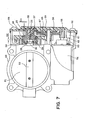
- a throttle valve 51 (rotation body) for controlling an amount of intake air of an internal combustion engine is fixed to a rotation shaft 52.
- the rotation shaft 52 is rotatably supported to a throttle body 53 via a bearing (not-shown).
- a motor 54 (actuator) for actuating the throttle valve 51 is assembled at a lower portion of the throttle body 53. Revolutions of the motor 54 are reduced by a reduction mechanism 65, which is made up of plural gears 55 - 57, and are transmitted to the rotation shaft 52. As a result, the throttle valve 51 is actuated so as to rotate.
- the gear 57 fixed to the rotation shaft 52 of the throttle valve 51 is manufactured by an insert-forming of the rotor core 24 and the permanent magnet 27.
- the gear 57, rotor core 24 and the permanent magnet 27 are integrated, and the integrated structure is fixed to a tip portion of the rotation shaft 52 by using a swaging.
- the gear 57 is pressed to a predetermined rotational direction by a twist coil spring 58, so that the throttle valve is automatically returned to an initial position by a spring force.
- the stator core 25, in which the Hall IC 31 is arranged, and the spacer 32 are insert-formed at the inner side of a resin cover 59, which covers the reduction mechanism 65.
- the cover 59 is fixed to the right end opening of the throttle body 53 by using bolts 66 or the like, so that the stator core 25 and the Hall IC 31 are fixed inner side of the cover 59.
- the angular position detection sensor which is made of the rotor core 24, the permanent magnet 27, the Hall IC 31 and so on, is contained in a space in the cover 59.
- the structure of the angular position detection apparatus is substantially the same as that of the first embodiment.
- a connector housing 61 for being connected to a motor terminal 60 is integrally formed in the cover 59.
- a connector pin 62 in the connector housing 61 is connected to the motor terminal 60.
- the permanent magnet 27 since the permanent magnet 27 is magnetized in parallel, it can improve the linearity of the output characteristic with respect to the angular position of the rotor core 24. Furthermore, air gap dimension G2 between the permanent magnet 27 and the stator core 25 is set larger than an air gap G1 between the cylindrical portion 26 and the stator core 25.
- the angular position detection apparatus is formed in the radial gap type, in which the magnetic flux is gone through along the radial direction, with fixing the permanent magnet 27 to the side surface of the rotor core 24. Therefore, the dimension accuracy of the air gap G1 can be easily controlled with downsizing the outer size of the angular position detection apparatus.
- the permanent magnet 27 is fixed to the rotation shaft 52 of the throttle valve 51, so that the magnetic flux of the permanent magnet 27, which changes in proportion to the rotation of the throttle valve 51, is detected by the Hall IC 31 fixed in the cover 59. Therefore, angular position (throttle opening degree) of the throttle valve 51 can be directly detected, and can improve the detection accuracy of the throttle opening degree.
- the angular position detection apparatus which is provided with the rotor core 24, the permanent magnet 27, the stator core 25, the Hall IC 31 and so on, is contained in the space in the cover 59 of the reduced mechanism. Therefore, it can downsize the entire system compared to the conventional type in the angular position detection apparatus. Since the rotor core 24 and the permanent magnet 27 of the angular position detection apparatus are supported by the rotation shaft 52 of the throttle valve 51, it does not need to support the rotor core 24 and the permanent magnet 27 by the bearing. Therefore, a rotation resistance of the rotation shaft 52 for rotating the rotor core 24 and the permanent magnet 27 can be reduced, and it can reduce a load of the motor 54.
- the gear 57 to be fixed to the rotation shaft 52 of the throttle valve 51 is made of resin.
- the gear 57, the rotor core 24 and the permanent magnet 27 are integrated by the insert-forming.
- the stator core 25 and the Hall IC 31 are integrated by the inserting the cover 59 of the reduction mechanism 65. Therefore, the number of the parts is reduced, it can improve an assembly, and it can reduce a cost.
- the permanent magnet 27 is fixed to the right side surface of the side surface of the rotor core 24; however, it may be fixed to a left side thereof.
- the permanent magnet 27 is magnetized in parallel; however, the permanent magnet 27 may be magnetized so that the line of the magnetic force in the permanent magnet 27 is set to the radial direction (radial-magnetization).
- the angular position detection apparatus is formed as the radial gap type in which the magnetic flux is gone through along the radial direction by confronting the permanent magnet 27 along the axial direction with respect to the stator core 25; however, the angular position detection apparatus may be formed as an axial gap type in which the magnetic flux of the permanent magnet is gone through along the axial direction. Furthermore, the angular position detection apparatus may be formed as a radial gap type in which the magnetic flux of the permanent magnet is gone through along the radial direction, by confronting the permanent magnet with the outer surface of the stator core 25.
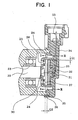
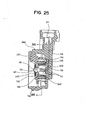
- a rotation shaft 22 of a detection target object such as a throttle valve is inserted and rotatably supported to a main housing 21 of the angular position apparatus via a bearing 23.
- a rotor core 24 having a cylindrical cap shape is fixed to a tip (right side end) of the rotation shaft 22 by being swaged.
- a stator core 25 is concentrically arranged inner side of the rotor core 24.
- Each of the rotor core 24 and the stator core 25 is made of a magnetic material such as iron.
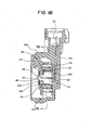
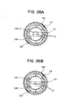
- Only one permanent magnet 27 having a semicircular shape is provided at inner portion of the rotor core 24.
- the rotor core 24 is inserted to a depression portion 126, which is formed along almost semicircle at the inner portion of the rotor core 24, and is fixed by using adhesive, resin mold or the like, so that air gap is uniformly generated along the whole circle of a periphery of the stator core 25.
- the permanent magnet 27 is magnetized so that lines of magnetic force in the permanent magnet are in parallel each other at least under unassembled condition, as shown in FIG 12C. In the case where the permanent magnet 27 is assembled to the rotor core 24, as shown in FIG.
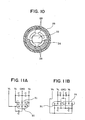
- plural through holes 28 for preventing short-circuit of the magnetic flux are formed to the side left side portion of the rotor core 24 so as to surround the rotation shaft 22 (see FIG 10).
- An outer portion of the rotor core 24 is molded by resin 29.
- a magnetic flux detection gap portion 30, which has a constant width, for forming a parallel magnetic field is formed to a center portion of the stator core 25 so as to go through along a diametral direction (specifically, the stator core 25 is divided into two parts to form the magnetic flux detection gap portion 30 having the constant width, and a width of the magnetic flux detection gap portion 30 is restricted by a resin spacer 32).
- a pair of Hall IC 31 is arranged in the magnetic flux detection gap portion 30.
- Each Hall IC 31 is an IC, in which a Hall element (magnetic detection element) is integrally formed with an amplifying circuit, and outputs a voltage signal in accordance with a magnetic flux density going through the magnetic flux detection gap portion 30 (a magnetic flux density crossing the Hall IC 31).
- a Hall element magnetic detection element
- Each position of each Hall IC 31 is determined by the resin spacer 32.
- a terminal of the Hall IC 31 is connected to a connector pin 33 through inside of the spacer 32 by using welding or the like.
- a connector housing 34 is formed by resin-molding the connector pin 33, the stator core 25, the spacer 32, and so on.
- a depression portion 35 having a ring shape is formed at a left side of the connector housing 34 concentrically with the stator core 25.
- An accuracy of the sameness of the axis between the rotor core 24 and the stator core 25 are secured by inserting a right end portion 36 of the main housing 21 into the ring depression portion 35 with pressure and by fixing them by an adhesives or the like.
- the pair of Hall IC 31 is arranged by stacking toward a direction of the magnetic flux going through the magnetic flux detection gap portion 30.
- the pair of the Hall IC 31 may be arranged along a direction perpendicular to a direction of the magnetic flux going through the magnetic flux detection gap portion 30 (vertical direction).
- a Hall element built in the Hall IC 31 is arranged so that a position of the Hall element is within a range of 0.8 ⁇ D, with respect to a diameter D of the stator core 25. As a result, it can substantially equalize the magnetic flux density crossing the Hall element of the pair of Hall IC 31.
- the Hall IC 31 may include a function for electrically trimming an output gain adjustment regarding the magnetic flux density, an offset adjustment, and a correction of a thermal characteristic, or may include a self diagnosis function for disconnection or short-circuit.
- a magnetic circuit is formed in the following path: an N pole of the permanent magnet 27 ⁇ an upper portion of the stator core 25 ⁇ the magnetic flux detection gap portion 30 ⁇ a lower portion of the stator core 25 ⁇ the rotor core 24 ⁇ an S pole of the permanent magnet 27.
- the magnetic flux going through the magnetic flux detection gap portion 30 of the stator core 25 changes in proportion to the angular position thereof, and an output of the Hall IC 31 changes in proportion to the magnetic flux density.
- a control circuit (not-shown) detects the angular position of the rotor core 24 (angular position of the detection target object) after receiving the output of the Hall IC 31. In this time, the angular position is detected with ascertaining whether there is abnormality or not by comparing two outputs V1 and V2 from the pair of Hall IC 31 each other.
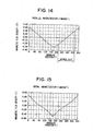
- FIG. 13 shows a comparison in which the magnetization of the permanent magnet 27 is changed to a radial magnetization. According to this comparison, as shown in FIG. 15, the linearity of change in the magnetic flux of the magnetic flux detection portion 30 with respect to the angular position of the rotor core 24 decreases, and the linearity of the output characteristic of the Hall IC 31 decreases, and therefore the detection accuracy of the angular position decreases.
- the permanent magnet 27 since the permanent magnet 27 is magnetized in parallel, as shown in FIG. 14, it can improve the linearity of the change in the magnetic flux density at the magnetic flux detection gap portion 30 with respect to the angular position of the rotor core 24, and can expand the range, in which the magnetic flux density in the magnetic flux detection gap portion 30 linearly changes in proportion to the angular position of the rotor core 24, to or more than approximately 120° (degree). As a result, it can obtain the linear output with respect to the angular position in wider range compared to the related art, and it can improve the detection accuracy of the angular position. Furthermore, the parallel magnetization can make the density of the permanent magnet 27 uniform, so that the strength of the permanent magnet 27 can be increased.
- the permanent magnet 27 is provided at the depression portion 126, which is formed at inner portion of the rotor core 24, the air gap surrounding the peripheral portion of the stator core 25 can be uniformed, and it can secure excellent linearity of the output characteristic with respect to the angular position of the rotor core 24, although only one permanent magnet 27 is provided at one side of the rotor core 24. Moreover, since the permanent magnet 27 is used only one, it can satisfy a demand that reduces of the number of the parts and a cost.
- the pair of Hall IC 31 is arranged to or perpendicular to the direction of the magnetic flux in the magnetic flux detection gap portion 30, and is arranged so that the position of the Hall IC 31 is within 0.8 ⁇ D with respect to a diameter D of the stator core 25. Therefore, magnetic flux density crossing the Hall element of each Hall IC 31 can be substantially uniform; and the angular position can be detected with ascertaining whether there is no abnormality by comparing the outputs from the plural magnetic detection elements. Thus, reliability of the angular position detection apparatus can be improved.
- the angular position detection apparatus is formed in the radial gap type in which the stator core 25 and the permanent magnet 27 are confronted with each other along the radial direction. Therefore, it can easily secure the accuracy of the sameness of the axis between the rotor core 24 (permanent magnet 27) and the stator core 25 and can secure the accuracy of the dimension of the air gap along the radial direction therebetween with a simple method, in which the right end portion 36 of the main housing 21 is fixed to the ring depression portion 35 of the connector housing 34. As a result, it facilitates to make the air gap G1 uniformly and small, and it can easily improve the linearity of the output characteristic of the Hall IC 31 with respect to the angular position.
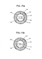
- FIGS. 16, 17A and 17B a fifth embodiment of the present invention will be explained with reference to FIGS. 16, 17A and 17B.
- portions, which are substantially the same portion as those of the fourth embodiment, are put the same symbols to omit explanations.
- a rotation lever 137 for connecting with the detection target object is formed by molding the rotor core 24 and the permanent magnet 27 using resin.
- a molded resin portion, which is an inner side of the rotor core 24 and the permanent magnet 27, of the rotation lever 137 is inserted and rotatably supported to an outer side of a stator core 139.
- the molded resin portion, which is an inner side of the rotor core 24 and the permanent magnet 27, acts as a bearing (slidably movable portion) with respect to the stator core 139. Therefore, the magnetic gap between the rotor core 24 and the periphery of the stator core 139 with respect to the permanent magnet 27 is secured by a thickness of the molded resin.
- the rotation lever 137 is pressed to a predetermined rotational direction by a twist coil spring 141, and is automatically returned to an initial position by a spring force.
- a through hole 38 is formed in a center portion of the rotation lever 137.
- a small-diameter portion 40 provided at a left end portion of the stator core 139 is inserted to the through hole 38.
- a stopper plate 143 which is fixed to a tip portion of the small-diameter portion 40, prevents the rotation lever 137 from being removed from the stator core 139.
- a ring washer 142 for restricting a movement of the rotation lever toward a thrust direction is sandwiched between the stopper plate 143 and the rotation lever 137.
- the magnetic flux detection gap portion 30, which passes through toward a diametral direction, is formed to a center portion of the stator core 139.
- a pair of Hall IC 31 is arranged in the magnetic flux detection gap portion 30, by stacking toward a direction of the magnetic flux going through the magnetic flux detection gap portion 30.
- the pair of the Hall IC 31 may be arranged along a direction perpendicular to a direction of the magnetic flux going through the magnetic flux detection gap portion 30.
- a cylindrical cover portion 144 is integrally formed with the connector housing 34 so as to surround peripheries of the rotation lever 137 or the rotor core 24.
- the permanent magnet 27 is parallel magnetized as the same way as the fourth embodiment. As a result, it can expand the range, in which the magnetic flux density in the magnetic flux detection gap portion 30 linearly changes in proportion to the angular position of the rotor core 24, compared to the radial magnetization as the related art. Moreover, it can obtain the linear output with respect to the angular position in wider range compared to the related art, and it can improve the detection accuracy of the angular position.
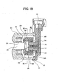
- FIGS. 18 through 24 a sixth embodiment of the present invention will be explained with reference to FIGS. 18 through 24.
- the sixth embodiment has many common portions with the fourth embodiment, portions, which are substantially the same portion as those of the fourth embodiment, are put the same symbols to omit explanations.
- the fourth embodiment only one permanent magnet 27 is provided at one side of the rotor core 24.
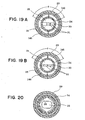
- two permanent magnets 145 and 146 are provided at both sides of the rotor core 24 so as to confront with each other.
- the upper permanent magnet 145 is magnetized so that an outer side becomes S pole and an inner side becomes N pole; and the lower permanent magnet 146 is magnetized so that an outer side becomes N pole and an inner side becomes S pole.
- these permanent magnets 145 and 36 are mounted on the rotor core 24, when the stator core 25 is not provided at the inner side of the rotor core 24 as shown in FIG.
- lines of the magnetic force in the upper permanent magnet 145 are inclined to outer side, and lines of the magnetic force in the lower permanent magnet 146 are inclined to inner side. Furthermore, in a case where the stator core 25 is provided at the inner side of the rotor core 24, since the magnetic flux of the upper permanent magnet 145 goes through the lower permanent magnet 146 via the stator core 25 as shown in FIG. 21A, an inclination of the lines of the magnetic force in the permanent magnets 145 and 146 decrease to substantially parallel condition.
- the pair of Hall IC 31 is arranged in the magnet flux detection gap portion 30 so as to be stacked in the direction of the magnetic flux (see FIG. 29A), or is arranged along the direction perpendicular to the direction of the magnet flux detection gap portion 30 so as to be stacked in the direction of the magnetic flux (see FIG. 19B).
- a pair of permanent magnets 13 is radially magnetized.
- a range, in which the magnetic flux in the magnetic flux detection gap portion 14 linearly changes in proportion to the angular position of the rotor core 11, is at most approximately 80° (degree). Therefore, when the angular position exceeds 80° (degree), it is impossible to obtain linear output with respect to the angular position can, and a detection accuracy of the angular position decreases.
- the permanent magnets 145 and 146 are parallel magnetized, as shown in FIG. 23A, the range, in which the magnetic flux in the magnetic flux detection gap portion 30 linearly changes in proportion to the angular position of the rotor core 11, can be expanded to approximately 100 (degree) (when an angle of circumference ⁇ of each permanent magnet 145, 146 shown in FIGS. 19A and 19B is approximately 100° (degree), it can obtain the linear output with respect to the angular position in wider range compared to the related art, and it can improve the detection accuracy of the angular position.
- each permanent magnet 145, 146 When the angle of circumference ⁇ of each permanent magnet 145, 146 is set to approximately 180° (degree), the range, in which the magnetic flux in the magnetic flux detection gap portion 14 linearly changes in proportion to the angular position, can be expanded to approximately 120° (degree)as shown in FIG. 23B, and can obtain the linear output with respect to the angular position in further wider range.
- the range, in which the magnetic flux in the magnetic flux detection gap portion 14 linearly changes in proportion to the angular position can be expanded to more than 100° (degree)when the angle of circumference ⁇ of each permanent magnet 145, 146 is set to more than 90° (degree).
- the magnetic flux density going through the magnetic flux detection gap portion 30 in the stator core 25 can be increased, outputs from the Hall element can be increased, and detection accuracy of the angular position can be improved.
- the magnetic flux to be detected increases, it can reduce an amplification factor of the output signal from the magnetic detection element, and can simplifies a structure of a signal amplifying circuit. As a result, it can reduce a cost of the Hall IC 31.
- the seventh embodiment can also obtain the same effects as that of the sixth embodiment in which two permanent magnets 145 and 146, each of which is parallel magnetized, is arranged.
- the number of the Hall IC 31 to be arranged at the magnetic flux detection gap portion 30 is 2; however, it may be only one. Furthermore, when the magnetic flux detection gap portion 30 has enough space, three or more Hall IC 31 may be arranged in the magnetic flux direction or the perpendicular thereof. Moreover, as the magnetic detection element for detecting the magnetic flux density of the magnetic flux detection gap portion 30, a magnetic resistance element or the like may be used instead of the Hall IC (Hall element).
- the present invention is not limited to the angular position detection apparatus for throttle valve; but is applicable to angular position detection apparatuses for several types of rotators.
Landscapes
- Physics & Mathematics (AREA)
- General Physics & Mathematics (AREA)
- Transmission And Conversion Of Sensor Element Output (AREA)
Applications Claiming Priority (7)
| Application Number | Priority Date | Filing Date | Title |
|---|---|---|---|
| JP17165199 | 1999-06-17 | ||
| JP17165099 | 1999-06-17 | ||
| JP17165099 | 1999-06-17 | ||
| JP17165199A JP3496581B2 (ja) | 1999-06-17 | 1999-06-17 | 回転角検出装置 |
| JP24430699 | 1999-08-31 | ||
| JP24430699A JP3539299B2 (ja) | 1999-06-17 | 1999-08-31 | 回転角検出装置 |
| EP00112683A EP1061341A3 (de) | 1999-06-17 | 2000-06-15 | Winkelstellungsdetektor |
Related Parent Applications (2)
| Application Number | Title | Priority Date | Filing Date |
|---|---|---|---|
| EP00112683.8 Division | 2000-06-15 | ||
| EP00112683A Division EP1061341A3 (de) | 1999-06-17 | 2000-06-15 | Winkelstellungsdetektor |
Publications (2)
| Publication Number | Publication Date |
|---|---|
| EP1467184A2 true EP1467184A2 (de) | 2004-10-13 |
| EP1467184A3 EP1467184A3 (de) | 2012-02-15 |
Family
ID=27323515
Family Applications (2)
| Application Number | Title | Priority Date | Filing Date |
|---|---|---|---|
| EP03012601A Withdrawn EP1467184A3 (de) | 1999-06-17 | 2000-06-15 | Winkelstellungsdetektor |
| EP00112683A Withdrawn EP1061341A3 (de) | 1999-06-17 | 2000-06-15 | Winkelstellungsdetektor |
Family Applications After (1)
| Application Number | Title | Priority Date | Filing Date |
|---|---|---|---|
| EP00112683A Withdrawn EP1061341A3 (de) | 1999-06-17 | 2000-06-15 | Winkelstellungsdetektor |
Country Status (2)
| Country | Link |
|---|---|
| US (1) | US6483296B1 (de) |
| EP (2) | EP1467184A3 (de) |
Cited By (2)
| Publication number | Priority date | Publication date | Assignee | Title |
|---|---|---|---|---|
| WO2007122055A1 (de) * | 2006-04-21 | 2007-11-01 | Continental Automotive Gmbh | Magnetischer drehwinkelgeber |
| WO2011139469A1 (en) * | 2010-05-05 | 2011-11-10 | Continental Automotive Systems, Inc. | Rotary arc position sensor with linear output |
Families Citing this family (37)
| Publication number | Priority date | Publication date | Assignee | Title |
|---|---|---|---|---|
| JP3866899B2 (ja) * | 2000-04-06 | 2007-01-10 | 株式会社日立製作所 | 内燃機関のスロットル弁制御装置及び自動車 |
| JP3875562B2 (ja) * | 2001-06-25 | 2007-01-31 | 矢崎総業株式会社 | コンビネーションスイッチ |
| JP3775257B2 (ja) | 2001-07-30 | 2006-05-17 | アイシン精機株式会社 | 角度センサ |
| US6657346B2 (en) * | 2001-08-24 | 2003-12-02 | Huang Chuan Pan | Device for detecting the rotating speed of a fan motor |
| DE60309361T2 (de) * | 2002-03-06 | 2007-02-08 | Borgwarner Inc., Auburn Hills | Elektronische Drosselklappensteuerung mit berührlosem Positionsgeber |
| US7191754B2 (en) * | 2002-03-06 | 2007-03-20 | Borgwarner Inc. | Position sensor apparatus and method |
| JP3913657B2 (ja) * | 2002-10-02 | 2007-05-09 | 株式会社日本自動車部品総合研究所 | トルクセンサ |
| JP2004251831A (ja) * | 2003-02-21 | 2004-09-09 | Aisan Ind Co Ltd | 回転角検出装置 |
| JP4098149B2 (ja) * | 2003-05-08 | 2008-06-11 | 愛三工業株式会社 | スロットル制御装置 |
| JP3983722B2 (ja) * | 2003-08-04 | 2007-09-26 | 三菱電機株式会社 | エンジン用吸気制御装置 |
| US20050068024A1 (en) * | 2003-09-29 | 2005-03-31 | Byram Robert James | Rotary position sensor |
| JP4045230B2 (ja) * | 2003-11-04 | 2008-02-13 | 三菱電機株式会社 | 非接触式回転角度検出装置 |
| JP4224382B2 (ja) * | 2003-11-18 | 2009-02-12 | 株式会社日立製作所 | 回転位置センサ及び内燃機関の電子制御式スロットル装置 |
| DE10360234B3 (de) * | 2003-12-20 | 2005-04-14 | Pierburg Gmbh | Sensoranordnung für eine Klappenvorrichtung in einem Luftansaugkanalsystem |
| KR100720176B1 (ko) * | 2005-06-08 | 2007-05-18 | 주식회사 캐프스 | 비접촉식 센서를 이용한 연료잔량 감지용 센더 유니트 |
| DE102005040647A1 (de) * | 2005-08-27 | 2007-03-08 | Valeo Systèmes d`Essuyage | Elektromotorischer Hilfsantrieb für Fahrzeuge |
| DE102005059538B4 (de) | 2005-12-13 | 2018-08-23 | Asm Automation Sensorik Messtechnik Gmbh | Scharnier-Sensor |
| DE102007001118A1 (de) * | 2007-01-04 | 2008-07-10 | Robert Bosch Gmbh | Sensorvorrichtung zur Messungen von Drehbewegungen eines Radlagers |
| DE102007016133A1 (de) * | 2007-03-29 | 2008-10-02 | Robert Bosch Gmbh | Messeinrichtung zur berührungslosen Erfassung eines Drehwinkels mit in einer Ausnehmung des Magneten angeordnetem magnetempfindlichen Element |
| US8857464B2 (en) * | 2008-01-30 | 2014-10-14 | Flowserve Management Company | Valve actuators having magnetic angle sensors |
| JP5085379B2 (ja) * | 2008-03-13 | 2012-11-28 | 株式会社デンソー | 弁装置 |
| JP5417721B2 (ja) * | 2008-03-13 | 2014-02-19 | 日本電産株式会社 | モータ |
| US20100176803A1 (en) * | 2009-01-12 | 2010-07-15 | Infineon Technologies Ag | Angle sensor with flux guides, rotatable magnet and magnetic sensor |
| DE112009005068T5 (de) * | 2009-07-14 | 2013-10-10 | Mitsubishi Electric Corp. | Fahrzeugzustandserfassungseinrichtung und Verfahren zurHerstellung derselben |
| US8966289B2 (en) * | 2010-12-17 | 2015-02-24 | Nxp B.V. | Pairing of angle sensor and electronic control unit |
| JP5517083B2 (ja) * | 2011-04-22 | 2014-06-11 | 株式会社デンソー | 回転角センサ |
| JP5825520B2 (ja) | 2011-12-28 | 2015-12-02 | 日本精機株式会社 | 液面検出装置 |
| JP6110759B2 (ja) * | 2013-08-27 | 2017-04-05 | アルプス電気株式会社 | 移動検知装置ならびにアクチュエータ |
| JP6239342B2 (ja) * | 2013-10-24 | 2017-11-29 | 日立金属株式会社 | 車両用検出装置 |
| US9267781B2 (en) * | 2013-11-19 | 2016-02-23 | Infineon Technologies Ag | On-axis magnetic field angle sensors, systems and methods |
| JP3215077U (ja) * | 2015-01-23 | 2018-03-01 | インフィネオン テクノロジーズ アーゲーInfineon Technologies Ag | シャフト外磁気角度感知システム |
| DE102015101248A1 (de) | 2015-01-28 | 2016-07-28 | Fraba B.V. | Magnet-basiertes Drehwinkelmesssystem |
| DE102015101246A1 (de) * | 2015-01-28 | 2016-07-28 | Fraba B.V. | Magnet-basiertes Drehwinkelmesssystem |
| JP6233455B1 (ja) * | 2016-06-09 | 2017-11-22 | 愛知製鋼株式会社 | 回転機 |
| DE102016223681A1 (de) * | 2016-11-29 | 2018-05-30 | Schaeffler Technologies AG & Co. KG | Klappenanordnung für ein Fahrzeug |
| JP7366848B2 (ja) * | 2020-07-03 | 2023-10-23 | Tdk株式会社 | 角度検出装置、角度検出装置システム、パークロックシステム、およびペダルシステム |
| US11722036B2 (en) | 2021-06-14 | 2023-08-08 | Commercial Vehicle Group, Inc. | Wiper motors and methods of manufacture and use thereof |
Citations (2)
| Publication number | Priority date | Publication date | Assignee | Title |
|---|---|---|---|---|
| DE29606042U1 (de) * | 1996-04-01 | 1996-06-20 | Ruf Kg Wilhelm | Drehstellungsmeßfühler für die Drehstellung einer Welle |
| WO1998043047A1 (de) * | 1997-03-21 | 1998-10-01 | Mannesmann Vdo Ag | Bedienvorrichtung |
Family Cites Families (11)
| Publication number | Priority date | Publication date | Assignee | Title |
|---|---|---|---|---|
| JPH0466813A (ja) * | 1990-07-06 | 1992-03-03 | Mitsubishi Electric Corp | 角度検出センサ |
| FR2670286B1 (fr) | 1990-12-05 | 1993-03-26 | Moving Magnet Tech | Capteur magnetique de position et de vitesse a sonde de hall. |
| US5789917A (en) | 1990-12-05 | 1998-08-04 | Moving Magnet Technologie Sa | Magnetic position sensor with hall probe formed in an air gap of a stator |
| JP3206204B2 (ja) * | 1992-05-22 | 2001-09-10 | 株式会社デンソー | スロットルポジションセンサ |
| US5332965A (en) | 1992-06-22 | 1994-07-26 | Durakool Incorporated | Contactless linear angular position sensor having an adjustable flux concentrator for sensitivity adjustment and temperature compensation |
| EP0755480B1 (de) | 1995-02-10 | 2000-07-12 | Koninklijke Philips Electronics N.V. | Vorrichtung zur betätigung eines steuerelements |
| DE19630764A1 (de) | 1995-09-29 | 1997-04-03 | Bosch Gmbh Robert | Meßvorrichtung zur berührungslosen Erfassung einer Relativbewegung |
| DE19634282A1 (de) | 1996-08-24 | 1998-02-26 | Bosch Gmbh Robert | Meßvorrichtung zur berührungslosen Erfassung eines Drehwinkels |
| DE19634281C2 (de) | 1996-08-24 | 2000-01-27 | Bosch Gmbh Robert | Meßvorrichtung zur berührungslosen Erfassung eines Drehwinkels bzw. einer linearen Bewegung |
| EP0882210B1 (de) * | 1996-12-04 | 2001-08-08 | AB Elektronik GmbH | Drehwinkelsensor |
| US6201388B1 (en) * | 1997-11-10 | 2001-03-13 | Invensys Building Systems, Inc. | Device for determining the angular position of a rotating member utilizing a magnetic hall effect transducer |
-
2000
- 2000-06-09 US US09/589,772 patent/US6483296B1/en not_active Expired - Fee Related
- 2000-06-15 EP EP03012601A patent/EP1467184A3/de not_active Withdrawn
- 2000-06-15 EP EP00112683A patent/EP1061341A3/de not_active Withdrawn
Patent Citations (2)
| Publication number | Priority date | Publication date | Assignee | Title |
|---|---|---|---|---|
| DE29606042U1 (de) * | 1996-04-01 | 1996-06-20 | Ruf Kg Wilhelm | Drehstellungsmeßfühler für die Drehstellung einer Welle |
| WO1998043047A1 (de) * | 1997-03-21 | 1998-10-01 | Mannesmann Vdo Ag | Bedienvorrichtung |
Cited By (6)
| Publication number | Priority date | Publication date | Assignee | Title |
|---|---|---|---|---|
| WO2007122055A1 (de) * | 2006-04-21 | 2007-11-01 | Continental Automotive Gmbh | Magnetischer drehwinkelgeber |
| US8111064B2 (en) | 2006-04-21 | 2012-02-07 | Continental Automotive Gmbh | Magnetic rotational angle transducer |
| WO2011139469A1 (en) * | 2010-05-05 | 2011-11-10 | Continental Automotive Systems, Inc. | Rotary arc position sensor with linear output |
| CN102869954A (zh) * | 2010-05-05 | 2013-01-09 | 大陆汽车系统公司 | 具有线性输出的旋转弧位置传感器 |
| CN102869954B (zh) * | 2010-05-05 | 2016-01-06 | 大陆汽车系统公司 | 具有线性输出的旋转弧位置传感器 |
| US9841296B2 (en) | 2010-05-05 | 2017-12-12 | Continental Automotive Systems, Inc. | Rotary arc position sensor with linear output |
Also Published As
| Publication number | Publication date |
|---|---|
| EP1467184A3 (de) | 2012-02-15 |
| US6483296B1 (en) | 2002-11-19 |
| EP1061341A2 (de) | 2000-12-20 |
| EP1061341A3 (de) | 2003-05-07 |
Similar Documents
| Publication | Publication Date | Title |
|---|---|---|
| EP1467184A2 (de) | Winkelstellungsdetektor | |
| EP1111343B1 (de) | Verfahren und Vorrichtung zur berührungslosen Positionsmessung | |
| EP1065473B1 (de) | Winkelpositionsmessvorrichtung | |
| US7868504B2 (en) | Resolver | |
| US6559637B2 (en) | Non-contact rotational position sensor and throttle valve assembly including non-contact rotational position sensor | |
| US6414482B1 (en) | Non-contact type rotational angle sensor and sensor core used in the sensor | |
| US5861745A (en) | Measuring device for contactless determination of relative angular position with an improved linear range | |
| JP5064315B2 (ja) | 回転角度センサ | |
| JP4433886B2 (ja) | 回転角度検出装置 | |
| US8525458B2 (en) | Brushless motor position detection device | |
| CN101243598B (zh) | 电动机 | |
| US7019516B2 (en) | Magnetic sensor unit less responsive to leaking magnetic flux | |
| US20050223820A1 (en) | Torque detecting apparatus and manufacturing method thereof | |
| JP5944703B2 (ja) | 回転角度検出装置 | |
| US20040085062A1 (en) | Noncontact rotary position sensor and electric control throttle valve apparatus having noncontact rotary position | |
| JP2005147926A (ja) | 回転位置センサ及び内燃機関の電子制御式スロットル装置 | |
| JP4038664B2 (ja) | ステッピングモータ | |
| US6448762B1 (en) | Rotation-angle-detection device having magnetic sensor fixed to cover with detection direction transverse to cover longitudinal direction | |
| CN102032865A (zh) | 旋转角传感装置 | |
| JP3539299B2 (ja) | 回転角検出装置 | |
| JP3496581B2 (ja) | 回転角検出装置 | |
| US20100180696A1 (en) | Systems involving compact torque sensing | |
| JPWO2005040730A1 (ja) | 回転角検出装置 | |
| US10677171B2 (en) | Angle detection mechanism and angle detection system | |
| JP3438692B2 (ja) | 回転角検出装置 |
Legal Events
| Date | Code | Title | Description |
|---|---|---|---|
| PUAI | Public reference made under article 153(3) epc to a published international application that has entered the european phase |
Free format text: ORIGINAL CODE: 0009012 |
|
| 17P | Request for examination filed |
Effective date: 20030603 |
|
| AC | Divisional application: reference to earlier application |
Ref document number: 1061341 Country of ref document: EP Kind code of ref document: P |
|
| AK | Designated contracting states |
Kind code of ref document: A2 Designated state(s): DE FR GB |
|
| PUAL | Search report despatched |
Free format text: ORIGINAL CODE: 0009013 |
|
| AK | Designated contracting states |
Kind code of ref document: A3 Designated state(s): DE FR GB |
|
| RIC1 | Information provided on ipc code assigned before grant |
Ipc: G01D 5/14 20060101AFI20120112BHEP |
|
| AKX | Designation fees paid |
Designated state(s): DE FR GB |
|
| 17Q | First examination report despatched |
Effective date: 20130910 |
|
| STAA | Information on the status of an ep patent application or granted ep patent |
Free format text: STATUS: THE APPLICATION IS DEEMED TO BE WITHDRAWN |
|
| 18D | Application deemed to be withdrawn |
Effective date: 20140121 |