EP1466732B1 - Verfahren zum Trocknen einer Druckfarbe auf einem Bedruckstoff und Druckwerk, geeignet zur Durchführung des Verfahrens - Google Patents
Verfahren zum Trocknen einer Druckfarbe auf einem Bedruckstoff und Druckwerk, geeignet zur Durchführung des Verfahrens Download PDFInfo
- Publication number
- EP1466732B1 EP1466732B1 EP04005820A EP04005820A EP1466732B1 EP 1466732 B1 EP1466732 B1 EP 1466732B1 EP 04005820 A EP04005820 A EP 04005820A EP 04005820 A EP04005820 A EP 04005820A EP 1466732 B1 EP1466732 B1 EP 1466732B1
- Authority
- EP
- European Patent Office
- Prior art keywords
- printing
- substrate
- light
- wavelength
- laser light
- Prior art date
- Legal status (The legal status is an assumption and is not a legal conclusion. Google has not performed a legal analysis and makes no representation as to the accuracy of the status listed.)
- Expired - Lifetime
Links
- 238000007639 printing Methods 0.000 title claims abstract description 261
- 238000001035 drying Methods 0.000 title claims abstract description 32
- 239000000758 substrate Substances 0.000 title claims description 56
- 238000000034 method Methods 0.000 title claims description 30
- 239000000976 ink Substances 0.000 claims abstract description 74
- 238000010521 absorption reaction Methods 0.000 claims description 43
- 239000000049 pigment Substances 0.000 claims description 41
- 239000000463 material Substances 0.000 claims description 27
- XLYOFNOQVPJJNP-UHFFFAOYSA-N water Substances O XLYOFNOQVPJJNP-UHFFFAOYSA-N 0.000 claims description 9
- 238000005286 illumination Methods 0.000 claims description 5
- 239000004065 semiconductor Substances 0.000 claims description 4
- 239000003086 colorant Substances 0.000 abstract description 3
- 239000004033 plastic Substances 0.000 abstract 2
- 229920003023 plastic Polymers 0.000 abstract 2
- 239000002904 solvent Substances 0.000 description 14
- 230000005855 radiation Effects 0.000 description 11
- 238000011161 development Methods 0.000 description 7
- 230000018109 developmental process Effects 0.000 description 7
- 239000000123 paper Substances 0.000 description 6
- 238000012545 processing Methods 0.000 description 6
- 239000000126 substance Substances 0.000 description 5
- 239000006096 absorbing agent Substances 0.000 description 4
- 230000000694 effects Effects 0.000 description 4
- 238000010438 heat treatment Methods 0.000 description 4
- 238000007645 offset printing Methods 0.000 description 4
- 230000003595 spectral effect Effects 0.000 description 4
- 239000011230 binding agent Substances 0.000 description 3
- 238000003384 imaging method Methods 0.000 description 3
- 239000002245 particle Substances 0.000 description 3
- 238000006116 polymerization reaction Methods 0.000 description 3
- 239000011347 resin Substances 0.000 description 3
- 229920005989 resin Polymers 0.000 description 3
- 238000011144 upstream manufacturing Methods 0.000 description 3
- 239000005371 ZBLAN Substances 0.000 description 2
- 230000001419 dependent effect Effects 0.000 description 2
- 238000001704 evaporation Methods 0.000 description 2
- 230000008020 evaporation Effects 0.000 description 2
- 239000011521 glass Substances 0.000 description 2
- 238000000926 separation method Methods 0.000 description 2
- 230000001960 triggered effect Effects 0.000 description 2
- FOXXZZGDIAQPQI-XKNYDFJKSA-N Asp-Pro-Ser-Ser Chemical compound OC(=O)C[C@H](N)C(=O)N1CCC[C@H]1C(=O)N[C@@H](CO)C(=O)N[C@@H](CO)C(O)=O FOXXZZGDIAQPQI-XKNYDFJKSA-N 0.000 description 1
- 229910052691 Erbium Inorganic materials 0.000 description 1
- RTAQQCXQSZGOHL-UHFFFAOYSA-N Titanium Chemical compound [Ti] RTAQQCXQSZGOHL-UHFFFAOYSA-N 0.000 description 1
- 238000000862 absorption spectrum Methods 0.000 description 1
- 238000013459 approach Methods 0.000 description 1
- XKRFYHLGVUSROY-UHFFFAOYSA-N argon Substances [Ar] XKRFYHLGVUSROY-UHFFFAOYSA-N 0.000 description 1
- 229910052786 argon Inorganic materials 0.000 description 1
- -1 argon ions Chemical class 0.000 description 1
- QVGXLLKOCUKJST-UHFFFAOYSA-N atomic oxygen Chemical compound [O] QVGXLLKOCUKJST-UHFFFAOYSA-N 0.000 description 1
- 238000006243 chemical reaction Methods 0.000 description 1
- 239000011248 coating agent Substances 0.000 description 1
- 238000000576 coating method Methods 0.000 description 1
- 239000000470 constituent Substances 0.000 description 1
- XCJYREBRNVKWGJ-UHFFFAOYSA-N copper(II) phthalocyanine Chemical compound [Cu+2].C12=CC=CC=C2C(N=C2[N-]C(C3=CC=CC=C32)=N2)=NC1=NC([C]1C=CC=CC1=1)=NC=1N=C1[C]3C=CC=CC3=C2[N-]1 XCJYREBRNVKWGJ-UHFFFAOYSA-N 0.000 description 1
- 230000008878 coupling Effects 0.000 description 1
- 238000010168 coupling process Methods 0.000 description 1
- 238000005859 coupling reaction Methods 0.000 description 1
- 238000000354 decomposition reaction Methods 0.000 description 1
- 238000009792 diffusion process Methods 0.000 description 1
- 230000005670 electromagnetic radiation Effects 0.000 description 1
- 238000000295 emission spectrum Methods 0.000 description 1
- 238000005516 engineering process Methods 0.000 description 1
- UYAHIZSMUZPPFV-UHFFFAOYSA-N erbium Chemical compound [Er] UYAHIZSMUZPPFV-UHFFFAOYSA-N 0.000 description 1
- 239000005383 fluoride glass Substances 0.000 description 1
- 238000009472 formulation Methods 0.000 description 1
- 239000007789 gas Substances 0.000 description 1
- 238000009434 installation Methods 0.000 description 1
- 230000001678 irradiating effect Effects 0.000 description 1
- 239000000203 mixture Substances 0.000 description 1
- 239000003921 oil Substances 0.000 description 1
- 230000003287 optical effect Effects 0.000 description 1
- 239000013307 optical fiber Substances 0.000 description 1
- 238000013021 overheating Methods 0.000 description 1
- 230000001590 oxidative effect Effects 0.000 description 1
- 239000001301 oxygen Substances 0.000 description 1
- 229910052760 oxygen Inorganic materials 0.000 description 1
- 239000003973 paint Substances 0.000 description 1
- 230000001846 repelling effect Effects 0.000 description 1
- 229910052594 sapphire Inorganic materials 0.000 description 1
- 239000010980 sapphire Substances 0.000 description 1
- 238000007650 screen-printing Methods 0.000 description 1
- 239000007787 solid Substances 0.000 description 1
- 230000002123 temporal effect Effects 0.000 description 1
- 229910052719 titanium Inorganic materials 0.000 description 1
- 239000010936 titanium Substances 0.000 description 1
- 239000002918 waste heat Substances 0.000 description 1
Images
Classifications
-
- B—PERFORMING OPERATIONS; TRANSPORTING
- B41—PRINTING; LINING MACHINES; TYPEWRITERS; STAMPS
- B41F—PRINTING MACHINES OR PRESSES
- B41F23/00—Devices for treating the surfaces of sheets, webs, or other articles in connection with printing
- B41F23/04—Devices for treating the surfaces of sheets, webs, or other articles in connection with printing by heat drying, by cooling, by applying powders
- B41F23/044—Drying sheets, e.g. between two printing stations
-
- B—PERFORMING OPERATIONS; TRANSPORTING
- B41—PRINTING; LINING MACHINES; TYPEWRITERS; STAMPS
- B41M—PRINTING, DUPLICATING, MARKING, OR COPYING PROCESSES; COLOUR PRINTING
- B41M7/00—After-treatment of prints, e.g. heating, irradiating, setting of the ink, protection of the printed stock
- B41M7/0081—After-treatment of prints, e.g. heating, irradiating, setting of the ink, protection of the printed stock using electromagnetic radiation or waves, e.g. ultraviolet radiation, electron beams
Definitions
- the invention relates to a method for drying a printing ink on a substrate in a printing machine, wherein the substrate is printed at a position of a path along which the substrate is moved by the printing press, with at least one ink with at least one color pigment and wherein temporally downstream of the Substrate is illuminated at least one further position of the path with light from a laser light source. Furthermore, the invention relates to a printing unit with a laser light source for carrying out the method.
- planographic printing machines such as lithographic printing machines, rotary printing machines, offset printing machines, flexo printing machines and the like, which arcuate or web-shaped substrates, especially paper, cardboard, cardboard and the like, which are known to initiate or assist adhesion of the ink to the printing material by supplying radiant energy, in particular in the form of light, to the printing ink present on the printing substrate.
- UV inks cure by polymerization, which is triggered by photo-initiation by means of light in the ultraviolet.
- solvent-based printing inks which can undergo both a physical and a chemical drying process, are widely used.
- the physical drying comprises the evaporation of solvents and the diffusion into the printing material (knocking off), while chemical drying or oxidative drying due to polymerization of the oils, resins, binders or the like contained in the paint formulations is possibly understood to mean the presence of atmospheric oxygen.
- the drying processes are generally dependent on each other, since the separation of the solvents causes a separation within the binder system between solvents and resins, as a result of which the resin molecules can approach and possibly polymerize more easily.
- a device for drying printed products which comprises a radiation energy source in the form of a laser.
- the radiant energy is conducted to the surface of the substrates, which move on a web by means of a transport device through the printing press, at a position between individual printing units or after the last printing unit before or in the boom.
- the radiation source may be a laser in the ultraviolet for UV inks or a laser light source for heating solvent-based inks.
- the source of radiation energy is located outside the printing press to avoid undesirable heating of parts of the printing press due to unavoidable or shieldable waste heat.
- an additional system component for the printing press must be provided separately.
- an electrophotographic printing machine or copying machine has a plurality of toner fixing devices wherein each of the fixing means emits a wavelength range of electromagnetic radiation which corresponds to a maximum absorption wavelength of the toner species associated with this fixing means but has no or only slight absorption at absorption wavelengths of the other types of toner.
- solvent-based printing ink refers in particular to colors whose solvent constituents may be of aqueous or organic nature, which build up on binder systems which can be polymerized oxidatively, ionically or radically.
- An energy input for drying of solvent-based printing inks should support or promote the effect of evaporation of the solvent and / or the effect of repelling the substrate and / or the effect of the polymerization, while undesirable side effects, such as in particular excessive heating of the solvent-containing printing ink, which can lead to decomposition of components or overheating of the solvent can be avoided.
- the energy input should not only be introduced to melt particles, as in the case of toner fixation.
- an ink to be printed in a printing unit is incorporated with an infrared absorber - a substance which absorbs in the near infrared spectral range.
- an infrared absorber a substance which absorbs in the near infrared spectral range.
- a narrow-band radiant energy source arranged downstream of the printing gap, preferably a laser light source
- the printing ink is illuminated on the printing substrate.
- the application of light of a wavelength which is substantially resonant to an absorption wavelength of the infrared absorber causes, enables or promotes an energy input into the ink such that the ink is dried.
- the wavelength of the radiation energy source and the absorption wavelength of the infrared absorber are chosen such that at the same time the wavelength used is non-resonant to water, so that the energy input is reduced or avoided in the substrate.
- the object of the present invention is to provide a method for drying printing ink in a printing machine by means of light from a narrow-band radiation energy source, in which the admixture of an infrared absorber substance to be printed Printing inks can be dispensed with. Furthermore, a printing unit, suitable for carrying out this method should be created.
- the printing material is moved along a path through the printing press.
- the printing substrate is printed with at least one printing ink, in particular an offset printing ink having at least one color pigment.
- the printing material is illuminated at least at a further position of the path with light from a narrow-band radiation energy source, a laser light source, the light having a wavelength, in particular only one wavelength, between 350 nm and 700 nm, which is substantially resonant to an absorption wavelength of the at least one color pigment is the at least one printing ink.
- Narrow-band means that the light source emits only wavelengths ⁇ 20.0 nm, preferably ⁇ 10.0 nm, in particular ⁇ 2 nm, or even only a spectroscopically narrow line around a central wavelength.
- a laser light source emitting light of a wavelength between 350 nm and 700 nm is used or used, the light being substantially resonant to an absorption wavelength of the at least one color pigment of the at least one printing ink. In this way an efficient and fast drying is possible. On Infrarotabsorberstoffe in the color can be omitted.
- the inventive method is based on the finding that the very good absorption capacity of color pigments, in particular common standard pigments, which are used in printing inks, especially offset inks, for coupling an energy input in the form of light in the ink layer of a freshly printed with a printing substrate can be exploited.
- the absorption of the radiation energy is supported, enabled, effected or at least accelerated by the at least one color pigment in the ink.
- An influence on the drying process is achieved by the resulting heat. Possibly. be through the generated heat triggered chemical reactions.
- special laser light sources which emit light at this particular wavelength can be used.
- the wavelength of the light used is between 450 nm and 750 nm.
- Color pigments of conventional offset printing inks (standard: cyan C, magenta M, yellow Y and black K) absorb very well between 350 nm and 700 nm 400 nm to 500 nm typically the printing inks C, M, Y, K, at 400 nm to 600 nm C, M, K and at 400 nm to 750 nm C and K.
- the absorption maxima are as follows: C (Clariant standard pigment Blue 15: 3) 650 ⁇ 100 nm at low absorption even below 550 nm to 400 nm, M (Clariant Standard Pigment Red 57: 1) 500 ⁇ 100 nm, and Y (Clariant Standard Pigment Yellow 13) 400 ⁇ 100 nm
- C Clariant standard pigment Blue 15: 3
- M Clariant Standard Pigment Red 57: 1
- Y Clariant Standard Pigment Yellow 13
- the absorption by water is less than 10%, in a preferred embodiment less than 1%, preferably less than 0.1%.
- the radiant energy source emits a wavelength corresponding to the absorption of the color pigment, ie, the light emitted by the radiant energy source is preferably substantially resonant or quasi-resonant , in particular resonantly to an absorption wavelength, in particular of the absorption maximum, of the color pigment, so that the best possible agreement of the absorption of the color pigment with the emission maximum of the laser light source is achieved
- a color pigment can have one or more local absorption maxima
- the light emitted is substantially resonant to an absorption wavelength of the color pigment when the wavelength of the light is at least in the flank of the (spectroscopic) absorption line of the color pigment. At least the absorption wavelength and wavelength should differ less than +/- 50 nm.
- the wavelength of the light may be non-resonant to the absorption wavelengths of water (H 2 O).
- the absorption of the radiation energy by water at 20 ° C is not greater than 10.0%, in a preferred embodiment not more than 1.0%, in particular less than 0.1% .
- the narrowband radiant energy source in particular the laser light source, can only emit a very low intensity of light, preferably no light which is resonant to absorption wavelengths of water.
- the method according to the invention can be used with particular advantage for a number of printing inks to be printed: at a number of positions along the path through the printing press, the printing substrate is printed with a number of different printing inks, each of the printing inks having at least one different color pigment. At least at a further position of the path, the substrate is illuminated with light of a number of different wavelengths, one of the different wavelengths being substantially resonant to one of the absorption wavelengths of the different color pigments.
- the inventive method can be used for a number of printing inks in multi-color printing, wherein in each case one resonant wavelength for a color pigment in each case one of the printing inks used is used.
- the printing material can be illuminated at a number of further positions of the path with light of a number of different wavelengths, wherein the illumination of the printing material with a wavelength temporally downstream of the printing with one of the number of printing inks to whose color pigment the wavelength is substantially resonant, and temporally upstream of the printing with another of the number of printing inks, which is not yet printed, takes place.
- a lighting of the printing material with light of a wavelength which is substantially resonant to an absorption wavelength of a colored pigment take place at a position which is the position at which the ink is brought with the color pigment on the substrate, and another position, on which another ink with a further color pigment is printed on the substrate upstream.
- the substrate may be illuminated in temporal succession with printing with the number of different inks.
- the substrate passes on its path through the printing machine, the number of positions at which the number of printing inks are applied before irradiation of the substrate with light of the number of wavelengths.
- a relatively high energy input directly into the printing ink, supported by the absorption capacity of the color pigment or pigments, is advantageously possible without obtaining an undesired introduction of energy into the printing substrate.
- the required total energy supply is reduced.
- the absorption of the radiation energy in the printing ink is more than 30%, preferably 50%, in particular 75%, may even be more than 90%.
- a printing unit with at least one laser light source which associated with the printing unit, in particular along the path of the printing material through the printing unit downstream of the printing nip is.
- the printing unit according to the invention is suitable for carrying out the method according to the invention in accordance with this illustration, the light of the laser light source having a wavelength between 350 nm and 700 nm in order to achieve the narrowest possible emission with simultaneously high spectral power density.
- the laser light source is preferably a semiconductor laser (diode laser, quantum well laser, InGaAsP laser), a gas laser (HeNe, argon ions), a solid-state laser (titanium sapphire, erbium glass, Nd: YAG, (Nd glass, Nd: YVO 4 , Pr: ZBLAN, Yb: ZBLAN (PR laser, Y-doped fluoride glass laser) or the like), a diode pumped frequency multiplied solid state laser (DPSS), or a frequency multiplied semiconductor laser
- the wavelength of the laser light source is advantageously 450 nm +/- 50 nm, 500 +/- 100 nm, 525 nm +/- 75 nm, 550 nm +/- 50 nm, 600 nm +/- 150 nm, 600 + / - 100 nm or 600 nm +/- 50 nm.
- the central wavelength of the laser emission preferably with spectroscopically narrow line width, can be: 430 nm +/- 50 nm, 442 nm +/- 50 nm, 457 nm +/- 50 nm, 473 nm +/- 50 nm or 532 nm +/- 50 nm.
- such lasers can au to a limited extent be tunable.
- the output wavelength of the lasers can be changeable.
- a tuning to a desired wavelength for example in resonance or quasi-resonance to an absorption wavelength of a color pigment in the printing ink can be achieved.
- an imaging optics can be arranged, the imaging optics of generating an expanded or focused light beam, in particular light cone served on the printing substrate.
- the printing unit according to the invention comprises a number of laser light sources, which are arranged in a one-dimensional, in a two-dimensional field (locally curved, globally curved or flat) or in a three-dimensional field, and their light at a number of positions on the Substrate hits.
- the supply of radiation energy per area is between 100 and 10,000 mJ per cm 2 , preferably between 100 and 1,000 mJ per cm 2 , in particular between 200 and 500 mJ per cm 2 .
- the irradiation of the printing material takes place for a period of time between 0.01 ms and 1 s, preferably 0.1 ms and 100 ms, preferably between 1 ms and 10 ms.
- the light striking the printing material at one position is controllable in its intensity and exposure duration for each laser light source independently of the other laser light sources.
- a control unit independent of or integrated into the machine control of the printing press, may be provided.
- By controlling the laser light source parameters it is possible to regulate the energy supply at different positions of the printing material.
- An energy supply can then be adapted to the coverage of the printing substrate at the present positions on the printing substrate.
- a printing press according to the invention is characterized by at least one printing unit with a laser light source according to this representation.
- a printing machine according to the invention with at least two printing units can be characterized in that the downstream printing unit with a number of laser light sources for carrying out the development of the method applied to a number of printing inks to be printed according to this illustration, wherein the light of the laser light sources a Number of wavelengths which are between 350 nm and 700 nm.
- the printing press is a sheet-fed printing press, the laser light source or the number of laser light sources of the downstream printing unit can already be in the boom.
- the printing press cantilever may comprise a number of laser light sources suitable for performing the method of this drawing, wherein the laser light sources emit a number of wavelengths ranging from 350 nm to 700 nm.
- the printing machine according to the invention may be a direct or indirect planographic printing machine, lithographic printing machine, offset printing machine, flexo printing machine or the like.
- the position at which the light strikes the printing substrate in the path through the printing press can be arranged downstream of the last printing nip of the last printing unit of the number of printing units, that is, all printing nips.
- the position can also be arranged downstream of a first printing nip and arranged upstream of a second printing nip, that is to say at least between two printing units.
- the printing press may be a sheet-fed or a web-processing press.
- a sheet-processing printing machine may include a feeder, at least one printing unit, possibly a finishing plant (stamping, coating unit or the like) and a boom.
- a web-processing printing press may comprise a roll changer, a number of printing units printed on both sides of the printing material web, a dryer and a folding apparatus.
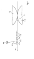
- FIG. 1 shows a schematic representation for explaining the method according to the invention in a printing press.
- a laser light source 10 preferably a diode-pumped, frequency-multiplied solid-state laser, emits light having a wavelength between 350 nm and 700 nm and is arranged within a printing machine such that the light 12 emitted by it strikes a printing material 14 which is on a path 16 through the printing press is moved.
- the orientation of the path 16 is indicated by an arrow.
- the path 16 passes through a printing nip 18 between a printing cylinder 110 and an impression cylinder 112.
- the printing cylinder 110 may be a plate cylinder or a blanket cylinder.
- the printing material 14 is printed with at least one printing ink which has at least one color pigment. While in the FIG. 1 the printing substrate 14 is shown by way of example arcuate, the substrate in an alternative embodiment may also be guided in web form through the printing press along the path 16.
- the path 16 is shown here linearly without limitation of a generally curved or non-linear course, in particular on a circular arc.
- the printing substrate 14 is illuminated at the position 116 of the path 16 with light 12 of the laser light source 10, wherein the light 12 has a wavelength between 350 nm and 700 nm and is substantially resonant to a Absorption wavelength of the color pigment is.
- the light 12 emitted by the laser light source 10 falls on the printing substrate 14 in a bundle-shaped or carpet-like manner at the position 116.
- the ink 114 within the position 116 can absorb energy from the light 12.
- the advantageous selection or tuning of the wavelength of the light 12 according to the invention achieves absorption of the energy by means of the color pigment in the printing ink 14, so that energy for drying the printing ink 14 is introduced directly into the printing ink 14.
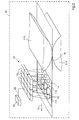
- FIG. 2 is a schematic representation of an advantageous embodiment of a development of the printing unit 30 according to the invention with a number of laser light sources 10 in a printing machine 40. It is a field 20 of laser light sources 10, here three and four, so twelve laser light sources 10 shown. In addition to a two-dimensional field 20, a three-dimensional field or a one-dimensional row oriented over the width of the printing material 14 may be provided. A two-dimensional field, as well as a three-dimensional field whose light strikes substrate 14 in a two-dimensional distribution, has the advantage, inter alia, of achieving rapid drying by irradiating a group of positions in a column of field 20 in parallel or simultaneously.
- Field 20 may also contain a different number of radiant energy sources than shown in FIG FIG. 2 exhibit. From each of the number of laser light sources 10, light 12 is supplied to the printing material 14. The positions 116 at which the light 12 strikes the printing material 14, which follows a path 16 through the printing press, are arranged downstream of a printing gap 118, defined by a printing cylinder 110 and an impression cylinder 112. Individual positions 116 can partially coincide, as in the FIG. 2 for the leading line of radiant energy sources 10, or even substantially completely overlapping.
- the field 20 of radiant energy sources 10 is associated with a control device 24, with which those by means of a connection 22 can exchange control signals.
- a control of the field 20 can be carried out such that a power supply is performed according to the ink quantity at the position 116 on the substrate 14.
- the laser light sources 10 in the field 20 in illumination duration and illumination intensity can be controlled individually.
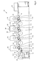
- FIG. 3 schematically shows a printing machine, in this embodiment, a sheet-processing printing machine, with various alternative arrangements of laser light sources in printing units according to the invention.
- the printing press 4 has printing units 30, a feeder 32 and a delivery arm 34.
- various cylinders are shown, which on the one hand serve to guide the sheet through the printing press, on the other hand provide a printing surface available, be it directly as a printing form cylinder or indirectly as a blanket cylinder.
- typical printing units 30 in printing presses 40 further on an inking unit and possibly a dampening unit.
- a printing material passes through the printing machine 40 along the path 16.
- Each printing unit 30 includes a printing cylinder 110 and an impression cylinder 112 which define a printing nip 18 so that the substrate prints at a number of positions (the number of printing nips 18) with a number of different printing colors, each printing ink having at least one different color pigment can be.
- a printing cylinder 110 and an impression cylinder 112 which define a printing nip 18 so that the substrate prints at a number of positions (the number of printing nips 18) with a number of different printing colors, each printing ink having at least one different color pigment can be.
- FIG. 3 Several possibilities are shown, as at at least one further position of the path 16 of the printing material 14 with light of a number of different wavelengths, each one of the different wavelengths is substantially resonant to one of the absorption wavelengths of the different color pigments is illuminated. In concrete embodiments of a printing press one of the possibilities shown can be used in each case for all printing units.
- a first possibility of the arrangement is shown with reference to the first and second printing unit 30: From a central laser light source 36, the emitted light is guided to the printing units 30 associated projection elements 310 by means of light guide elements 38 such as optical fibers, mirrors, imaging optics and the like.
- the projection elements 310 emit light 12 at position 116 on the path 16 of the printing material 14 through the printing press, wherein the positions 116 of the printing material in terms of time after printing with the ink with the color pigment, which is associated with the wavelength of the light 12, passed.
- light-guiding elements 38 it is possible to arrange the laser light source 36 at a suitable location within or adjacent to the printing press 40, in particular the printing unit 30, at which corresponding installation space is available.
- a second possibility of the arrangement is shown with reference to the third and the fourth printing unit 30 with laser light sources 10. Starting from the light sources 10, light 12 is fed directly onto the path 16 of the printing substrate 14. Such a possibility of the arrangement has already in FIG. 1 and FIG. 2 shown topology.
- FIG. 3 also shows a third option for the last printing unit 30:
- the alternative positions 116 may also already be in the boom 34.
- the printing material at a position 116 of the path 16 with light 12 of the number of different wavelengths, the printing with all the number of printing inks can be made temporally downstream.
- printing units according to the invention can also be used in a web-processing printing press, in particular so-called roll-rotary printing machines, be it for commercial or newspaper printing, in an advantageous manner.
Landscapes
- Mechanical Engineering (AREA)
- Health & Medical Sciences (AREA)
- Electromagnetism (AREA)
- General Health & Medical Sciences (AREA)
- Toxicology (AREA)
- Engineering & Computer Science (AREA)
- Physics & Mathematics (AREA)
- Supply, Installation And Extraction Of Printed Sheets Or Plates (AREA)
- Printing Methods (AREA)
- Ink Jet (AREA)
- Coloring (AREA)
- Drying Of Solid Materials (AREA)
- Inks, Pencil-Leads, Or Crayons (AREA)
Applications Claiming Priority (2)
| Application Number | Priority Date | Filing Date | Title |
|---|---|---|---|
| DE10316471A DE10316471A1 (de) | 2003-04-09 | 2003-04-09 | Verfahren zum Trocknen einer Druckfarbe auf einem Bedruckstoff und Druckwerk, geeignet zur Durchführung des Verfahrens |
| DE10316471 | 2003-04-09 |
Publications (3)
| Publication Number | Publication Date |
|---|---|
| EP1466732A2 EP1466732A2 (de) | 2004-10-13 |
| EP1466732A3 EP1466732A3 (de) | 2006-09-27 |
| EP1466732B1 true EP1466732B1 (de) | 2008-05-07 |
Family
ID=32864423
Family Applications (1)
| Application Number | Title | Priority Date | Filing Date |
|---|---|---|---|
| EP04005820A Expired - Lifetime EP1466732B1 (de) | 2003-04-09 | 2004-03-11 | Verfahren zum Trocknen einer Druckfarbe auf einem Bedruckstoff und Druckwerk, geeignet zur Durchführung des Verfahrens |
Country Status (7)
| Country | Link |
|---|---|
| US (1) | US6889608B2 (enExample) |
| EP (1) | EP1466732B1 (enExample) |
| JP (1) | JP4546122B2 (enExample) |
| CN (1) | CN100484759C (enExample) |
| AT (1) | ATE394228T1 (enExample) |
| DE (2) | DE10316471A1 (enExample) |
| DK (1) | DK1466732T3 (enExample) |
Cited By (1)
| Publication number | Priority date | Publication date | Assignee | Title |
|---|---|---|---|---|
| DE102015215335A1 (de) | 2014-10-02 | 2016-04-07 | Heidelberger Druckmaschinen Ag | Vorrichtung und Verfahren zum Auftragen und Bestrahlen von Tinten |
Families Citing this family (10)
| Publication number | Priority date | Publication date | Assignee | Title |
|---|---|---|---|---|
| DE102004020454A1 (de) | 2004-04-27 | 2005-11-24 | Heidelberger Druckmaschinen Ag | Vorrichtung zur Zuführung von Strahlungsenergie auf einen Bedruckstoff |
| US8083338B2 (en) * | 2004-05-06 | 2011-12-27 | Agfa Graphics N.V. | Radiation-curable ink-jet printing |
| DE102005037497A1 (de) * | 2005-08-09 | 2007-02-15 | Man Roland Druckmaschinen Ag | Kennzeichnungssystem und Qualitäts- und Kennzeichnungsverfahren für eine Bogendruckmaschine |
| EP1880846B1 (de) * | 2006-07-18 | 2012-12-19 | Heidelberger Druckmaschinen AG | Bogenoffsetdruckmaschine |
| DE102008013745A1 (de) | 2007-03-29 | 2008-10-02 | Heidelberger Druckmaschinen Ag | Druckfarbe |
| DE102008056237B4 (de) | 2007-12-07 | 2019-04-25 | Heidelberger Druckmaschinen Ag | Verfahren zum Trocknen von Druckfarbe und Druckfarbe |
| US8240841B2 (en) * | 2009-01-03 | 2012-08-14 | David M Caracciolo | Pulse drying system |
| EP3124261B1 (en) * | 2015-07-31 | 2023-06-07 | HP Scitex Ltd | Printer ink dryer units |
| DE102016214721A1 (de) | 2016-08-09 | 2018-02-15 | Heidelberger Druckmaschinen Ag | Tintenstrahl-Druckmaschine mit wenigstens zwei Tintenstrahl-Druckköpfen |
| FR3113860B1 (fr) | 2020-09-07 | 2023-03-03 | Kelenn Tech | Procédé de séchage d’encre et système associé |
Family Cites Families (20)
| Publication number | Priority date | Publication date | Assignee | Title |
|---|---|---|---|---|
| US75063A (en) * | 1868-03-03 | Anthony w | ||
| CH639800A5 (en) * | 1980-11-27 | 1983-11-30 | Sicpa Sa | Device for treating the free surface of the material making up an object by laser irradiation |
| NZ215951A (en) * | 1985-05-14 | 1988-10-28 | Commw Of Australia | Curing polymeric coating film with uv radiation |
| DE3828753C2 (de) * | 1988-08-25 | 1994-05-19 | Heidelberger Druckmasch Ag | Vorrichtung zum Trocknen von Druckprodukten in einer Druckmaschine |
| DE4435077A1 (de) | 1994-09-30 | 1995-11-09 | Siemens Nixdorf Inf Syst | Schnell schaltbare und höchstgeschwindigkeitsfähige Infrarotfixierung elektrografischer Tonerbilder |
| JP3491653B2 (ja) * | 1995-09-29 | 2004-01-26 | 日立プリンティングソリューションズ株式会社 | 静電記録装置および静電記録方法 |
| US5972082A (en) * | 1996-04-30 | 1999-10-26 | Ricoh Company, Ltd. | Aqueous ink composition and ink-jet printing method using the same |
| US5858583A (en) * | 1997-07-03 | 1999-01-12 | E. I. Du Pont De Nemours And Company | Thermally imageable monochrome digital proofing product with high contrast and fast photospeed |
| AU4754697A (en) * | 1997-10-15 | 1999-05-03 | Revlon Consumer Products Corporation | Apparatus and method for screen printing radiation curable compositions |
| US6026748A (en) * | 1997-11-11 | 2000-02-22 | Oxy-Dry Corporation | Infrared dryer system for printing presses |
| JP2000044857A (ja) * | 1998-05-29 | 2000-02-15 | Brother Ind Ltd | 熱溶融性インクおよびインクジェット式記録装置 |
| DE19855940A1 (de) * | 1998-12-04 | 2000-06-08 | Voith Sulzer Papiertech Patent | Faserstoffbahntrocknung |
| US6503691B1 (en) * | 1999-12-17 | 2003-01-07 | Creo Srl | Polymer system with switchable physical properties and its use in direct exposure printing plates |
| US6350071B1 (en) * | 2000-06-21 | 2002-02-26 | Intermec Ip Corp. | On demand printer apparatus and method with integrated UV curing |
| US6482571B1 (en) * | 2000-09-06 | 2002-11-19 | Gary Ganghui Teng | On-press development of thermosensitive lithographic plates |
| US6605407B2 (en) * | 2000-12-26 | 2003-08-12 | Creo Inc. | Thermally convertible lithographic printing precursor |
| DE10107682B4 (de) * | 2001-01-09 | 2005-12-15 | Eastman Kodak Co. | Druck- oder Kopiermaschine |
| US20030235776A1 (en) * | 2002-06-24 | 2003-12-25 | Goodin Jonathan W. | Thermally-convertible lithographic printing precursor and imageable medium with coalescence inhibitor |
| EP1302735B1 (de) * | 2001-10-10 | 2014-01-01 | Heidelberger Druckmaschinen Aktiengesellschaft | Vorrichtung und Verfahren zur Zuführung von Strahlungsenergie auf einen Bedruckstoff in einer Flachdruckmaschine |
| DE10234076A1 (de) * | 2001-10-10 | 2003-04-24 | Heidelberger Druckmasch Ag | Vorrichtung und Verfahren zur Zuführung von Strahlungsenergie auf einem Bedruckstoff in einer Flachdruckmaschine |
-
2003
- 2003-04-09 DE DE10316471A patent/DE10316471A1/de not_active Withdrawn
-
2004
- 2004-03-11 DK DK04005820T patent/DK1466732T3/da active
- 2004-03-11 DE DE502004007026T patent/DE502004007026D1/de not_active Expired - Lifetime
- 2004-03-11 AT AT04005820T patent/ATE394228T1/de not_active IP Right Cessation
- 2004-03-11 EP EP04005820A patent/EP1466732B1/de not_active Expired - Lifetime
- 2004-03-19 JP JP2004080131A patent/JP4546122B2/ja not_active Expired - Fee Related
- 2004-03-31 US US10/815,002 patent/US6889608B2/en not_active Expired - Lifetime
- 2004-04-09 CN CNB2004100334916A patent/CN100484759C/zh not_active Expired - Fee Related
Cited By (1)
| Publication number | Priority date | Publication date | Assignee | Title |
|---|---|---|---|---|
| DE102015215335A1 (de) | 2014-10-02 | 2016-04-07 | Heidelberger Druckmaschinen Ag | Vorrichtung und Verfahren zum Auftragen und Bestrahlen von Tinten |
Also Published As
| Publication number | Publication date |
|---|---|
| ATE394228T1 (de) | 2008-05-15 |
| DK1466732T3 (da) | 2008-08-11 |
| JP2004306598A (ja) | 2004-11-04 |
| DE502004007026D1 (de) | 2008-06-19 |
| EP1466732A3 (de) | 2006-09-27 |
| JP4546122B2 (ja) | 2010-09-15 |
| CN100484759C (zh) | 2009-05-06 |
| CN1541834A (zh) | 2004-11-03 |
| EP1466732A2 (de) | 2004-10-13 |
| US6889608B2 (en) | 2005-05-10 |
| DE10316471A1 (de) | 2004-10-28 |
| US20040200370A1 (en) | 2004-10-14 |
Similar Documents
| Publication | Publication Date | Title |
|---|---|---|
| EP1302735B1 (de) | Vorrichtung und Verfahren zur Zuführung von Strahlungsenergie auf einen Bedruckstoff in einer Flachdruckmaschine | |
| EP1466731B1 (de) | Verfahren zum Trocknen einer Druckfarbe auf einem Bedruckstoff in einer Druckmaschine und Druckmashine | |
| EP2067620B1 (de) | Verfahren zum Trocknen von bedrucktem Material im Mehrfarbdruck | |
| DE10234076A1 (de) | Vorrichtung und Verfahren zur Zuführung von Strahlungsenergie auf einem Bedruckstoff in einer Flachdruckmaschine | |
| EP1591246B1 (de) | Vorrichtung zur Zuführung von Strahlungsenergie auf einen Bedruckstoff | |
| EP0963839B1 (de) | Druckmaschine und Druckverfahren | |
| EP1466732B1 (de) | Verfahren zum Trocknen einer Druckfarbe auf einem Bedruckstoff und Druckwerk, geeignet zur Durchführung des Verfahrens | |
| EP2258553A1 (de) | Vorrichtung und Verfahren zum Trocknen von Farbe auf einem bedruckten Substrat | |
| DE4342643C2 (de) | Erwärmungsarme Fixierung mit Barrierenentladung in Tintenstrahldruckern | |
| EP3281800A1 (de) | Tintenstrahl-druckmaschine mit wenigstens zwei tintenstrahl-druckköpfen | |
| DE102012024393A1 (de) | Verfahren zum indirekten Auftragen von Druckflüssigkeit auf einen Bedruckstoff | |
| DE102017124115B4 (de) | Verfahren und Steuereinheit zur Fixierung eines Druckbildes | |
| DE102020128849A1 (de) | Verfahren und Anordnung zur Herstellung eines bedruckten flächigen Verpackungsmaterials | |
| EP1593513B1 (de) | Druckmaschine mit mindestens zwei jeweils eine Drucksubstanz tragenden Farbträgern | |
| EP3921173A2 (de) | System und verfahren zum zwischentrocknen eines druckmediums | |
| EP4681927A1 (de) | Verfahren zum drucken mit einer inkjetdruckmaschine unter inertgasatmosphäre | |
| DE102010009520A1 (de) | Offsetdruckmaschine und Verfahren zum Betreiben einer Offsetdruckmaschine | |
| HK1070862A (en) | Method for drying a printing ink on a printing substrate, and print unit suited for implementing the method | |
| EP2111652A1 (de) | Verfahren zum übertragen von strukturinformationen und vorrichtung hierfür | |
| DE102022103993A1 (de) | Verfahren zum Härten von Beschichtungen in einer Druckmaschine mittels unterschiedlich angesteuerter Gasentladungslampen | |
| DE102020123695A1 (de) | Vorrichtung zum Bestrahlen eines Fluids auf einem Bedruckstoff | |
| WO2020161277A1 (de) | System und verfahren zum zwischentrocknen eines druckmediums mittels hochfrequenzstrahlung | |
| DE10253745A1 (de) | Verfahren und Vorrichtung zur Vermeidung von Öleintrag in eine Druckmaschine | |
| DE102005029971A1 (de) | Verfahren zum Aufbringen variierbarer Aufdrucke in Druckmaschinen | |
| DE102017107518A1 (de) | Druckvorrichtung mit Mitteln zur bereichsweisen Anpassung eines Glanzeindrucks |
Legal Events
| Date | Code | Title | Description |
|---|---|---|---|
| PUAI | Public reference made under article 153(3) epc to a published international application that has entered the european phase |
Free format text: ORIGINAL CODE: 0009012 |
|
| AK | Designated contracting states |
Kind code of ref document: A2 Designated state(s): AT BE BG CH CY CZ DE DK EE ES FI FR GB GR HU IE IT LI LU MC NL PL PT RO SE SI SK TR |
|
| AX | Request for extension of the european patent |
Extension state: AL LT LV MK |
|
| PUAL | Search report despatched |
Free format text: ORIGINAL CODE: 0009013 |
|
| AK | Designated contracting states |
Kind code of ref document: A3 Designated state(s): AT BE BG CH CY CZ DE DK EE ES FI FR GB GR HU IE IT LI LU MC NL PL PT RO SE SI SK TR |
|
| AX | Request for extension of the european patent |
Extension state: AL LT LV MK |
|
| 17P | Request for examination filed |
Effective date: 20070327 |
|
| AKX | Designation fees paid |
Designated state(s): AT BE BG CH CY CZ DE DK EE ES FI FR GB GR HU IE IT LI LU MC NL PL PT RO SE SI SK TR |
|
| 17Q | First examination report despatched |
Effective date: 20070614 |
|
| GRAP | Despatch of communication of intention to grant a patent |
Free format text: ORIGINAL CODE: EPIDOSNIGR1 |
|
| GRAS | Grant fee paid |
Free format text: ORIGINAL CODE: EPIDOSNIGR3 |
|
| GRAA | (expected) grant |
Free format text: ORIGINAL CODE: 0009210 |
|
| AK | Designated contracting states |
Kind code of ref document: B1 Designated state(s): AT BE BG CH CY CZ DE DK EE ES FI FR GB GR HU IE IT LI LU MC NL PL PT RO SE SI SK TR |
|
| REG | Reference to a national code |
Ref country code: GB Ref legal event code: FG4D Free format text: NOT ENGLISH |
|
| REG | Reference to a national code |
Ref country code: CH Ref legal event code: EP |
|
| REG | Reference to a national code |
Ref country code: IE Ref legal event code: FG4D Free format text: LANGUAGE OF EP DOCUMENT: GERMAN |
|
| REF | Corresponds to: |
Ref document number: 502004007026 Country of ref document: DE Date of ref document: 20080619 Kind code of ref document: P |
|
| REG | Reference to a national code |
Ref country code: DK Ref legal event code: T3 |
|
| PG25 | Lapsed in a contracting state [announced via postgrant information from national office to epo] |
Ref country code: SI Free format text: LAPSE BECAUSE OF FAILURE TO SUBMIT A TRANSLATION OF THE DESCRIPTION OR TO PAY THE FEE WITHIN THE PRESCRIBED TIME-LIMIT Effective date: 20080507 |
|
| PG25 | Lapsed in a contracting state [announced via postgrant information from national office to epo] |
Ref country code: FI Free format text: LAPSE BECAUSE OF FAILURE TO SUBMIT A TRANSLATION OF THE DESCRIPTION OR TO PAY THE FEE WITHIN THE PRESCRIBED TIME-LIMIT Effective date: 20080507 Ref country code: ES Free format text: LAPSE BECAUSE OF FAILURE TO SUBMIT A TRANSLATION OF THE DESCRIPTION OR TO PAY THE FEE WITHIN THE PRESCRIBED TIME-LIMIT Effective date: 20080818 |
|
| PG25 | Lapsed in a contracting state [announced via postgrant information from national office to epo] |
Ref country code: PL Free format text: LAPSE BECAUSE OF FAILURE TO SUBMIT A TRANSLATION OF THE DESCRIPTION OR TO PAY THE FEE WITHIN THE PRESCRIBED TIME-LIMIT Effective date: 20080507 |
|
| REG | Reference to a national code |
Ref country code: IE Ref legal event code: FD4D |
|
| PG25 | Lapsed in a contracting state [announced via postgrant information from national office to epo] |
Ref country code: SE Free format text: LAPSE BECAUSE OF FAILURE TO SUBMIT A TRANSLATION OF THE DESCRIPTION OR TO PAY THE FEE WITHIN THE PRESCRIBED TIME-LIMIT Effective date: 20080807 Ref country code: IE Free format text: LAPSE BECAUSE OF FAILURE TO SUBMIT A TRANSLATION OF THE DESCRIPTION OR TO PAY THE FEE WITHIN THE PRESCRIBED TIME-LIMIT Effective date: 20080507 Ref country code: PT Free format text: LAPSE BECAUSE OF FAILURE TO SUBMIT A TRANSLATION OF THE DESCRIPTION OR TO PAY THE FEE WITHIN THE PRESCRIBED TIME-LIMIT Effective date: 20081007 |
|
| PG25 | Lapsed in a contracting state [announced via postgrant information from national office to epo] |
Ref country code: RO Free format text: LAPSE BECAUSE OF FAILURE TO SUBMIT A TRANSLATION OF THE DESCRIPTION OR TO PAY THE FEE WITHIN THE PRESCRIBED TIME-LIMIT Effective date: 20080507 Ref country code: SK Free format text: LAPSE BECAUSE OF FAILURE TO SUBMIT A TRANSLATION OF THE DESCRIPTION OR TO PAY THE FEE WITHIN THE PRESCRIBED TIME-LIMIT Effective date: 20080507 |
|
| PLBE | No opposition filed within time limit |
Free format text: ORIGINAL CODE: 0009261 |
|
| STAA | Information on the status of an ep patent application or granted ep patent |
Free format text: STATUS: NO OPPOSITION FILED WITHIN TIME LIMIT |
|
| 26N | No opposition filed |
Effective date: 20090210 |
|
| PG25 | Lapsed in a contracting state [announced via postgrant information from national office to epo] |
Ref country code: BG Free format text: LAPSE BECAUSE OF FAILURE TO SUBMIT A TRANSLATION OF THE DESCRIPTION OR TO PAY THE FEE WITHIN THE PRESCRIBED TIME-LIMIT Effective date: 20080807 Ref country code: EE Free format text: LAPSE BECAUSE OF FAILURE TO SUBMIT A TRANSLATION OF THE DESCRIPTION OR TO PAY THE FEE WITHIN THE PRESCRIBED TIME-LIMIT Effective date: 20080507 |
|
| BERE | Be: lapsed |
Owner name: HEIDELBERGER DRUCKMASCHINEN A.G. Effective date: 20090331 |
|
| PG25 | Lapsed in a contracting state [announced via postgrant information from national office to epo] |
Ref country code: MC Free format text: LAPSE BECAUSE OF NON-PAYMENT OF DUE FEES Effective date: 20090331 |
|
| PG25 | Lapsed in a contracting state [announced via postgrant information from national office to epo] |
Ref country code: BE Free format text: LAPSE BECAUSE OF NON-PAYMENT OF DUE FEES Effective date: 20090331 |
|
| PG25 | Lapsed in a contracting state [announced via postgrant information from national office to epo] |
Ref country code: AT Free format text: LAPSE BECAUSE OF NON-PAYMENT OF DUE FEES Effective date: 20090311 |
|
| PG25 | Lapsed in a contracting state [announced via postgrant information from national office to epo] |
Ref country code: GR Free format text: LAPSE BECAUSE OF FAILURE TO SUBMIT A TRANSLATION OF THE DESCRIPTION OR TO PAY THE FEE WITHIN THE PRESCRIBED TIME-LIMIT Effective date: 20080808 |
|
| PG25 | Lapsed in a contracting state [announced via postgrant information from national office to epo] |
Ref country code: LU Free format text: LAPSE BECAUSE OF NON-PAYMENT OF DUE FEES Effective date: 20090311 |
|
| PGFP | Annual fee paid to national office [announced via postgrant information from national office to epo] |
Ref country code: DK Payment date: 20110324 Year of fee payment: 8 |
|
| PGFP | Annual fee paid to national office [announced via postgrant information from national office to epo] |
Ref country code: CZ Payment date: 20110222 Year of fee payment: 8 |
|
| PG25 | Lapsed in a contracting state [announced via postgrant information from national office to epo] |
Ref country code: HU Free format text: LAPSE BECAUSE OF FAILURE TO SUBMIT A TRANSLATION OF THE DESCRIPTION OR TO PAY THE FEE WITHIN THE PRESCRIBED TIME-LIMIT Effective date: 20081108 |
|
| PG25 | Lapsed in a contracting state [announced via postgrant information from national office to epo] |
Ref country code: TR Free format text: LAPSE BECAUSE OF FAILURE TO SUBMIT A TRANSLATION OF THE DESCRIPTION OR TO PAY THE FEE WITHIN THE PRESCRIBED TIME-LIMIT Effective date: 20080507 |
|
| PG25 | Lapsed in a contracting state [announced via postgrant information from national office to epo] |
Ref country code: CY Free format text: LAPSE BECAUSE OF FAILURE TO SUBMIT A TRANSLATION OF THE DESCRIPTION OR TO PAY THE FEE WITHIN THE PRESCRIBED TIME-LIMIT Effective date: 20080507 |
|
| PGFP | Annual fee paid to national office [announced via postgrant information from national office to epo] |
Ref country code: IT Payment date: 20120322 Year of fee payment: 9 |
|
| PG25 | Lapsed in a contracting state [announced via postgrant information from national office to epo] |
Ref country code: CZ Free format text: LAPSE BECAUSE OF NON-PAYMENT OF DUE FEES Effective date: 20120311 |
|
| REG | Reference to a national code |
Ref country code: DK Ref legal event code: EBP |
|
| PG25 | Lapsed in a contracting state [announced via postgrant information from national office to epo] |
Ref country code: DK Free format text: LAPSE BECAUSE OF NON-PAYMENT OF DUE FEES Effective date: 20120331 |
|
| PGFP | Annual fee paid to national office [announced via postgrant information from national office to epo] |
Ref country code: NL Payment date: 20130321 Year of fee payment: 10 |
|
| REG | Reference to a national code |
Ref country code: NL Ref legal event code: V1 Effective date: 20141001 |
|
| PG25 | Lapsed in a contracting state [announced via postgrant information from national office to epo] |
Ref country code: NL Free format text: LAPSE BECAUSE OF NON-PAYMENT OF DUE FEES Effective date: 20141001 |
|
| REG | Reference to a national code |
Ref country code: FR Ref legal event code: PLFP Year of fee payment: 12 |
|
| PG25 | Lapsed in a contracting state [announced via postgrant information from national office to epo] |
Ref country code: IT Free format text: LAPSE BECAUSE OF NON-PAYMENT OF DUE FEES Effective date: 20140311 |
|
| REG | Reference to a national code |
Ref country code: FR Ref legal event code: PLFP Year of fee payment: 13 |
|
| REG | Reference to a national code |
Ref country code: DE Ref legal event code: R081 Ref document number: 502004007026 Country of ref document: DE Owner name: HEIDELBERGER DRUCKMASCHINEN AG, DE Free format text: FORMER OWNER: HEIDELBERGER DRUCKMASCHINEN AKTIENGESELLSCHAFT, 69115 HEIDELBERG, DE |
|
| REG | Reference to a national code |
Ref country code: FR Ref legal event code: PLFP Year of fee payment: 14 |
|
| PGFP | Annual fee paid to national office [announced via postgrant information from national office to epo] |
Ref country code: CH Payment date: 20170323 Year of fee payment: 14 Ref country code: FR Payment date: 20170323 Year of fee payment: 14 |
|
| PGFP | Annual fee paid to national office [announced via postgrant information from national office to epo] |
Ref country code: GB Payment date: 20170323 Year of fee payment: 14 |
|
| REG | Reference to a national code |
Ref country code: CH Ref legal event code: PL |
|
| GBPC | Gb: european patent ceased through non-payment of renewal fee |
Effective date: 20180311 |
|
| PG25 | Lapsed in a contracting state [announced via postgrant information from national office to epo] |
Ref country code: GB Free format text: LAPSE BECAUSE OF NON-PAYMENT OF DUE FEES Effective date: 20180311 Ref country code: LI Free format text: LAPSE BECAUSE OF NON-PAYMENT OF DUE FEES Effective date: 20180331 Ref country code: CH Free format text: LAPSE BECAUSE OF NON-PAYMENT OF DUE FEES Effective date: 20180331 |
|
| PG25 | Lapsed in a contracting state [announced via postgrant information from national office to epo] |
Ref country code: FR Free format text: LAPSE BECAUSE OF NON-PAYMENT OF DUE FEES Effective date: 20180331 |
|
| PGFP | Annual fee paid to national office [announced via postgrant information from national office to epo] |
Ref country code: DE Payment date: 20210331 Year of fee payment: 18 |
|
| REG | Reference to a national code |
Ref country code: DE Ref legal event code: R119 Ref document number: 502004007026 Country of ref document: DE |
|
| PG25 | Lapsed in a contracting state [announced via postgrant information from national office to epo] |
Ref country code: DE Free format text: LAPSE BECAUSE OF NON-PAYMENT OF DUE FEES Effective date: 20221001 |