EP1466732B1 - Process for drying printing colour on a printing substrate, and printing unit adapted for carrying out the process - Google Patents
Process for drying printing colour on a printing substrate, and printing unit adapted for carrying out the process Download PDFInfo
- Publication number
- EP1466732B1 EP1466732B1 EP04005820A EP04005820A EP1466732B1 EP 1466732 B1 EP1466732 B1 EP 1466732B1 EP 04005820 A EP04005820 A EP 04005820A EP 04005820 A EP04005820 A EP 04005820A EP 1466732 B1 EP1466732 B1 EP 1466732B1
- Authority
- EP
- European Patent Office
- Prior art keywords
- printing
- substrate
- light
- wavelength
- laser light
- Prior art date
- Legal status (The legal status is an assumption and is not a legal conclusion. Google has not performed a legal analysis and makes no representation as to the accuracy of the status listed.)
- Expired - Lifetime
Links
- 238000007639 printing Methods 0.000 title claims abstract description 261
- 238000001035 drying Methods 0.000 title claims abstract description 32
- 239000000758 substrate Substances 0.000 title claims description 56
- 238000000034 method Methods 0.000 title claims description 30
- 239000000976 ink Substances 0.000 claims abstract description 74
- 238000010521 absorption reaction Methods 0.000 claims description 43
- 239000000049 pigment Substances 0.000 claims description 41
- 239000000463 material Substances 0.000 claims description 27
- XLYOFNOQVPJJNP-UHFFFAOYSA-N water Substances O XLYOFNOQVPJJNP-UHFFFAOYSA-N 0.000 claims description 9
- 238000005286 illumination Methods 0.000 claims description 5
- 239000004065 semiconductor Substances 0.000 claims description 4
- 239000003086 colorant Substances 0.000 abstract description 3
- 239000004033 plastic Substances 0.000 abstract 2
- 229920003023 plastic Polymers 0.000 abstract 2
- 239000002904 solvent Substances 0.000 description 14
- 230000005855 radiation Effects 0.000 description 11
- 238000011161 development Methods 0.000 description 7
- 230000018109 developmental process Effects 0.000 description 7
- 239000000123 paper Substances 0.000 description 6
- 238000012545 processing Methods 0.000 description 6
- 239000000126 substance Substances 0.000 description 5
- 239000006096 absorbing agent Substances 0.000 description 4
- 230000000694 effects Effects 0.000 description 4
- 238000010438 heat treatment Methods 0.000 description 4
- 238000007645 offset printing Methods 0.000 description 4
- 230000003595 spectral effect Effects 0.000 description 4
- 239000011230 binding agent Substances 0.000 description 3
- 238000003384 imaging method Methods 0.000 description 3
- 239000002245 particle Substances 0.000 description 3
- 238000006116 polymerization reaction Methods 0.000 description 3
- 239000011347 resin Substances 0.000 description 3
- 229920005989 resin Polymers 0.000 description 3
- 238000011144 upstream manufacturing Methods 0.000 description 3
- 239000005371 ZBLAN Substances 0.000 description 2
- 230000001419 dependent effect Effects 0.000 description 2
- 238000001704 evaporation Methods 0.000 description 2
- 230000008020 evaporation Effects 0.000 description 2
- 239000011521 glass Substances 0.000 description 2
- 238000000926 separation method Methods 0.000 description 2
- 230000001960 triggered effect Effects 0.000 description 2
- FOXXZZGDIAQPQI-XKNYDFJKSA-N Asp-Pro-Ser-Ser Chemical compound OC(=O)C[C@H](N)C(=O)N1CCC[C@H]1C(=O)N[C@@H](CO)C(=O)N[C@@H](CO)C(O)=O FOXXZZGDIAQPQI-XKNYDFJKSA-N 0.000 description 1
- 229910052691 Erbium Inorganic materials 0.000 description 1
- RTAQQCXQSZGOHL-UHFFFAOYSA-N Titanium Chemical compound [Ti] RTAQQCXQSZGOHL-UHFFFAOYSA-N 0.000 description 1
- 238000000862 absorption spectrum Methods 0.000 description 1
- 238000013459 approach Methods 0.000 description 1
- XKRFYHLGVUSROY-UHFFFAOYSA-N argon Substances [Ar] XKRFYHLGVUSROY-UHFFFAOYSA-N 0.000 description 1
- 229910052786 argon Inorganic materials 0.000 description 1
- -1 argon ions Chemical class 0.000 description 1
- QVGXLLKOCUKJST-UHFFFAOYSA-N atomic oxygen Chemical compound [O] QVGXLLKOCUKJST-UHFFFAOYSA-N 0.000 description 1
- 238000006243 chemical reaction Methods 0.000 description 1
- 239000011248 coating agent Substances 0.000 description 1
- 238000000576 coating method Methods 0.000 description 1
- 239000000470 constituent Substances 0.000 description 1
- XCJYREBRNVKWGJ-UHFFFAOYSA-N copper(II) phthalocyanine Chemical compound [Cu+2].C12=CC=CC=C2C(N=C2[N-]C(C3=CC=CC=C32)=N2)=NC1=NC([C]1C=CC=CC1=1)=NC=1N=C1[C]3C=CC=CC3=C2[N-]1 XCJYREBRNVKWGJ-UHFFFAOYSA-N 0.000 description 1
- 230000008878 coupling Effects 0.000 description 1
- 238000010168 coupling process Methods 0.000 description 1
- 238000005859 coupling reaction Methods 0.000 description 1
- 238000000354 decomposition reaction Methods 0.000 description 1
- 238000009792 diffusion process Methods 0.000 description 1
- 230000005670 electromagnetic radiation Effects 0.000 description 1
- 238000000295 emission spectrum Methods 0.000 description 1
- 238000005516 engineering process Methods 0.000 description 1
- UYAHIZSMUZPPFV-UHFFFAOYSA-N erbium Chemical compound [Er] UYAHIZSMUZPPFV-UHFFFAOYSA-N 0.000 description 1
- 239000005383 fluoride glass Substances 0.000 description 1
- 238000009472 formulation Methods 0.000 description 1
- 239000007789 gas Substances 0.000 description 1
- 238000009434 installation Methods 0.000 description 1
- 230000001678 irradiating effect Effects 0.000 description 1
- 239000000203 mixture Substances 0.000 description 1
- 239000003921 oil Substances 0.000 description 1
- 230000003287 optical effect Effects 0.000 description 1
- 239000013307 optical fiber Substances 0.000 description 1
- 238000013021 overheating Methods 0.000 description 1
- 230000001590 oxidative effect Effects 0.000 description 1
- 239000001301 oxygen Substances 0.000 description 1
- 229910052760 oxygen Inorganic materials 0.000 description 1
- 239000003973 paint Substances 0.000 description 1
- 230000001846 repelling effect Effects 0.000 description 1
- 229910052594 sapphire Inorganic materials 0.000 description 1
- 239000010980 sapphire Substances 0.000 description 1
- 238000007650 screen-printing Methods 0.000 description 1
- 239000007787 solid Substances 0.000 description 1
- 230000002123 temporal effect Effects 0.000 description 1
- 229910052719 titanium Inorganic materials 0.000 description 1
- 239000010936 titanium Substances 0.000 description 1
- 239000002918 waste heat Substances 0.000 description 1
Images
Classifications
-
- B—PERFORMING OPERATIONS; TRANSPORTING
- B41—PRINTING; LINING MACHINES; TYPEWRITERS; STAMPS
- B41F—PRINTING MACHINES OR PRESSES
- B41F23/00—Devices for treating the surfaces of sheets, webs, or other articles in connection with printing
- B41F23/04—Devices for treating the surfaces of sheets, webs, or other articles in connection with printing by heat drying, by cooling, by applying powders
- B41F23/044—Drying sheets, e.g. between two printing stations
-
- B—PERFORMING OPERATIONS; TRANSPORTING
- B41—PRINTING; LINING MACHINES; TYPEWRITERS; STAMPS
- B41M—PRINTING, DUPLICATING, MARKING, OR COPYING PROCESSES; COLOUR PRINTING
- B41M7/00—After-treatment of prints, e.g. heating, irradiating, setting of the ink, protection of the printed stock
- B41M7/0081—After-treatment of prints, e.g. heating, irradiating, setting of the ink, protection of the printed stock using electromagnetic radiation or waves, e.g. ultraviolet radiation, electron beams
Definitions
- the invention relates to a method for drying a printing ink on a substrate in a printing machine, wherein the substrate is printed at a position of a path along which the substrate is moved by the printing press, with at least one ink with at least one color pigment and wherein temporally downstream of the Substrate is illuminated at least one further position of the path with light from a laser light source. Furthermore, the invention relates to a printing unit with a laser light source for carrying out the method.
- planographic printing machines such as lithographic printing machines, rotary printing machines, offset printing machines, flexo printing machines and the like, which arcuate or web-shaped substrates, especially paper, cardboard, cardboard and the like, which are known to initiate or assist adhesion of the ink to the printing material by supplying radiant energy, in particular in the form of light, to the printing ink present on the printing substrate.
- UV inks cure by polymerization, which is triggered by photo-initiation by means of light in the ultraviolet.
- solvent-based printing inks which can undergo both a physical and a chemical drying process, are widely used.
- the physical drying comprises the evaporation of solvents and the diffusion into the printing material (knocking off), while chemical drying or oxidative drying due to polymerization of the oils, resins, binders or the like contained in the paint formulations is possibly understood to mean the presence of atmospheric oxygen.
- the drying processes are generally dependent on each other, since the separation of the solvents causes a separation within the binder system between solvents and resins, as a result of which the resin molecules can approach and possibly polymerize more easily.
- a device for drying printed products which comprises a radiation energy source in the form of a laser.
- the radiant energy is conducted to the surface of the substrates, which move on a web by means of a transport device through the printing press, at a position between individual printing units or after the last printing unit before or in the boom.
- the radiation source may be a laser in the ultraviolet for UV inks or a laser light source for heating solvent-based inks.
- the source of radiation energy is located outside the printing press to avoid undesirable heating of parts of the printing press due to unavoidable or shieldable waste heat.
- an additional system component for the printing press must be provided separately.
- an electrophotographic printing machine or copying machine has a plurality of toner fixing devices wherein each of the fixing means emits a wavelength range of electromagnetic radiation which corresponds to a maximum absorption wavelength of the toner species associated with this fixing means but has no or only slight absorption at absorption wavelengths of the other types of toner.
- solvent-based printing ink refers in particular to colors whose solvent constituents may be of aqueous or organic nature, which build up on binder systems which can be polymerized oxidatively, ionically or radically.
- An energy input for drying of solvent-based printing inks should support or promote the effect of evaporation of the solvent and / or the effect of repelling the substrate and / or the effect of the polymerization, while undesirable side effects, such as in particular excessive heating of the solvent-containing printing ink, which can lead to decomposition of components or overheating of the solvent can be avoided.
- the energy input should not only be introduced to melt particles, as in the case of toner fixation.
- an ink to be printed in a printing unit is incorporated with an infrared absorber - a substance which absorbs in the near infrared spectral range.
- an infrared absorber a substance which absorbs in the near infrared spectral range.
- a narrow-band radiant energy source arranged downstream of the printing gap, preferably a laser light source
- the printing ink is illuminated on the printing substrate.
- the application of light of a wavelength which is substantially resonant to an absorption wavelength of the infrared absorber causes, enables or promotes an energy input into the ink such that the ink is dried.
- the wavelength of the radiation energy source and the absorption wavelength of the infrared absorber are chosen such that at the same time the wavelength used is non-resonant to water, so that the energy input is reduced or avoided in the substrate.
- the object of the present invention is to provide a method for drying printing ink in a printing machine by means of light from a narrow-band radiation energy source, in which the admixture of an infrared absorber substance to be printed Printing inks can be dispensed with. Furthermore, a printing unit, suitable for carrying out this method should be created.
- the printing material is moved along a path through the printing press.
- the printing substrate is printed with at least one printing ink, in particular an offset printing ink having at least one color pigment.
- the printing material is illuminated at least at a further position of the path with light from a narrow-band radiation energy source, a laser light source, the light having a wavelength, in particular only one wavelength, between 350 nm and 700 nm, which is substantially resonant to an absorption wavelength of the at least one color pigment is the at least one printing ink.
- Narrow-band means that the light source emits only wavelengths ⁇ 20.0 nm, preferably ⁇ 10.0 nm, in particular ⁇ 2 nm, or even only a spectroscopically narrow line around a central wavelength.
- a laser light source emitting light of a wavelength between 350 nm and 700 nm is used or used, the light being substantially resonant to an absorption wavelength of the at least one color pigment of the at least one printing ink. In this way an efficient and fast drying is possible. On Infrarotabsorberstoffe in the color can be omitted.
- the inventive method is based on the finding that the very good absorption capacity of color pigments, in particular common standard pigments, which are used in printing inks, especially offset inks, for coupling an energy input in the form of light in the ink layer of a freshly printed with a printing substrate can be exploited.
- the absorption of the radiation energy is supported, enabled, effected or at least accelerated by the at least one color pigment in the ink.
- An influence on the drying process is achieved by the resulting heat. Possibly. be through the generated heat triggered chemical reactions.
- special laser light sources which emit light at this particular wavelength can be used.
- the wavelength of the light used is between 450 nm and 750 nm.
- Color pigments of conventional offset printing inks (standard: cyan C, magenta M, yellow Y and black K) absorb very well between 350 nm and 700 nm 400 nm to 500 nm typically the printing inks C, M, Y, K, at 400 nm to 600 nm C, M, K and at 400 nm to 750 nm C and K.
- the absorption maxima are as follows: C (Clariant standard pigment Blue 15: 3) 650 ⁇ 100 nm at low absorption even below 550 nm to 400 nm, M (Clariant Standard Pigment Red 57: 1) 500 ⁇ 100 nm, and Y (Clariant Standard Pigment Yellow 13) 400 ⁇ 100 nm
- C Clariant standard pigment Blue 15: 3
- M Clariant Standard Pigment Red 57: 1
- Y Clariant Standard Pigment Yellow 13
- the absorption by water is less than 10%, in a preferred embodiment less than 1%, preferably less than 0.1%.
- the radiant energy source emits a wavelength corresponding to the absorption of the color pigment, ie, the light emitted by the radiant energy source is preferably substantially resonant or quasi-resonant , in particular resonantly to an absorption wavelength, in particular of the absorption maximum, of the color pigment, so that the best possible agreement of the absorption of the color pigment with the emission maximum of the laser light source is achieved
- a color pigment can have one or more local absorption maxima
- the light emitted is substantially resonant to an absorption wavelength of the color pigment when the wavelength of the light is at least in the flank of the (spectroscopic) absorption line of the color pigment. At least the absorption wavelength and wavelength should differ less than +/- 50 nm.
- the wavelength of the light may be non-resonant to the absorption wavelengths of water (H 2 O).
- the absorption of the radiation energy by water at 20 ° C is not greater than 10.0%, in a preferred embodiment not more than 1.0%, in particular less than 0.1% .
- the narrowband radiant energy source in particular the laser light source, can only emit a very low intensity of light, preferably no light which is resonant to absorption wavelengths of water.
- the method according to the invention can be used with particular advantage for a number of printing inks to be printed: at a number of positions along the path through the printing press, the printing substrate is printed with a number of different printing inks, each of the printing inks having at least one different color pigment. At least at a further position of the path, the substrate is illuminated with light of a number of different wavelengths, one of the different wavelengths being substantially resonant to one of the absorption wavelengths of the different color pigments.
- the inventive method can be used for a number of printing inks in multi-color printing, wherein in each case one resonant wavelength for a color pigment in each case one of the printing inks used is used.
- the printing material can be illuminated at a number of further positions of the path with light of a number of different wavelengths, wherein the illumination of the printing material with a wavelength temporally downstream of the printing with one of the number of printing inks to whose color pigment the wavelength is substantially resonant, and temporally upstream of the printing with another of the number of printing inks, which is not yet printed, takes place.
- a lighting of the printing material with light of a wavelength which is substantially resonant to an absorption wavelength of a colored pigment take place at a position which is the position at which the ink is brought with the color pigment on the substrate, and another position, on which another ink with a further color pigment is printed on the substrate upstream.
- the substrate may be illuminated in temporal succession with printing with the number of different inks.
- the substrate passes on its path through the printing machine, the number of positions at which the number of printing inks are applied before irradiation of the substrate with light of the number of wavelengths.
- a relatively high energy input directly into the printing ink, supported by the absorption capacity of the color pigment or pigments, is advantageously possible without obtaining an undesired introduction of energy into the printing substrate.
- the required total energy supply is reduced.
- the absorption of the radiation energy in the printing ink is more than 30%, preferably 50%, in particular 75%, may even be more than 90%.
- a printing unit with at least one laser light source which associated with the printing unit, in particular along the path of the printing material through the printing unit downstream of the printing nip is.
- the printing unit according to the invention is suitable for carrying out the method according to the invention in accordance with this illustration, the light of the laser light source having a wavelength between 350 nm and 700 nm in order to achieve the narrowest possible emission with simultaneously high spectral power density.
- the laser light source is preferably a semiconductor laser (diode laser, quantum well laser, InGaAsP laser), a gas laser (HeNe, argon ions), a solid-state laser (titanium sapphire, erbium glass, Nd: YAG, (Nd glass, Nd: YVO 4 , Pr: ZBLAN, Yb: ZBLAN (PR laser, Y-doped fluoride glass laser) or the like), a diode pumped frequency multiplied solid state laser (DPSS), or a frequency multiplied semiconductor laser
- the wavelength of the laser light source is advantageously 450 nm +/- 50 nm, 500 +/- 100 nm, 525 nm +/- 75 nm, 550 nm +/- 50 nm, 600 nm +/- 150 nm, 600 + / - 100 nm or 600 nm +/- 50 nm.
- the central wavelength of the laser emission preferably with spectroscopically narrow line width, can be: 430 nm +/- 50 nm, 442 nm +/- 50 nm, 457 nm +/- 50 nm, 473 nm +/- 50 nm or 532 nm +/- 50 nm.
- such lasers can au to a limited extent be tunable.
- the output wavelength of the lasers can be changeable.
- a tuning to a desired wavelength for example in resonance or quasi-resonance to an absorption wavelength of a color pigment in the printing ink can be achieved.
- an imaging optics can be arranged, the imaging optics of generating an expanded or focused light beam, in particular light cone served on the printing substrate.
- the printing unit according to the invention comprises a number of laser light sources, which are arranged in a one-dimensional, in a two-dimensional field (locally curved, globally curved or flat) or in a three-dimensional field, and their light at a number of positions on the Substrate hits.
- the supply of radiation energy per area is between 100 and 10,000 mJ per cm 2 , preferably between 100 and 1,000 mJ per cm 2 , in particular between 200 and 500 mJ per cm 2 .
- the irradiation of the printing material takes place for a period of time between 0.01 ms and 1 s, preferably 0.1 ms and 100 ms, preferably between 1 ms and 10 ms.
- the light striking the printing material at one position is controllable in its intensity and exposure duration for each laser light source independently of the other laser light sources.
- a control unit independent of or integrated into the machine control of the printing press, may be provided.
- By controlling the laser light source parameters it is possible to regulate the energy supply at different positions of the printing material.
- An energy supply can then be adapted to the coverage of the printing substrate at the present positions on the printing substrate.
- a printing press according to the invention is characterized by at least one printing unit with a laser light source according to this representation.
- a printing machine according to the invention with at least two printing units can be characterized in that the downstream printing unit with a number of laser light sources for carrying out the development of the method applied to a number of printing inks to be printed according to this illustration, wherein the light of the laser light sources a Number of wavelengths which are between 350 nm and 700 nm.
- the printing press is a sheet-fed printing press, the laser light source or the number of laser light sources of the downstream printing unit can already be in the boom.
- the printing press cantilever may comprise a number of laser light sources suitable for performing the method of this drawing, wherein the laser light sources emit a number of wavelengths ranging from 350 nm to 700 nm.
- the printing machine according to the invention may be a direct or indirect planographic printing machine, lithographic printing machine, offset printing machine, flexo printing machine or the like.
- the position at which the light strikes the printing substrate in the path through the printing press can be arranged downstream of the last printing nip of the last printing unit of the number of printing units, that is, all printing nips.
- the position can also be arranged downstream of a first printing nip and arranged upstream of a second printing nip, that is to say at least between two printing units.
- the printing press may be a sheet-fed or a web-processing press.
- a sheet-processing printing machine may include a feeder, at least one printing unit, possibly a finishing plant (stamping, coating unit or the like) and a boom.
- a web-processing printing press may comprise a roll changer, a number of printing units printed on both sides of the printing material web, a dryer and a folding apparatus.
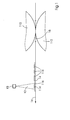
- FIG. 1 shows a schematic representation for explaining the method according to the invention in a printing press.
- a laser light source 10 preferably a diode-pumped, frequency-multiplied solid-state laser, emits light having a wavelength between 350 nm and 700 nm and is arranged within a printing machine such that the light 12 emitted by it strikes a printing material 14 which is on a path 16 through the printing press is moved.
- the orientation of the path 16 is indicated by an arrow.
- the path 16 passes through a printing nip 18 between a printing cylinder 110 and an impression cylinder 112.
- the printing cylinder 110 may be a plate cylinder or a blanket cylinder.
- the printing material 14 is printed with at least one printing ink which has at least one color pigment. While in the FIG. 1 the printing substrate 14 is shown by way of example arcuate, the substrate in an alternative embodiment may also be guided in web form through the printing press along the path 16.
- the path 16 is shown here linearly without limitation of a generally curved or non-linear course, in particular on a circular arc.
- the printing substrate 14 is illuminated at the position 116 of the path 16 with light 12 of the laser light source 10, wherein the light 12 has a wavelength between 350 nm and 700 nm and is substantially resonant to a Absorption wavelength of the color pigment is.
- the light 12 emitted by the laser light source 10 falls on the printing substrate 14 in a bundle-shaped or carpet-like manner at the position 116.
- the ink 114 within the position 116 can absorb energy from the light 12.
- the advantageous selection or tuning of the wavelength of the light 12 according to the invention achieves absorption of the energy by means of the color pigment in the printing ink 14, so that energy for drying the printing ink 14 is introduced directly into the printing ink 14.
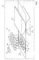
- FIG. 2 is a schematic representation of an advantageous embodiment of a development of the printing unit 30 according to the invention with a number of laser light sources 10 in a printing machine 40. It is a field 20 of laser light sources 10, here three and four, so twelve laser light sources 10 shown. In addition to a two-dimensional field 20, a three-dimensional field or a one-dimensional row oriented over the width of the printing material 14 may be provided. A two-dimensional field, as well as a three-dimensional field whose light strikes substrate 14 in a two-dimensional distribution, has the advantage, inter alia, of achieving rapid drying by irradiating a group of positions in a column of field 20 in parallel or simultaneously.
- Field 20 may also contain a different number of radiant energy sources than shown in FIG FIG. 2 exhibit. From each of the number of laser light sources 10, light 12 is supplied to the printing material 14. The positions 116 at which the light 12 strikes the printing material 14, which follows a path 16 through the printing press, are arranged downstream of a printing gap 118, defined by a printing cylinder 110 and an impression cylinder 112. Individual positions 116 can partially coincide, as in the FIG. 2 for the leading line of radiant energy sources 10, or even substantially completely overlapping.
- the field 20 of radiant energy sources 10 is associated with a control device 24, with which those by means of a connection 22 can exchange control signals.
- a control of the field 20 can be carried out such that a power supply is performed according to the ink quantity at the position 116 on the substrate 14.
- the laser light sources 10 in the field 20 in illumination duration and illumination intensity can be controlled individually.
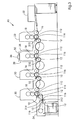
- FIG. 3 schematically shows a printing machine, in this embodiment, a sheet-processing printing machine, with various alternative arrangements of laser light sources in printing units according to the invention.
- the printing press 4 has printing units 30, a feeder 32 and a delivery arm 34.
- various cylinders are shown, which on the one hand serve to guide the sheet through the printing press, on the other hand provide a printing surface available, be it directly as a printing form cylinder or indirectly as a blanket cylinder.
- typical printing units 30 in printing presses 40 further on an inking unit and possibly a dampening unit.
- a printing material passes through the printing machine 40 along the path 16.
- Each printing unit 30 includes a printing cylinder 110 and an impression cylinder 112 which define a printing nip 18 so that the substrate prints at a number of positions (the number of printing nips 18) with a number of different printing colors, each printing ink having at least one different color pigment can be.
- a printing cylinder 110 and an impression cylinder 112 which define a printing nip 18 so that the substrate prints at a number of positions (the number of printing nips 18) with a number of different printing colors, each printing ink having at least one different color pigment can be.
- FIG. 3 Several possibilities are shown, as at at least one further position of the path 16 of the printing material 14 with light of a number of different wavelengths, each one of the different wavelengths is substantially resonant to one of the absorption wavelengths of the different color pigments is illuminated. In concrete embodiments of a printing press one of the possibilities shown can be used in each case for all printing units.
- a first possibility of the arrangement is shown with reference to the first and second printing unit 30: From a central laser light source 36, the emitted light is guided to the printing units 30 associated projection elements 310 by means of light guide elements 38 such as optical fibers, mirrors, imaging optics and the like.
- the projection elements 310 emit light 12 at position 116 on the path 16 of the printing material 14 through the printing press, wherein the positions 116 of the printing material in terms of time after printing with the ink with the color pigment, which is associated with the wavelength of the light 12, passed.
- light-guiding elements 38 it is possible to arrange the laser light source 36 at a suitable location within or adjacent to the printing press 40, in particular the printing unit 30, at which corresponding installation space is available.
- a second possibility of the arrangement is shown with reference to the third and the fourth printing unit 30 with laser light sources 10. Starting from the light sources 10, light 12 is fed directly onto the path 16 of the printing substrate 14. Such a possibility of the arrangement has already in FIG. 1 and FIG. 2 shown topology.
- FIG. 3 also shows a third option for the last printing unit 30:
- the alternative positions 116 may also already be in the boom 34.
- the printing material at a position 116 of the path 16 with light 12 of the number of different wavelengths, the printing with all the number of printing inks can be made temporally downstream.
- printing units according to the invention can also be used in a web-processing printing press, in particular so-called roll-rotary printing machines, be it for commercial or newspaper printing, in an advantageous manner.
Abstract
Description
Die Erfindung betrifft ein Verfahren zum Trocknen einer Druckfarbe auf einem Bedruckstoff in einer Druckmaschine, wobei der Bedruckstoff an einer Position eines Pfades, entlang welchem der Bedruckstoff durch die Druckmaschine bewegt wird, mit wenigsten einer Druckfarbe mit wenigstens einem Farbpigment bedruckt wird und wobei zeitlich nachgeordnet der Bedruckstoff an wenigstens einer weiteren Position des Pfades mit Licht einer Laserlichtquelle beleuchtet wird. Des weiteren betrifft die Erfindung ein Druckwerk mit einer Laserlichtquelle für die Durchführung des Verfahrens.The invention relates to a method for drying a printing ink on a substrate in a printing machine, wherein the substrate is printed at a position of a path along which the substrate is moved by the printing press, with at least one ink with at least one color pigment and wherein temporally downstream of the Substrate is illuminated at least one further position of the path with light from a laser light source. Furthermore, the invention relates to a printing unit with a laser light source for carrying out the method.
In Abhängigkeit von der Art der Druckfarbe und dem zugrunde liegenden speziellen Trocknungsprozess sind verschiedene Vorrichtungen an Druckmaschinen, insbesondere Flachdruckmaschinen, wie lithographischen Druckmaschinen, Rotationsdruckmaschinen, Offset-Druckmaschinen, Flexo-Druckmaschinen und dergleichen, welche bogenförmige oder bahnförmige Bedruckstoffe, insbesondere Papier, Pappe, Karton und dergleichen, verarbeiten, bekannt, welche eine Haftung der Farbe auf dem Bedruckstoff auslösen oder unterstützen, indem Strahlungsenergie, insbesondere in Form von Licht, der auf dem Bedruckstoff befindlichen Druckfarbe zugeführt wird.Depending on the type of printing ink and the underlying special drying process are various devices on printing machines, especially planographic printing machines, such as lithographic printing machines, rotary printing machines, offset printing machines, flexo printing machines and the like, which arcuate or web-shaped substrates, especially paper, cardboard, cardboard and the like, which are known to initiate or assist adhesion of the ink to the printing material by supplying radiant energy, in particular in the form of light, to the printing ink present on the printing substrate.
Die sogenannten UV-Farben härten durch Polymerisation, welche durch Foto-Initiation mittels Licht im Ultraviolett ausgelöst wird, aus. Dagegen existieren in weiter Verbreitung lösemittelhaltige Druckfarben, welche sowohl einem physikalischen als auch einem chemischen Trocknungsprozess unterliegen können. Die physikalische Trocknung umfasst die Verdunstung von Lösemitteln und die Diffusion in den Bedruckstoff (Wegschlagen), während unter chemischer Trocknung bzw. oxidativer Trocknung aufgrund einer Polymerisation der in den Farbrezepturen enthaltenen Öle, Harze, Bindemittel oder dergleichen ggf. unter Mitwirkung von Luftsauerstoff verstanden wird. Die Trocknungsprozesse sind im allgemeinen abhängig voneinander, da durch das Wegschlagen der Lösemittel eine Separation innerhalb des Bindemittelsystems zwischen Lösemitteln und Harzen stattfindet, wodurch die Harzmoleküle sich annähern und ggf. leichter polymerisieren können.The so-called UV inks cure by polymerization, which is triggered by photo-initiation by means of light in the ultraviolet. In contrast, solvent-based printing inks, which can undergo both a physical and a chemical drying process, are widely used. The physical drying comprises the evaporation of solvents and the diffusion into the printing material (knocking off), while chemical drying or oxidative drying due to polymerization of the oils, resins, binders or the like contained in the paint formulations is possibly understood to mean the presence of atmospheric oxygen. The drying processes are generally dependent on each other, since the separation of the solvents causes a separation within the binder system between solvents and resins, as a result of which the resin molecules can approach and possibly polymerize more easily.
Beispielsweise aus der
Beispielsweise im Dokument
Um Lösemittel aus einer lösemittelhaltigen Druckfarbe und / oder Wasser zu entfernen, ist des Weiteren, z.B. aus dem Dokument
In der elektrophotographischen Drucktechnik ist z.B. aus der
Da in diesem Spektralbereich eine große Anzahl von gängigen Papiersorten breite Absorptionsminima aufweisen, ist es möglich, dass ein überwiegender Teil der Energie in den Tonerpartikeln direkt absorbiert werden kann.Since a large number of common paper types have broad absorption minima in this spectral range, it is possible that a majority of the energy in the toner particles can be directly absorbed.
Darüber hinaus ist aus der
Die einfache Kenntnis des Fensters im Papierabsorptionsspektrum lässt sich allerdings nicht unmittelbar in der Drucktechnik mit lösemittelhaltigen Druckfarben ausnutzen, da wie oben beschrieben andere chemische bzw. physikalische Trocknungsprozesse zugrunde liegen. Im Zusammenhang mit der Erfindung sind mit dem Begriff der lösemittelhaltigen Druckfarbe insbesondere Farben gemeint, deren Lösungsmittelanteile wässriger oder organischer Natur sein können, die auf Bindemittelsystemen aufbauen, die sich oxidativ, ionisch oder radikalisch polymerisieren lassen. Ein Energieeintrag zum Trocknen von lösemittelhaltigen Druckfarben soll den Effekt der Verdampfung des Lösemittels und / oder den Effekt des Wegschlagens in den Bedruckstoff und / oder den Effekt der Polymerisation unterstützen oder fördern, wobei gleichzeitig unerwünschte Nebeneffekte, wie insbesondere eine zu starke Erhitzung der lösemittelhaltigen Druckfarbe, welche zu Zersetzungen von Komponenten oder Überhitzung des Lösemittels führen kann, vermieden werden. Der Energieeintrag soll nicht nur, wie für den Fall der Tonerfixierung, zum Schmelzen von Partikeln eingebracht werden.The simple knowledge of the window in the paper absorption spectrum, however, can not be exploited directly in the printing technique with solvent-based inks, as described above, other chemical or physical drying processes are based. In the context of the invention, the term solvent-based printing ink refers in particular to colors whose solvent constituents may be of aqueous or organic nature, which build up on binder systems which can be polymerized oxidatively, ionically or radically. An energy input for drying of solvent-based printing inks should support or promote the effect of evaporation of the solvent and / or the effect of repelling the substrate and / or the effect of the polymerization, while undesirable side effects, such as in particular excessive heating of the solvent-containing printing ink, which can lead to decomposition of components or overheating of the solvent can be avoided. The energy input should not only be introduced to melt particles, as in the case of toner fixation.
Im vorangemeldeten Dokument
Aufgabe der vorliegenden Erfindung ist es, ein Verfahren zum Trocknen von Druckfarbe in einer Druckmaschine mittels Licht einer schmalbandigen Strahlungsenergiequelle zu schaffen, bei dem auf die Beimengung eines Infrarotabsorberstoffes zu den zu verdruckenden Druckfarben verzichtet werden kann. Des weiteren soll ein Druckwerk, geeignet zur Durchführung dieses Verfahrens geschaffen werden.The object of the present invention is to provide a method for drying printing ink in a printing machine by means of light from a narrow-band radiation energy source, in which the admixture of an infrared absorber substance to be printed Printing inks can be dispensed with. Furthermore, a printing unit, suitable for carrying out this method should be created.
Diese Aufgabe wird erfindungsgemäß durch ein Verfahren zum Trocknen einer Druckfarbe mit den Merkmalen gemäß Anspruch 1 und durch ein Druckwerk gemäß Anspruch 8 gelöst. Vorteilhafte Weiterbildungen und Ausführung der Erfindung sind in den abhängigen Ansprüchen charakterisiert.This object is achieved by a method for drying a printing ink with the features of claim 1 and by a printing unit according to claim 8. Advantageous developments and embodiment of the invention are characterized in the dependent claims.
Im erfindungsgemäßen Verfahren zum Trocknen einer Druckfarbe auf einem Bedruckstoff wird der Bedruckstoff entlang einem Pfad durch die Druckmaschine bewegt. An einer Position, einem Abschnitt oder einem Koordinatenwert des Pfades wird der Bedruckstoff mit wenigstens einer Druckfarbe, insbesondere einer Offset-Druckfarbe mit wenigstens einem Farbpigment bedruckt. Zeitlich nachgeordnet wird der Bedruckstoff an wenigstens einer weiteren Position des Pfades mit Licht einer schmalbandigen Strahlungsenergiequelle, einer Laserlichtquelle, beleuchtet, wobei das Licht eine Wellenlänge, insbesondere nur eine Wellenlänge, zwischen 350 nm und 700 nm aufweist, welche im wesentlichen resonant zu einer Absorptionswellenlänge des wenigsten einen Farbpigments der wenigstens einen Druckfarbe ist. Schmalbandig bedeutet, dass die Lichtquelle um eine zentrale Wellenlänge nur Wellenlängen ±20,0 nm , bevorzugt ±10,0 nm , insbesondere ±2 nm oder sogar nur eine spektroskopisch schmale Linie emittiert. Anders ausgedrückt, im erfindungsgemäßen Verfahren wird eine Laserlichtquelle, welche Licht einer Wellenlänge zwischen 350 nm und 700 nm emittiert, eingesetzt oder verwendet, wobei das Licht im wesentlichen resonant zu einer Absorptionswellenlänge des wenigstens einen Farbpigments der wenigsten einen Druckfarbe ist. Auf diese Weise ist eine effiziente und schnelle Trocknung möglich. Auf Infrarotabsorberstoffe in der Farbe kann verzichtet werden.In the method according to the invention for drying a printing ink on a printing substrate, the printing material is moved along a path through the printing press. At a position, a section or a coordinate value of the path, the printing substrate is printed with at least one printing ink, in particular an offset printing ink having at least one color pigment. At a later time, the printing material is illuminated at least at a further position of the path with light from a narrow-band radiation energy source, a laser light source, the light having a wavelength, in particular only one wavelength, between 350 nm and 700 nm, which is substantially resonant to an absorption wavelength of the at least one color pigment is the at least one printing ink. Narrow-band means that the light source emits only wavelengths ± 20.0 nm, preferably ± 10.0 nm, in particular ± 2 nm, or even only a spectroscopically narrow line around a central wavelength. In other words, in the method of the present invention, a laser light source emitting light of a wavelength between 350 nm and 700 nm is used or used, the light being substantially resonant to an absorption wavelength of the at least one color pigment of the at least one printing ink. In this way an efficient and fast drying is possible. On Infrarotabsorberstoffe in the color can be omitted.
Dem erfindungsgemäßen Verfahren liegt die Erkenntnis zugrunde, dass das sehr gute Absorptionsvermögen von Farbpigmenten, insbesondere gängigen Standardpigmenten, welche in Druckfarben, insbesondere Offset-Druckfarben, eingesetzt werden, zur Einkopplung eines Energieeintrages in Form von Licht in die Farbschicht eines mit einer Druckfarbe frisch bedruckten Bedruckstoffs ausgenutzt werden kann. Anders ausgedrückt, die Absorption der Strahlungsenergie wird durch das wenigstens eine Farbpigment in der Druckfarbe unterstützt, ermöglicht, bewirkt oder zumindest beschleunigt. Eine Beeinflussung des Trocknungsprozesses wird durch die entstehende Wärme erreicht. Ggf. werden durch die erzeugte Wärme chemische Reaktionen ausgelöst. Für ein vorliegendes Farbpigment mit einer Absorption einer bestimmten Wellenlänge, bevorzugt mit einem Absorptionsmaximum einer bestimmten Wellenlänge, können spezielle Laserlichtquellen, welche bei dieser bestimmten Wellenlänge Licht emittieren, eingesetzt werden.The inventive method is based on the finding that the very good absorption capacity of color pigments, in particular common standard pigments, which are used in printing inks, especially offset inks, for coupling an energy input in the form of light in the ink layer of a freshly printed with a printing substrate can be exploited. In other words, the absorption of the radiation energy is supported, enabled, effected or at least accelerated by the at least one color pigment in the ink. An influence on the drying process is achieved by the resulting heat. Possibly. be through the generated heat triggered chemical reactions. For a given color pigment having an absorption of a certain wavelength, preferably having an absorption maximum of a certain wavelength, special laser light sources which emit light at this particular wavelength can be used.
In bevorzugter Ausführung des Verfahrens liegt die Wellenlänge des verwendeten Lichtes zwischen 450 nm und 750 nm. Farbpigmente geläufiger Offset-Druckfarben (Standard: Cyan C, Magenta M, Gelb Y und Schwarz K), absorbieren sehr gut zwischen 350 nm und 700 nm: bei 400 nm bis 500 nm typischerweise die Druckfarben C, M, Y, K, bei 400 nm bis 600 nm C, M, K und bei 400 nm bis 750 nm C und K. Bei typischen Farbpigmenten liegen die Absorptionsmaxima folgendermaßen: C (Clariant Standardpigment Blue 15:3) 650 ± 100 nm bei geringer Absorption auch noch unterhalb von 550 nm bis 400 nm, M (Clariant Standardpigment Red 57:1) 500 ± 100 nm, und Y (Clariant Standardpigment Yellow 13) 400 ± 100 nm. In diesem Spektralbereich sind die Absorptionsvermögen des Bedruckstoffs Papier und von Wasser (H2O) gering. Die Absorption durch Wasser ist kleiner als 10%, in bevorzugter Ausführung kleiner als 1%, bevorzugt kleiner als 0,1%. Die Absorption des Bedruckstoffes Papier fällt oberhalb von 400 nm stark ab und ist im Bereich zwischen 450 nm und 750 nm nicht relevant (d.h. in jedem Fall kleiner als 20%, in bevorzugter Ausführung kleiner als 10%, insbesondere kleiner als 5%. Die Wellenlänge des Lichtes ist bevorzugt im wesentlichen resonant zu einem Absorptionsmaximum des wenigstens einen Farbpigments der wenigstens einen Druckfarbe. In anderen Worten, die Strahlungsenergiequelle emittiert eine der Absorption des Farbpigments entsprechende Wellenlänge. Das von der Strahlungsenergiequelle emittierte Licht ist also bevorzugt im wesentlichen resonant oder quasi-resonant, insbesondere resonant zu einer Absorptionswellenlänge, insbesondere des Absorptionsmaximums, des Farbpigments, so dass eine möglichst gute Übereinstimmung der Absorption des Farbpigments mit dem Emissionsmaximum der Laserlichtquelle erzielt wird. Ein Farbpigment kann ein oder mehrere lokale Absorptionsmaxima aufweisen. Die Wellenlänge des emittierten Lichtes ist im wesentlichen resonant zu einer Absorptionswellenlänge des Farbpigments, wenn die Wellenlänge des Lichtes wenigstens in der Flanke der (spektroskopisch) Absorptionslinie des Farbpigments liegt. Zumindest sollten Absorptionswellenlänge und Wellenlänge weniger als +/- 50 nm differieren.In a preferred embodiment of the method, the wavelength of the light used is between 450 nm and 750 nm. Color pigments of conventional offset printing inks (standard: cyan C, magenta M, yellow Y and black K) absorb very well between 350 nm and 700 nm 400 nm to 500 nm typically the printing inks C, M, Y, K, at 400 nm to 600 nm C, M, K and at 400 nm to 750 nm C and K. For typical color pigments, the absorption maxima are as follows: C (Clariant standard pigment Blue 15: 3) 650 ± 100 nm at low absorption even below 550 nm to 400 nm, M (Clariant Standard Pigment Red 57: 1) 500 ± 100 nm, and Y (Clariant Standard Pigment Yellow 13) 400 ± 100 nm In this spectral range, the absorption capacity of the paper and water (H 2 O) are low. The absorption by water is less than 10%, in a preferred embodiment less than 1%, preferably less than 0.1%. The absorption of the printing substrate paper drops sharply above 400 nm and is not relevant in the range between 450 nm and 750 nm (ie in any case less than 20%, in a preferred embodiment less than 10%, in particular less than 5% In other words, the radiant energy source emits a wavelength corresponding to the absorption of the color pigment, ie, the light emitted by the radiant energy source is preferably substantially resonant or quasi-resonant , in particular resonantly to an absorption wavelength, in particular of the absorption maximum, of the color pigment, so that the best possible agreement of the absorption of the color pigment with the emission maximum of the laser light source is achieved A color pigment can have one or more local absorption maxima The light emitted is substantially resonant to an absorption wavelength of the color pigment when the wavelength of the light is at least in the flank of the (spectroscopic) absorption line of the color pigment. At least the absorption wavelength and wavelength should differ less than +/- 50 nm.
Alternativ dazu oder zusätzlich kann die Wellenlänge des Lichts nicht-resonant zur Absorptionswellenlängen von Wasser (H2O) sein. Unter dem Begriff "nicht-resonant" zu Absorptionswellenlängen von Wasser ist im Zusammenhang der Erfindung zu verstehen, dass die Absorption der Strahlungsenergie durch Wasser bei 20°C nicht stärker als 10,0 % ist, in bevorzugter Ausführung nicht stärker als 1,0 % ist, insbesondere unter 0,1 % liegt. Anders ausgedrückt, die schmalbandige Strahlungsenergiequelle, insbesondere Laserlichtquelle, kann nur eine sehr geringe Intensität von Licht, bevorzugt gar kein Licht, welches resonant zu Absorptionswellenlängen von Wasser ist, emittieren.Alternatively, or in addition, the wavelength of the light may be non-resonant to the absorption wavelengths of water (H 2 O). By the term "non-resonant" too Absorption wavelengths of water is to be understood in the context of the invention that the absorption of the radiation energy by water at 20 ° C is not greater than 10.0%, in a preferred embodiment not more than 1.0%, in particular less than 0.1% , In other words, the narrowband radiant energy source, in particular the laser light source, can only emit a very low intensity of light, preferably no light which is resonant to absorption wavelengths of water.
Das erfindungsgemäße Verfahren kann für eine Anzahl von zu verdruckenden Druckfarben mit besonderem Vorteil eingesetzt werden: An einer Anzahl von Positionen entlang des Pfades durch die Druckmaschine wird der Bedruckstoff mit einer Anzahl von verschiedenen Druckfarben, wobei jede der Druckfarben wenigstens ein verschiedenes Farbpigment aufweist, bedruckt. Wenigstens an einer weiteren Position des Pfades wird der Bedruckstoff mit Licht einer Anzahl von verschiedenen Wellenlängen beleuchtet, wobei jeweils eine der verschiedenen Wellenlängen im wesentlichen resonant zu einer der Absorptionswellenlängen der verschiedenen Farbpigmente ist. Anders ausgedrückt, das erfindungsgemäße Verfahren kann für eine Anzahl von Druckfarben im Mehrfarbendruck eingesetzt werden, wobei jeweils eine resonante Wellenlänge für ein Farbpigment jeweils eine der eingesetzten Druckfarben verwendet wird.The method according to the invention can be used with particular advantage for a number of printing inks to be printed: at a number of positions along the path through the printing press, the printing substrate is printed with a number of different printing inks, each of the printing inks having at least one different color pigment. At least at a further position of the path, the substrate is illuminated with light of a number of different wavelengths, one of the different wavelengths being substantially resonant to one of the absorption wavelengths of the different color pigments. In other words, the inventive method can be used for a number of printing inks in multi-color printing, wherein in each case one resonant wavelength for a color pigment in each case one of the printing inks used is used.
Mit Bezug auf die Topologie in der Druckmaschine kann das erfindungsgemäße, derart weitergebildete Verfahren zumindest auf die folgende Weise ausgeführt sein: Der Bedruckstoff kann an einer Anzahl von weiteren Positionen des Pfades mit Licht einer Anzahl von verschiedenen Wellenlängen beleuchtet werden, wobei das Beleuchten des Bedruckstoffs mit einer Wellenlänge zeitlich nachgeordnet dem Bedrucken mit einer der Anzahl von Druckfarben, zu deren Farbpigment die Wellenlänge im wesentlichen resonant ist, und zeitlich vorgeordnet dem Bedrucken mit einer anderen der Anzahl von Druckfarben, welche noch nicht verdruckt ist, erfolgt. Insbesondere kann ein Beleuchten des Bedruckstoffs mit Licht einer Wellenlänge, welche im wesentlichen resonant zu einer Absorptionswellenlänge eines Farbpigments ist, an einer Position erfolgen, welche der Position, an der die Druckfarbe mit dem Farbpigment auf den Bedruckstoff gebracht wird, nachgeordnet und einer anderen Position, an der eine andere Druckfarbe mit einem weiteren Farbpigment auf den Bedruckstoff gedruckt wird, vorgeordnet ist.With regard to the topology in the printing press, the method according to the invention thus developed can be carried out in at least the following way: The printing material can be illuminated at a number of further positions of the path with light of a number of different wavelengths, wherein the illumination of the printing material with a wavelength temporally downstream of the printing with one of the number of printing inks to whose color pigment the wavelength is substantially resonant, and temporally upstream of the printing with another of the number of printing inks, which is not yet printed, takes place. In particular, a lighting of the printing material with light of a wavelength which is substantially resonant to an absorption wavelength of a colored pigment, take place at a position which is the position at which the ink is brought with the color pigment on the substrate, and another position, on which another ink with a further color pigment is printed on the substrate upstream.
Alternativ dazu kann der Bedruckstoff an einer Position des Pfades mit Licht der Anzahl von verschiedenen Wellenlängen dem Bedrucken mit der Anzahl von verschiedenen Druckfarben zeitlich nachgeordnet beleuchtet werden. Anders ausgedrückt, der Bedruckstoff passiert auf seinem Pfad durch die Druckmaschine die Anzahl von Positionen, an denen die Anzahl von Druckfarben aufgebracht werden, bevor eine Bestrahlung des Bedruckstoffs mit Licht der Anzahl von Wellenlängen erfolgt.Alternatively, at one position of the path with light of the number of different wavelengths, the substrate may be illuminated in temporal succession with printing with the number of different inks. In other words, the substrate passes on its path through the printing machine, the number of positions at which the number of printing inks are applied before irradiation of the substrate with light of the number of wavelengths.
Ein relativ hoher Energieeintrag direkt in die Druckfarbe, unterstützt durch das Absorptionsvermögen des oder der Farbpigmente, ist in vorteilhafter Weise möglich, ohne einen unerwünschten Energieeintrag in den Bedruckstoff zu erhalten. Die erforderliche Gesamtenergiezufuhr ist verringert. Die Absorption der Strahlungsenergie in der Druckfarbe beträgt mehr als 30 %, bevorzugt 50 %, insbesondere 75 %, kann sogar mehr als 90 % betragen.A relatively high energy input directly into the printing ink, supported by the absorption capacity of the color pigment or pigments, is advantageously possible without obtaining an undesired introduction of energy into the printing substrate. The required total energy supply is reduced. The absorption of the radiation energy in the printing ink is more than 30%, preferably 50%, in particular 75%, may even be more than 90%.
Im Zusammenhang des erfinderischen Gedankens steht auch ein Druckwerk mit wenigstens einer Laserlichtquelle, welche dem Druckwerk zugeordnet, insbesondere entlang dem Pfad des Bedruckstoffs durch das Druckwerk dem Druckspalt nachgeordnet, ist. Das erfindungsgemäße Druckwerk ist für die Durchführung des erfindungsgemäßen Verfahrens gemäß dieser Darstellung geeignet, wobei das Licht der Laserlichtquelle eine Wellenlänge zwischen 350 nm und 700 nm aufweist, um eine möglichst schmalbandige Emission bei gleichzeitig hoher spektraler Leistungsdichte zu erreichen.In the context of the inventive idea is also a printing unit with at least one laser light source, which associated with the printing unit, in particular along the path of the printing material through the printing unit downstream of the printing nip is. The printing unit according to the invention is suitable for carrying out the method according to the invention in accordance with this illustration, the light of the laser light source having a wavelength between 350 nm and 700 nm in order to achieve the narrowest possible emission with simultaneously high spectral power density.
Bevorzugt ist die Laserlichtquelle ein Halbleiterlaser (Diodenlaser, Quantum-Well-Laser, InGaAsP-Laser), ein Gaslaser (HeNe, Argon-Ionen), ein Festkörperlaser (Titan-Saphir, Erbium-Glas, Nd:YAG, (Nd-Glas, Nd:YVO4, Pr:ZBLAN, Yb:ZBLAN (PR-Laser, Ybdotierter Fluoridglaslaser) oder dergleichen), ein diodengepumpter, frequenzvervielfachter Festkörperlaser (DPSS-Laser) oder ein frequenzvervielfachter Halbleiterlaser sein. Ein Festkörperlaser kann bevorzugt durch einen oder mehrer Diodenlaser optisch gepumpt sein. Die Wellenlänge der Laserlichtquelle beträgt vorteilhafterweise 450 nm +/- 50 nm, 500 +/-100 nm, 525 nm +/- 75 nm, 550 nm +/- 50 nm, 600 nm +/- 150 nm, 600 +/- 100 nm oder 600 nm +/- 50 nm. Insbesondere kann die zentrale Wellenlänge der Laseremission, bevorzugt mit spektroskopisch schmaler Linienbreite, betragen: 430 nm +/- 50 nm, 442 nm +/- 50 nm, 457 nm +/- 50 nm, 473 nm +/- 50 nm oder 532 nm +/- 50 nm. In vorteilhafter Weise können derartige Laser in begrenztem Umfang auch abstimmbar sein. In anderen Worten ausgedrückt, die Ausgangswellenlänge der Laser kann veränderbar sein. Dadurch kann eine Abstimmung auf eine gewünschte Wellenlänge, beispielsweise in Resonanz oder Quasi-Resonanz zu einer Absorptionswellenlänge eines Farbpigments in der Druckfarbe erreicht werden. Auf dem optischen Weg, entlang welchem sich das Licht von der Laserlichtquelle ausbreitet, kann eine Abbildungsoptik angeordnet sein, wobei die Abbildungsoptik der Erzeugung eines aufgeweiteten oder fokussierten Lichtbündels, insbesondere Lichtkegels auf der Bedruckstoffoberfläche gedient.The laser light source is preferably a semiconductor laser (diode laser, quantum well laser, InGaAsP laser), a gas laser (HeNe, argon ions), a solid-state laser (titanium sapphire, erbium glass, Nd: YAG, (Nd glass, Nd: YVO 4 , Pr: ZBLAN, Yb: ZBLAN (PR laser, Y-doped fluoride glass laser) or the like), a diode pumped frequency multiplied solid state laser (DPSS), or a frequency multiplied semiconductor laser The wavelength of the laser light source is advantageously 450 nm +/- 50 nm, 500 +/- 100 nm, 525 nm +/- 75 nm, 550 nm +/- 50 nm, 600 nm +/- 150 nm, 600 + / - 100 nm or 600 nm +/- 50 nm. In particular, the central wavelength of the laser emission, preferably with spectroscopically narrow line width, can be: 430 nm +/- 50 nm, 442 nm +/- 50 nm, 457 nm +/- 50 nm, 473 nm +/- 50 nm or 532 nm +/- 50 nm. Advantageously, such lasers can au to a limited extent be tunable. In other words, the output wavelength of the lasers can be changeable. Thereby, a tuning to a desired wavelength, for example in resonance or quasi-resonance to an absorption wavelength of a color pigment in the printing ink can be achieved. On the optical path, along which propagates the light from the laser light source, an imaging optics can be arranged, the imaging optics of generating an expanded or focused light beam, in particular light cone served on the printing substrate.
In einer vorteilhaften Weiterbildung weist das erfindungsgemäße Druckwerk eine Anzahl von Laserlichtquellen auf, die in einem eindimensionalen, in einem zweidimensionalen Feld (lokal gekrümmt, global gekrümmt oder flach) oder in einem dreidimensionalen Feld angeordnet sind, und deren Licht an einer Anzahl von Positionen auf den Bedruckstoff trifft. Durch die Verwendung einer Anzahl von einzelnen Laserlichtquellen für einzelne Bereiche auf dem Bedruckstoff wird die maximal erforderliche Ausgangsleistung der Laserlichtquellen abgesenkt. Laserlichtquellen mit geringerer Ausgangsleistung sind in der Regel kostengünstiger und haben eine längere Lebenserwartung. Darüber hinaus wird eine unnötig hohe Verlustwärmeentwicklung vermieden. Die durch die Zuführung von Strahlungsenergie pro Fläche liegt zwischen 100 und 10.000 mJ pro cm2, bevorzugt zwischen 100 und 1.000 mJ pro cm2, insbesondere zwischen 200 und 500 mJ pro cm2. Die Bestrahlung des Bedruckstoffs findet für eine Zeitdauer einer Länge zwischen 0,01 ms und 1 s, bevorzugt 0,1 ms und 100 ms, bevorzugt zwischen 1 ms und 10 ms, statt.In an advantageous development, the printing unit according to the invention comprises a number of laser light sources, which are arranged in a one-dimensional, in a two-dimensional field (locally curved, globally curved or flat) or in a three-dimensional field, and their light at a number of positions on the Substrate hits. By using a number of individual laser light sources for individual areas on the substrate, the maximum required output power of the laser light sources is lowered. Lower power laser sources are generally less expensive and have longer life expectancy. In addition, an unnecessarily high heat loss development is avoided. The supply of radiation energy per area is between 100 and 10,000 mJ per cm 2 , preferably between 100 and 1,000 mJ per cm 2 , in particular between 200 and 500 mJ per cm 2 . The irradiation of the printing material takes place for a period of time between 0.01 ms and 1 s, preferably 0.1 ms and 100 ms, preferably between 1 ms and 10 ms.
Es ist besonders vorteilhaft, wenn das auf den Bedruckstoff an einer Position auftreffende Licht in seiner Intensität und Belichtungsdauer für jede Laserlichtquelle unabhängig von den anderen Laserlichtquellen steuerbar ist. Für diesen Zweck kann eine Steuerungseinheit, unabhängig von oder integriert in die Maschinensteuerung der Druckmaschine, vorgesehen sein. Durch eine Steuerung der Laserlichtquellenparameter ist es möglich, die Energiezufuhr an unterschiedlichen Positionen des Bedruckstoffes zu regulieren. Eine Energiezufuhr kann dann der Bedeckung des Bedruckstoffs an den vorliegenden Positionen auf dem Bedruckstoff angepasst werden. Es ist darüber hinaus auch vorteilhaft, das erfindungsgemäße Druckwerk mit einer Anzahl von Laserlichtquellen derart einzurichten, dass an einer Position auf dem Bedruckstoff Licht von wenigstens zwei Strahlungsenergiequellen auftrifft. Dabei kann es sich einerseits um teilweise, andererseits um vollständig überlappende Lichtstrahlbündel handeln. Die erforderliche maximale Ausgangsleistung einer einzelnen Laserlichtquelle ist dann geringer, darüber hinaus existiert eine Redundanz, falls ein Ausfall einer Laserlichtquelle auftritt.It is particularly advantageous if the light striking the printing material at one position is controllable in its intensity and exposure duration for each laser light source independently of the other laser light sources. For this purpose, a control unit, independent of or integrated into the machine control of the printing press, may be provided. By controlling the laser light source parameters, it is possible to regulate the energy supply at different positions of the printing material. An energy supply can then be adapted to the coverage of the printing substrate at the present positions on the printing substrate. Moreover, it is also advantageous to set up the printing unit according to the invention with a number of laser light sources in such a way that light from at least two radiant energy sources impinges on a position on the printing material. On the one hand, these may be partial, on the other hand completely overlapping light beam bundles. The required maximum output power of a single laser light source is then less, in addition there is a redundancy, if a failure of a laser light source occurs.
Eine erfindungsgemäße Druckmaschine zeichnet sich durch wenigstens ein Druckwerk mit einer Laserlichtquelle gemäß dieser Darstellung aus. Alternativ dazu kann eine erfindungsgemäße Druckmaschine mit wenigstens zwei Druckwerken sich dadurch auszeichnen, dass das nachgeordnete Druckwerk mit einer Anzahl von Laserlichtquellen zur Durchführung der Weiterbildung des erfindungsgemäßen Verfahrens angewendet auf eine Anzahl von zu verdruckenden Druckfarben gemäß dieser Darstellung, ist, wobei das Licht der Laserlichtquellen eine Anzahl von Wellenlängen aufweist, welche zwischen 350 nm und 700 nm liegen. Wenn die Druckmaschine eine bogenverarbeitende Druckmaschine ist, können die Laserlichtquelle oder die Anzahl von Laserlichtquellen des nachgeordneten Druckwerks bereits im Ausleger liegen. Auch diese Geometrie ist unter dem Ausdruck "nachgeordnetes Druckwerk mit einer Anzahl von Laserlichtquellen" verstanden. In anderen Worten, der Ausleger der Druckmaschine kann eine Anzahl von Laserlichtquellen, geeignet zur Durchführung des Verfahrens gemäß dieser Darstellung, aufweisen, wobei die Laserlichtquellen eine Anzahl von Wellenlängen emittieren, welche zwischen 350 nm und 700 nm liegen.A printing press according to the invention is characterized by at least one printing unit with a laser light source according to this representation. Alternatively, a printing machine according to the invention with at least two printing units can be characterized in that the downstream printing unit with a number of laser light sources for carrying out the development of the method applied to a number of printing inks to be printed according to this illustration, wherein the light of the laser light sources a Number of wavelengths which are between 350 nm and 700 nm. If the printing press is a sheet-fed printing press, the laser light source or the number of laser light sources of the downstream printing unit can already be in the boom. This geometry is also understood by the term "downstream printing unit with a number of laser light sources". In other words, the printing press cantilever may comprise a number of laser light sources suitable for performing the method of this drawing, wherein the laser light sources emit a number of wavelengths ranging from 350 nm to 700 nm.
Die erfindungsgemäße Druckmaschine kann eine direkt oder indirekte Flachdruckmaschine, lithographische Druckmaschine, Offset-Druckmaschine, Flexo-Druckmaschine oder dergleichen sein. Einerseits kann die Position, an der das Licht auf den Bedruckstoff im Pfad durch die Druckmaschine trifft, dem letzten Druckspalt des letzten Druckwerks der Anzahl von Druckwerken, also allen Druckspalten, nachgeordnet sein. Andererseits kann die Position auch einem ersten Druckspalt nachgeordnet und einem zweiten Druckspalt vorgeordnet, also wenigstens zwischen zwei Druckwerken sein. Die Druckmaschine kann eine bogenverarbeitende oder eine bahnverarbeitende Druckmaschine sein. Eine bogenverarbeitende Druckmaschine kann einen Anleger, wenigstens ein Druckwerk, ggf. ein Veredelungswerk (Stanzwerk, Lackwerk oder dergleichen) und einen Ausleger aufweisen. Eine bahnverarbeitende Druckmaschine kann einen Rollenwechsler, eine Anzahl von beidseitig die Bedruckstoffbahn bedruckenden Druckeinheiten, einen Trockner und einen Falzapparat umfassen.The printing machine according to the invention may be a direct or indirect planographic printing machine, lithographic printing machine, offset printing machine, flexo printing machine or the like. On the one hand, the position at which the light strikes the printing substrate in the path through the printing press can be arranged downstream of the last printing nip of the last printing unit of the number of printing units, that is, all printing nips. On the other hand, the position can also be arranged downstream of a first printing nip and arranged upstream of a second printing nip, that is to say at least between two printing units. The printing press may be a sheet-fed or a web-processing press. A sheet-processing printing machine may include a feeder, at least one printing unit, possibly a finishing plant (stamping, coating unit or the like) and a boom. A web-processing printing press may comprise a roll changer, a number of printing units printed on both sides of the printing material web, a dryer and a folding apparatus.
Weitere Vorteile und vorteilhafte Weiterbildungen der Erfindung werden anhand der nachfolgenden Figuren sowie deren Beschreibungen dargestellt. Es zeigt im einzelnen:
- Fig. 1
- Eine schematische Darstellung zur Erläuterung des erfindungsgemäßen Verfahrens in einer Druckmaschine
- Fig. 2
- Eine schematische Darstellung einer vorteilhaften Weiterbildung des erfindungsgemäßen Druckwerks in einer Druckmaschine, und
- Fig. 3
- Eine schematische Darstellung einer Druckmaschine mit diversen alternativen Anordnungen von Laserlichtquellen an den Druckwerken bzw. nach dem letzten Druckwerk
- Fig. 1
- A schematic representation for explaining the method according to the invention in a printing press
- Fig. 2
- A schematic representation of an advantageous development of the printing unit according to the invention in a printing press, and
- Fig. 3
- A schematic representation of a printing machine with various alternative arrangements of laser light sources at the printing units or after the last printing unit
Die
Auf dem Bedruckstoff 14 nach Passage des Druckspalts 18 ist Druckfarbe 114 gezeigt. Dem Bedrucken zeitlich nachgeordnet wird der Bedruckstoff 14 an der Position 116 des Pfades 16 mit Licht 12 der Laserlichtquelle 10 beleuchtet, wobei das Licht 12 eine Wellenlänge zwischen 350 nm und 700 nm aufweist und im wesentlichen resonant zu einer Absorptionswellenlänge des Farbpigments ist. Das von der Laserlichtquelle 10 ausgesendete Licht 12 fällt bündelförmig oder teppichförmig an der Position 116 auf den Bedruckstoff 14. Die Druckfarbe 114 innerhalb der Position 116 kann Energie aus dem Licht 12 absorbieren. Durch die erfindungsgemäße vorteilhafte Wahl oder Abstimmung der Wellenlänge des Lichtes 12 wird eine Absorption der Energie mittels des Farbpigments in der Druckfarbe 14 erreicht, so dass Energie zum Trocknen der Druckfarbe 14 direkt in die Druckfarbe 14 eingebracht wird.On the
Die
Die
Jedes Druckwerk 30 umfasst einen Druckzylinder 110 und einen Gegendruckzylinder 112, welche einen Druckspalt 18 definieren, so dass der Bedruckstoff an einer Anzahl von Positionen (der Anzahl von Druckspalten 18) mit einer Anzahl verschiedener Druckfarben, wobei jede Druckfarbe wenigstens ein verschiedenes Farbpigment aufweist, bedruckt werden kann. Innerhalb der Druckmaschine gemäß
Eine erste Möglichkeit der Anordnung ist anhand des ersten und zweiten Druckwerks 30 gezeigt: Von einer zentralen Laserlichtquelle 36 wird das emittierte Licht mittels Lichtleitelementen 38 beispielsweise Lichtwellenleitern, Spiegeln, Abbildungsoptiken und dergleichen, zu den Druckwerken 30 zugeordneten Projektionselementen 310 geführt. Die Projektionselemente 310 senden Licht 12 an Position 116 auf den Pfad 16 des Bedruckstoffs 14 durch die Druckmaschine aus, wobei die Positionen 116 vom Bedruckstoff zeitlich nachgeordnet dem Bedrucken mit der Druckfarbe mit dem Farbpigment, welches zugeordnet zur Wellenlänge des Lichtes 12 ist, passiert werden. Durch die Verwendung von Lichtleitelementen 38 ist es möglicht, die Laserlichtquelle 36 an einer geeigneten Stelle innerhalb oder benachbart zu der Druckmaschine 40, insbesondere des Druckwerks 30, anzuordnen, an denen entsprechender Bauraum zur Verfügung steht.A first possibility of the arrangement is shown with reference to the first and second printing unit 30: From a central
Eine zweite Möglichkeit der Anordnung ist anhand des dritten und des vierten Druckwerks 30 mit Laserlichtquellen 10 gezeigt. Von den Lichtquellen 10 ausgehend wird Licht 12 direkt auf den Pfad 16 des Bedruckstoffs 14 zugeführt. Eine derartige Möglichkeit der Anordnung hat die bereits in
Schließlich ist in
Den anhand einer bogenverarbeitenden Druckmaschine in
- 1010
- Lichtquellelight source
- 1212
- Lichtlight
- 1414
- Bedruckstoffsubstrate
- 1616
- Pfad des BedruckstoffesPath of the printing material
- 1818
- Druckspaltnip
- 110110
- Druckzylinderpressure cylinder
- 112112
- GegendruckzylinderImpression cylinder
- 114114
- Druckfarbeprinting ink
- 116116
- Position auf dem BedruckstoffPosition on the substrate
- 2020
- Feld von LaserlichtquellenField of laser light sources
- 2222
- Verbindung zum Übertragen von SteuersignalenConnection for transmitting control signals
- 2424
- Steuerungseinheitcontrol unit
- 3030
- Druckwerkprinting unit
- 3232
- Anlegerinvestor
- 3434
- Auslegerboom
- 3636
- Zentrale LaserlichtquelleCentral laser light source
- 3838
- Lichtleitelementlight guide
- 310310
- Projektionselementprojection element
- 312312
- Alternative StrahlungsenergiequelleAlternative radiant energy source
- 314314
- Weitere alternative StrahlungsenergiequelleFurther alternative radiant energy source
- 4040
- Druckmaschinepress
Claims (15)
- Method for drying a printing ink (114) on a printing substrate (14) in a printing press (40), at least one printing ink (114) having at least one colour pigment being printed on the printing substrate (14) at one position (18) of a path (16) along which the printing substrate (14) is conveyed through the printing press (40), and, at a chronologically later point in time, the printing substrate (14) being illuminated with light from a laser light source (10) at at least one further position (116) of the path (16),
characterized in
that the light (12) has a wavelength that is between 350 nm and 700 nm and is substantially resonant to an absorption wavelength of the at least one colour pigment of the at least one printing ink (114). - Method for drying according to Claim 1,
characterized in
that the wavelength of the light (12) is between 450 nm and 650 nm. - Method for drying according to Claim 1 or 2,
characterized in
that the wavelength of the light (12) is substantially resonant to an absorption maximum of the at last one colour pigment of the at last one printing ink (114). - Method for drying according to Claim 1, 2 or 3,
characterized in
that the wavelength of the light (12) is non-resonant to absorption wavelengths of water (H2O). - Method for drying according to one of the preceding claims,
characterized in
that a number of different printing inks (114) each having at least one different colour pigment are printed on the printing substrate (14) at a number of positions (18) of the path (16), and that the printing material (14) is illuminated at at least one further position (116) of the path (16) with light (12) of a number of different wavelengths, a respective one of the different wavelengths being substantially resonant to one of the absorption wavelengths of the different colour pigments. - Method for drying according to Claim 5,
characterized in
that at a number of further positions (116) of the path (16), the printing substrate (14) is illuminated with light (12) of a number of different wavelengths, the illumination of the printing substrate (14) occurring chronologically after printing a number of printing inks (114) on the printing substrate (14) and with a wavelength that is substantially resonant to the number of printing inks (114) and chronologically before printing with a different one of the number of printing inks (114) that has not yet been used for printing. - Method for drying according to Claim 5,
characterized in
that the printing substrate (14) is illuminated at a position (116) of the path (16) with light (12) of the number of different wavelengths chronologically after being printed on with the number of printing inks (114). - Printing unit (30) of a printing press (40) including a laser light source (10) for drying a printing ink (114) on a printing substrate (14), the printing substrate (14) being printable with at last one printing ink (114) having at least one colour pigment, at a position (18) of the path (16) along which the printing substrate (14) is movable, and, at a chronologically later point in time and at at least one further position (116) of the path (16), the printing substrate (14) being illuminatable with light of a laser light source (10), the printing unit (30) being suited for implementing the method according to one of Claims 1 to 4,
characterized in
that the light (12) of the laser light source (10) has a wavelength of between 400 nm and 700 nm that is substantially resonant to an absorption wavelength of the at least one colour pigment of the printing ink (114). - Printing unit (30) according to Claim 8,
characterized in
that the laser light source (10) is a semiconductor laser, a gas laser, a solid-state laser, a diode-pumped frequency-multiplied solid-state laser, or a frequency-multiplied semiconductor laser. - Printing unit (30) according to Claim 8 or 9,
characterized in
that the printing unit (30) includes a plurality of laser light sources (10), which are arranged in a one-dimensional field, a two-dimensional field (20), or a three-dimensional field, and whose light (12) impinges on the printing substrate (14) at a number of positions (116). - Printing unit (30) according to Claim 8, 9 or 10,
characterized in
that the intensity and/or illumination time of the light (12) that impinges on the printing substrate (14) at one position (116) is controllable for each laser light source. - Printing unit (30) according to Claim 8, 9,10 or 11,
characterized in
that the wavelength of the laser light source (10) is 430 nm +/- 20 nm, 442 nm +/- 20 nm, 457 nm +/- 20 nm, 473 nm +/- 20 nm or 532 nm +/- 20 nm. - Printing unit (30) according to one of Claims 8 to 12,
characterized in
that light (12) from at least two laser light sources (10) impinges at one position on the printing substrate. - Printing press (40),
characterized by
at least one printing unit according to one of Claims 8 to 13. - Printing press (40) having at least two printing units (30),
characterized in
that the downstream printing unit (30) includes a number of laser light sources (10) suitable for carrying out the method according to Claim 7, the light (12) of the laser light sources (10) having a number of wavelengths that are between 350 nm and 700 nm.
Applications Claiming Priority (2)
| Application Number | Priority Date | Filing Date | Title |
|---|---|---|---|
| DE10316471 | 2003-04-09 | ||
| DE10316471A DE10316471A1 (en) | 2003-04-09 | 2003-04-09 | Process for drying an ink on a printing substrate and printing unit, suitable for carrying out the process |
Publications (3)
| Publication Number | Publication Date |
|---|---|
| EP1466732A2 EP1466732A2 (en) | 2004-10-13 |
| EP1466732A3 EP1466732A3 (en) | 2006-09-27 |
| EP1466732B1 true EP1466732B1 (en) | 2008-05-07 |
Family
ID=32864423
Family Applications (1)
| Application Number | Title | Priority Date | Filing Date |
|---|---|---|---|
| EP04005820A Expired - Lifetime EP1466732B1 (en) | 2003-04-09 | 2004-03-11 | Process for drying printing colour on a printing substrate, and printing unit adapted for carrying out the process |
Country Status (7)
| Country | Link |
|---|---|
| US (1) | US6889608B2 (en) |
| EP (1) | EP1466732B1 (en) |
| JP (1) | JP4546122B2 (en) |
| CN (1) | CN100484759C (en) |
| AT (1) | ATE394228T1 (en) |
| DE (2) | DE10316471A1 (en) |
| DK (1) | DK1466732T3 (en) |
Cited By (1)
| Publication number | Priority date | Publication date | Assignee | Title |
|---|---|---|---|---|
| DE102015215335A1 (en) | 2014-10-02 | 2016-04-07 | Heidelberger Druckmaschinen Ag | Apparatus and method for applying and irradiating inks |
Families Citing this family (10)
| Publication number | Priority date | Publication date | Assignee | Title |
|---|---|---|---|---|
| DE102004020454A1 (en) | 2004-04-27 | 2005-11-24 | Heidelberger Druckmaschinen Ag | Device for supplying radiant energy to a substrate |
| US8083338B2 (en) * | 2004-05-06 | 2011-12-27 | Agfa Graphics N.V. | Radiation-curable ink-jet printing |
| DE102005037497A1 (en) * | 2005-08-09 | 2007-02-15 | Man Roland Druckmaschinen Ag | Method for individually characterizing each copy on a printed sheet comprises applying a printing ink or coating on the sheet using a printing device connected to a laser device with a thermosensitive ink |
| EP1880846B1 (en) * | 2006-07-18 | 2012-12-19 | Heidelberger Druckmaschinen AG | Sheet-fed offset printing press |
| DE102008013745A1 (en) | 2007-03-29 | 2008-10-02 | Heidelberger Druckmaschinen Ag | Solvent-based printing ink, e.g. for printing packaging and labels for medicines and food, also contains chitosan or its derivatives dispersed in the ink as particles unconnected with the pigment |
| DE102008056237B4 (en) * | 2007-12-07 | 2019-04-25 | Heidelberger Druckmaschinen Ag | Method for drying printing ink and printing ink |
| US8240841B2 (en) * | 2009-01-03 | 2012-08-14 | David M Caracciolo | Pulse drying system |
| EP3124261B1 (en) * | 2015-07-31 | 2023-06-07 | HP Scitex Ltd | Printer ink dryer units |
| DE102016214721A1 (en) | 2016-08-09 | 2018-02-15 | Heidelberger Druckmaschinen Ag | Inkjet printing machine with at least two inkjet printheads |
| FR3113860B1 (en) | 2020-09-07 | 2023-03-03 | Kelenn Tech | Ink drying process and associated system |
Family Cites Families (20)
| Publication number | Priority date | Publication date | Assignee | Title |
|---|---|---|---|---|
| US75063A (en) * | 1868-03-03 | Anthony w | ||
| CH639800A5 (en) * | 1980-11-27 | 1983-11-30 | Sicpa Sa | Device for treating the free surface of the material making up an object by laser irradiation |
| NZ215951A (en) * | 1985-05-14 | 1988-10-28 | Commw Of Australia | Curing polymeric coating film with uv radiation |
| DE3828753C2 (en) * | 1988-08-25 | 1994-05-19 | Heidelberger Druckmasch Ag | Device for drying printed products in a printing press |
| DE4435077A1 (en) | 1994-09-30 | 1995-11-09 | Siemens Nixdorf Inf Syst | Rapidly switchable, high speed infrared fixing of toner images in electrographic printer or copier |
| JP3491653B2 (en) * | 1995-09-29 | 2004-01-26 | 日立プリンティングソリューションズ株式会社 | Electrostatic recording device and electrostatic recording method |
| US5972082A (en) * | 1996-04-30 | 1999-10-26 | Ricoh Company, Ltd. | Aqueous ink composition and ink-jet printing method using the same |
| US5858583A (en) * | 1997-07-03 | 1999-01-12 | E. I. Du Pont De Nemours And Company | Thermally imageable monochrome digital proofing product with high contrast and fast photospeed |
| WO1999019074A1 (en) * | 1997-10-15 | 1999-04-22 | Revlon Consumer Products Corporation | Apparatus and method for screen printing radiation curable compositions |
| US6026748A (en) * | 1997-11-11 | 2000-02-22 | Oxy-Dry Corporation | Infrared dryer system for printing presses |
| JP2000044857A (en) * | 1998-05-29 | 2000-02-15 | Brother Ind Ltd | Thermally meltable ink and ink jet type recording device |
| DE19855940A1 (en) * | 1998-12-04 | 2000-06-08 | Voith Sulzer Papiertech Patent | Fibrous web drying |
| US6503691B1 (en) * | 1999-12-17 | 2003-01-07 | Creo Srl | Polymer system with switchable physical properties and its use in direct exposure printing plates |
| US6350071B1 (en) * | 2000-06-21 | 2002-02-26 | Intermec Ip Corp. | On demand printer apparatus and method with integrated UV curing |
| US6482571B1 (en) * | 2000-09-06 | 2002-11-19 | Gary Ganghui Teng | On-press development of thermosensitive lithographic plates |
| US6605407B2 (en) * | 2000-12-26 | 2003-08-12 | Creo Inc. | Thermally convertible lithographic printing precursor |
| DE10107682B4 (en) * | 2001-01-09 | 2005-12-15 | Eastman Kodak Co. | Printing or copying machine |
| US20030235776A1 (en) * | 2002-06-24 | 2003-12-25 | Goodin Jonathan W. | Thermally-convertible lithographic printing precursor and imageable medium with coalescence inhibitor |
| DE10234076A1 (en) * | 2001-10-10 | 2003-04-24 | Heidelberger Druckmasch Ag | Device and method for supplying radiation energy to a printing material in a planographic printing press |
| EP1302735B1 (en) * | 2001-10-10 | 2014-01-01 | Heidelberger Druckmaschinen Aktiengesellschaft | Apparatus and process for supplying radiation energy onto printing material in a planographic printing machine |
-
2003
- 2003-04-09 DE DE10316471A patent/DE10316471A1/en not_active Withdrawn
-
2004
- 2004-03-11 EP EP04005820A patent/EP1466732B1/en not_active Expired - Lifetime
- 2004-03-11 AT AT04005820T patent/ATE394228T1/en not_active IP Right Cessation
- 2004-03-11 DK DK04005820T patent/DK1466732T3/en active
- 2004-03-11 DE DE502004007026T patent/DE502004007026D1/en not_active Expired - Lifetime
- 2004-03-19 JP JP2004080131A patent/JP4546122B2/en not_active Expired - Fee Related
- 2004-03-31 US US10/815,002 patent/US6889608B2/en not_active Expired - Lifetime
- 2004-04-09 CN CNB2004100334916A patent/CN100484759C/en not_active Expired - Fee Related
Cited By (1)
| Publication number | Priority date | Publication date | Assignee | Title |
|---|---|---|---|---|
| DE102015215335A1 (en) | 2014-10-02 | 2016-04-07 | Heidelberger Druckmaschinen Ag | Apparatus and method for applying and irradiating inks |
Also Published As
| Publication number | Publication date |
|---|---|
| JP4546122B2 (en) | 2010-09-15 |
| EP1466732A2 (en) | 2004-10-13 |
| CN1541834A (en) | 2004-11-03 |
| DE502004007026D1 (en) | 2008-06-19 |
| DK1466732T3 (en) | 2008-08-11 |
| CN100484759C (en) | 2009-05-06 |
| JP2004306598A (en) | 2004-11-04 |
| US20040200370A1 (en) | 2004-10-14 |
| ATE394228T1 (en) | 2008-05-15 |
| EP1466732A3 (en) | 2006-09-27 |
| DE10316471A1 (en) | 2004-10-28 |
| US6889608B2 (en) | 2005-05-10 |
Similar Documents
| Publication | Publication Date | Title |
|---|---|---|
| EP1302735B1 (en) | Apparatus and process for supplying radiation energy onto printing material in a planographic printing machine | |
| EP1591246B1 (en) | Apparatus for supplying radiation energy onto printing material | |
| EP1466731B1 (en) | Method for drying an ink on a printed material in a printing press and printing press | |
| EP2067620B1 (en) | Method for drying a multicolour printed material | |
| DE10234076A1 (en) | Device and method for supplying radiation energy to a printing material in a planographic printing press | |
| EP0963839B1 (en) | Printing machine and printing process | |
| EP1466732B1 (en) | Process for drying printing colour on a printing substrate, and printing unit adapted for carrying out the process | |
| DE10004997A1 (en) | Combined two inking systems printing of material | |
| EP2258553A1 (en) | Device and method for drying paint on a printed substrate | |
| EP3281800A1 (en) | Ink-jet printer with at least two ink jet printheads | |
| DE4342643C2 (en) | Low-temperature fixation with barrier discharge in inkjet printers | |
| DE102017124115B4 (en) | Method and control unit for fixing a print image | |
| EP1593513B1 (en) | Printer with at least two color sheets each carrying print substance | |
| DE102012024393A1 (en) | Method for the indirect application of printing fluid to a printing substrate | |
| DE102010009520A1 (en) | Method for operating offset printing machine, involves transporting print substrate in conveying direction by offset printing machine, where print substrate is printed on one side and on another side with offset printing ink | |
| WO2008087196A1 (en) | Method for the transfer of structural data, and device therefor | |
| DE102020123695A1 (en) | Device for irradiating a fluid on a printing material | |
| DE102020128849A1 (en) | Process and arrangement for producing a printed flat packaging material | |
| DE102022103993A1 (en) | Process for curing coatings in a printing press using differently controlled gas discharge lamps | |
| WO2020161277A1 (en) | System and method for pin curing a printing medium using high-frequency radiation | |
| WO2020161279A2 (en) | System and method for intermediate drying of a printing medium | |
| EP4112307A1 (en) | Device for curing a uv-curable fluid on a printing substrate with a radiator | |
| DE102005029971A1 (en) | Variable pressure application process for printing press involves applying layer with at least one color-changing and/or bleaching-out substance to material for printing | |
| DE102017107518A1 (en) | Printing device with means for area-wise adaptation of a gloss impression | |
| DE10253745A1 (en) | Fixing toner on print medium using fixing aid involves polymerizing fixing aid on surface of print medium; quantity of fixing aid applied can be regulated according to required gloss on printed image |
Legal Events
| Date | Code | Title | Description |
|---|---|---|---|
| PUAI | Public reference made under article 153(3) epc to a published international application that has entered the european phase |
Free format text: ORIGINAL CODE: 0009012 |
|
| AK | Designated contracting states |
Kind code of ref document: A2 Designated state(s): AT BE BG CH CY CZ DE DK EE ES FI FR GB GR HU IE IT LI LU MC NL PL PT RO SE SI SK TR |
|
| AX | Request for extension of the european patent |
Extension state: AL LT LV MK |
|
| PUAL | Search report despatched |
Free format text: ORIGINAL CODE: 0009013 |
|
| AK | Designated contracting states |
Kind code of ref document: A3 Designated state(s): AT BE BG CH CY CZ DE DK EE ES FI FR GB GR HU IE IT LI LU MC NL PL PT RO SE SI SK TR |
|
| AX | Request for extension of the european patent |
Extension state: AL LT LV MK |
|
| 17P | Request for examination filed |
Effective date: 20070327 |
|
| AKX | Designation fees paid |
Designated state(s): AT BE BG CH CY CZ DE DK EE ES FI FR GB GR HU IE IT LI LU MC NL PL PT RO SE SI SK TR |
|
| 17Q | First examination report despatched |
Effective date: 20070614 |
|
| GRAP | Despatch of communication of intention to grant a patent |
Free format text: ORIGINAL CODE: EPIDOSNIGR1 |
|
| GRAS | Grant fee paid |
Free format text: ORIGINAL CODE: EPIDOSNIGR3 |
|
| GRAA | (expected) grant |
Free format text: ORIGINAL CODE: 0009210 |
|
| AK | Designated contracting states |
Kind code of ref document: B1 Designated state(s): AT BE BG CH CY CZ DE DK EE ES FI FR GB GR HU IE IT LI LU MC NL PL PT RO SE SI SK TR |
|
| REG | Reference to a national code |
Ref country code: GB Ref legal event code: FG4D Free format text: NOT ENGLISH |
|
| REG | Reference to a national code |
Ref country code: CH Ref legal event code: EP |
|
| REG | Reference to a national code |
Ref country code: IE Ref legal event code: FG4D Free format text: LANGUAGE OF EP DOCUMENT: GERMAN |
|
| REF | Corresponds to: |
Ref document number: 502004007026 Country of ref document: DE Date of ref document: 20080619 Kind code of ref document: P |
|
| REG | Reference to a national code |
Ref country code: DK Ref legal event code: T3 |
|
| PG25 | Lapsed in a contracting state [announced via postgrant information from national office to epo] |
Ref country code: SI Free format text: LAPSE BECAUSE OF FAILURE TO SUBMIT A TRANSLATION OF THE DESCRIPTION OR TO PAY THE FEE WITHIN THE PRESCRIBED TIME-LIMIT Effective date: 20080507 |
|
| PG25 | Lapsed in a contracting state [announced via postgrant information from national office to epo] |
Ref country code: FI Free format text: LAPSE BECAUSE OF FAILURE TO SUBMIT A TRANSLATION OF THE DESCRIPTION OR TO PAY THE FEE WITHIN THE PRESCRIBED TIME-LIMIT Effective date: 20080507 Ref country code: ES Free format text: LAPSE BECAUSE OF FAILURE TO SUBMIT A TRANSLATION OF THE DESCRIPTION OR TO PAY THE FEE WITHIN THE PRESCRIBED TIME-LIMIT Effective date: 20080818 |
|
| PG25 | Lapsed in a contracting state [announced via postgrant information from national office to epo] |
Ref country code: PL Free format text: LAPSE BECAUSE OF FAILURE TO SUBMIT A TRANSLATION OF THE DESCRIPTION OR TO PAY THE FEE WITHIN THE PRESCRIBED TIME-LIMIT Effective date: 20080507 |
|
| REG | Reference to a national code |
Ref country code: IE Ref legal event code: FD4D |
|
| PG25 | Lapsed in a contracting state [announced via postgrant information from national office to epo] |
Ref country code: SE Free format text: LAPSE BECAUSE OF FAILURE TO SUBMIT A TRANSLATION OF THE DESCRIPTION OR TO PAY THE FEE WITHIN THE PRESCRIBED TIME-LIMIT Effective date: 20080807 Ref country code: IE Free format text: LAPSE BECAUSE OF FAILURE TO SUBMIT A TRANSLATION OF THE DESCRIPTION OR TO PAY THE FEE WITHIN THE PRESCRIBED TIME-LIMIT Effective date: 20080507 Ref country code: PT Free format text: LAPSE BECAUSE OF FAILURE TO SUBMIT A TRANSLATION OF THE DESCRIPTION OR TO PAY THE FEE WITHIN THE PRESCRIBED TIME-LIMIT Effective date: 20081007 |
|
| PG25 | Lapsed in a contracting state [announced via postgrant information from national office to epo] |
Ref country code: RO Free format text: LAPSE BECAUSE OF FAILURE TO SUBMIT A TRANSLATION OF THE DESCRIPTION OR TO PAY THE FEE WITHIN THE PRESCRIBED TIME-LIMIT Effective date: 20080507 Ref country code: SK Free format text: LAPSE BECAUSE OF FAILURE TO SUBMIT A TRANSLATION OF THE DESCRIPTION OR TO PAY THE FEE WITHIN THE PRESCRIBED TIME-LIMIT Effective date: 20080507 |
|
| PLBE | No opposition filed within time limit |
Free format text: ORIGINAL CODE: 0009261 |
|
| STAA | Information on the status of an ep patent application or granted ep patent |
Free format text: STATUS: NO OPPOSITION FILED WITHIN TIME LIMIT |
|
| 26N | No opposition filed |
Effective date: 20090210 |
|
| PG25 | Lapsed in a contracting state [announced via postgrant information from national office to epo] |
Ref country code: BG Free format text: LAPSE BECAUSE OF FAILURE TO SUBMIT A TRANSLATION OF THE DESCRIPTION OR TO PAY THE FEE WITHIN THE PRESCRIBED TIME-LIMIT Effective date: 20080807 Ref country code: EE Free format text: LAPSE BECAUSE OF FAILURE TO SUBMIT A TRANSLATION OF THE DESCRIPTION OR TO PAY THE FEE WITHIN THE PRESCRIBED TIME-LIMIT Effective date: 20080507 |
|
| BERE | Be: lapsed |
Owner name: HEIDELBERGER DRUCKMASCHINEN A.G. Effective date: 20090331 |
|
| PG25 | Lapsed in a contracting state [announced via postgrant information from national office to epo] |
Ref country code: MC Free format text: LAPSE BECAUSE OF NON-PAYMENT OF DUE FEES Effective date: 20090331 |
|
| PG25 | Lapsed in a contracting state [announced via postgrant information from national office to epo] |
Ref country code: BE Free format text: LAPSE BECAUSE OF NON-PAYMENT OF DUE FEES Effective date: 20090331 |
|
| PG25 | Lapsed in a contracting state [announced via postgrant information from national office to epo] |
Ref country code: AT Free format text: LAPSE BECAUSE OF NON-PAYMENT OF DUE FEES Effective date: 20090311 |
|
| PG25 | Lapsed in a contracting state [announced via postgrant information from national office to epo] |
Ref country code: GR Free format text: LAPSE BECAUSE OF FAILURE TO SUBMIT A TRANSLATION OF THE DESCRIPTION OR TO PAY THE FEE WITHIN THE PRESCRIBED TIME-LIMIT Effective date: 20080808 |
|
| PG25 | Lapsed in a contracting state [announced via postgrant information from national office to epo] |
Ref country code: LU Free format text: LAPSE BECAUSE OF NON-PAYMENT OF DUE FEES Effective date: 20090311 |
|
| PGFP | Annual fee paid to national office [announced via postgrant information from national office to epo] |
Ref country code: DK Payment date: 20110324 Year of fee payment: 8 |
|
| PGFP | Annual fee paid to national office [announced via postgrant information from national office to epo] |
Ref country code: CZ Payment date: 20110222 Year of fee payment: 8 |
|
| PG25 | Lapsed in a contracting state [announced via postgrant information from national office to epo] |
Ref country code: HU Free format text: LAPSE BECAUSE OF FAILURE TO SUBMIT A TRANSLATION OF THE DESCRIPTION OR TO PAY THE FEE WITHIN THE PRESCRIBED TIME-LIMIT Effective date: 20081108 |
|
| PG25 | Lapsed in a contracting state [announced via postgrant information from national office to epo] |
Ref country code: TR Free format text: LAPSE BECAUSE OF FAILURE TO SUBMIT A TRANSLATION OF THE DESCRIPTION OR TO PAY THE FEE WITHIN THE PRESCRIBED TIME-LIMIT Effective date: 20080507 |
|
| PG25 | Lapsed in a contracting state [announced via postgrant information from national office to epo] |
Ref country code: CY Free format text: LAPSE BECAUSE OF FAILURE TO SUBMIT A TRANSLATION OF THE DESCRIPTION OR TO PAY THE FEE WITHIN THE PRESCRIBED TIME-LIMIT Effective date: 20080507 |
|
| PGFP | Annual fee paid to national office [announced via postgrant information from national office to epo] |
Ref country code: IT Payment date: 20120322 Year of fee payment: 9 |
|
| PG25 | Lapsed in a contracting state [announced via postgrant information from national office to epo] |
Ref country code: CZ Free format text: LAPSE BECAUSE OF NON-PAYMENT OF DUE FEES Effective date: 20120311 |
|
| REG | Reference to a national code |
Ref country code: DK Ref legal event code: EBP |
|
| PG25 | Lapsed in a contracting state [announced via postgrant information from national office to epo] |
Ref country code: DK Free format text: LAPSE BECAUSE OF NON-PAYMENT OF DUE FEES Effective date: 20120331 |
|
| PGFP | Annual fee paid to national office [announced via postgrant information from national office to epo] |
Ref country code: NL Payment date: 20130321 Year of fee payment: 10 |
|
| REG | Reference to a national code |
Ref country code: NL Ref legal event code: V1 Effective date: 20141001 |
|
| PG25 | Lapsed in a contracting state [announced via postgrant information from national office to epo] |
Ref country code: NL Free format text: LAPSE BECAUSE OF NON-PAYMENT OF DUE FEES Effective date: 20141001 |
|
| REG | Reference to a national code |
Ref country code: FR Ref legal event code: PLFP Year of fee payment: 12 |
|
| PG25 | Lapsed in a contracting state [announced via postgrant information from national office to epo] |
Ref country code: IT Free format text: LAPSE BECAUSE OF NON-PAYMENT OF DUE FEES Effective date: 20140311 |
|
| REG | Reference to a national code |
Ref country code: FR Ref legal event code: PLFP Year of fee payment: 13 |
|
| REG | Reference to a national code |
Ref country code: DE Ref legal event code: R081 Ref document number: 502004007026 Country of ref document: DE Owner name: HEIDELBERGER DRUCKMASCHINEN AG, DE Free format text: FORMER OWNER: HEIDELBERGER DRUCKMASCHINEN AKTIENGESELLSCHAFT, 69115 HEIDELBERG, DE |
|
| REG | Reference to a national code |
Ref country code: FR Ref legal event code: PLFP Year of fee payment: 14 |
|
| PGFP | Annual fee paid to national office [announced via postgrant information from national office to epo] |
Ref country code: CH Payment date: 20170323 Year of fee payment: 14 Ref country code: FR Payment date: 20170323 Year of fee payment: 14 |
|
| PGFP | Annual fee paid to national office [announced via postgrant information from national office to epo] |
Ref country code: GB Payment date: 20170323 Year of fee payment: 14 |
|
| REG | Reference to a national code |
Ref country code: CH Ref legal event code: PL |
|
| GBPC | Gb: european patent ceased through non-payment of renewal fee |
Effective date: 20180311 |
|
| PG25 | Lapsed in a contracting state [announced via postgrant information from national office to epo] |
Ref country code: GB Free format text: LAPSE BECAUSE OF NON-PAYMENT OF DUE FEES Effective date: 20180311 Ref country code: LI Free format text: LAPSE BECAUSE OF NON-PAYMENT OF DUE FEES Effective date: 20180331 Ref country code: CH Free format text: LAPSE BECAUSE OF NON-PAYMENT OF DUE FEES Effective date: 20180331 |
|
| PG25 | Lapsed in a contracting state [announced via postgrant information from national office to epo] |
Ref country code: FR Free format text: LAPSE BECAUSE OF NON-PAYMENT OF DUE FEES Effective date: 20180331 |
|
| PGFP | Annual fee paid to national office [announced via postgrant information from national office to epo] |
Ref country code: DE Payment date: 20210331 Year of fee payment: 18 |
|
| REG | Reference to a national code |
Ref country code: DE Ref legal event code: R119 Ref document number: 502004007026 Country of ref document: DE |
|
| PG25 | Lapsed in a contracting state [announced via postgrant information from national office to epo] |
Ref country code: DE Free format text: LAPSE BECAUSE OF NON-PAYMENT OF DUE FEES Effective date: 20221001 |