EP1466638B1 - Vorgefüllte Spritze oder Karpule für medizinische Zwecke - Google Patents
Vorgefüllte Spritze oder Karpule für medizinische Zwecke Download PDFInfo
- Publication number
- EP1466638B1 EP1466638B1 EP03028771A EP03028771A EP1466638B1 EP 1466638 B1 EP1466638 B1 EP 1466638B1 EP 03028771 A EP03028771 A EP 03028771A EP 03028771 A EP03028771 A EP 03028771A EP 1466638 B1 EP1466638 B1 EP 1466638B1
- Authority
- EP
- European Patent Office
- Prior art keywords
- cannula
- syringe
- cap
- closure
- carpule
- Prior art date
- Legal status (The legal status is an assumption and is not a legal conclusion. Google has not performed a legal analysis and makes no representation as to the accuracy of the status listed.)
- Expired - Lifetime
Links
- 229940071643 prefilled syringe Drugs 0.000 title claims description 5
- 239000012528 membrane Substances 0.000 claims abstract description 5
- 239000011521 glass Substances 0.000 claims description 7
- 238000000034 method Methods 0.000 claims description 7
- 238000004140 cleaning Methods 0.000 claims description 3
- 238000004659 sterilization and disinfection Methods 0.000 claims description 3
- 230000002093 peripheral effect Effects 0.000 claims 2
- 238000004519 manufacturing process Methods 0.000 claims 1
- 238000007789 sealing Methods 0.000 claims 1
- 230000001681 protective effect Effects 0.000 abstract description 3
- 239000012530 fluid Substances 0.000 abstract description 2
- 239000003708 ampul Substances 0.000 abstract 2
- 239000002775 capsule Substances 0.000 abstract 1
- 238000011049 filling Methods 0.000 description 4
- 239000003814 drug Substances 0.000 description 3
- 229940079593 drug Drugs 0.000 description 2
- 238000004108 freeze drying Methods 0.000 description 2
- 238000004806 packaging method and process Methods 0.000 description 2
- 230000001954 sterilising effect Effects 0.000 description 2
- 241001631457 Cannula Species 0.000 description 1
- 230000000994 depressogenic effect Effects 0.000 description 1
- 239000007788 liquid Substances 0.000 description 1
- 238000004886 process control Methods 0.000 description 1
- 239000002904 solvent Substances 0.000 description 1
Images
Classifications
-
- A—HUMAN NECESSITIES
- A61—MEDICAL OR VETERINARY SCIENCE; HYGIENE
- A61M—DEVICES FOR INTRODUCING MEDIA INTO, OR ONTO, THE BODY; DEVICES FOR TRANSDUCING BODY MEDIA OR FOR TAKING MEDIA FROM THE BODY; DEVICES FOR PRODUCING OR ENDING SLEEP OR STUPOR
- A61M5/00—Devices for bringing media into the body in a subcutaneous, intra-vascular or intramuscular way; Accessories therefor, e.g. filling or cleaning devices, arm-rests
- A61M5/178—Syringes
- A61M5/31—Details
- A61M5/32—Needles; Details of needles pertaining to their connection with syringe or hub; Accessories for bringing the needle into, or holding the needle on, the body; Devices for protection of needles
- A61M5/3202—Devices for protection of the needle before use, e.g. caps
-
- A—HUMAN NECESSITIES
- A61—MEDICAL OR VETERINARY SCIENCE; HYGIENE
- A61M—DEVICES FOR INTRODUCING MEDIA INTO, OR ONTO, THE BODY; DEVICES FOR TRANSDUCING BODY MEDIA OR FOR TAKING MEDIA FROM THE BODY; DEVICES FOR PRODUCING OR ENDING SLEEP OR STUPOR
- A61M5/00—Devices for bringing media into the body in a subcutaneous, intra-vascular or intramuscular way; Accessories therefor, e.g. filling or cleaning devices, arm-rests
- A61M5/001—Apparatus specially adapted for cleaning or sterilising syringes or needles
-
- A—HUMAN NECESSITIES
- A61—MEDICAL OR VETERINARY SCIENCE; HYGIENE
- A61M—DEVICES FOR INTRODUCING MEDIA INTO, OR ONTO, THE BODY; DEVICES FOR TRANSDUCING BODY MEDIA OR FOR TAKING MEDIA FROM THE BODY; DEVICES FOR PRODUCING OR ENDING SLEEP OR STUPOR
- A61M5/00—Devices for bringing media into the body in a subcutaneous, intra-vascular or intramuscular way; Accessories therefor, e.g. filling or cleaning devices, arm-rests
- A61M5/178—Syringes
- A61M5/28—Syringe ampoules or carpules, i.e. ampoules or carpules provided with a needle
-
- A—HUMAN NECESSITIES
- A61—MEDICAL OR VETERINARY SCIENCE; HYGIENE
- A61M—DEVICES FOR INTRODUCING MEDIA INTO, OR ONTO, THE BODY; DEVICES FOR TRANSDUCING BODY MEDIA OR FOR TAKING MEDIA FROM THE BODY; DEVICES FOR PRODUCING OR ENDING SLEEP OR STUPOR
- A61M5/00—Devices for bringing media into the body in a subcutaneous, intra-vascular or intramuscular way; Accessories therefor, e.g. filling or cleaning devices, arm-rests
- A61M5/178—Syringes
- A61M5/31—Details
- A61M5/32—Needles; Details of needles pertaining to their connection with syringe or hub; Accessories for bringing the needle into, or holding the needle on, the body; Devices for protection of needles
- A61M5/34—Constructions for connecting the needle, e.g. to syringe nozzle or needle hub
- A61M5/348—Constructions for connecting the needle, e.g. to syringe nozzle or needle hub snap lock, i.e. upon axial displacement of needle assembly
-
- A—HUMAN NECESSITIES
- A61—MEDICAL OR VETERINARY SCIENCE; HYGIENE
- A61M—DEVICES FOR INTRODUCING MEDIA INTO, OR ONTO, THE BODY; DEVICES FOR TRANSDUCING BODY MEDIA OR FOR TAKING MEDIA FROM THE BODY; DEVICES FOR PRODUCING OR ENDING SLEEP OR STUPOR
- A61M5/00—Devices for bringing media into the body in a subcutaneous, intra-vascular or intramuscular way; Accessories therefor, e.g. filling or cleaning devices, arm-rests
- A61M5/178—Syringes
- A61M5/31—Details
- A61M2005/3117—Means preventing contamination of the medicament compartment of a syringe
- A61M2005/3118—Means preventing contamination of the medicament compartment of a syringe via the distal end of a syringe, i.e. syringe end for mounting a needle cannula
- A61M2005/312—Means preventing contamination of the medicament compartment of a syringe via the distal end of a syringe, i.e. syringe end for mounting a needle cannula comprising sealing means, e.g. severable caps, to be removed prior to injection by, e.g. tearing or twisting
-
- A—HUMAN NECESSITIES
- A61—MEDICAL OR VETERINARY SCIENCE; HYGIENE
- A61M—DEVICES FOR INTRODUCING MEDIA INTO, OR ONTO, THE BODY; DEVICES FOR TRANSDUCING BODY MEDIA OR FOR TAKING MEDIA FROM THE BODY; DEVICES FOR PRODUCING OR ENDING SLEEP OR STUPOR
- A61M5/00—Devices for bringing media into the body in a subcutaneous, intra-vascular or intramuscular way; Accessories therefor, e.g. filling or cleaning devices, arm-rests
- A61M5/178—Syringes
- A61M5/28—Syringe ampoules or carpules, i.e. ampoules or carpules provided with a needle
- A61M5/285—Syringe ampoules or carpules, i.e. ampoules or carpules provided with a needle with sealing means to be broken or opened
- A61M5/286—Syringe ampoules or carpules, i.e. ampoules or carpules provided with a needle with sealing means to be broken or opened upon internal pressure increase, e.g. pierced or burst
-
- A—HUMAN NECESSITIES
- A61—MEDICAL OR VETERINARY SCIENCE; HYGIENE
- A61M—DEVICES FOR INTRODUCING MEDIA INTO, OR ONTO, THE BODY; DEVICES FOR TRANSDUCING BODY MEDIA OR FOR TAKING MEDIA FROM THE BODY; DEVICES FOR PRODUCING OR ENDING SLEEP OR STUPOR
- A61M5/00—Devices for bringing media into the body in a subcutaneous, intra-vascular or intramuscular way; Accessories therefor, e.g. filling or cleaning devices, arm-rests
- A61M5/178—Syringes
- A61M5/31—Details
- A61M5/32—Needles; Details of needles pertaining to their connection with syringe or hub; Accessories for bringing the needle into, or holding the needle on, the body; Devices for protection of needles
- A61M5/3202—Devices for protection of the needle before use, e.g. caps
- A61M5/3204—Needle cap remover, i.e. devices to dislodge protection cover from needle or needle hub, e.g. deshielding devices
Definitions
- the invention relates to a prefilled syringe or carpule for medical purposes, with a syringe cylinder made of glass and arranged therein, displaceable by means of a piston rod syringe plunger. Furthermore, the invention relates to a method for packaging such a syringe.
- Syringes of the type mentioned are known in various embodiments, the design of which depends in detail often on the process control in the cleaning, filling and packaging.
- a fundamental problem here is in particular also high-temperature processes, especially when the pre-filled syringe should already be equipped with permanently inserted cannula.
- a cannula-free prefilled syringe in which in a first detent position of a fuse cap the lyophilization (vacuum freeze) of a filled in dissolved form in the syringe barrel drug takes place, wherein a solvent can escape through an annular gap, an annulus and recesses in a connector.
- the syringe is then closed immediately after lyophilization in a sterile environment by transferring the safety cap in a second detent position and secured by a locking ring.
- the securing ring is connected to the safety cap via a connecting web designed as a predetermined breaking point.
- the invention has for its object to provide a syringe of the type mentioned above, which opens up expanded possibilities in the process management, however, can be assembled in a simple and therefore cost-effective manner.
- a solving this task syringe or carpule is provided with a cannula-side end of the syringe barrel axially placed, held in the snap-fit cannula cap, in which a cannula is firmly inserted, also arranged with a needle cap for coaxial, inserted into the cannula cap closure disc on the one hand the front Syringe cylinder and on the other hand the inside end face of the cannula cap rests and centrally has a recess in the form of a blind hole, the bottom forms a membrane, wherein the syringe barrel facing the end of the cannula protrudes freely on the inside end face of the cannula cap in the recess of the closure disc, and with a from a closure cap and a locking ring connected thereto via a predetermined breaking point closure part, which consists of a first, formed on the outer circumferential surface of the cannula cap for the clamping ring locking position, the sterilization of the closure ußteil
- the advantage achieved by the invention consists essentially in the fact that the syringe barrel made of glass can be subjected to high-temperature processes without further ado prior to filling, in particular, therefore, undergoing burn-in siliconization can be, without causing problems, as is the case in the glass body glued cannulas the case.
- the cannula in the stored state is protected against external influences as well as against contact with the drug solution via the closure disc.
- a self-activation takes place in the application, since the diaphragm formed in the closure disc is pierced by the tip of the cannula facing it under the pressure of the piston rod passed on by the fluid.
- a needle protection cap is arranged in the interior of the closure part.
- This needle cap is suitably made of rubber.
- the cannula cap has a cylindrical, the cannula enclosing projection which rests in the second detent position of the closure member sealingly the inner circumferential surface of the needle cap.
- the object underlying the invention is achieved in that after cleaning the existing glass syringe barrel Einbrennsilikonmaschine done, that then the filling of the syringe barrel takes place, that then the cannula cap with therein arranged closure disc and placed in the first detent position closure member bouncing the syringe barrel and then the syringe or carpule is sterilized and finally the closure member is depressed in the second detent position.
- the syringe barrel is filled bubble-free, so that after placing the cannula cap through the plane fitting to the front end of the syringe barrel shutter disc no air pockets in the syringe barrel are present.
- the syringe or cartridge shown only partially in the drawing is intended for medical purposes and consists of a syringe barrel 1 made of glass and a not shown in the drawing, arranged in the syringe barrel 1 syringe plunger, which is displaceable by means of a piston rod, also not shown.
- This syringe is intended to come in pre-filled condition and prepared for immediate application in the market as far as possible.
- a needle cap 2 is placed axially, which is held there in the locking seat.
- a cannula 3 is firmly inserted.
- a closure disc 4 is provided, which is arranged coaxially in the Kanellerikappe 2 and on the one hand the end side of the syringe barrel 1 and on the other hand, the inside end face of the cannula cap 2 is applied.
- This closure disk 4 has centrally a recess 5 in the form of a blind hole, wherein the bottom of this recess 5 forms a thin membrane.
- the syringe barrel 1 facing the end of the cannula 3 is free on the inside end face of the cannula cap 2 in the recess 5 of the shutter disc 4 in front, so that under the pressure of the syringe plunger, which is transferred via the liquid to the membrane, this is the inside Tip 6 of the cannula 3 is deformed out and thereby punctured or destroyed.
- the syringe is self-activating for the application.
- a cannula 3 protective closure member 7 is provided that consists of a closure cap 8 and a clamping ring 9, wherein the closure cap 8 is connected to the clamping ring 9 via a predetermined breaking point 10.
- This predetermined breaking point 10 makes it possible to easily separate the cap 8 before using the syringe.
- a first detent position 11 is provided for the clamping ring 9, in which a connection of the interior of the closure part 7 with the environment, so that this interior can be sterilized.
- the closure member 7 can be adjusted - even under sterile conditions - by simply pressing in the second detent position shown in Figure 4, in which then a sterile seal against the needle cap second given is.
- a needle protection cap 12 made of rubber is arranged inside the closure part 7.
- the cannula cap 2 has a cylindrical, the cannula 3 enclosing projection 13, which bears in the second detent position of the closure member 7 sealingly against the inner circumferential surface of the needle cap 12.
Description
- Die Erfindung betrifft eine vorgefüllte Spritze oder Karpule für medizinische Zwecke, mit einem Spritzenzylinder aus Glas und einem darin angeordneten, mittels einer Kolbenstange verschiebbaren Spritzenkolben. Weiter betrifft die Erfindung ein Verfahren zur Konfektionierung einer derartigen Spritze.
- Spritzen der eingangs genannten Art sind in vielfältigen Ausführungsformen bekannt, wobei deren Gestaltung im einzelnen häufig von der Prozessführung bei der Reinigung, Befüllung und Konfektionierung abhängt. Ein grundsätzliches Problem hierbei stellen insbesondere auch Hochtemperatur-Prozesse dar, insbesondere dann, wenn die Fertigspritze bereits mit fest eingesetzter Kanüle ausgestattet sein soll.
- Aus dem Stand der Technik ist beispielsweise die Patentschrift
EP-A-0 528 120 bekannt. In dieser Schrift wird eine kanülenlose Fertigspritze offenbart, bei welcher in einer ersten Raststellung einer Sicherungskappe die Lyophilisierung (Vakuumgefriertrocknung) eines in gelöster Form in den Spritzenzylinder abgefüllten Wirkstoffs erfolgt, wobei ein Lösungsmittel über einen Ringspalt, einen Ringraum und Ausnehmungen in einem Anschlussteil entweichen kann. Die Spritze wird dann unmittelbar im Anschluss an die Lyophilisierung in steriler Umgebung durch Überführen der Sicherungskappe in eine zweite Raststellung geschlossen und mittels eines Sicherungsrings gesichert. Der Sicherungsring ist über einen als Sollbruchstelle ausgebildeten Anschlusssteg an die Sicherungskappe angeschlossen. - Der Erfindung liegt die Aufgabe zugrunde, eine Spritze der eingangs genannten Art zu schaffen, die erweiterte Möglichkeiten in der Prozessführung eröffnet, gleichwohl auf einfache und damit kostengünstige Weise konfektioniert werden kann.
- Eine diese Aufgabe lösende Spritze oder Karpule ist versehen mit einer am kanülenseitigen Ende des Spritzenzylinders axial aufgesetzten, im Rastsitz gehaltenen Kanülenkappe, in die eine Kanüle fest eingesetzt ist, ferner mit einer zur Kanülenkappe koaxial angeordneten, in die Kanülenkappe eingesetzten Verschlußscheibe, die einerseits stirnseitig dem Spritzenzylinder und andererseits der innenseitigen Stirnfläche der Kanülenkappe anliegt und mittig eine Ausnehmung in Form eines Sacklochs aufweist, deren Boden eine Membran bildet, wobei das dem Spritzenzylinder zugewandte Ende der Kanüle über die innenseitige Stirnfläche der Kanülenkappe frei in die Ausnehmung der Verschlußscheibe vorsteht, sowie mit einem aus einer Verschlußkappe und einem daran über eine Sollbruchstelle angeschlossenen Klemmring bestehenden Verschlußteil, das von einer ersten, an der Außenmantelfläche der Kanülenkappe für den Klemmring ausgebildeten Rastposition, die eine Sterilisierung des Verschlußteilinnenraums ermöglicht, in eine zweite, die Kanülenkappe steril abdichtend umschließende Rastposition verstellbar ist.
- Der durch die Erfindung erreichte Vorteil besteht im wesentlichen darin, dass der aus Glas bestehende Spritzenzylinder vor der Befüllung ohne weiteres Hochtemperaturprozessen unterworfen werden kann, insbesondere also einer Einbrennsilikonisierung unterzogen werden kann, ohne dass hierdurch Probleme auftreten, wie dies bei in den Glaskörper eingeklebten Kanülen der Fall ist. Darüber hinaus ist die Kanüle im Lagerzustand sowohl gegen äußere Einflüsse als auch gegen Kontakt mit der Arzneistofflösung über die Verschlußscheibe geschützt. Zusätzlich besteht die Möglichkeit, den Spritzenzylinder bzw. die Karpule blasenfrei zu befüllen, was die Handhabung vor der Anwendung vereinfacht. Darüber hinaus findet bei der Anwendung eine Selbstaktivierung statt, da die in der Verschlußscheibe gebildete Membran von der ihr zugewandten Spitze der Kanüle unter dem von der Flüssigkeit weitergeleiteten Druck der Kolbenstange durchstochen wird.
- Um einen zusätzlichen Schutz insbesondere der Kanüle zu erreichen, ist in vorteilhafter Weiterbildung der Erfindung vorgesehen, dass im Inneren des Verschlussteils eine Nadelschutzkappe angeordnet ist. Diese Nadelschutzkappe besteht zweckmäßigerweise aus Gummi.
- Desweiteren wird im Rahmen der Erfindung vorgeschlagen, dass die Kanülenkappe einen zylindrischen, die Kanüle umschließenden Vorsprung aufweist, der in der zweiten Rastposition des Verschlußteils dichtend der Innenmantelfläche der Nadelschutzkappe anliegt.
- In verfahrensmäßiger Hinsicht wird die der Erfindung zugrundeliegende Aufgabe dadurch gelöst, dass nach dem Reinigen des aus Glas bestehenden Spritzenzylinders eine Einbrennsilikonisierung erfolgt, dass anschließend die Befüllung des Spritzenzylinders erfolgt, dass sodann die Kanülenkappe mit darin angeordneter Verschlußscheibe und in der ersten Rastposition aufgesetztem Verschlußteil auf den Spritzenzylinder aufgeprellt und danach die Spritze oder Karpule sterilisiert wird und schließlich das Verschlußteil in die zweite Rastposition niedergedrückt wird.
- Hierbei besteht schließlich die vorteilhafte Möglichkeit, dass der Spritzenzylinder blasenfrei befüllt wird, so dass nach dem Aufsetzen der Kanülenkappe durch die plan dem stirnseitigen Ende des Spritzenzylinders anliegende Verschlußscheibe keine Lufteinschlüsse im Spritzenzylinder vorhanden sind.
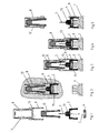
- Im folgenden wird die Erfindung an einem in der Zeichnung dargestellten Ausführungsbeispiel näher erläutert; es zeigen:
- Fig. 1
- die Kanülenkappe mit der Verschlußscheibe sowie dem Verschlußteil in der Art einer Explosionsdarstellung,
- Fig. 2
- den Gegenstand nach Fig. 1 in zum Aufsetzen auf die Spritze vorkonfektioniertem Zustand,
- Fig. 3
- den Gegenstand nach Fig. 2, jedoch im auf die Spritze aufgesetzten Zustand,
- Fig. 4
- den Gegenstand nach Fig. 3 im fertig konfektioniertem Zustand,
- Fig. 5
- den Gegenstand nach Fig. 4, jedoch vorbereitet für die Applikation.
- Die in der Zeichnung nur teilweise dargestellte Spritze oder Karpule ist vorgesehen für medizinische Zwecke und besteht aus einem Spritzenzylinder 1 aus Glas sowie einem in der Zeichnung nicht wiedergegebenen, im Spritzenzylinder 1 angeordneten Spritzenkolben, der mittels einer ebenfalls nicht dargestellten Kolbenstange verschiebbar ist. Diese Spritze ist dazu vorgesehen, im vorgefüllten Zustand und weitestgehend vorbereitet für eine unmittelbare Applikation in den Verkehr zu kommen.
- Am kanülenseitigen Ende des Spritzenzylinders 1 ist axial eine Kanülenkappe 2 aufgesetzt, die dort im Rastsitz gehalten ist. In die Kanülenkappe 2 ist eine Kanüle 3 fest eingesetzt.
- Ferner ist eine Verschlußscheibe 4 vorgesehen, die koaxial in der Kanülerikappe 2 angeordnet ist und einerseits stirnseitig dem Spritzenzylinder 1 und andererseits der innenseitigen Stirnfläche der Kanülenkappe 2 anliegt. Diese Verschlußscheibe 4 weist mittig eine Ausnehmung 5 in Form eines Sackloches auf, wobei der Boden dieser Ausnehmung 5 eine dünne Membran bildet.
- Das dem Spritzenzylinder 1 zugewandte Ende der Kanüle 3 steht frei über die innenseitige Stirnfläche der Kanülenkappe 2 in die Ausnehmung 5 der Verschlußscheibe 4 hinein vor, so dass unter dem Druck des Spritzenkolbens, der über die Flüssigkeit auf die Membran übertragen wird, diese sich zur innenseitigen Spitze 6 der Kanüle 3 hin verformt und dadurch durchstochen bzw. zerstört wird. Damit ist die Spritze für der Anwendung selbstaktivierend ausgebildet.
- Ferner ist ein die Kanüle 3 schützendes Verschlußteil 7 vorgesehen, dass aus einer Verschlußkappe 8 sowie einem Klemmring 9 besteht, wobei die Verschlußkappe 8 mit dem Klemmring 9 über eine Sollbruchstelle 10 verbunden ist. Diese Sollbruchstelle 10 ermöglicht es, die Verschlußkappe 8 vor der Anwendung der Spritze auf einfache Weise abzutrennen.
- An der Außenmantelfläche der Kanülenkappe 2 ist für den Klemmring 9 eine erste Rastposition 11 vorgesehen, bei der eine Verbindung des Innenraums des Verschlußteils 7 mit der Umgebung besteht, so dass dieser Innenraum sterilisiert werden kann. Diese erste Rastposition 11 ergibt sich aus den Figuren 2 und 3. Nach erfolgter Sterilisierung kann das Verschlußteil 7 - noch unter sterilen Bedingungen - durch einfaches Aufdrücken in die in Figur 4 dargestellte zweite Rastposition verstellt werden, in der dann eine sterile Abdichtung gegenüber der Kanülenkappe 2 gegeben ist.
- Zusätzlich ist im Inneren des Verschlußteils 7 eine aus Gummi bestehende Nadelschutzkappe 12 angeordnet.
- Die Kanülenkappe 2 weist einen zylindrischen, die Kanüle 3 umschließenden Vorsprung 13 auf, der in der zweiten Rastposition des Verschlußteils 7 dichtend der Innenmantelfläche der Nadelschutzkappe 12 anliegt.
- Durch diese Anordnung ist es möglich, auf einfach Weise eine Spritze bereitzustellen, zu deren Applikation lediglich die Verschlußkappe 8 abgetrennt werden muss. Insbesondere ist die Spritze bereits mit der Kanüle 3 versehen, ohne dass Einschränkungen im Prozessablauf in Kauf genommen werden müßten. Der Spritzenzylinder 1 kann also insbesondere Hochtemperaturprozessen, wie z. B. einer Einbrennsilikonisierung, unterworfen werden, ohne dass hierdurch der Sitz bzw. Halt der Kanüle beeinflusst wird. Darüber hinaus erlaubt die Anordnung eine blasenfreie Füllung des Spritzenzylinders 1 mit der pharmazeutischen Substanz.
Claims (6)
- Vorgefüllte Spritze oder Karpule für medizinische Zwecke, mit einem Spritzenzylinder (1) aus Glas und einem darin angeordneten, mittels einer Kolbenstange verschiebbaren Spritzenkolben, ferner mit einer am kanülenseitigen Ende des Spritzenzylinders (1) axial aufgesetzten, im Rastsitz gehaltenen Kanülenkappe (2), in die eine Kanüle (3) fest eingesetzt ist, ferner mit einer zur Kanülenkappe (2) koaxial angeordneten, in die Kanülenkappe (2) eingesetzten Verschlußscheibe (4), die einerseits stirnseitig dem Spritzenzylinder (1) und andererseits der innenseitigen Stirnfläche der Kanülenkappe (2) anliegt und mittig eine Ausnehmung (5) in Form eines Sacklochs aufweist, deren Boden eine Membran bildet, wobei das dem Spritzenzylinder (1) zugewandte Ende der Kanüle (3) über die innenseitige Stirnfläche der Kanülenkappe (2) frei in die Ausnehmung (5) der Verschlußscheibe (4) vorsteht, sowie mit einem aus einer Verschlußkappe (8) und einem daran über eine Sollbruchstelle (10) angeschlossenen Klemmring (9) bestehenden Verschlußteil (7), das von einer ersten, an der Außenmantelfläche der Kanülenkappe (2) für den Klemmring (9) ausgebildeten Rastposition (11), die eine Sterilisierung des Verschlußteilinnenraums ermöglicht, in eine zweite, die Kanülenkappe (2) steril abdichtend umschließende Rastposition verstellbar ist.
- Spritze oder Karpule nach Anspruch 1, dadurch gekennzeichnet, daß im Inneren des Verschlußteils (7) eine Nadelschutzkappe (12) angeordnet ist.
- Spritze oder Karpule nach Anspruch 2, dadurch gekennzeichnet, daß die Nadelschutzkappe (12) aus Gummi besteht.
- Spritze oder Karpule nach Anspruch 2 oder 3, dadurch gekennzeichnet, daß die Kanülenkappe (2) einen zylindrischen, die Kanüle (3) umschließenden Vorsprung (13) aufweist, der in der zweiten Rastposition des Verschlußteils (7) dichtend der Innenmantelfläche der Nadelschutzkappe (12) anliegt.
- Verfahren zur Konfektionierung einer Spritze oder Karpule nach den Ansprüchen 1 bis 4, dadurch gekennzeichnet, daß nach dem Reinigen des aus Glas bestehenden Spritzenzylinders (1) eine Einbrennsilikonisierung erfolgt, daß anschließend die Befüllung des Spritzenzylinders (1) erfolgt, daß sodann die Kanülenkappe (2) mit darin angeordneter Verschlußscheibe (4) und in der ersten Rastposition (11) aufgesetztem Verschlußteil (7) auf den Spritzenzylinder (1) aufgeprellt und danach die Spritze oder Karpule sterilisiert wird und schließlich das Verschlußteil (7) in die zweite Rastposition niedergedrückt wird.
- Verfahren nach Anspruch 5, dadurch gekennzeichnet, daß der Spritzenzylinder (1) blasenfrei befüllt wird.
Priority Applications (2)
| Application Number | Priority Date | Filing Date | Title |
|---|---|---|---|
| SI200330924T SI1466638T1 (sl) | 2003-04-09 | 2003-12-13 | Predhodno napolnjena brizgalka ali karpula za medicinske namene |
| CY20071101191T CY1106869T1 (el) | 2003-04-09 | 2007-09-14 | Προπληρωμενη συριγγα ή μηχανισμος για ιατρικους σκοπους |
Applications Claiming Priority (2)
| Application Number | Priority Date | Filing Date | Title |
|---|---|---|---|
| DE10316127 | 2003-04-09 | ||
| DE10316127A DE10316127A1 (de) | 2003-04-09 | 2003-04-09 | Vorgefüllte Spritze oder Karpule für medizinische Zwecke |
Publications (3)
| Publication Number | Publication Date |
|---|---|
| EP1466638A2 EP1466638A2 (de) | 2004-10-13 |
| EP1466638A3 EP1466638A3 (de) | 2006-05-24 |
| EP1466638B1 true EP1466638B1 (de) | 2007-07-11 |
Family
ID=32864392
Family Applications (1)
| Application Number | Title | Priority Date | Filing Date |
|---|---|---|---|
| EP03028771A Expired - Lifetime EP1466638B1 (de) | 2003-04-09 | 2003-12-13 | Vorgefüllte Spritze oder Karpule für medizinische Zwecke |
Country Status (11)
| Country | Link |
|---|---|
| US (1) | US7331941B2 (de) |
| EP (1) | EP1466638B1 (de) |
| JP (1) | JP4347718B2 (de) |
| AT (1) | ATE366596T1 (de) |
| CA (1) | CA2457186C (de) |
| CY (1) | CY1106869T1 (de) |
| DE (2) | DE10316127A1 (de) |
| DK (1) | DK1466638T3 (de) |
| ES (1) | ES2289232T3 (de) |
| PT (1) | PT1466638E (de) |
| SI (1) | SI1466638T1 (de) |
Families Citing this family (37)
| Publication number | Priority date | Publication date | Assignee | Title |
|---|---|---|---|---|
| EP1502616A1 (de) * | 2003-08-01 | 2005-02-02 | Bünder Glas GmbH | Nadelschutz für eine Glasspritze |
| EP1754048A1 (de) * | 2003-12-08 | 2007-02-21 | Sentronic GmbH Gesellschaft für Optische Messsysteme | Sensitives system zur optischen detektion chemischer und/oder physikalischer zustandsänderungen innerhalb von verpackten medien |
| US7731678B2 (en) | 2004-10-13 | 2010-06-08 | Hyprotek, Inc. | Syringe devices and methods for mixing and administering medication |
| CA2626864C (en) | 2005-11-09 | 2015-06-02 | Hyprotek, Inc. | Syringe devices, components of syringe devices, and methods of forming components and syringe devices |
| DE102005058133A1 (de) * | 2005-11-30 | 2007-05-31 | Schott Ag | Spritze mit Verschluss |
| CN100493649C (zh) * | 2006-01-06 | 2009-06-03 | 威海洁瑞医用制品有限公司 | 静脉留置针止血密封塞及其生产方法 |
| GB0600351D0 (en) * | 2006-01-10 | 2006-02-15 | Weston Terence E | Safe hypodermic needle |
| WO2008077484A1 (de) * | 2006-12-21 | 2008-07-03 | Arzneimittel Gmbh Apotheker Vetter & Co. Ravensburg | Aufsatz für eine spritze und/oder eine karpule sowie verfahren zu dessen herstellung |
| DK2125084T3 (da) | 2006-12-22 | 2011-05-16 | Novo Nordisk As | Afskærmelig nåleanordning med forspændt sikkerhedsskærm |
| EP2203204B1 (de) * | 2007-09-25 | 2014-12-31 | Becton Dickinson France | Automatisches injektionsgerät |
| ES2742504T3 (es) * | 2007-09-25 | 2020-02-14 | Becton Dickinson France | Autoinyector con elemento de eliminación de blindaje que comprende medios antimanipulación |
| US9522097B2 (en) | 2007-10-04 | 2016-12-20 | Hyprotek, Inc. | Mixing/administration syringe devices, protective packaging and methods of protecting syringe handlers |
| US8002737B2 (en) | 2007-10-04 | 2011-08-23 | Hyprotek, Inc. | Mixing/administration syringe devices, protective packaging and methods of protecting syringe handlers |
| DE102009008754A1 (de) * | 2009-02-12 | 2010-08-26 | Tecpharma Licensing Ag | Verabreichungsvorrichtung, insbesondere Autoinjektionsvorrichtung, für eine medizinische Substanz mit einer Abzugshilfe für eine Schutzkappe |
| JP5653943B2 (ja) * | 2009-03-03 | 2015-01-14 | ノボ・ノルデイスク・エー/エス | キャップのロック装置 |
| JP5865835B2 (ja) * | 2009-08-12 | 2016-02-17 | サノフィ−アベンティス・ドイチュラント・ゲゼルシャフト・ミット・ベシュレンクテル・ハフツング | 携帯用医薬品送達デバイス用キャップ及びそのような医薬品送達デバイス |
| WO2012110057A1 (en) | 2011-02-15 | 2012-08-23 | Chemisches Institut Schaefer Ag | Cefuroxime safety kit |
| CN102068735A (zh) * | 2011-02-25 | 2011-05-25 | 山东威高集团医用高分子制品股份有限公司 | 一种预灌封玻璃注射器 |
| US8672883B2 (en) | 2011-07-11 | 2014-03-18 | C. Garyen Denning | Fluid delivery device and methods |
| WO2013089616A1 (en) * | 2011-12-15 | 2013-06-20 | Shl Group Ab | Cap assembly |
| WO2013153045A1 (en) * | 2012-04-10 | 2013-10-17 | Carebay Europe Ltd | Cap assembly |
| US8870028B2 (en) | 2012-05-25 | 2014-10-28 | Restek Corporation | Dispensing device |
| JP6273087B2 (ja) * | 2012-10-25 | 2018-01-31 | 大成化工株式会社 | シリンジ |
| FR3002739B1 (fr) * | 2013-03-01 | 2016-01-08 | Transformation Des Elastomeres A Usages Medicaux Et Ind Soc D | Dispositif de protection d'aiguille. |
| FR3002741B1 (fr) * | 2013-03-01 | 2016-01-08 | Transformation Des Elastomeres A Usages Medicaux Et Ind Soc D | Dispositif de protection d'aiguille. |
| FR3002738B1 (fr) | 2013-03-01 | 2020-11-20 | Societe De Transf Des Elastomeres A Usages Medicaux Et Industriels | Dispositif de protection d'aiguille. |
| CN103203052A (zh) * | 2013-04-03 | 2013-07-17 | 山东威高集团医用高分子制品股份有限公司 | 一种安全型预充式冲管注射器 |
| WO2016102299A1 (en) * | 2014-12-22 | 2016-06-30 | Novo Nordisk A/S | An injection device with a removable cap |
| EP3275485A4 (de) * | 2015-03-26 | 2018-06-27 | Terumo Kabushiki Kaisha | Spritzenkappe, spritzenanordnung und vorgefüllte spritze |
| FR3041334B1 (fr) * | 2015-09-21 | 2020-02-14 | Disposable-Lab | Procede d'obturation d'un contenant comportant au moins un bouchon, notamment une carpule, moyens d'insertion et ligne d'obturation associee |
| EP3173113A1 (de) | 2015-11-27 | 2017-05-31 | Sanofi-Aventis Deutschland GmbH | Injektionsnadelanordnung |
| JP6924756B2 (ja) | 2015-11-27 | 2021-08-25 | サノフィ−アベンティス・ドイチュラント・ゲゼルシャフト・ミット・ベシュレンクテル・ハフツング | キャップをもつ薬物送達デバイス |
| DK3380146T3 (da) * | 2015-11-27 | 2022-11-07 | Sanofi Aventis Deutschland | Medikamentadministrationsanordning |
| WO2019053111A1 (en) * | 2017-09-14 | 2019-03-21 | Becton Dickinson France | SAFETY ASSEMBLY AND MEDICAL DEVICE WITH SAFETY ASSEMBLY |
| EP3681569B1 (de) * | 2017-09-14 | 2022-03-16 | Becton Dickinson France | Sicherungsanordnung |
| EP3466467B1 (de) * | 2017-10-06 | 2022-04-27 | SHL Medical AG | Nadelschutzvorrichtung |
| US20220184322A1 (en) * | 2019-04-26 | 2022-06-16 | Becton Dickinson France | Needle cover with undercut |
Family Cites Families (11)
| Publication number | Priority date | Publication date | Assignee | Title |
|---|---|---|---|---|
| CH75287A (de) * | 1916-10-31 | 1917-11-16 | Auxiliaire De Brevets Soc | Spritze für hypodermische Injektionen |
| DE847473C (de) * | 1944-04-07 | 1952-08-25 | Albert Heinrich Dr Med Bertram | Ampullenspritze |
| DE58908082D1 (de) * | 1989-05-17 | 1994-08-25 | Vetter & Co Apotheker | Spritze für medizinische Zwecke. |
| DE4127650C1 (de) * | 1991-08-21 | 1993-02-25 | Arzneimittel Gmbh Apotheker Vetter & Co Ravensburg, 7980 Ravensburg, De | |
| US5447500A (en) * | 1993-09-29 | 1995-09-05 | Sterling Winthrop, Inc. | Collar and cartridge-needle unit assembly |
| JP3383966B2 (ja) * | 1994-05-27 | 2003-03-10 | ニプロ株式会社 | プレフィルドシリンジ |
| US5879337A (en) * | 1997-02-27 | 1999-03-09 | Injectimed, Inc. | Needle tip guard for hypodermic needles |
| AT404430B (de) * | 1996-06-25 | 1998-11-25 | Med Plastic Ag | Injektionsspritzenkopf mit originalitätsverschluss |
| DE19638940C2 (de) * | 1996-09-23 | 1999-01-07 | Vetter & Co Apotheker | Vorgefüllte Spritze für medizinische Zwecke |
| DE19751219A1 (de) * | 1997-11-19 | 1999-05-27 | Vetter & Co Apotheker | Spritze, insbesondere vorgefüllte Spritze, oder Karpule |
| FR2799376B1 (fr) * | 1999-10-07 | 2002-01-18 | Marc Brunel | Dispositif d'injection a usage unique |
-
2003
- 2003-04-09 DE DE10316127A patent/DE10316127A1/de not_active Withdrawn
- 2003-12-13 DE DE50307650T patent/DE50307650D1/de not_active Expired - Lifetime
- 2003-12-13 EP EP03028771A patent/EP1466638B1/de not_active Expired - Lifetime
- 2003-12-13 PT PT03028771T patent/PT1466638E/pt unknown
- 2003-12-13 ES ES03028771T patent/ES2289232T3/es not_active Expired - Lifetime
- 2003-12-13 SI SI200330924T patent/SI1466638T1/sl unknown
- 2003-12-13 AT AT03028771T patent/ATE366596T1/de active
- 2003-12-13 DK DK03028771T patent/DK1466638T3/da active
-
2004
- 2004-02-10 CA CA002457186A patent/CA2457186C/en not_active Expired - Lifetime
- 2004-02-23 JP JP2004046533A patent/JP4347718B2/ja not_active Expired - Lifetime
- 2004-04-08 US US10/821,253 patent/US7331941B2/en active Active
-
2007
- 2007-09-14 CY CY20071101191T patent/CY1106869T1/el unknown
Also Published As
| Publication number | Publication date |
|---|---|
| US7331941B2 (en) | 2008-02-19 |
| DE10316127A1 (de) | 2004-11-04 |
| US20050027259A1 (en) | 2005-02-03 |
| PT1466638E (pt) | 2007-09-05 |
| DE50307650D1 (de) | 2007-08-23 |
| ATE366596T1 (de) | 2007-08-15 |
| DK1466638T3 (da) | 2007-10-22 |
| CA2457186C (en) | 2007-03-13 |
| ES2289232T3 (es) | 2008-02-01 |
| JP4347718B2 (ja) | 2009-10-21 |
| CA2457186A1 (en) | 2004-10-09 |
| SI1466638T1 (sl) | 2007-10-31 |
| EP1466638A2 (de) | 2004-10-13 |
| EP1466638A3 (de) | 2006-05-24 |
| CY1106869T1 (el) | 2012-09-26 |
| JP2004305720A (ja) | 2004-11-04 |
Similar Documents
| Publication | Publication Date | Title |
|---|---|---|
| EP1466638B1 (de) | Vorgefüllte Spritze oder Karpule für medizinische Zwecke | |
| DE19638940C2 (de) | Vorgefüllte Spritze für medizinische Zwecke | |
| DE69533027T2 (de) | Spritze mit flanschadapter | |
| DE69816965T2 (de) | Verriegelbare schutzschildanordnung für eine vorfüllbare spritze | |
| EP1804862B1 (de) | Verfahren und vorrichtungen zum lyophilisieren, rekonstituieren und verabreichen eines rekonstituierten wirkstoffes | |
| DE60102517T2 (de) | Hypodermische Spritze mit selektiv zurückziehbarer Nadel | |
| DE60028423T2 (de) | Spritze mit zurückziehbarer Nadel | |
| EP0917882B1 (de) | Spritze, insbesondere vorgefüllte Spritze oder Karpule | |
| EP0609741B1 (de) | Vorgefüllte Spritze | |
| DE60024202T2 (de) | Herstellungsmethode einer Spritze mit einziehbarer Nadel | |
| DE3916101A1 (de) | Spritze fuer medizinische zwecke | |
| EP1186312B1 (de) | Austragsvorrichtung für Medien | |
| EP1658107B1 (de) | Vorrichtung zur injektion eines injizierbaren produktes | |
| DE202013012825U1 (de) | Spritze | |
| WO2004047895A1 (de) | Vorrichtung zur sicherung von injektionsnadeln | |
| EP2720739B1 (de) | Transport- und transferbehältnis für ein fluides medium | |
| DE10121232C2 (de) | Vorrichtung zum Verabreichen von Medikamenten | |
| EP3750580A1 (de) | Mit einem fluid vorfüllbarer oder vorgefüllter behälter sowie kanülenbaugruppe und verschlusssystem für einen mit einem fluid vorfüllbaren oder vorgefüllten behälter | |
| WO2010075929A1 (de) | Injektor mit zylinder-kolben-einheit und dauerhaft sterilem aktiven kolbenhemd | |
| WO2009092430A1 (de) | Spritzensystem und verfahren zu dessen herstellung | |
| WO2009089638A1 (de) | Nadeleinheit mit einer zwischen nadelträger und nadelverpackungshülse angeordneten hülse | |
| WO2020249738A2 (de) | Flüssigkeitstransfersystem und komponenten dafür | |
| EP1962928A1 (de) | System zur injektion durch oder in die menschliche haut | |
| DE102008005938A1 (de) | Vorgefüllte Spritze und Verfahren zum Verpacken einer Spritze | |
| EP0935476A1 (de) | Spritze mit spritzenstopfen aus polyethylen |
Legal Events
| Date | Code | Title | Description |
|---|---|---|---|
| PUAI | Public reference made under article 153(3) epc to a published international application that has entered the european phase |
Free format text: ORIGINAL CODE: 0009012 |
|
| AK | Designated contracting states |
Kind code of ref document: A2 Designated state(s): AT BE BG CH CY CZ DE DK EE ES FI FR GB GR HU IE IT LI LU MC NL PT RO SE SI SK TR |
|
| AX | Request for extension of the european patent |
Extension state: AL LT LV MK |
|
| RIC1 | Information provided on ipc code assigned before grant |
Ipc: A61M 5/00 19680901ALI20051112BHEP Ipc: A61M 5/32 19680901ALI20051112BHEP Ipc: A61M 5/50 19900101ALI20051112BHEP Ipc: A61M 5/34 19740701ALI20051112BHEP Ipc: A61M 5/28 19680901AFI20040816BHEP |
|
| 17P | Request for examination filed |
Effective date: 20051224 |
|
| PUAL | Search report despatched |
Free format text: ORIGINAL CODE: 0009013 |
|
| AK | Designated contracting states |
Kind code of ref document: A3 Designated state(s): AT BE BG CH CY CZ DE DK EE ES FI FR GB GR HU IE IT LI LU MC NL PT RO SE SI SK TR |
|
| AX | Request for extension of the european patent |
Extension state: AL LT LV MK |
|
| GRAP | Despatch of communication of intention to grant a patent |
Free format text: ORIGINAL CODE: EPIDOSNIGR1 |
|
| AKX | Designation fees paid |
Designated state(s): AT BE BG CH CY CZ DE DK EE ES FI FR GB GR HU IE IT LI LU MC NL PT RO SE SI SK TR |
|
| GRAS | Grant fee paid |
Free format text: ORIGINAL CODE: EPIDOSNIGR3 |
|
| GRAA | (expected) grant |
Free format text: ORIGINAL CODE: 0009210 |
|
| AK | Designated contracting states |
Kind code of ref document: B1 Designated state(s): AT BE BG CH CY CZ DE DK EE ES FI FR GB GR HU IE IT LI LU MC NL PT RO SE SI SK TR |
|
| REG | Reference to a national code |
Ref country code: GB Ref legal event code: FG4D Free format text: NOT ENGLISH |
|
| REG | Reference to a national code |
Ref country code: CH Ref legal event code: NV Representative=s name: ISLER & PEDRAZZINI AG Ref country code: CH Ref legal event code: EP |
|
| REF | Corresponds to: |
Ref document number: 50307650 Country of ref document: DE Date of ref document: 20070823 Kind code of ref document: P |
|
| REG | Reference to a national code |
Ref country code: PT Ref legal event code: SC4A Free format text: AVAILABILITY OF NATIONAL TRANSLATION Effective date: 20070824 Ref country code: IE Ref legal event code: FG4D Free format text: LANGUAGE OF EP DOCUMENT: GERMAN |
|
| GBT | Gb: translation of ep patent filed (gb section 77(6)(a)/1977) |
Effective date: 20070906 |
|
| REG | Reference to a national code |
Ref country code: CH Ref legal event code: PCAR Free format text: ISLER & PEDRAZZINI AG;POSTFACH 1772;8027 ZUERICH (CH) |
|
| REG | Reference to a national code |
Ref country code: GR Ref legal event code: EP Ref document number: 20070402472 Country of ref document: GR |
|
| REG | Reference to a national code |
Ref country code: RO Ref legal event code: EPE |
|
| REG | Reference to a national code |
Ref country code: SE Ref legal event code: TRGR |
|
| REG | Reference to a national code |
Ref country code: DK Ref legal event code: T3 |
|
| ET | Fr: translation filed | ||
| REG | Reference to a national code |
Ref country code: EE Ref legal event code: FG4A Ref document number: E001467 Country of ref document: EE Effective date: 20070921 |
|
| REG | Reference to a national code |
Ref country code: HU Ref legal event code: AG4A Ref document number: E002279 Country of ref document: HU |
|
| REG | Reference to a national code |
Ref country code: ES Ref legal event code: FG2A Ref document number: 2289232 Country of ref document: ES Kind code of ref document: T3 |
|
| PLBE | No opposition filed within time limit |
Free format text: ORIGINAL CODE: 0009261 |
|
| STAA | Information on the status of an ep patent application or granted ep patent |
Free format text: STATUS: NO OPPOSITION FILED WITHIN TIME LIMIT |
|
| 26N | No opposition filed |
Effective date: 20080414 |
|
| PGFP | Annual fee paid to national office [announced via postgrant information from national office to epo] |
Ref country code: CZ Payment date: 20100708 Year of fee payment: 8 Ref country code: EE Payment date: 20100830 Year of fee payment: 8 Ref country code: SK Payment date: 20100913 Year of fee payment: 8 Ref country code: TR Payment date: 20100906 Year of fee payment: 8 |
|
| PGFP | Annual fee paid to national office [announced via postgrant information from national office to epo] |
Ref country code: DK Payment date: 20101209 Year of fee payment: 8 Ref country code: MC Payment date: 20101220 Year of fee payment: 8 |
|
| PGFP | Annual fee paid to national office [announced via postgrant information from national office to epo] |
Ref country code: BG Payment date: 20101216 Year of fee payment: 8 Ref country code: FI Payment date: 20101220 Year of fee payment: 8 Ref country code: HU Payment date: 20101026 Year of fee payment: 8 Ref country code: LU Payment date: 20101202 Year of fee payment: 8 Ref country code: RO Payment date: 20101210 Year of fee payment: 8 Ref country code: SI Payment date: 20100906 Year of fee payment: 8 |
|
| PGFP | Annual fee paid to national office [announced via postgrant information from national office to epo] |
Ref country code: CY Payment date: 20101013 Year of fee payment: 8 |
|
| REG | Reference to a national code |
Ref country code: DK Ref legal event code: EBP |
|
| PG25 | Lapsed in a contracting state [announced via postgrant information from national office to epo] |
Ref country code: MC Free format text: LAPSE BECAUSE OF NON-PAYMENT OF DUE FEES Effective date: 20111231 Ref country code: CZ Free format text: LAPSE BECAUSE OF NON-PAYMENT OF DUE FEES Effective date: 20111213 |
|
| REG | Reference to a national code |
Ref country code: EE Ref legal event code: MM4A Ref document number: E001467 Country of ref document: EE Effective date: 20111231 |
|
| PG25 | Lapsed in a contracting state [announced via postgrant information from national office to epo] |
Ref country code: FI Free format text: LAPSE BECAUSE OF NON-PAYMENT OF DUE FEES Effective date: 20111213 |
|
| REG | Reference to a national code |
Ref country code: SI Ref legal event code: KO00 Effective date: 20120730 |
|
| REG | Reference to a national code |
Ref country code: SK Ref legal event code: MM4A Ref document number: E 2432 Country of ref document: SK Effective date: 20111213 |
|
| PG25 | Lapsed in a contracting state [announced via postgrant information from national office to epo] |
Ref country code: CY Free format text: LAPSE BECAUSE OF NON-PAYMENT OF DUE FEES Effective date: 20111213 |
|
| PG25 | Lapsed in a contracting state [announced via postgrant information from national office to epo] |
Ref country code: RO Free format text: LAPSE BECAUSE OF NON-PAYMENT OF DUE FEES Effective date: 20111213 Ref country code: EE Free format text: LAPSE BECAUSE OF NON-PAYMENT OF DUE FEES Effective date: 20111231 |
|
| PG25 | Lapsed in a contracting state [announced via postgrant information from national office to epo] |
Ref country code: SK Free format text: LAPSE BECAUSE OF NON-PAYMENT OF DUE FEES Effective date: 20111213 Ref country code: HU Free format text: LAPSE BECAUSE OF NON-PAYMENT OF DUE FEES Effective date: 20111214 Ref country code: SI Free format text: LAPSE BECAUSE OF NON-PAYMENT OF DUE FEES Effective date: 20111214 |
|
| PG25 | Lapsed in a contracting state [announced via postgrant information from national office to epo] |
Ref country code: DK Free format text: LAPSE BECAUSE OF NON-PAYMENT OF DUE FEES Effective date: 20120102 |
|
| PG25 | Lapsed in a contracting state [announced via postgrant information from national office to epo] |
Ref country code: LU Free format text: LAPSE BECAUSE OF NON-PAYMENT OF DUE FEES Effective date: 20111213 |
|
| PG25 | Lapsed in a contracting state [announced via postgrant information from national office to epo] |
Ref country code: BG Free format text: LAPSE BECAUSE OF NON-PAYMENT OF DUE FEES Effective date: 20121231 |
|
| PG25 | Lapsed in a contracting state [announced via postgrant information from national office to epo] |
Ref country code: TR Free format text: LAPSE BECAUSE OF NON-PAYMENT OF DUE FEES Effective date: 20111213 |
|
| REG | Reference to a national code |
Ref country code: FR Ref legal event code: PLFP Year of fee payment: 14 |
|
| REG | Reference to a national code |
Ref country code: FR Ref legal event code: PLFP Year of fee payment: 15 |
|
| REG | Reference to a national code |
Ref country code: DE Ref legal event code: R082 Ref document number: 50307650 Country of ref document: DE Representative=s name: BAUR & WEBER PATENTANWAELTE PARTG MBB, DE |
|
| PGFP | Annual fee paid to national office [announced via postgrant information from national office to epo] |
Ref country code: SE Payment date: 20221223 Year of fee payment: 20 Ref country code: PT Payment date: 20221129 Year of fee payment: 20 Ref country code: NL Payment date: 20221226 Year of fee payment: 20 Ref country code: IE Payment date: 20221221 Year of fee payment: 20 Ref country code: GB Payment date: 20221220 Year of fee payment: 20 Ref country code: FR Payment date: 20221222 Year of fee payment: 20 Ref country code: AT Payment date: 20221221 Year of fee payment: 20 |
|
| PGFP | Annual fee paid to national office [announced via postgrant information from national office to epo] |
Ref country code: GR Payment date: 20221223 Year of fee payment: 20 Ref country code: BE Payment date: 20221226 Year of fee payment: 20 |
|
| PGFP | Annual fee paid to national office [announced via postgrant information from national office to epo] |
Ref country code: ES Payment date: 20230118 Year of fee payment: 20 Ref country code: CH Payment date: 20221228 Year of fee payment: 20 |
|
| PGFP | Annual fee paid to national office [announced via postgrant information from national office to epo] |
Ref country code: IT Payment date: 20221222 Year of fee payment: 20 Ref country code: DE Payment date: 20221227 Year of fee payment: 20 |
|
| REG | Reference to a national code |
Ref country code: DE Ref legal event code: R071 Ref document number: 50307650 Country of ref document: DE Ref country code: NL Ref legal event code: MK Effective date: 20231212 |
|
| REG | Reference to a national code |
Ref country code: CH Ref legal event code: PL |
|
| REG | Reference to a national code |
Ref country code: ES Ref legal event code: FD2A Effective date: 20231228 |
|
| REG | Reference to a national code |
Ref country code: GB Ref legal event code: PE20 Expiry date: 20231212 |
|
| REG | Reference to a national code |
Ref country code: BE Ref legal event code: MK Effective date: 20231213 |
|
| PG25 | Lapsed in a contracting state [announced via postgrant information from national office to epo] |
Ref country code: GB Free format text: LAPSE BECAUSE OF EXPIRATION OF PROTECTION Effective date: 20231212 |
|
| PG25 | Lapsed in a contracting state [announced via postgrant information from national office to epo] |
Ref country code: ES Free format text: LAPSE BECAUSE OF EXPIRATION OF PROTECTION Effective date: 20231214 |
|
| REG | Reference to a national code |
Ref country code: SE Ref legal event code: EUG |
|
| PG25 | Lapsed in a contracting state [announced via postgrant information from national office to epo] |
Ref country code: PT Free format text: LAPSE BECAUSE OF EXPIRATION OF PROTECTION Effective date: 20231226 Ref country code: GB Free format text: LAPSE BECAUSE OF EXPIRATION OF PROTECTION Effective date: 20231212 Ref country code: ES Free format text: LAPSE BECAUSE OF EXPIRATION OF PROTECTION Effective date: 20231214 |
|
| REG | Reference to a national code |
Ref country code: IE Ref legal event code: MK9A |
|
| REG | Reference to a national code |
Ref country code: AT Ref legal event code: MK07 Ref document number: 366596 Country of ref document: AT Kind code of ref document: T Effective date: 20231213 |
|
| PG25 | Lapsed in a contracting state [announced via postgrant information from national office to epo] |
Ref country code: IE Free format text: LAPSE BECAUSE OF EXPIRATION OF PROTECTION Effective date: 20231213 |
|
| PG25 | Lapsed in a contracting state [announced via postgrant information from national office to epo] |
Ref country code: IE Free format text: LAPSE BECAUSE OF EXPIRATION OF PROTECTION Effective date: 20231213 |