EP1466031B1 - Verfahren und vorrichtung zur verdichtung von substraten mittels chemischer gasphaseninfiltration - Google Patents
Verfahren und vorrichtung zur verdichtung von substraten mittels chemischer gasphaseninfiltration Download PDFInfo
- Publication number
- EP1466031B1 EP1466031B1 EP03712238A EP03712238A EP1466031B1 EP 1466031 B1 EP1466031 B1 EP 1466031B1 EP 03712238 A EP03712238 A EP 03712238A EP 03712238 A EP03712238 A EP 03712238A EP 1466031 B1 EP1466031 B1 EP 1466031B1
- Authority
- EP
- European Patent Office
- Prior art keywords
- enclosure
- duct
- reagent gas
- substrates
- installation
- Prior art date
- Legal status (The legal status is an assumption and is not a legal conclusion. Google has not performed a legal analysis and makes no representation as to the accuracy of the status listed.)
- Expired - Lifetime
Links
Images


Classifications
-
- C—CHEMISTRY; METALLURGY
- C23—COATING METALLIC MATERIAL; COATING MATERIAL WITH METALLIC MATERIAL; CHEMICAL SURFACE TREATMENT; DIFFUSION TREATMENT OF METALLIC MATERIAL; COATING BY VACUUM EVAPORATION, BY SPUTTERING, BY ION IMPLANTATION OR BY CHEMICAL VAPOUR DEPOSITION, IN GENERAL; INHIBITING CORROSION OF METALLIC MATERIAL OR INCRUSTATION IN GENERAL
- C23C—COATING METALLIC MATERIAL; COATING MATERIAL WITH METALLIC MATERIAL; SURFACE TREATMENT OF METALLIC MATERIAL BY DIFFUSION INTO THE SURFACE, BY CHEMICAL CONVERSION OR SUBSTITUTION; COATING BY VACUUM EVAPORATION, BY SPUTTERING, BY ION IMPLANTATION OR BY CHEMICAL VAPOUR DEPOSITION, IN GENERAL
- C23C16/00—Chemical coating by decomposition of gaseous compounds, without leaving reaction products of surface material in the coating, i.e. chemical vapour deposition [CVD] processes
- C23C16/04—Coating on selected surface areas, e.g. using masks
- C23C16/045—Coating cavities or hollow spaces, e.g. interior of tubes; Infiltration of porous substrates
-
- C—CHEMISTRY; METALLURGY
- C04—CEMENTS; CONCRETE; ARTIFICIAL STONE; CERAMICS; REFRACTORIES
- C04B—LIME, MAGNESIA; SLAG; CEMENTS; COMPOSITIONS THEREOF, e.g. MORTARS, CONCRETE OR LIKE BUILDING MATERIALS; ARTIFICIAL STONE; CERAMICS; REFRACTORIES; TREATMENT OF NATURAL STONE
- C04B35/00—Shaped ceramic products characterised by their composition; Ceramics compositions; Processing powders of inorganic compounds preparatory to the manufacturing of ceramic products
- C04B35/71—Ceramic products containing macroscopic reinforcing agents
- C04B35/78—Ceramic products containing macroscopic reinforcing agents containing non-metallic materials
- C04B35/80—Fibres, filaments, whiskers, platelets, or the like
- C04B35/83—Carbon fibres in a carbon matrix
-
- C—CHEMISTRY; METALLURGY
- C04—CEMENTS; CONCRETE; ARTIFICIAL STONE; CERAMICS; REFRACTORIES
- C04B—LIME, MAGNESIA; SLAG; CEMENTS; COMPOSITIONS THEREOF, e.g. MORTARS, CONCRETE OR LIKE BUILDING MATERIALS; ARTIFICIAL STONE; CERAMICS; REFRACTORIES; TREATMENT OF NATURAL STONE
- C04B41/00—After-treatment of mortars, concrete, artificial stone or ceramics; Treatment of natural stone
- C04B41/45—Coating or impregnating, e.g. injection in masonry, partial coating of green or fired ceramics, organic coating compositions for adhering together two concrete elements
-
- C—CHEMISTRY; METALLURGY
- C23—COATING METALLIC MATERIAL; COATING MATERIAL WITH METALLIC MATERIAL; CHEMICAL SURFACE TREATMENT; DIFFUSION TREATMENT OF METALLIC MATERIAL; COATING BY VACUUM EVAPORATION, BY SPUTTERING, BY ION IMPLANTATION OR BY CHEMICAL VAPOUR DEPOSITION, IN GENERAL; INHIBITING CORROSION OF METALLIC MATERIAL OR INCRUSTATION IN GENERAL
- C23C—COATING METALLIC MATERIAL; COATING MATERIAL WITH METALLIC MATERIAL; SURFACE TREATMENT OF METALLIC MATERIAL BY DIFFUSION INTO THE SURFACE, BY CHEMICAL CONVERSION OR SUBSTITUTION; COATING BY VACUUM EVAPORATION, BY SPUTTERING, BY ION IMPLANTATION OR BY CHEMICAL VAPOUR DEPOSITION, IN GENERAL
- C23C16/00—Chemical coating by decomposition of gaseous compounds, without leaving reaction products of surface material in the coating, i.e. chemical vapour deposition [CVD] processes
- C23C16/44—Chemical coating by decomposition of gaseous compounds, without leaving reaction products of surface material in the coating, i.e. chemical vapour deposition [CVD] processes characterised by the method of coating
- C23C16/455—Chemical coating by decomposition of gaseous compounds, without leaving reaction products of surface material in the coating, i.e. chemical vapour deposition [CVD] processes characterised by the method of coating characterised by the method used for introducing gases into reaction chamber or for modifying gas flows in reaction chamber
- C23C16/45563—Gas nozzles
- C23C16/45578—Elongated nozzles, tubes with holes
-
- Y—GENERAL TAGGING OF NEW TECHNOLOGICAL DEVELOPMENTS; GENERAL TAGGING OF CROSS-SECTIONAL TECHNOLOGIES SPANNING OVER SEVERAL SECTIONS OF THE IPC; TECHNICAL SUBJECTS COVERED BY FORMER USPC CROSS-REFERENCE ART COLLECTIONS [XRACs] AND DIGESTS
- Y10—TECHNICAL SUBJECTS COVERED BY FORMER USPC
- Y10S—TECHNICAL SUBJECTS COVERED BY FORMER USPC CROSS-REFERENCE ART COLLECTIONS [XRACs] AND DIGESTS
- Y10S427/00—Coating processes
- Y10S427/10—Chemical vapor infiltration, i.e. CVI
Definitions
- the invention relates to chemical vapor infiltration techniques.
- the field of application of the invention is the densification of porous substrates, in particular the production of composite material parts by densification of fibrous substrates by a matrix.
- a process for densifying substrates by chemical vapor infiltration comprises the steps of loading porous substrates to be densified in a charging zone of an enclosure, heating the internal volume of the enclosure, introduction of a reactive gas in the enclosure through an inlet located at one end thereof, and the preheating of the reactive gas after entering the chamber and before coming into contact with the parts located in the loading zone.
- the temperature and the pressure prevailing in the chamber are chosen to allow the reactive gas to diffuse within the porosity of the substrates and to deposit therein the material constituting the matrix by decomposition of one or more components of the reactive gas or by reaction between several components.
- the preheating of the reactive gas is usually carried out by passing the gas through a preheating zone located in the chamber and in which the reagent gas inlet opens.
- a conventional preheating zone comprises a plurality of perforated trays disposed one above the other and brought to the internal temperature of the enclosure.
- the preheating of the reactive gas is intended to bring it, as soon as it enters the loading zone, to a temperature as close as possible to that required for the formation of the desired matrix.
- the reaction temperature is typically of the order of 1000 ° C for the formation of pyrolytic carbon matrix or ceramic
- a reactive gas temperature of a few tens of ° C only to the desired temperature can affect significantly the densification kinetics and the microstructure of the deposited matrix material.
- the reactive gas reaching the top of the piles has traveled over their entire height and has matured, so that the substrates at the top of the piles receive a reactive gas whose composition may be different from that of the gas. reactive when entering the loading area. This can also result in different densification characteristics.
- the object of the invention is to provide a method for improving the distribution and preheating of the reactive gas and, in general, for reducing densification gradients between substrates at different locations in the loading zone. and this without affecting the loading capacity, or even increasing it.
- This object is achieved by means of a method as defined at the beginning of the description and in which the preheating of the reactive gas admitted into the enclosure is achieved at least in part by passing through a duct connected to the gas inlet, extending through the loading zone and brought to the internal temperature of the enclosure, and the preheated reactive gas is distributed in the loading zone through one or more openings formed in the side wall of the conduit, along the same.
- the conduit ensures both the preheating of the reactive gas and its distribution in the loading zone.
- the distribution of the reactive gas may be through one or more slots extending longitudinally through the sidewall of the conduit.
- the reactant gas may be dispensed into the enclosure through a plurality of bores formed in the sidewall of the conduit.
- the reactive gas circulates in the duct advantageously in contact with walls forming heat exchange surfaces and extending inside the duct.
- the reactive gas admitted into the chamber is advantageously preheated and distributed by passing through a duct extending vertically inside the chamber. battery.
- the distribution of the reactive gas is then preferably carried out only through openings formed in the side wall of the conduit.
- the invention also aims to provide an installation for implementing the method defined above.
- an installation comprising an enclosure inside which there is a substrate loading zone to be densified, a susceptor defining the enclosure and associated with means for heating the enclosure, a gas inlet reagent at one end of the enclosure, and means for preheating the reactive gas located in the enclosure, installation in which a conduit is connected to the reactant gas inlet in the enclosure and extends through the zone of loading, the conduit being provided along its length of lateral openings which open in the loading zone in order to distribute the reactive gas therein.
- the openings are in the form of at least one longitudinal slot.
- the wall of the tube may then be formed of a plurality of panels forming between them longitudinal spaces.
- the openings are in the form of bores distributed along the conduit.
- walls are disposed inside the conduit. These inner walls may be in the form of longitudinal panels leaving between them spaces.
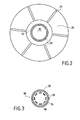
- the figure 1 shows schematically an enclosure 10 containing a loading of porous substrates 20.
- the substrates 20 are for example carbon fiber preforms or blanks formed of pre-densified preforms, which preforms or blanks are intended for the production of carbon / carbon composite (C / C) brake discs, by densification by a pyrolytic carbon matrix.
- C / C carbon / carbon composite
- the loading is in the form of a stack of substrates delimiting an internal volume 21 formed by the central passages of the vertically aligned substrates.
- the stack is carried by a lower support plate 11 supported by feet 12 a. It may be formed of several superimposed sections separated by one or more platters of intermediate supports 13.
- the plate 11 is provided with an opening 11a which is axially aligned with the central passages of the substrates 20 and 13 with apertures are intermediate plates 13.
- the stack of substrates is provided with a cover 22 closing the internal volume 21.
- the trays 13 are supported by the support plate 11 via columns or candles 12b .
- Each substrate 20 is separated from an adjacent substrate and, if appropriate, a plate 11 or 13 or the cover 22 by one or more spacers 23 which define intervals 24 ( figures 1 and 2 ).
- the shims 23, for example arranged radially, are arranged to form passages communicating the internal volume 21 with the external volume 25 located outside the stack in the enclosure.
- the passages formed by the shims 23 may be dimensioned so as to allow a balancing of the pressure between the volumes 21 and 25, as described in the document US 5,904,957 .
- it may be leakage passages with a restricted passage section so as to allow the existence of a pressure gradient between the volumes 21 and 25, as described in the patent application. FR 01 03 004 .
- the enclosure is heated by means of a susceptor 14 which delimits laterally the enclosure.
- the susceptor is for example an armature which is inductively coupled with an inductor 15.
- the inductor 15 surrounds the enclosure being separated from the armature 14 by a wall 16 forming a thermal insulator.
- the heating of the susceptor can be achieved by electrical resistors thermally coupled with the susceptor.
- a reactive gas containing one or more precursor components of carbon is introduced into the enclosure through a opening 17a formed in the bottom 17 of the enclosure.
- the precursors are gaseous hydrocarbon compounds, typically methane, propane, or a mixture of both.
- the reactive gas is channeled by a cylindrical wall 18 connecting the openings 17 a and 11 a.
- a vertical tubular conduit 30 is connected at its lower end to the opening 11a and extends vertically within the volume 21, to the immediate vicinity of the top of the stack of substrates. At its upper end, the conduit 30 is closed by a cover 31.
- the conduit 30 may be formed of several sections connected end to end allowing a modular construction.
- the duct 30 has its side wall 32 provided with a plurality of openings 33 in the form of bores which are distributed both along the length of the duct 30 and around the axis thereof.
- the reactive gas admitted into the chamber is distributed in the internal volume 21 by passing through the openings 33 of the conduit 30 and passes from the volume 21 to the volume 25 by diffusing through the substrates 20 and passing through the passages by the spacers 23.
- the residual gas is removed from the chamber 10 through an opening 19a which is formed in the cover 19 of the enclosure and which is connected to suction means (not shown).
- the duct 30 ensures not only the distribution of the reactive gas over the entire height of the cell, but also the preheating of this gas, the duct 30 being raised to the temperature prevailing in the chamber.
- internal heat exchange walls may be arranged inside the duct 30.
- these internal walls are in the form of longitudinal panels 35 distributed around the axis of the duct and leaving between them intervals 36.
- the conduit 30, the cover 31 and the possible internal walls 35 are for example graphite.
- Other materials are usable, for example a C / C composite material.
- the walls 14, 17, 19 of the enclosure 10 are advantageously made of graphite.
- the trays 11, 13, cover 22, spacers 23 and 18 are for example made of graphite or composite material C / C.
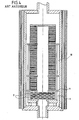
- the installation of figures 1 and 2 which is devoid of preheating zone, offers a substantially increased loading capacity.
- the loading zone of the enclosure 10, which extends above the plate 11, is larger than that of the installation of the figure 4 , the preheating zone with perforated trays 2 located one above the other, occupying a relatively large place.
- the conduit 30 should have a diameter sufficient to provide a large heat exchange surface, while remaining spaced apart from the stacked substrates.
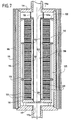
- FIGS. 5 and 6 illustrate an alternative embodiment of a duct 40 for preheating and distribution of reactive gas that can be substituted for the conduit 30 of the installation of figures 1 and 2 .
- the side wall 42 of the duct 40 has openings 43 in the form of longitudinal slots which extend along the length of the duct, the latter being closed by a cover 41 at its upper part.
- the slots 43 are rectilinear and regularly distributed around the axis of the duct 40.
- the slots 43 are formed by gaps between longitudinal panels 44 which constitute the side wall 42 of the duct 40. Additional internal walls of heat exchange are arranged in the duct 40. As in the embodiment of FIG. figure 3 these internal walls are in the form of longitudinal panels 45 distributed around the axis of the duct and leaving between them intervals 46. The panels 45 and 44 are staggered about the axis of the duct 40 so that an interval 46 opens onto a panel 44, between two slots 43.
- the slots may follow paths other than rectilinear, for example helical, between the bottom and top of the duct.
- all shapes can be given to the openings in the lateral wall of the duct, for example oblong shapes or elongate lumens extending axially, circumferentially or obliquely.
- a single stack of substrates 20 is shown.
- several stacks of substrates may be arranged side by side in the enclosure.
- a preheating and reactive gas distribution duct is disposed in each stack and is connected to a common inlet of reactive gas or, preferably, to a particular inlet aligned with the duct.
- the stack of annular substrates 120 is housed in an enclosure 110 delimited laterally by a susceptor 114 forming an armature inductively coupled with an inductor 115, with the interposition of an insulator 116.
- the stack of substrates 120 is formed of several superimposed sections separated by a or more intermediate trays 113 and rests on the lower plate 111 which has no central opening, to close the stack.
- the stack is topped by a cover 122 provided with a central opening 122 has axially aligned with the internal volume 121 of the stack.
- the reactive gas admitted is channeled by a cylindrical wall 118 which may optionally encompass a limited preheating zone gas.
- a vertical tubular conduit 130 is connected at its upper end to the opening 122 a and extends to plate 111 which closes the conduit at its lower end.
- the conduit 130 may be similar to the conduit 30 or conduit 40 described above.
- the duct 130 has the wall 132 provided with a plurality of openings 133 distributed along the length and around the axis of the duct.
- the reactive gas admitted into the chamber is distributed in the internal volume 121 of the stack of substrates by passing through the openings 133.
- the gas passes from the volume 121 to the volume 125 outside the stack diffusing through the substrates 120 and passing through passages formed by wedges interposed between the substrates.
- the residual gas is extracted from the enclosure through the central opening 117 of the bottom of the enclosure 117.
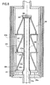
- the method and the installation according to the invention can be used for the densification of porous substrates other than brake disk preforms, for example for substrates constituting preforms 220 of divergent rocket motors, as shown by FIG. figure 8 .
- substrates 220 are arranged in the same loading zone of an enclosure 210 with their axial passages aligned vertically.
- the substrate bottom is carried by a plate 211 which rests on feet 212, while other substrates are based on annular intermediate plates 213.
- the plates 213 are supported by the support plate 211 by columns or candles 212b.
- the internal volumes of the substrates 220 form, with the central openings 213 of the plates 213, the internal volume 221 of the stack of substrates.
- the volume 221 is closed by a cover 222 at its upper part.
- Shims 223 are interposed between the axial ends of the substrates 220 and the plates 211, 213 and can thus provide passages communicating the volume 221 with the volume 225 outside the substrates in the enclosure.
- a conduit 230 for preheating and reactive gas distribution is connected at a lower end to a central opening 211a of the plate 211.
- the conduit 230 extends vertically in the volume 221 to the immediate vicinity of the top of the stack of substrates, where the conduit 230 is closed by a lid 231.
- the duct 230 has its side wall 232 provided with openings 233, for example in the form of bores, the duct 230 being of the same type as that of the embodiment of the invention. figures 1 and 2 .
- the field of application of the invention is not limited to the densification of annular or hollow axisymmetric substrates.
- the figure 9 shows an enclosure 310 with a lower support plate 311 and a plurality of intermediate support plates 313 in a chamber the loading zone 310.
- the plates 311 and 313 are provided with central openings 311a and 313 respectively has aligned with an input of reactive gas in the enclosure.
- a vertical preheating and reactant gas distribution conduit is connected at its lower part to the opening 311 a and extends vertically through the enclosure loading zone 310 passing through the apertures 313 a. At its upper end located near the top of the loading zone, the conduit 330 is closed by a cover 331.
- the plates 311 and 313 are supported by legs 312 and columns 312 b.
- the trays 311, 313 support substrates to be densified 320 (not all shown) which may be of various shapes and sizes.
- the method and the installation according to the invention can be implemented for the densification of porous substrates by matrices other than pyrolytic carbon, for example ceramic matrices.
- matrices other than pyrolytic carbon
- ceramic matrices for example ceramic matrices.
- Chemical vapor infiltration processes of ceramic materials, for example silicon carbide (SiC) are well known.
- the composition of the reactive gas is selected according to the nature of the matrix to be deposited.
- the passage section provided by the openings through the side wall of the preheating and distribution duct may be uniformly distributed or not over the entire height of the duct.
- Non-uniform distribution can be adopted in particular when the requirements for reactive gas are greater at certain levels of the tube than at others. This can be the case when the configuration of the loading of the substrates and / or the dimensions of these vary on the height of the loading zone.
Claims (12)
- Verfahren zur Verdichtung von porösen Substraten mittels chemischer Gasphaseninfiltration, umfassend das Laden von zu verdichtenden porösen Substraten in einen Beschickungsbereich einer Kammer, das Erhitzen des Innenraums der Kammer, das Einleiten eines reaktiven Gases in die Kammer durch einen an einem Ende dieser befindlichen Einlaß sowie das Vorheizen des reaktiven Gases nach seinem Eintritt in die Kammer und vor seinem Inkontakttreten mit den in dem Beschickungsbereich befindlichen Substraten,
dadurch gekennzeichnet, daß das Vorheizen des in die Kammer eingeführten reaktiven Gases wenigstens teilweise durch Durchlaufen eines Rohrs erfolgt, das an den Gaseinlaß angeschlossen ist, durch den Beschickungsbereich verläuft und auf die Innentemperatur der Kammer erhitzt wird, und daß das vorgeheizte reaktive Gas durch eine oder mehrere Öffnungen, die in der Seitenwand des Rohrs, entlang diesem ausgebildet sind, in den Beschickungsbereich verteilt wird. - Verfahren nach Anspruch 1, dadurch gekennzeichnet, daß die Verteilung des reaktiven Gases durch einen oder mehrere Schlitze erfolgt, die sich in Längsrichtung durch die Seitenwand des Rohrs erstrecken.
- Verfahren nach Anspruch 1, dadurch gekennzeichnet, daß die Verteilung des reaktiven Gases durch eine Vielzahl von in der Seitenwand des Rohrs ausgebildeten Bohrungen erfolgt.
- Verfahren nach einem der Ansprüche 1 bis 3, dadurch gekennzeichnet, daß das reaktive Gas in dem Rohr in Kontakt mit Wänden zirkuliert, die Wärmeaustauschflächen bilden und sich innerhalb des Rohrs erstrecken.
- Verfahren nach einem der Ansprüche 1 bis 4 für die Verdichtung von ringförmigen Substraten, die in dem Beschickungsbereich in Form wenigstens eines vertikalen Stapels angeordnet sind, dadurch gekennzeichnet, daß das in die Kammer eingeführte reaktive Gas vorgeheizt wird und durch Durchlaufen eines Rohrs, das senkrecht innerhalb des Stapels verläuft, in die Kammer verteilt wird.
- Verfahren nach Anspruch 5, dadurch gekennzeichnet, daß die Verteilung des reaktiven Gases einzig durch in der Seitenwand des Rohrs ausgebildete Öffnungen erfolgt.
- Einrichtung zum Verdichten von porösen Substraten mittels chemischer Gasphaseninfiltration, umfassend eine Kammer, in der sich ein Bereich zum Beladen mit zu verdichtenden Substraten befindet, einen Suszeptor, der die Kammer begrenzt und Mitteln zum Heizen der Kammer zugeordnet ist, einen Einlaß für reaktives Gas an einem Ende der Kammer sowie Mittel zum Vorheizen des reaktiven Gases, die sich in der Kammer befinden,
dadurch gekennzeichnet, daß ein Rohr an den Einlaß für reaktives Gas in der Kammer angeschlossen ist und durch den Beschickungsbereich verläuft, wobei das Rohr über seine Länge mit Seitenöffnungen versehen ist, die sich in den Beschickungsbereich öffnen, um das reaktive Gas hierin zu verteilen. - Einrichtung nach Anspruch 7, dadurch gekennzeichnet, daß die Öffnungen in Form wenigstens eines Längsschlitzes vorliegen.
- Einrichtung nach Anspruch 8, dadurch gekennzeichnet, daß die Wand des Rohrs von einer Vielzahl von Platten gebildet ist, zwischen denen Längszwischenräume ausgespart sind.
- Einrichtung nach Anspruch 7, dadurch gekennzeichnet, daß die Öffnungen in Form von entlang des Rohrs verteilten Bohrungen vorliegen.
- Einrichtung nach einem der Ansprüche 8 bis 10, dadurch gekennzeichnet, daß Wände innerhalb des Rohrs angeordnet sind.
- Einrichtung nach Anspruch 11, dadurch gekennzeichnet, daß die Innenwände in Form von Längsplatten vorliegen, zwischen denen Zwischenräume ausgespart sind.
Applications Claiming Priority (3)
| Application Number | Priority Date | Filing Date | Title |
|---|---|---|---|
| FR0200412A FR2834713B1 (fr) | 2002-01-15 | 2002-01-15 | Procede et installation pour la densification de substrats par infiltration chimique en phase vapeur |
| FR0200412 | 2002-01-15 | ||
| PCT/FR2003/000097 WO2003060183A1 (fr) | 2002-01-15 | 2003-01-14 | Procede et installation pour la densification de substrats par infiltration chimique en phase vapeur |
Publications (2)
| Publication Number | Publication Date |
|---|---|
| EP1466031A1 EP1466031A1 (de) | 2004-10-13 |
| EP1466031B1 true EP1466031B1 (de) | 2010-11-17 |
Family
ID=8871284
Family Applications (1)
| Application Number | Title | Priority Date | Filing Date |
|---|---|---|---|
| EP03712238A Expired - Lifetime EP1466031B1 (de) | 2002-01-15 | 2003-01-14 | Verfahren und vorrichtung zur verdichtung von substraten mittels chemischer gasphaseninfiltration |
Country Status (13)
| Country | Link |
|---|---|
| US (1) | US7691440B2 (de) |
| EP (1) | EP1466031B1 (de) |
| JP (1) | JP4495970B2 (de) |
| KR (1) | KR100985377B1 (de) |
| CN (1) | CN1244714C (de) |
| AT (1) | ATE488616T1 (de) |
| AU (1) | AU2003216719A1 (de) |
| CA (1) | CA2445501A1 (de) |
| DE (1) | DE60334970D1 (de) |
| FR (1) | FR2834713B1 (de) |
| RU (1) | RU2293795C2 (de) |
| UA (1) | UA76987C2 (de) |
| WO (1) | WO2003060183A1 (de) |
Families Citing this family (26)
| Publication number | Priority date | Publication date | Assignee | Title |
|---|---|---|---|---|
| FR2881145B1 (fr) * | 2005-01-24 | 2007-11-23 | Snecma Propulsion Solide Sa | Procede d'infiltration chimique en phase gazeuse pour la densification de substrats poreux par du carbone pyrolytique |
| FR2882064B1 (fr) * | 2005-02-17 | 2007-05-11 | Snecma Propulsion Solide Sa | Procede de densification de substrats poreux minces par infiltration chimique en phase vapeur et dispositif de chargement de tels substrats |
| CN1304912C (zh) * | 2005-02-21 | 2007-03-14 | 西北工业大学 | 碳/碳复合材料热梯度化学气相渗透过程温度自动控制器 |
| CN101671189B (zh) * | 2009-09-23 | 2012-07-18 | 北京航空航天大学 | 国产炭纤维快速定向渗积制备高性能炭基复合材料的方法 |
| CN102953049B (zh) * | 2011-08-25 | 2015-07-08 | 沈阳金研机床工具有限公司 | 化学气相沉积法涂层装置 |
| FR2980486B1 (fr) | 2011-09-28 | 2013-10-11 | Snecma Propulsion Solide | Dispositif de chargement pour la densification par infiltration chimique en phase vapeur en flux dirige de substrats poreux de forme tridimensionnelle |
| FR2993044B1 (fr) * | 2012-07-04 | 2014-08-08 | Herakles | Dispositif de chargement et installation pour la densification de preformes poreuses tronconiques et empilables |
| FR2993555B1 (fr) | 2012-07-19 | 2015-02-20 | Herakles | Installation d'infiltration chimique en phase vapeur a haute capacite de chargement |
| CN102964144B (zh) * | 2012-11-19 | 2014-04-02 | 西北工业大学 | 一种提高碳/碳复合材料表面涂层抗氧化性能的方法 |
| FR3004732B1 (fr) * | 2013-04-18 | 2015-05-08 | Herakles | Outillage de maintien, chargement et installation pour la densification de preformes poreuses de revolution |
| KR101589965B1 (ko) * | 2014-02-26 | 2016-02-05 | (주) 데크카본 | 밀도화 장비 |
| FR3018526B1 (fr) * | 2014-03-14 | 2021-06-11 | Herakles | Installation de densification cvi comprenant une zone de prechauffage a forte capacite |
| US9834842B2 (en) | 2015-05-15 | 2017-12-05 | Goodrich Corporation | Slotted seal plates and slotted preforms for chemical vapor deposition densification |
| TWI624554B (zh) * | 2015-08-21 | 2018-05-21 | 弗里松股份有限公司 | 蒸發源 |
| MY190445A (en) | 2015-08-21 | 2022-04-21 | Flisom Ag | Homogeneous linear evaporation source |
| US10407769B2 (en) * | 2016-03-18 | 2019-09-10 | Goodrich Corporation | Method and apparatus for decreasing the radial temperature gradient in CVI/CVD furnaces |
| CN108088247B (zh) * | 2017-12-28 | 2019-08-13 | 德淮半导体有限公司 | 炉管装置 |
| US10731252B2 (en) * | 2018-05-25 | 2020-08-04 | Rolls-Royce High Temperature Composites | Apparatus and method for coating specimens |
| FR3083229B1 (fr) | 2018-06-27 | 2020-09-11 | Safran Ceram | Procede de densification par infiltration chimique en phase gazeuse de substrats annulaires poreux |
| FR3084672B1 (fr) | 2018-08-03 | 2020-10-16 | Safran Ceram | Procede de densification par infiltration chimique en phase gazeuse de substrats annulaires poreux |
| FR3084892B1 (fr) * | 2018-08-10 | 2020-11-06 | Safran Ceram | Procede de densification par infiltration chimique en phase gazeuse de substrats annulaire poreux |
| FR3095213B1 (fr) * | 2019-04-19 | 2022-12-23 | Safran Ceram | Installation de densification CVI |
| FR3129954B1 (fr) * | 2021-12-06 | 2023-12-15 | Safran Ceram | Installation d’infiltration chimique en phase gazeuse à double chambre de réaction |
| US11932941B1 (en) | 2021-12-29 | 2024-03-19 | Rolls-Royce High Temperature Composites, Inc. | Load assemblies for loading parts in a furnace |
| FR3132718A1 (fr) | 2022-02-16 | 2023-08-18 | Safran Landing Systems | Procédé de densification par infiltration chimique en phase gazeuse avec des plateaux monopiles pour un flux semi-forcé |
| FR3132717B1 (fr) | 2022-02-16 | 2024-02-16 | Safran Landing Systems | Outillage des plateaux multipiles pour un flux semi-forcé |
Family Cites Families (11)
| Publication number | Priority date | Publication date | Assignee | Title |
|---|---|---|---|---|
| US2729190A (en) * | 1951-10-08 | 1956-01-03 | Pawlyk Peter | Apparatus for plating the interior of hollow objects |
| US4580524A (en) * | 1984-09-07 | 1986-04-08 | The United States Of America As Represented By The United States Department Of Energy | Process for the preparation of fiber-reinforced ceramic composites by chemical vapor deposition |
| JP2839621B2 (ja) * | 1990-02-13 | 1998-12-16 | 株式会社東芝 | 半導体製造用熱拡散装置 |
| US6022414A (en) * | 1994-07-18 | 2000-02-08 | Semiconductor Equipment Group, Llc | Single body injector and method for delivering gases to a surface |
| EP0792384B1 (de) * | 1994-11-16 | 1998-10-28 | The B.F. Goodrich Company | Vorrichtung zur druckfeld cvd/cvi, verfahren und produkt |
| US5480678A (en) * | 1994-11-16 | 1996-01-02 | The B. F. Goodrich Company | Apparatus for use with CVI/CVD processes |
| FR2733254B1 (fr) * | 1995-04-18 | 1997-07-18 | Europ Propulsion | Procede d'infiltration chimique en phase vapeur pour la densification de substrats poreux disposes en piles annulaires |
| FR2754813B1 (fr) | 1996-10-18 | 1999-01-15 | Europ Propulsion | Densification de substrats poreux disposes en piles annulaires par infiltration chimique en phase vapeur a gradient de temperature |
| KR100360401B1 (ko) * | 2000-03-17 | 2002-11-13 | 삼성전자 주식회사 | 슬릿형 공정가스 인입부와 다공구조의 폐가스 배출부를포함하는 공정튜브 및 반도체 소자 제조장치 |
| FR2818291B1 (fr) * | 2000-12-19 | 2003-11-07 | Snecma Moteurs | Densification de substrats poreux creux par infiltration chimique en phase vapeur |
| US6953605B2 (en) * | 2001-12-26 | 2005-10-11 | Messier-Bugatti | Method for densifying porous substrates by chemical vapour infiltration with preheated gas |
-
2002
- 2002-01-15 FR FR0200412A patent/FR2834713B1/fr not_active Expired - Fee Related
-
2003
- 2003-01-14 WO PCT/FR2003/000097 patent/WO2003060183A1/fr active Application Filing
- 2003-01-14 EP EP03712238A patent/EP1466031B1/de not_active Expired - Lifetime
- 2003-01-14 JP JP2003560261A patent/JP4495970B2/ja not_active Expired - Lifetime
- 2003-01-14 CN CNB038002973A patent/CN1244714C/zh not_active Expired - Fee Related
- 2003-01-14 RU RU2003131510/02A patent/RU2293795C2/ru not_active IP Right Cessation
- 2003-01-14 DE DE60334970T patent/DE60334970D1/de not_active Expired - Lifetime
- 2003-01-14 AU AU2003216719A patent/AU2003216719A1/en not_active Abandoned
- 2003-01-14 KR KR1020037014158A patent/KR100985377B1/ko active IP Right Grant
- 2003-01-14 CA CA002445501A patent/CA2445501A1/en not_active Abandoned
- 2003-01-14 AT AT03712238T patent/ATE488616T1/de active
- 2003-01-14 US US10/475,464 patent/US7691440B2/en not_active Expired - Fee Related
- 2003-01-14 UA UA20031211542A patent/UA76987C2/uk unknown
Also Published As
| Publication number | Publication date |
|---|---|
| CA2445501A1 (en) | 2003-07-24 |
| US7691440B2 (en) | 2010-04-06 |
| JP4495970B2 (ja) | 2010-07-07 |
| AU2003216719A1 (en) | 2003-07-30 |
| WO2003060183A1 (fr) | 2003-07-24 |
| KR100985377B1 (ko) | 2010-10-04 |
| FR2834713B1 (fr) | 2004-04-02 |
| US20040237898A1 (en) | 2004-12-02 |
| UA76987C2 (en) | 2006-10-16 |
| JP2005514524A (ja) | 2005-05-19 |
| DE60334970D1 (de) | 2010-12-30 |
| EP1466031A1 (de) | 2004-10-13 |
| KR20040095145A (ko) | 2004-11-12 |
| CN1511198A (zh) | 2004-07-07 |
| RU2293795C2 (ru) | 2007-02-20 |
| CN1244714C (zh) | 2006-03-08 |
| RU2003131510A (ru) | 2005-04-20 |
| ATE488616T1 (de) | 2010-12-15 |
| FR2834713A1 (fr) | 2003-07-18 |
Similar Documents
| Publication | Publication Date | Title |
|---|---|---|
| EP1466031B1 (de) | Verfahren und vorrichtung zur verdichtung von substraten mittels chemischer gasphaseninfiltration | |
| EP0821744B1 (de) | Verfahren zur chemischen infiltration in der gasphase, zur verdichtung poröser rotationssymmetrischer substratstapeln | |
| EP1458902B1 (de) | Verfahren und vorrichtung zur verdichtung poröser substrate mittels chemischer dampfinfiltration | |
| EP1851358B1 (de) | Verfahren zur verdichtung von dünnen porösen substraten mittels chemischer infiltration in der dampfphase und vorrichtung zur beladung derartiger substrate | |
| EP1217093B1 (de) | Verdichtung eines porösen Substrats durch chemische Damfphaseinfiltration | |
| EP0946461B1 (de) | Verdichtung ringförmig angeordneter poröser substrate mittels chemicher dampfinfiltration mit temperaturgradient | |
| EP3117020B1 (de) | Cvi-verdichtungsausrüstung mit hochkapazitivem vorwärmbereich | |
| EP1370707B1 (de) | Verfahren zur verdichtung poröser substrate, mit einem zentralen durchgang, mittels chemischer dampfinfiltration | |
| EP3833800B1 (de) | Verfahren zur verdichtung poröser ringförmiger substrate durch chemische gasphaseninfiltration | |
| WO2014006324A1 (fr) | Dispositif de chargement et installation pour la densification de préformes poreuses tronconiques empilables. | |
| EP2110458B1 (de) | Wärmebehandlungsofen mit Induktionsheizung | |
| EP2875167B1 (de) | Chemische gasphaseninfiltrationsvorrichtung mit hoher beladungskapazität | |
| WO2020212168A1 (fr) | Installation de densification cvi | |
| WO2020002841A1 (fr) | Procede de densification par infiltration chimique en phase gazeuse de substrats annulaires poreux | |
| WO2023156723A1 (fr) | Instalation comprenant un outillage amovible pour l'infiltration en phase gazeuse | |
| WO2020025879A1 (fr) | Procede de densification par infiltration chimique en phase gazeuse de substrats annulaires poreux | |
| WO2023156737A1 (fr) | Outillage des plateaux multipiles pour le flux semi-force |
Legal Events
| Date | Code | Title | Description |
|---|---|---|---|
| PUAI | Public reference made under article 153(3) epc to a published international application that has entered the european phase |
Free format text: ORIGINAL CODE: 0009012 |
|
| 17P | Request for examination filed |
Effective date: 20031017 |
|
| AK | Designated contracting states |
Kind code of ref document: A1 Designated state(s): AT BE BG CH CY CZ DE DK EE ES FI FR GB GR HU IE IT LI LU MC NL PT SE SI SK TR |
|
| AX | Request for extension of the european patent |
Extension state: AL LT LV MK RO |
|
| 111L | Licence recorded |
Free format text: 0100 MESSIER-BUGATTI S.A. Effective date: 20060720 |
|
| REG | Reference to a national code |
Ref country code: DE Ref legal event code: 8566 |
|
| GRAP | Despatch of communication of intention to grant a patent |
Free format text: ORIGINAL CODE: EPIDOSNIGR1 |
|
| RBV | Designated contracting states (corrected) |
Designated state(s): AT DE FR GB |
|
| GRAS | Grant fee paid |
Free format text: ORIGINAL CODE: EPIDOSNIGR3 |
|
| GRAA | (expected) grant |
Free format text: ORIGINAL CODE: 0009210 |
|
| AK | Designated contracting states |
Kind code of ref document: B1 Designated state(s): AT DE FR GB |
|
| REG | Reference to a national code |
Ref country code: GB Ref legal event code: FG4D Free format text: NOT ENGLISH |
|
| REF | Corresponds to: |
Ref document number: 60334970 Country of ref document: DE Date of ref document: 20101230 Kind code of ref document: P |
|
| PLBE | No opposition filed within time limit |
Free format text: ORIGINAL CODE: 0009261 |
|
| STAA | Information on the status of an ep patent application or granted ep patent |
Free format text: STATUS: NO OPPOSITION FILED WITHIN TIME LIMIT |
|
| 26N | No opposition filed |
Effective date: 20110818 |
|
| REG | Reference to a national code |
Ref country code: DE Ref legal event code: R097 Ref document number: 60334970 Country of ref document: DE Effective date: 20110818 |
|
| REG | Reference to a national code |
Ref country code: DE Ref legal event code: R082 Ref document number: 60334970 Country of ref document: DE Representative=s name: CBDL PATENTANWAELTE, DE |
|
| REG | Reference to a national code |
Ref country code: DE Ref legal event code: R082 Ref document number: 60334970 Country of ref document: DE Representative=s name: CBDL PATENTANWAELTE, DE Effective date: 20130114 Ref country code: DE Ref legal event code: R081 Ref document number: 60334970 Country of ref document: DE Owner name: HERAKLES, FR Free format text: FORMER OWNER: SNECMA PROPULSION SOLIDE (SOCIETE ANONYME), LE HAILLAN, FR Effective date: 20130114 |
|
| REG | Reference to a national code |
Ref country code: GB Ref legal event code: 732E Free format text: REGISTERED BETWEEN 20130221 AND 20130227 |
|
| REG | Reference to a national code |
Ref country code: FR Ref legal event code: TP Owner name: HERAKLES, FR Effective date: 20130513 |
|
| REG | Reference to a national code |
Ref country code: AT Ref legal event code: PC Ref document number: 488616 Country of ref document: AT Kind code of ref document: T Owner name: HERAKLES, FR Effective date: 20140311 |
|
| REG | Reference to a national code |
Ref country code: FR Ref legal event code: PLFP Year of fee payment: 14 |
|
| REG | Reference to a national code |
Ref country code: FR Ref legal event code: PLFP Year of fee payment: 15 |
|
| REG | Reference to a national code |
Ref country code: FR Ref legal event code: PLFP Year of fee payment: 16 |
|
| REG | Reference to a national code |
Ref country code: FR Ref legal event code: CD Owner name: SAFRAN CERAMICS, FR Effective date: 20180423 |
|
| PGFP | Annual fee paid to national office [announced via postgrant information from national office to epo] |
Ref country code: DE Payment date: 20191218 Year of fee payment: 18 Ref country code: AT Payment date: 20191223 Year of fee payment: 18 Ref country code: GB Payment date: 20191223 Year of fee payment: 18 |
|
| REG | Reference to a national code |
Ref country code: DE Ref legal event code: R119 Ref document number: 60334970 Country of ref document: DE |
|
| REG | Reference to a national code |
Ref country code: AT Ref legal event code: MM01 Ref document number: 488616 Country of ref document: AT Kind code of ref document: T Effective date: 20210114 |
|
| GBPC | Gb: european patent ceased through non-payment of renewal fee |
Effective date: 20210114 |
|
| PG25 | Lapsed in a contracting state [announced via postgrant information from national office to epo] |
Ref country code: AT Free format text: LAPSE BECAUSE OF NON-PAYMENT OF DUE FEES Effective date: 20210114 |
|
| PG25 | Lapsed in a contracting state [announced via postgrant information from national office to epo] |
Ref country code: DE Free format text: LAPSE BECAUSE OF NON-PAYMENT OF DUE FEES Effective date: 20210803 Ref country code: GB Free format text: LAPSE BECAUSE OF NON-PAYMENT OF DUE FEES Effective date: 20210114 |
|
| PGFP | Annual fee paid to national office [announced via postgrant information from national office to epo] |
Ref country code: FR Payment date: 20211215 Year of fee payment: 20 |