EP1465761B1 - Verfahren zum regeln des dosiervorgangs einer spritzgiessmaschine - Google Patents
Verfahren zum regeln des dosiervorgangs einer spritzgiessmaschine Download PDFInfo
- Publication number
- EP1465761B1 EP1465761B1 EP02792736A EP02792736A EP1465761B1 EP 1465761 B1 EP1465761 B1 EP 1465761B1 EP 02792736 A EP02792736 A EP 02792736A EP 02792736 A EP02792736 A EP 02792736A EP 1465761 B1 EP1465761 B1 EP 1465761B1
- Authority
- EP
- European Patent Office
- Prior art keywords
- screw
- speed
- rotational speed
- metering
- current
- Prior art date
- Legal status (The legal status is an assumption and is not a legal conclusion. Google has not performed a legal analysis and makes no representation as to the accuracy of the status listed.)
- Expired - Lifetime
Links
Images
Classifications
-
- B—PERFORMING OPERATIONS; TRANSPORTING
- B29—WORKING OF PLASTICS; WORKING OF SUBSTANCES IN A PLASTIC STATE IN GENERAL
- B29C—SHAPING OR JOINING OF PLASTICS; SHAPING OF MATERIAL IN A PLASTIC STATE, NOT OTHERWISE PROVIDED FOR; AFTER-TREATMENT OF THE SHAPED PRODUCTS, e.g. REPAIRING
- B29C45/00—Injection moulding, i.e. forcing the required volume of moulding material through a nozzle into a closed mould; Apparatus therefor
- B29C45/17—Component parts, details or accessories; Auxiliary operations
- B29C45/46—Means for plasticising or homogenising the moulding material or forcing it into the mould
- B29C45/47—Means for plasticising or homogenising the moulding material or forcing it into the mould using screws
- B29C45/50—Axially movable screw
-
- B—PERFORMING OPERATIONS; TRANSPORTING
- B29—WORKING OF PLASTICS; WORKING OF SUBSTANCES IN A PLASTIC STATE IN GENERAL
- B29C—SHAPING OR JOINING OF PLASTICS; SHAPING OF MATERIAL IN A PLASTIC STATE, NOT OTHERWISE PROVIDED FOR; AFTER-TREATMENT OF THE SHAPED PRODUCTS, e.g. REPAIRING
- B29C45/00—Injection moulding, i.e. forcing the required volume of moulding material through a nozzle into a closed mould; Apparatus therefor
- B29C45/17—Component parts, details or accessories; Auxiliary operations
- B29C45/76—Measuring, controlling or regulating
-
- B—PERFORMING OPERATIONS; TRANSPORTING
- B29—WORKING OF PLASTICS; WORKING OF SUBSTANCES IN A PLASTIC STATE IN GENERAL
- B29C—SHAPING OR JOINING OF PLASTICS; SHAPING OF MATERIAL IN A PLASTIC STATE, NOT OTHERWISE PROVIDED FOR; AFTER-TREATMENT OF THE SHAPED PRODUCTS, e.g. REPAIRING
- B29C2945/00—Indexing scheme relating to injection moulding, i.e. forcing the required volume of moulding material through a nozzle into a closed mould
- B29C2945/76—Measuring, controlling or regulating
- B29C2945/76494—Controlled parameter
- B29C2945/76595—Velocity
- B29C2945/76598—Velocity linear movement
-
- B—PERFORMING OPERATIONS; TRANSPORTING
- B29—WORKING OF PLASTICS; WORKING OF SUBSTANCES IN A PLASTIC STATE IN GENERAL
- B29C—SHAPING OR JOINING OF PLASTICS; SHAPING OF MATERIAL IN A PLASTIC STATE, NOT OTHERWISE PROVIDED FOR; AFTER-TREATMENT OF THE SHAPED PRODUCTS, e.g. REPAIRING
- B29C2945/00—Indexing scheme relating to injection moulding, i.e. forcing the required volume of moulding material through a nozzle into a closed mould
- B29C2945/76—Measuring, controlling or regulating
- B29C2945/76494—Controlled parameter
- B29C2945/76595—Velocity
- B29C2945/76605—Velocity rotational movement
-
- B—PERFORMING OPERATIONS; TRANSPORTING
- B29—WORKING OF PLASTICS; WORKING OF SUBSTANCES IN A PLASTIC STATE IN GENERAL
- B29C—SHAPING OR JOINING OF PLASTICS; SHAPING OF MATERIAL IN A PLASTIC STATE, NOT OTHERWISE PROVIDED FOR; AFTER-TREATMENT OF THE SHAPED PRODUCTS, e.g. REPAIRING
- B29C2945/00—Indexing scheme relating to injection moulding, i.e. forcing the required volume of moulding material through a nozzle into a closed mould
- B29C2945/76—Measuring, controlling or regulating
- B29C2945/76822—Phase or stage of control
- B29C2945/76846—Metering
Definitions
- the invention relates to a method for controlling the metering process of an injection molding machine according to the preamble of patent claim 1.
- Known injection molding processes are roughly subdivided into a dosing phase and an injection phase.
- material to be plasticized is fed into a screw and plasticized by rotation of the screw in an injection cylinder and transported into a metering chamber.
- the screw moves according to the supplied material from the dosing and increases it until the screw finally reaches a dosing position (screw end position), in which there is a predetermined amount of material in the dosing.
- the plasticized material is injected by a linear movement of the screw from the dosing chamber via channels in a tool (mold).
- the screw In the metering phase, it is necessary for the screw to start as exactly as possible the metering position or screw end position. If the screw overflows the metering position, an excessive amount of material accumulates in the metering chamber, which leads to an excessive supply of material during the subsequent injection phase and thus to excessive burr formation on the tool to be manufactured; If the screw does not reach the metering position, there is too little material in the metering chamber, which leads to sink marks, blowholes or the like on the workpiece.
- the drive shows a certain inertia, which must be taken into account when approaching the metering; this effect is particularly critical in electrically powered machines, as their powertrain has a high inertia.
- a method according to the preamble of claim 1 is known from EP 0 245 522 A1 known.
- the speed of the screw is changed in the dosing a predetermined distance before the dosing to a minimum value, so that when stopping the screw in the dosing only low inertial forces occur.
- the invention has for its object to provide a method for controlling the dosing of an injection molding machine, in which a screw end position (dosing) can always be achieved exactly.
- the invention is based on the finding that as a rule the axial retraction speed and the required rotational speed of the worm do not depend linearly on one another.
- the ratio of the axial retraction speed of the worm and the speed required for this purpose gives with the conveying capacity of the screw at this speed, and in this conveyance are various parameters such as temperature of the material to be processed, physical condition of the supplied material, feed behavior of the screw, consistency of the material, etc. a.
- These parameters can be taken into account implicitly if, at least in the final phase of the metering process, the speed of the screw is dependent on the current axial speed of the screw. This in turn changes the actual retraction speed of the screw, which can be reduced in this way linearly dependent on the time, so that the screw reaches exactly the screw end position or the metering position.
- control method is carried out as an iterative process in which a newly set speed of the screw from the current speed and from the ratio of the current speed and the current axial retraction speed of the screw is determined.
- a minimum speed is set when the newly set speed is below the minimum speed.
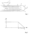
- an injection unit comprises a screw cylinder 2, in which a screw 4 with at least one screw land 6 is rotatably and axially displaceably mounted.
- a chute 12 to be plasticized material in the screw cylinder 2 and thus the screw 4 is supplied.
- the material is gripped by the rotating screw 4 with screw land 6, plasticized and conveyed into a metering chamber 8.
- a dynamic pressure builds up in the metering chamber 8, which axially displaces the screw 4 along the path s in the direction of the arrow.
- the process is terminated when the screw has reached a screw end position or metering position (not shown) in which a predetermined amount of plasticized material has collected in the metering chamber 8.
- the material is then injected via an axial injection movement of the screw via channels 10 in a mold (not shown), followed by a new dosing followed.
- a metering motor that rotatably drives the screw
- an injection motor that drives the screw for linear axial movement for injection.
- FIG. 2 shows the graph of the current axial retraction speed v s , the screw, plotted on the Schnekkenweg s in the final phase of the dosing.
- the speed of the screw starting from an initial retraction speed v 0 over a braking distance .DELTA.s be linearly reduced so that the screw comes exactly in a Schnekkenend ein s E to a standstill, that is no longer moved axially.
- ⁇ is the speed of the screw at the beginning of the braking process
- ⁇ is the braking power of the drive train, in which the inertia of the drive train, influences of converters, etc. are included.
- Values for t B and ⁇ can be easily determined by experiments, ⁇ is known, and t B can be measured.
- a newly set speed value for the rotation of the screw is thus determined from the current speed value and the current retraction speed of the screw, wherein the ratio v s to ⁇ the current capacity of the screw is taken into account.
- the current value for c can be replaced by a minimum value or a minimum speed can be set, which is set instead of the newly set speed when the new the speed to be set is below the minimum speed.
- control electronics are required with a processor for carrying out the calculations presented above and corresponding memories for storing variable and fixed values such as the clock-dependent values or the values ⁇ , a s , together with suitable converters, amplifiers, etc. for controlling the metering motor.
Landscapes
- Engineering & Computer Science (AREA)
- Manufacturing & Machinery (AREA)
- Mechanical Engineering (AREA)
- Injection Moulding Of Plastics Or The Like (AREA)
Description
- Die Erfindung bezieht sich auf ein Verfahren zum Regeln des Dosiervorgangs einer Spritzgießmaschine gemäß dem Oberbegriff des Patentanspruchs 1.
- Bekannte Spritzgießprozesse unterteilt man grob in eine Dosierphase und in eine Einspritzphase. In der Dosierphase wird in eine Schnecke zu plastifizierendes Material zugeführt und durch Drehung der Schnecke in einem Spritzzylinder plastifiziert und in einen Dosierraum transportiert. Dabei bewegt sich die Schnecke entsprechend dem zugeführten Material vom Dosierraum weg und vergrößert diesen, bis die Schnecke schließlich eine Dosierposition (Schneckenendposition) erreicht, bei der sich eine vorgegebene Materialmenge im Dosierraum befindet. In der anschließenden Einspritzphase wird das plastifizierte Material durch eine lineare Bewegung der Schnecke aus dem Dosierraum über Kanäle in ein Werkzeug (Form) eingespritzt.
- In der Dosierphase ist es erforderlich, daß die Schnecke möglichst exakt die Dosierposition oder Schneckenendstellung anläuft. Überläuft die Schnecke die Dosierposition, so sammelt sich übermäßig viel Material im Dosierraum, was bei der anschließenden Einspritzphase zu einer übermäßigen Zufuhr von Material und damit zu übermäßiger Gratbildung am zu fertigenden Werkzeug führt; erreicht die Schnecke die Dosierposition nicht, befindet sich zu wenig Material im Dosierraum, was zu Einfallstellen, Lunkern od. dgl. am Werkstück führt.
- Bei allen Spritzgießmaschinen zeigt der Antrieb eine gewisse Trägheit, die beim Anfahren der Dosierposition berücksichtigt werden muß; dieser Effekt ist insbesondere bei elektrisch betriebenen Maschinen kritisch, da deren Antriebsstrang eine hohe Trägheit aufweist.
- Aus der
JP63095927 - Aus der
DE 19619730 A1 ist eine Einspritzeinheit einer Spritzgießmaschine mit einem ersten Antriebsstrang für die Drehbewegung der Schnecke und einem zweiten Antriebsstrang für die Rückbewegung der Schnecke bekannt. Damit können die Drehgeschwindigkeit bzw. Schneckendrehzahl einerseits und die Rückzugsgeschwindigkeit andererseits unabhängig voneinander geregelt werden. Somit kann unabhängig vom Staudruck im Schneckenvorraum direkt das Verhältnis von Dreh- und Rückzugsgeschwindigkeit der Schnecke eingestellt werden. - Ein Verfahren gemäß dem Oberbegriff des Patentanspruchs 1 ist aus der
EP 0 245 522 A1 bekannt. Bei diesem Verfahren wird die Drehzahl der Schnecke in der Dosierphase eine vorgegebene Strecke vor der Dosierposition auf einen Minimalwert verändert, so daß beim Anhalten der Schnecke in der Dosierposition nur geringe Trägheitskräfte auftreten. - Dabei ist jedoch zu berücksichtigen, daß die verfahrenstechnischen Gegebenheiten beim Dosieren von Kunststoff nicht immer konstant sind; das gilt insbesondere in Bezug auf das Einzugsverhalten der Schnecke, d. h. in welchem Maße das Material in die Schnecke eingezogen und plastifiziert wird. Dies hat bei den üblichen Verfahren mit einer vorbestimmten Abschaltsequenz den Nachteil, daß der effektive Abschaltpunkt und damit die Schneckenendposition variieren kann.
- Demgegenüber liegt der Erfindung die Aufgabe zugrunde, ein Verfahren zum Regeln des Dosiervorgangs einer Spritzgießmaschine anzugeben, bei dem eine Schneckenendstellung (Dosierposition) immer exakt erreicht werden kann.
- Die Lösung dieser Aufgabe erfolgt durch ein Verfahren mit den Merkmalen des Patentanspruchs 1; die abhängigen Ansprüche betreffen vorteilhafte Weiterentwicklungen der Erfindung.
- Der Erfindung liegt die Erkenntnis zugrunde, daß in der Regel die axiale Rückzugsgeschwindigkeit und die dazu erforderliche Drehzahl der Schnecke nicht linear voneinander abhängen. Das Verhältnis von axialer Rückzugsgeschwindigkeit der Schnecke und der dazu erforderlichen Drehzahl gibt so- mit das Fördervermögen der Schnecke bei dieser Drehzahl an, und in dieses Fördervermögen gehen verschiedene Parameter wie Temperatur des zu verarbeitenden Materials, physikalische Beschaffenheit des zugeführten Materials, Einzugsverhalten der Schnecke, Konsistenz des Materials etc. ein. Diese Parameter können implizit berücksichtigt werden, wenn man zumindest in der Endphase des Dosiervorgangs die Drehzahl der Schnecke abhängig von der aktuellen axialen Geschwindigkeit der Schnecke Vermiudwt. Dies verändert wiederum die aktuelle Rückzugsgeschwindigkeit der Schnecke, die auf diese Weise linear von der Zeit abhängig vermindert werden kann, so daß die Schnecke exakt die Schneckenendstellung bzw. die Dosierposition erreicht.
- Vorzugsweise wird das Regelverfahren als iterativer Prozeß durchgeführt, bei dem eine neu einzustellende Drehzahl der Schnecke aus der aktuellen Drehzahl sowie aus dem Verhältnis der aktuellen Drehzahl und der aktuellen axialen Rückzugsgeschwindigkeit der Schnecke ermittelt wird.
- Dabei wird vorzugsweise eine Minimaldrehzahl eingestellt, wenn die neu einzustellende Drehzahl unterhalb der Minimaldrehzahl liegt.
- Ein Ausführungsbeispiel der Erfindung wird anhand der beigefügten Zeichnungen erläutert. Es zeigt:
- Fig. 1
- den schematischen Ausbau einer Einspritzeinheit und
- Fig. 2
- ein Geschwindigkeits-Ortsdiagramm für die Dosier- phase.
- Gemäß der schematischen Darstellung in der
Figur 1 umfaßt eine Einspritzeinheit einen Schneckenzylinder 2, in dem eine Schnecke 4 mit mindestens einem Schneckensteg 6 drehbar und axial verschieblich gelagert ist. - Über eine Schütte 12 wird zu plastifizierendes Material in den Schneckenzylinder 2 und damit der Schnecke 4 zugeführt. Das Material wird von der sich drehenden Schnecke 4 mit Schneckensteg 6 ergriffen, plastifiziert und in einen Dosierraum 8 gefördert. Durch das sich im Dosierraum 8 ansammelnde Material baut sich im Dosierraum 8 ein Staudruck auf, der die Schnecke 4 entlang der Strecke s in Richtung des Pfeils axial verschiebt. Der Vorgang wird beendet, wenn die Schnecke eine Schneckenendstellung oder Dosierposition (nicht dargestellt) erreicht hat, in der sich im Dosierraum 8 eine vorgegebene Menge plastifizierten Materials gesammelt hat. Das Material wird anschließend über eine axiale Einspritzbewegung der Schnecke über Kanäle 10 in ein Formwerkzeug (nicht dargestellt) eingespritzt, worauf sich ein neuer Dosiervorgang anschließt.
- Nicht in den Zeichnungen dargestellt ist ein Dosiermotor, der die Schnecke rotatorisch antreibt, sowie ein Einspritzmotor, der die Schnecke für eine lineare Axialbewegung zum Einspritzen antreibt. Der generelle Aufbau von Spritzgießeinheiten ist allgemein bekannt und wird deshalb nicht weiter erläutert.
-
Figur 2 zeigt den Graphen der aktuellen axialen Rückzugsgeschwindigkeit vs, der Schnecke, aufgetragen über dem Schnekkenweg s in der Endphase des Dosiervorgangs. Dabei soll die Geschwindigkeit der Schnecke ausgehend von einer Anfangs-Rückzugsgeschwindigkeit v0 über einen Bremsweg Δs linear so vermindert werden, daß die Schnecke exakt in einer Schnekkenendstellung sE zum Stillstand kommt, d. h. sich nicht mehr axial bewegt. - Zur Ermittlung von Δs wird dem Dosierantriebsstrang eine Bremszeit tB zugeschrieben, und zwar nach der Beziehung

- Dabei ist ω die Drehzahl der Schnecke zu Beginn des Bremsvorganges, und α ist das Bremsvermögen des Antriebsstrangs, in das die Trägheit des Antriebsstrangs, Einflüsse von Umrichtern etc. einfließen. Werte für tB bzw. α können in einfacher Weise durch Versuche ermittelt werden, ω ist bekannt, und tB kann gemessen werden.
- Analog zur rotatorischen Bewegung der Schnecke kann man für die Abbremsung der linearen Axialbewegung eine Beschleunigung as definieren, durch

wobei v0 die axiale Rückzugsgeschwindigkeit der Schnecke zu Beginn des Bremsvorgangs ist. - Daraus folgt nach Regeln der klassischen Kinematik für den Bremsweg Δs:

- Durch den so ermittelten Wert von Δs wird der vor der Schneckenendposition sE liegende Abstand angegeben, bei dem der Bremsvorgang einzuleiten ist.
- Vorzugsweise wird dabei die axiale Rückzugsgeschwindigkeit vs der Schnecke in diskreten Schritten oder Takten verändert, wobei für den i-ten Takt gilt:

wobei vs(i+1) ein neuer Geschwindigkeitswert ist, vs(i) die aktuelle Geschwindigkeit und Δt die Taktzeit jedes Schrittes ist. - Das Fördervermögen c, d. h. die Beziehung zwischen ω und vs kann für den i-ten Schritt ausgedrückt werden als

- Eingesetzt in Gleichung (4) folgt daraus

- Unter der Annahme, daß sich in den relativ kurzen Taktzeiten eines Rechenalgorithmus sich c nicht wesentlich innerhalb eines Taktes ändert, kann c(i+1) ersetzt werden durch c(i), so daß schließlich folgt

- Ein neu einzustellender Drehzahlwert für die Drehung der Schnecke wird somit ermittelt aus dem aktuellen Drehzahlwert sowie der aktuellen Rückzugsgeschwindigkeit der Schnecke, wobei durch das Verhältnis vs zu ω das aktuelle Fördervermögen der Schnecke berücksichtigt wird.
- Sollte das Fördervermögen unter einen Minimalwert fallen, bei dem beispielsweise die Schnecke trotz Drehung nicht fördert, so kann der aktuelle Wert für c durch einen Minimalwert ersetzt werden bzw. kann eine Mindestdrehzahl festgelegt werden, die statt der neu einzustellenden Drehzahl eingestellt wird, wenn die neu einzustellende Drehzahl unter der Mindestdrehzahl liegt.
- In welcher Weise das oben dargestellte Verfahren in eine Spritzgießmaschine implementiert wird, ist dem Fachmann geläufig. Dazu muß eine Wegmessung durchgeführt werden, um festzustellen, wann die Schnecke den Abstand Δs zu der Schneckenendposition sE erreicht hat sowie Mittel zur Ermittlung der aktuellen Drehzahl und Rückzugsgeschwindigkeit. Ferner ist eine Steuerelektronik erforderlich mit einem Prozessor zur Durchführung der oben dargestellten Berechnungen sowie entsprechenden Speichern zur Speicherung variabler und fixer Werte wie der taktabhängigen Werte bzw. der Werte α, as, zusammen mit geeigneten Umrichtern, Verstärkern, etc. zur Ansteuerung des Dosiermotors.
Claims (4)
- Verfahren zum Regeln des Dosiervorgangs einer Spritzgießmaschine, bei der Material von einer rotierenden Schnecke (4) plastifiziert und in einen Dosierraum (8) gefördert wird, wobei sich im Dosierraum (8) ein Staudruck aufbaut, der die Schnecke (4) mit einer axialen Rückzugsgeschwindigkeit (vs) axial auf eine Dosierposition (sE) verschiebt, wobei man die Drehzahl (w) der Schnecke vor Erreichen der Dosierposition (sE) in Abhängigkeit von der axialen Rückzugsgeschwindigkeit (vs) vermindert,
dadurch gekennzeichnet,
dass man einen neu einzustellenden Drehzahlwert der Schnecke in Abhängigkeit von einem aktuellen Drehzahlwert und einer aktuellen Rückzugsgeschwindigkeit der Schnecke berechnet. - Verfahren nach Anspruch 1, dadurch gekennzeichnet, dass man iterativ neue Drehzahlwerte ω(i+1) für die Schnecke (4) aus der folgenden Beziehung ermittelt:
 wobei ω(i) der aktuelle Drehzahlwert im i-ten Schritt ist, v(i) der aktuelle Wert für die Rückzugsgeschwindigkeit im i-ten Schritt ist,as die Axialbeschleunigung zum linearen Abbremsen der Schnecke ist undΔt die Taktzeit jeden Schrittes ist.
 - Verfahren nach Anspruch 2, dadurch gekennzeichnet, dass man ω(i) durch eine vorgegebene Minimaldrehzahl ersetzt, wenn ω(i+1) kleiner ist als die Mindestdrehzahl.
- Verfahren nach Anspruch 1 bis 3, dadurch gekennzeichnet, dass man die Drehzahlverminderung auslöst, wenn die Schnecke den Anfang einer Bremsstrecke Δs vor der Dosierposition (sE) erreicht hat, wobei Δs gegeben ist durch

und wobei v0 die Rückzugsgeschwindigkeit der Schnecke bei Erreichen der Bremsstrecke und tB eine Bremszeit des Systems bezeichnet.
Applications Claiming Priority (3)
| Application Number | Priority Date | Filing Date | Title |
|---|---|---|---|
| DE10154615A DE10154615A1 (de) | 2001-11-07 | 2001-11-07 | Verfahren zum Regeln des Dosiervorgangs einer Spritzgießmaschine |
| DE10154615 | 2001-11-07 | ||
| PCT/EP2002/012391 WO2003039839A1 (de) | 2001-11-07 | 2002-11-06 | Verfahren zum regeln des dosiervorgangs einer spritzgiessmaschine |
Publications (2)
| Publication Number | Publication Date |
|---|---|
| EP1465761A1 EP1465761A1 (de) | 2004-10-13 |
| EP1465761B1 true EP1465761B1 (de) | 2011-01-12 |
Family
ID=7704868
Family Applications (1)
| Application Number | Title | Priority Date | Filing Date |
|---|---|---|---|
| EP02792736A Expired - Lifetime EP1465761B1 (de) | 2001-11-07 | 2002-11-06 | Verfahren zum regeln des dosiervorgangs einer spritzgiessmaschine |
Country Status (4)
| Country | Link |
|---|---|
| EP (1) | EP1465761B1 (de) |
| AT (1) | ATE495003T1 (de) |
| DE (2) | DE10154615A1 (de) |
| WO (1) | WO2003039839A1 (de) |
Families Citing this family (1)
| Publication number | Priority date | Publication date | Assignee | Title |
|---|---|---|---|---|
| DE102022127090A1 (de) | 2022-10-17 | 2024-04-18 | Arburg Gmbh + Co Kg | Antriebssynchronisierte Dosierregelung sowie damit arbeitende Spritzgießmaschine |
Family Cites Families (14)
| Publication number | Priority date | Publication date | Assignee | Title |
|---|---|---|---|---|
| CH555738A (de) * | 1973-03-09 | 1974-11-15 | Netstal Ag Maschf Giesserei | Kunstsoff-spritzgiessmaschine. |
| DE3586576T2 (de) * | 1984-06-25 | 1993-01-07 | Toshiba Machine Co Ltd | Spritzgiessmaschinen und verfahren zu deren kontrolle. |
| JPS61121921A (ja) * | 1984-11-19 | 1986-06-09 | Japan Steel Works Ltd:The | 射出成形機の計量速度制御方法 |
| JPS61158417A (ja) * | 1984-12-30 | 1986-07-18 | Meiki Co Ltd | 黒鉛化方法 |
| WO1986007561A1 (fr) * | 1985-06-17 | 1986-12-31 | Katashi Aoki | Procede d'injection de matiere et appareil de mesure de matiere pour machines de moulage par injection |
| JPH0661800B2 (ja) * | 1986-10-13 | 1994-08-17 | 住友重機械工業株式会社 | 射出成形機の計量制御装置 |
| JPS63236618A (ja) * | 1987-03-25 | 1988-10-03 | Meiki Co Ltd | インラインスクリュ式射出成形機における成形材料の可塑化制御方法 |
| US5028373A (en) * | 1990-01-18 | 1991-07-02 | Toyo Machinery & Metal Co., Ltd. | Method for controlling injection unit of injection molding machine |
| JPH0414424A (ja) * | 1990-05-08 | 1992-01-20 | Mitsubishi Heavy Ind Ltd | 射出成形機の可塑化工程制御方法 |
| JP2857925B2 (ja) * | 1990-10-09 | 1999-02-17 | 住友重機械工業株式会社 | インラインスクリュー型射出成形機 |
| JP2866019B2 (ja) * | 1995-01-27 | 1999-03-08 | 住友重機械工業株式会社 | 電動射出成形機の射出装置 |
| JP2000015675A (ja) * | 1998-07-01 | 2000-01-18 | Teijin Ltd | 薄肉板状成形品の射出成形方法 |
| JP3056215B1 (ja) * | 1999-05-25 | 2000-06-26 | ファナック株式会社 | 射出成形機の計量制御装置 |
| JP3686328B2 (ja) * | 2000-11-15 | 2005-08-24 | 住友重機械工業株式会社 | 射出成形機の制御方法 |
-
2001
- 2001-11-07 DE DE10154615A patent/DE10154615A1/de not_active Withdrawn
-
2002
- 2002-11-06 WO PCT/EP2002/012391 patent/WO2003039839A1/de not_active Ceased
- 2002-11-06 EP EP02792736A patent/EP1465761B1/de not_active Expired - Lifetime
- 2002-11-06 DE DE50214863T patent/DE50214863D1/de not_active Expired - Lifetime
- 2002-11-06 AT AT02792736T patent/ATE495003T1/de active
Also Published As
| Publication number | Publication date |
|---|---|
| EP1465761A1 (de) | 2004-10-13 |
| ATE495003T1 (de) | 2011-01-15 |
| DE10154615A1 (de) | 2003-05-22 |
| WO2003039839A1 (de) | 2003-05-15 |
| DE50214863D1 (de) | 2011-02-24 |
Similar Documents
| Publication | Publication Date | Title |
|---|---|---|
| DE3811183C2 (de) | Gewindeschneidmaschine | |
| DE4345034B4 (de) | Spritzgießmaschine mit elektrischem Antrieb sowie Verfahren zur Führung derselben | |
| DE69113128T2 (de) | Spritzgusssteuerung mit veränderbar geregeltem Lernverfahren. | |
| EP0185984B1 (de) | Hydraulikeinrichtung für die Spritzgiesseinheit einer Kunststoff-Spritzgiessmaschine | |
| DE102012018748B4 (de) | Fehlererfassungsvorrichtung für eine Spritzgussmaschine | |
| DE69113869T2 (de) | Spritzgiesssteuerung mit prozessvariablem Lernverfahren. | |
| DE3586576T2 (de) | Spritzgiessmaschinen und verfahren zu deren kontrolle. | |
| DE10135345B4 (de) | Elektrische Spritzgussmaschine und Verfahren zum Steuern einer elektrischen Spritzgussmaschine | |
| DE2745914A1 (de) | Numerische steuerung fuer die treibereinrichtung von schrittmotoren | |
| CH642905A5 (de) | Spritzgiessmaschine. | |
| DE112007002616T5 (de) | Servopressvorrichtung und Steuerverfahren für dieselbe | |
| AT395557B (de) | Spritzgussvorrichtung zur herstellung von formteilen aus thermoplastischem kunststoff | |
| DE19652564B4 (de) | Verfahren zum Betreiben eines Antriebs einer Spritzgießmaschine | |
| EP0707936B1 (de) | Verfahren zur Bestimmung des Umschaltpunktes bei der Herstellung eines Spritzgussteils | |
| DE3889126T2 (de) | Steuerungseinheit einer spritzgiessmaschine. | |
| DE19721272B4 (de) | Elektrische Preßvorrichtung | |
| DE102009018071A1 (de) | Verfahren und Regelvorrichtung zur Regelung einer Druckmittelzufuhr für einen hydraulischen Aktor | |
| EP3915755B1 (de) | Managementverfahren und managementsystem zur steuerung einer gesamtanlage | |
| EP1215030A2 (de) | Einspritzgerät für eine Spritzgiessmaschine | |
| DE69118298T2 (de) | Spritzgiessmaschine mit Steuermittel für den Antrieb der Schnecke | |
| EP0862058A1 (de) | Verfahren zur Offsetkorrektur eines Sensorausgangssignals | |
| EP4299904B1 (de) | Verfahren zur regelung von drehzahlvariablen fluidpumpen | |
| DE10154615A1 (de) | Verfahren zum Regeln des Dosiervorgangs einer Spritzgießmaschine | |
| DE102023119617A1 (de) | Verfahren zum Einrichten und Betreiben von Maschinen zur Verarbeitung von Kunststoffen | |
| EP3157727B1 (de) | Verfahren zum betreiben einer spritzgiessmaschine |
Legal Events
| Date | Code | Title | Description |
|---|---|---|---|
| PUAI | Public reference made under article 153(3) epc to a published international application that has entered the european phase |
Free format text: ORIGINAL CODE: 0009012 |
|
| 17P | Request for examination filed |
Effective date: 20040607 |
|
| AK | Designated contracting states |
Kind code of ref document: A1 Designated state(s): AT BE BG CH CY CZ DE DK EE ES FI FR GB GR IE IT LI LU MC NL PT SE SK TR |
|
| AX | Request for extension of the european patent |
Extension state: AL LT LV MK RO SI |
|
| 17Q | First examination report despatched |
Effective date: 20041115 |
|
| RAP1 | Party data changed (applicant data changed or rights of an application transferred) |
Owner name: KRAUSS MAFFEI GMBH |
|
| RAP1 | Party data changed (applicant data changed or rights of an application transferred) |
Owner name: KRAUSMAFFEI TECHNOLOGIES GMBH |
|
| RAP1 | Party data changed (applicant data changed or rights of an application transferred) |
Owner name: KRAUSSMAFFEI TECHNOLOGIES GMBH |
|
| GRAP | Despatch of communication of intention to grant a patent |
Free format text: ORIGINAL CODE: EPIDOSNIGR1 |
|
| GRAS | Grant fee paid |
Free format text: ORIGINAL CODE: EPIDOSNIGR3 |
|
| GRAA | (expected) grant |
Free format text: ORIGINAL CODE: 0009210 |
|
| AK | Designated contracting states |
Kind code of ref document: B1 Designated state(s): AT BE BG CH CY CZ DE DK EE ES FI FR GB GR IE IT LI LU MC NL PT SE SK TR |
|
| REG | Reference to a national code |
Ref country code: GB Ref legal event code: FG4D Free format text: NOT ENGLISH |
|
| REG | Reference to a national code |
Ref country code: CH Ref legal event code: NV Representative=s name: KIRKER & CIE S.A. Ref country code: CH Ref legal event code: EP |
|
| REG | Reference to a national code |
Ref country code: IE Ref legal event code: FG4D Free format text: LANGUAGE OF EP DOCUMENT: GERMAN |
|
| REF | Corresponds to: |
Ref document number: 50214863 Country of ref document: DE Date of ref document: 20110224 Kind code of ref document: P |
|
| REG | Reference to a national code |
Ref country code: DE Ref legal event code: R096 Ref document number: 50214863 Country of ref document: DE Effective date: 20110224 |
|
| REG | Reference to a national code |
Ref country code: NL Ref legal event code: VDEP Effective date: 20110112 |
|
| PG25 | Lapsed in a contracting state [announced via postgrant information from national office to epo] |
Ref country code: ES Free format text: LAPSE BECAUSE OF FAILURE TO SUBMIT A TRANSLATION OF THE DESCRIPTION OR TO PAY THE FEE WITHIN THE PRESCRIBED TIME-LIMIT Effective date: 20110423 Ref country code: GR Free format text: LAPSE BECAUSE OF FAILURE TO SUBMIT A TRANSLATION OF THE DESCRIPTION OR TO PAY THE FEE WITHIN THE PRESCRIBED TIME-LIMIT Effective date: 20110413 Ref country code: PT Free format text: LAPSE BECAUSE OF FAILURE TO SUBMIT A TRANSLATION OF THE DESCRIPTION OR TO PAY THE FEE WITHIN THE PRESCRIBED TIME-LIMIT Effective date: 20110512 Ref country code: SE Free format text: LAPSE BECAUSE OF FAILURE TO SUBMIT A TRANSLATION OF THE DESCRIPTION OR TO PAY THE FEE WITHIN THE PRESCRIBED TIME-LIMIT Effective date: 20110112 |
|
| REG | Reference to a national code |
Ref country code: IE Ref legal event code: FD4D |
|
| PG25 | Lapsed in a contracting state [announced via postgrant information from national office to epo] |
Ref country code: NL Free format text: LAPSE BECAUSE OF FAILURE TO SUBMIT A TRANSLATION OF THE DESCRIPTION OR TO PAY THE FEE WITHIN THE PRESCRIBED TIME-LIMIT Effective date: 20110112 Ref country code: FI Free format text: LAPSE BECAUSE OF FAILURE TO SUBMIT A TRANSLATION OF THE DESCRIPTION OR TO PAY THE FEE WITHIN THE PRESCRIBED TIME-LIMIT Effective date: 20110112 Ref country code: BG Free format text: LAPSE BECAUSE OF FAILURE TO SUBMIT A TRANSLATION OF THE DESCRIPTION OR TO PAY THE FEE WITHIN THE PRESCRIBED TIME-LIMIT Effective date: 20110412 Ref country code: CY Free format text: LAPSE BECAUSE OF FAILURE TO SUBMIT A TRANSLATION OF THE DESCRIPTION OR TO PAY THE FEE WITHIN THE PRESCRIBED TIME-LIMIT Effective date: 20110112 |
|
| PG25 | Lapsed in a contracting state [announced via postgrant information from national office to epo] |
Ref country code: DK Free format text: LAPSE BECAUSE OF FAILURE TO SUBMIT A TRANSLATION OF THE DESCRIPTION OR TO PAY THE FEE WITHIN THE PRESCRIBED TIME-LIMIT Effective date: 20110112 Ref country code: IE Free format text: LAPSE BECAUSE OF FAILURE TO SUBMIT A TRANSLATION OF THE DESCRIPTION OR TO PAY THE FEE WITHIN THE PRESCRIBED TIME-LIMIT Effective date: 20110112 Ref country code: EE Free format text: LAPSE BECAUSE OF FAILURE TO SUBMIT A TRANSLATION OF THE DESCRIPTION OR TO PAY THE FEE WITHIN THE PRESCRIBED TIME-LIMIT Effective date: 20110112 |
|
| PLBE | No opposition filed within time limit |
Free format text: ORIGINAL CODE: 0009261 |
|
| STAA | Information on the status of an ep patent application or granted ep patent |
Free format text: STATUS: NO OPPOSITION FILED WITHIN TIME LIMIT |
|
| PG25 | Lapsed in a contracting state [announced via postgrant information from national office to epo] |
Ref country code: SK Free format text: LAPSE BECAUSE OF FAILURE TO SUBMIT A TRANSLATION OF THE DESCRIPTION OR TO PAY THE FEE WITHIN THE PRESCRIBED TIME-LIMIT Effective date: 20110112 Ref country code: CZ Free format text: LAPSE BECAUSE OF FAILURE TO SUBMIT A TRANSLATION OF THE DESCRIPTION OR TO PAY THE FEE WITHIN THE PRESCRIBED TIME-LIMIT Effective date: 20110112 |
|
| 26N | No opposition filed |
Effective date: 20111013 |
|
| PG25 | Lapsed in a contracting state [announced via postgrant information from national office to epo] |
Ref country code: IT Free format text: LAPSE BECAUSE OF FAILURE TO SUBMIT A TRANSLATION OF THE DESCRIPTION OR TO PAY THE FEE WITHIN THE PRESCRIBED TIME-LIMIT Effective date: 20110112 |
|
| REG | Reference to a national code |
Ref country code: DE Ref legal event code: R097 Ref document number: 50214863 Country of ref document: DE Effective date: 20111013 |
|
| BERE | Be: lapsed |
Owner name: KRAUSSMAFFEI TECHNOLOGIES G.M.B.H. Effective date: 20111130 |
|
| PG25 | Lapsed in a contracting state [announced via postgrant information from national office to epo] |
Ref country code: MC Free format text: LAPSE BECAUSE OF NON-PAYMENT OF DUE FEES Effective date: 20111130 |
|
| GBPC | Gb: european patent ceased through non-payment of renewal fee |
Effective date: 20111106 |
|
| REG | Reference to a national code |
Ref country code: FR Ref legal event code: ST Effective date: 20120731 |
|
| PG25 | Lapsed in a contracting state [announced via postgrant information from national office to epo] |
Ref country code: BE Free format text: LAPSE BECAUSE OF NON-PAYMENT OF DUE FEES Effective date: 20111130 |
|
| PG25 | Lapsed in a contracting state [announced via postgrant information from national office to epo] |
Ref country code: GB Free format text: LAPSE BECAUSE OF NON-PAYMENT OF DUE FEES Effective date: 20111106 |
|
| PG25 | Lapsed in a contracting state [announced via postgrant information from national office to epo] |
Ref country code: FR Free format text: LAPSE BECAUSE OF NON-PAYMENT OF DUE FEES Effective date: 20111130 |
|
| PG25 | Lapsed in a contracting state [announced via postgrant information from national office to epo] |
Ref country code: LU Free format text: LAPSE BECAUSE OF NON-PAYMENT OF DUE FEES Effective date: 20111106 |
|
| REG | Reference to a national code |
Ref country code: DE Ref legal event code: R082 Ref document number: 50214863 Country of ref document: DE Representative=s name: WILHELM, LUDWIG, DIPL.-PHYS., DE |
|
| REG | Reference to a national code |
Ref country code: DE Ref legal event code: R082 Ref document number: 50214863 Country of ref document: DE Representative=s name: WILHELM, LUDWIG, DIPL.-PHYS., DE Effective date: 20130603 Ref country code: DE Ref legal event code: R081 Ref document number: 50214863 Country of ref document: DE Owner name: KRAUSSMAFFEI TECHNOLOGIES GMBH, DE Free format text: FORMER OWNER: KRAUSMAFFEI TECHNOLOGIES GMBH, 80997 MUENCHEN, DE Effective date: 20130603 |
|
| PG25 | Lapsed in a contracting state [announced via postgrant information from national office to epo] |
Ref country code: TR Free format text: LAPSE BECAUSE OF FAILURE TO SUBMIT A TRANSLATION OF THE DESCRIPTION OR TO PAY THE FEE WITHIN THE PRESCRIBED TIME-LIMIT Effective date: 20110112 |
|
| PGFP | Annual fee paid to national office [announced via postgrant information from national office to epo] |
Ref country code: CH Payment date: 20151118 Year of fee payment: 14 |
|
| REG | Reference to a national code |
Ref country code: AT Ref legal event code: PC Ref document number: 495003 Country of ref document: AT Kind code of ref document: T Owner name: KRAUSSMAFFEI TECHNOLOGIES GMBH, DE Effective date: 20160706 |
|
| REG | Reference to a national code |
Ref country code: CH Ref legal event code: PL |
|
| PG25 | Lapsed in a contracting state [announced via postgrant information from national office to epo] |
Ref country code: LI Free format text: LAPSE BECAUSE OF NON-PAYMENT OF DUE FEES Effective date: 20161130 Ref country code: CH Free format text: LAPSE BECAUSE OF NON-PAYMENT OF DUE FEES Effective date: 20161130 |
|
| PGFP | Annual fee paid to national office [announced via postgrant information from national office to epo] |
Ref country code: AT Payment date: 20201119 Year of fee payment: 19 Ref country code: DE Payment date: 20201119 Year of fee payment: 19 |
|
| REG | Reference to a national code |
Ref country code: DE Ref legal event code: R119 Ref document number: 50214863 Country of ref document: DE |
|
| REG | Reference to a national code |
Ref country code: AT Ref legal event code: MM01 Ref document number: 495003 Country of ref document: AT Kind code of ref document: T Effective date: 20211106 |
|
| PG25 | Lapsed in a contracting state [announced via postgrant information from national office to epo] |
Ref country code: AT Free format text: LAPSE BECAUSE OF NON-PAYMENT OF DUE FEES Effective date: 20211106 |
|
| PG25 | Lapsed in a contracting state [announced via postgrant information from national office to epo] |
Ref country code: DE Free format text: LAPSE BECAUSE OF NON-PAYMENT OF DUE FEES Effective date: 20220601 |