EP1465531B1 - High frequency high frame-rate ultrasound imaging system - Google Patents
High frequency high frame-rate ultrasound imaging system Download PDFInfo
- Publication number
- EP1465531B1 EP1465531B1 EP20030776327 EP03776327A EP1465531B1 EP 1465531 B1 EP1465531 B1 EP 1465531B1 EP 20030776327 EP20030776327 EP 20030776327 EP 03776327 A EP03776327 A EP 03776327A EP 1465531 B1 EP1465531 B1 EP 1465531B1
- Authority
- EP
- European Patent Office
- Prior art keywords
- transducer
- ultrasound
- acoustic window
- scanhead
- acoustic
- Prior art date
- Legal status (The legal status is an assumption and is not a legal conclusion. Google has not performed a legal analysis and makes no representation as to the accuracy of the status listed.)
- Expired - Lifetime
Links
- 238000012285 ultrasound imaging Methods 0.000 title description 16
- 238000002604 ultrasonography Methods 0.000 claims description 77
- 239000012530 fluid Substances 0.000 claims description 43
- 239000000463 material Substances 0.000 claims description 26
- 239000012528 membrane Substances 0.000 claims description 24
- 230000003287 optical effect Effects 0.000 claims description 19
- 230000008878 coupling Effects 0.000 claims description 15
- 238000010168 coupling process Methods 0.000 claims description 15
- 238000005859 coupling reaction Methods 0.000 claims description 15
- -1 polyethylene Polymers 0.000 claims description 8
- 239000004417 polycarbonate Substances 0.000 claims description 6
- 229920000515 polycarbonate Polymers 0.000 claims description 6
- 229920001684 low density polyethylene Polymers 0.000 claims description 5
- 239000004702 low-density polyethylene Substances 0.000 claims description 5
- 239000004698 Polyethylene Substances 0.000 claims description 4
- 238000002592 echocardiography Methods 0.000 claims description 4
- 229920000573 polyethylene Polymers 0.000 claims description 4
- 238000012545 processing Methods 0.000 claims description 4
- 229920002379 silicone rubber Polymers 0.000 claims description 4
- 239000004743 Polypropylene Substances 0.000 claims description 3
- 229920003182 Surlyn® Polymers 0.000 claims description 3
- 239000005035 Surlyn® Substances 0.000 claims description 3
- NIXOWILDQLNWCW-UHFFFAOYSA-N acrylic acid group Chemical group C(C=C)(=O)O NIXOWILDQLNWCW-UHFFFAOYSA-N 0.000 claims description 3
- 229920000728 polyester Polymers 0.000 claims description 3
- 229920000306 polymethylpentene Polymers 0.000 claims description 3
- 229920001155 polypropylene Polymers 0.000 claims description 3
- 229920002799 BoPET Polymers 0.000 claims description 2
- 229920006362 Teflon® Polymers 0.000 claims description 2
- 229920000554 ionomer Polymers 0.000 claims description 2
- 229920003223 poly(pyromellitimide-1,4-diphenyl ether) Polymers 0.000 claims description 2
- 229920006264 polyurethane film Polymers 0.000 claims description 2
- 229920002725 thermoplastic elastomer Polymers 0.000 claims description 2
- 239000011116 polymethylpentene Substances 0.000 claims 2
- 230000033001 locomotion Effects 0.000 description 14
- 239000000523 sample Substances 0.000 description 12
- 238000003384 imaging method Methods 0.000 description 10
- XEEYBQQBJWHFJM-UHFFFAOYSA-N Iron Chemical compound [Fe] XEEYBQQBJWHFJM-UHFFFAOYSA-N 0.000 description 8
- XLYOFNOQVPJJNP-UHFFFAOYSA-N water Substances O XLYOFNOQVPJJNP-UHFFFAOYSA-N 0.000 description 8
- 230000006870 function Effects 0.000 description 7
- LYCAIKOWRPUZTN-UHFFFAOYSA-N Ethylene glycol Chemical compound OCCO LYCAIKOWRPUZTN-UHFFFAOYSA-N 0.000 description 6
- 238000000034 method Methods 0.000 description 6
- 229920003023 plastic Polymers 0.000 description 5
- 230000005540 biological transmission Effects 0.000 description 4
- 238000013461 design Methods 0.000 description 4
- 238000010586 diagram Methods 0.000 description 4
- 229920001971 elastomer Polymers 0.000 description 4
- 229910052742 iron Inorganic materials 0.000 description 4
- 230000007246 mechanism Effects 0.000 description 4
- 239000004033 plastic Substances 0.000 description 4
- 210000001161 mammalian embryo Anatomy 0.000 description 3
- 238000004519 manufacturing process Methods 0.000 description 3
- 229920001343 polytetrafluoroethylene Polymers 0.000 description 3
- 239000004810 polytetrafluoroethylene Substances 0.000 description 3
- 230000008569 process Effects 0.000 description 3
- 239000004065 semiconductor Substances 0.000 description 3
- 239000007787 solid Substances 0.000 description 3
- 238000004804 winding Methods 0.000 description 3
- 239000005662 Paraffin oil Substances 0.000 description 2
- 229910000639 Spring steel Inorganic materials 0.000 description 2
- 239000000853 adhesive Substances 0.000 description 2
- 230000001070 adhesive effect Effects 0.000 description 2
- 239000007864 aqueous solution Substances 0.000 description 2
- 238000005452 bending Methods 0.000 description 2
- 230000008901 benefit Effects 0.000 description 2
- 239000004020 conductor Substances 0.000 description 2
- 238000011109 contamination Methods 0.000 description 2
- 239000000806 elastomer Substances 0.000 description 2
- 238000005516 engineering process Methods 0.000 description 2
- 150000002334 glycols Chemical class 0.000 description 2
- 239000002991 molded plastic Substances 0.000 description 2
- 238000012544 monitoring process Methods 0.000 description 2
- 210000000056 organ Anatomy 0.000 description 2
- 239000005060 rubber Substances 0.000 description 2
- 238000007789 sealing Methods 0.000 description 2
- 238000003860 storage Methods 0.000 description 2
- 238000012360 testing method Methods 0.000 description 2
- ZIBGPFATKBEMQZ-UHFFFAOYSA-N triethylene glycol Chemical compound OCCOCCOCCO ZIBGPFATKBEMQZ-UHFFFAOYSA-N 0.000 description 2
- 210000004291 uterus Anatomy 0.000 description 2
- 238000012795 verification Methods 0.000 description 2
- 230000000007 visual effect Effects 0.000 description 2
- 241001465754 Metazoa Species 0.000 description 1
- QJVKUMXDEUEQLH-UHFFFAOYSA-N [B].[Fe].[Nd] Chemical compound [B].[Fe].[Nd] QJVKUMXDEUEQLH-UHFFFAOYSA-N 0.000 description 1
- 230000009471 action Effects 0.000 description 1
- 210000003484 anatomy Anatomy 0.000 description 1
- 238000003491 array Methods 0.000 description 1
- 239000012620 biological material Substances 0.000 description 1
- 239000008280 blood Substances 0.000 description 1
- 210000004369 blood Anatomy 0.000 description 1
- 210000004556 brain Anatomy 0.000 description 1
- 230000015556 catabolic process Effects 0.000 description 1
- 230000000295 complement effect Effects 0.000 description 1
- 239000002131 composite material Substances 0.000 description 1
- 230000001010 compromised effect Effects 0.000 description 1
- 238000010276 construction Methods 0.000 description 1
- 238000011161 development Methods 0.000 description 1
- 238000002059 diagnostic imaging Methods 0.000 description 1
- 239000012799 electrically-conductive coating Substances 0.000 description 1
- 238000005538 encapsulation Methods 0.000 description 1
- 230000002708 enhancing effect Effects 0.000 description 1
- 239000010408 film Substances 0.000 description 1
- 239000006260 foam Substances 0.000 description 1
- 239000011521 glass Substances 0.000 description 1
- 239000003292 glue Substances 0.000 description 1
- 238000007654 immersion Methods 0.000 description 1
- 238000002347 injection Methods 0.000 description 1
- 239000007924 injection Substances 0.000 description 1
- 238000007689 inspection Methods 0.000 description 1
- 230000003993 interaction Effects 0.000 description 1
- 238000002955 isolation Methods 0.000 description 1
- 210000003734 kidney Anatomy 0.000 description 1
- 229920000126 latex Polymers 0.000 description 1
- 239000011344 liquid material Substances 0.000 description 1
- 210000004185 liver Anatomy 0.000 description 1
- 210000004072 lung Anatomy 0.000 description 1
- 229910001172 neodymium magnet Inorganic materials 0.000 description 1
- 230000001613 neoplastic effect Effects 0.000 description 1
- 230000007935 neutral effect Effects 0.000 description 1
- 239000013307 optical fiber Substances 0.000 description 1
- 230000035479 physiological effects, processes and functions Effects 0.000 description 1
- 239000002985 plastic film Substances 0.000 description 1
- 229920006267 polyester film Polymers 0.000 description 1
- 229920003225 polyurethane elastomer Polymers 0.000 description 1
- 230000036316 preload Effects 0.000 description 1
- 230000001681 protective effect Effects 0.000 description 1
- 238000011160 research Methods 0.000 description 1
- 238000005096 rolling process Methods 0.000 description 1
- 229910001220 stainless steel Inorganic materials 0.000 description 1
- 239000010935 stainless steel Substances 0.000 description 1
- 230000001954 sterilising effect Effects 0.000 description 1
- 238000004659 sterilization and disinfection Methods 0.000 description 1
- 239000000758 substrate Substances 0.000 description 1
- 239000010409 thin film Substances 0.000 description 1
- 230000001960 triggered effect Effects 0.000 description 1
- 238000003466 welding Methods 0.000 description 1
Images


Classifications
-
- G—PHYSICS
- G01—MEASURING; TESTING
- G01S—RADIO DIRECTION-FINDING; RADIO NAVIGATION; DETERMINING DISTANCE OR VELOCITY BY USE OF RADIO WAVES; LOCATING OR PRESENCE-DETECTING BY USE OF THE REFLECTION OR RERADIATION OF RADIO WAVES; ANALOGOUS ARRANGEMENTS USING OTHER WAVES
- G01S7/00—Details of systems according to groups G01S13/00, G01S15/00, G01S17/00
- G01S7/52—Details of systems according to groups G01S13/00, G01S15/00, G01S17/00 of systems according to group G01S15/00
- G01S7/52017—Details of systems according to groups G01S13/00, G01S15/00, G01S17/00 of systems according to group G01S15/00 particularly adapted to short-range imaging
- G01S7/52023—Details of receivers
- G01S7/52034—Data rate converters
-
- A—HUMAN NECESSITIES
- A61—MEDICAL OR VETERINARY SCIENCE; HYGIENE
- A61B—DIAGNOSIS; SURGERY; IDENTIFICATION
- A61B8/00—Diagnosis using ultrasonic, sonic or infrasonic waves
- A61B8/44—Constructional features of the ultrasonic, sonic or infrasonic diagnostic device
- A61B8/4444—Constructional features of the ultrasonic, sonic or infrasonic diagnostic device related to the probe
- A61B8/4461—Features of the scanning mechanism, e.g. for moving the transducer within the housing of the probe
-
- A—HUMAN NECESSITIES
- A61—MEDICAL OR VETERINARY SCIENCE; HYGIENE
- A61B—DIAGNOSIS; SURGERY; IDENTIFICATION
- A61B8/00—Diagnosis using ultrasonic, sonic or infrasonic waves
- A61B8/08—Detecting organic movements or changes, e.g. tumours, cysts, swellings
- A61B8/0833—Detecting organic movements or changes, e.g. tumours, cysts, swellings involving detecting or locating foreign bodies or organic structures
- A61B8/0841—Detecting organic movements or changes, e.g. tumours, cysts, swellings involving detecting or locating foreign bodies or organic structures for locating instruments
-
- A—HUMAN NECESSITIES
- A61—MEDICAL OR VETERINARY SCIENCE; HYGIENE
- A61B—DIAGNOSIS; SURGERY; IDENTIFICATION
- A61B8/00—Diagnosis using ultrasonic, sonic or infrasonic waves
- A61B8/08—Detecting organic movements or changes, e.g. tumours, cysts, swellings
- A61B8/0866—Detecting organic movements or changes, e.g. tumours, cysts, swellings involving foetal diagnosis; pre-natal or peri-natal diagnosis of the baby
-
- A—HUMAN NECESSITIES
- A61—MEDICAL OR VETERINARY SCIENCE; HYGIENE
- A61B—DIAGNOSIS; SURGERY; IDENTIFICATION
- A61B8/00—Diagnosis using ultrasonic, sonic or infrasonic waves
- A61B8/13—Tomography
- A61B8/14—Echo-tomography
-
- A—HUMAN NECESSITIES
- A61—MEDICAL OR VETERINARY SCIENCE; HYGIENE
- A61B—DIAGNOSIS; SURGERY; IDENTIFICATION
- A61B8/00—Diagnosis using ultrasonic, sonic or infrasonic waves
- A61B8/42—Details of probe positioning or probe attachment to the patient
- A61B8/4245—Details of probe positioning or probe attachment to the patient involving determining the position of the probe, e.g. with respect to an external reference frame or to the patient
- A61B8/4254—Details of probe positioning or probe attachment to the patient involving determining the position of the probe, e.g. with respect to an external reference frame or to the patient using sensors mounted on the probe
-
- A—HUMAN NECESSITIES
- A61—MEDICAL OR VETERINARY SCIENCE; HYGIENE
- A61B—DIAGNOSIS; SURGERY; IDENTIFICATION
- A61B8/00—Diagnosis using ultrasonic, sonic or infrasonic waves
- A61B8/42—Details of probe positioning or probe attachment to the patient
- A61B8/4272—Details of probe positioning or probe attachment to the patient involving the acoustic interface between the transducer and the tissue
- A61B8/4281—Details of probe positioning or probe attachment to the patient involving the acoustic interface between the transducer and the tissue characterised by sound-transmitting media or devices for coupling the transducer to the tissue
-
- A—HUMAN NECESSITIES
- A61—MEDICAL OR VETERINARY SCIENCE; HYGIENE
- A61B—DIAGNOSIS; SURGERY; IDENTIFICATION
- A61B8/00—Diagnosis using ultrasonic, sonic or infrasonic waves
- A61B8/44—Constructional features of the ultrasonic, sonic or infrasonic diagnostic device
- A61B8/4483—Constructional features of the ultrasonic, sonic or infrasonic diagnostic device characterised by features of the ultrasound transducer
-
- A—HUMAN NECESSITIES
- A61—MEDICAL OR VETERINARY SCIENCE; HYGIENE
- A61B—DIAGNOSIS; SURGERY; IDENTIFICATION
- A61B8/00—Diagnosis using ultrasonic, sonic or infrasonic waves
- A61B8/46—Ultrasonic, sonic or infrasonic diagnostic devices with special arrangements for interfacing with the operator or the patient
- A61B8/461—Displaying means of special interest
-
- A—HUMAN NECESSITIES
- A61—MEDICAL OR VETERINARY SCIENCE; HYGIENE
- A61B—DIAGNOSIS; SURGERY; IDENTIFICATION
- A61B8/00—Diagnosis using ultrasonic, sonic or infrasonic waves
- A61B8/46—Ultrasonic, sonic or infrasonic diagnostic devices with special arrangements for interfacing with the operator or the patient
- A61B8/467—Ultrasonic, sonic or infrasonic diagnostic devices with special arrangements for interfacing with the operator or the patient characterised by special input means
-
- A—HUMAN NECESSITIES
- A61—MEDICAL OR VETERINARY SCIENCE; HYGIENE
- A61B—DIAGNOSIS; SURGERY; IDENTIFICATION
- A61B8/00—Diagnosis using ultrasonic, sonic or infrasonic waves
- A61B8/52—Devices using data or image processing specially adapted for diagnosis using ultrasonic, sonic or infrasonic waves
- A61B8/5207—Devices using data or image processing specially adapted for diagnosis using ultrasonic, sonic or infrasonic waves involving processing of raw data to produce diagnostic data, e.g. for generating an image
-
- A—HUMAN NECESSITIES
- A61—MEDICAL OR VETERINARY SCIENCE; HYGIENE
- A61B—DIAGNOSIS; SURGERY; IDENTIFICATION
- A61B8/00—Diagnosis using ultrasonic, sonic or infrasonic waves
- A61B8/54—Control of the diagnostic device
-
- G—PHYSICS
- G01—MEASURING; TESTING
- G01S—RADIO DIRECTION-FINDING; RADIO NAVIGATION; DETERMINING DISTANCE OR VELOCITY BY USE OF RADIO WAVES; LOCATING OR PRESENCE-DETECTING BY USE OF THE REFLECTION OR RERADIATION OF RADIO WAVES; ANALOGOUS ARRANGEMENTS USING OTHER WAVES
- G01S15/00—Systems using the reflection or reradiation of acoustic waves, e.g. sonar systems
- G01S15/88—Sonar systems specially adapted for specific applications
- G01S15/89—Sonar systems specially adapted for specific applications for mapping or imaging
- G01S15/8906—Short-range imaging systems; Acoustic microscope systems using pulse-echo techniques
- G01S15/8934—Short-range imaging systems; Acoustic microscope systems using pulse-echo techniques using a dynamic transducer configuration
- G01S15/8938—Short-range imaging systems; Acoustic microscope systems using pulse-echo techniques using a dynamic transducer configuration using transducers mounted for mechanical movement in two dimensions
- G01S15/894—Short-range imaging systems; Acoustic microscope systems using pulse-echo techniques using a dynamic transducer configuration using transducers mounted for mechanical movement in two dimensions by rotation about a single axis
-
- G—PHYSICS
- G01—MEASURING; TESTING
- G01S—RADIO DIRECTION-FINDING; RADIO NAVIGATION; DETERMINING DISTANCE OR VELOCITY BY USE OF RADIO WAVES; LOCATING OR PRESENCE-DETECTING BY USE OF THE REFLECTION OR RERADIATION OF RADIO WAVES; ANALOGOUS ARRANGEMENTS USING OTHER WAVES
- G01S15/00—Systems using the reflection or reradiation of acoustic waves, e.g. sonar systems
- G01S15/88—Sonar systems specially adapted for specific applications
- G01S15/89—Sonar systems specially adapted for specific applications for mapping or imaging
- G01S15/8906—Short-range imaging systems; Acoustic microscope systems using pulse-echo techniques
- G01S15/895—Short-range imaging systems; Acoustic microscope systems using pulse-echo techniques characterised by the transmitted frequency spectrum
- G01S15/8956—Short-range imaging systems; Acoustic microscope systems using pulse-echo techniques characterised by the transmitted frequency spectrum using frequencies at or above 20 MHz
-
- G—PHYSICS
- G01—MEASURING; TESTING
- G01S—RADIO DIRECTION-FINDING; RADIO NAVIGATION; DETERMINING DISTANCE OR VELOCITY BY USE OF RADIO WAVES; LOCATING OR PRESENCE-DETECTING BY USE OF THE REFLECTION OR RERADIATION OF RADIO WAVES; ANALOGOUS ARRANGEMENTS USING OTHER WAVES
- G01S7/00—Details of systems according to groups G01S13/00, G01S15/00, G01S17/00
- G01S7/52—Details of systems according to groups G01S13/00, G01S15/00, G01S17/00 of systems according to group G01S15/00
- G01S7/52017—Details of systems according to groups G01S13/00, G01S15/00, G01S17/00 of systems according to group G01S15/00 particularly adapted to short-range imaging
- G01S7/52079—Constructional features
-
- G—PHYSICS
- G01—MEASURING; TESTING
- G01S—RADIO DIRECTION-FINDING; RADIO NAVIGATION; DETERMINING DISTANCE OR VELOCITY BY USE OF RADIO WAVES; LOCATING OR PRESENCE-DETECTING BY USE OF THE REFLECTION OR RERADIATION OF RADIO WAVES; ANALOGOUS ARRANGEMENTS USING OTHER WAVES
- G01S7/00—Details of systems according to groups G01S13/00, G01S15/00, G01S17/00
- G01S7/52—Details of systems according to groups G01S13/00, G01S15/00, G01S17/00 of systems according to group G01S15/00
- G01S7/52017—Details of systems according to groups G01S13/00, G01S15/00, G01S17/00 of systems according to group G01S15/00 particularly adapted to short-range imaging
- G01S7/52085—Details related to the ultrasound signal acquisition, e.g. scan sequences
-
- A—HUMAN NECESSITIES
- A61—MEDICAL OR VETERINARY SCIENCE; HYGIENE
- A61B—DIAGNOSIS; SURGERY; IDENTIFICATION
- A61B8/00—Diagnosis using ultrasonic, sonic or infrasonic waves
- A61B8/42—Details of probe positioning or probe attachment to the patient
- A61B8/4245—Details of probe positioning or probe attachment to the patient involving determining the position of the probe, e.g. with respect to an external reference frame or to the patient
Definitions
- a transducer located in the scanhead comprises discs of piezoelectric material, which when excited electrically vibrates at a frequency usually chosen to be between 2 and 10 MHz. At these frequencies, the vibrational energy of the transducer is directional and radiates from two faces of a thin circular disc in reasonably well-defined beams. In general, the energy radiating from the back of the transducer is absorbed by a suitable material while that from the front is coupled to the patient by a fluid capable of transmitting ultrasound energy with low loss characteristics.
- the energy is further coupled to the patient with a sonolucent gel applied to the patient's skin. Echoes resulting from the interaction of the ultrasound energy with body tissue traverse the same path in reverse, and when they strike the transducer generate an electrical signal whose strength is a function of the echogenicity of a target within the patient and the target's depth below the patient's skin. The location in depth is determined from the time interval between the transmit pulse and the received echo.
- the scanheads With this information and the directional information delivered by a position encoder coupled to the transducer, the scanheads generate a gray-scale image of the tissue lying in a scan plane within the patient, which is refreshed and updated with every sweep of the transducer across the image plane. Two sweeps of the transducer comprises one operating cycle, referred to as 1 Hz, and equates to two frames per second.
- Two dimensional ultrasound images are made up of a number of adjacent lines of ultrasound data called A-scans, which are acquired from the scanhead through successive sweeps of the transducer.
- the line of ultrasound data is acquired when a transducer transmits the ultrasound pulse into the tissue being studied and then receives the ultrasound signal reflected by the tissue along a beam axis of the transducer.
- the lines of ultrasound data are located within the same plane and are usually spaced at constant intervals. Each line of data is acquired with the ultrasound beam axis moved laterally within the plane by a known incremental distance.
- the ultrasound image may have a linear format, in which the lines are parallel to one another and equally spaced, or a sector format, in which the lines radiate from an apex with equal angles between them.
- a linear format image the transducer is moved laterally, without altering the angle between the transducer and the line along which it is moved.
- a sector format image the transducer is mounted to a fixture, which rotates about an apex, causing the transducer to move in an arc. As the transducer moves, the position within the scan plane is tracked so that an associated ultrasound system can display the ultrasound line data at the correct locations within the displayed image.
- the wobbler scanheads usually consisted of the transducer located within a fluid filled chamber, a motor, a position encoder, and an acoustic window through which the ultrasound passed.
- the motor drive mechanism usually moved the transducer through an arc, resulting in a sector scan type image format while the position encoder kept track of the transducer position.
- a reflected ultrasound wave which does not pass through the window.
- This wave can reverberate between the transducer and the window several times before dissipating.
- the reverb components, which strike the transducer, can cause an undesirable artifact in the ultrasound image.
- the magnitude of the reflected wave is determined by the acoustic impedance mismatch between the material used for the window and the fluid in the transducer chamber.
- the amount of attenuation is determined by the window material, which occurs as the ultrasound energy passes through the window. Both attenuation and reflections at the window are undesirable.
- phased array scanheads which have the ability to excite groups of elements in ways that allow electronic beam steering and focusing, which in general produce better images than any mechanical scanhead and at frame rates of 60 frames per second.
- phased arrays are universally used for ultrasound imaging of human tissue. However, a typical phased array system using a transducer operating at five MHz might have a spatial resolution of 0.5mm.
- the moving transducer is exposed. Acoustic coupling to the tissue being imaged is accomplished by creating a mound of ultrasound gel on the surface of the tissue, into which the moving transducer is lowered. Satisfactory imaging depends on the existence of a continuous layer of gel between the transducer and the tissue. If the transducer loses contact with the gel, or if an air bubble forms on the surface of the transducer, imaging will be compromised or even impossible. This type of imaging is restricted to relatively low frame rates, because a rapidly moving transducer will disrupt the gel layer and is more likely to lose contact. Further disadvantages of exposed transducers are that they can create a hazard to delicate tissue, and can also expose the transducer to possible damage from impact.
- a further disadvantage in mechanical ultrasound scanheads is the use of moving magnet motors.
- the attraction of the moving magnet type is that there is no need for flexible wires to deliver power to the drive coil because the drive coil is stationary and the permanent magnet is attached to the moving member or rotor.
- the magnet type motor is inefficient.
- the usual mechanical scanhead consumes up to three Watt of electrical power, which is converted into heat that must be dissipated through plastic walls of the scanhead housing. As the housing is generally a poor conductor of heat the internal temperature of the scanhead may rise, which in time can degrade materials, alter the acoustic properties of the device, and can even be uncomfortable to the subject.
- Another reason the magnet motor is inefficient is that in an effort to keep the oscillating mass low, the moving magnets are kept relatively small. To achieve a certain torque, motor currents are correspondingly high, which gives rise to a high I ⁇ 2R loss. These losses increase roughly as the square of the scanning rate.
- an ultrasonic scanning device comprising a scan head having a single transducer element oscillating around an axis of rotation, whereby the spatial position of the transducer along the reciprocating convex arcuate path is determined.
- the transducer is capable of generating ultrasound energy at a frequency of 20 megahertz.
- an ultrasonic scanning device which comprises a single oscillating transducer and a processor for providing a frame rate of 15 frames per second in order to allow real-time imaging, is disclosed.
- the high-frequency, high frame-rate ultrasound imaging system comprises a scan head having a transducer capable of generating ultrasound energy at a frequency of at least 20 megahertz (MHz), and a processor for receiving ultrasound energy and for generating an ultrasound image at a frame rate of at least 15 frames per second (fps).
- a scan head having a transducer capable of generating ultrasound energy at a frequency of at least 20 megahertz (MHz), and a processor for receiving ultrasound energy and for generating an ultrasound image at a frame rate of at least 15 frames per second (fps).
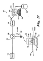
- Figure 1A is a diagram of one embodiment of a scanhead system.
- Figure 1B is a block diagram illustrating the ultrasound imaging system of Figure 1A .
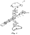
- Figure 2 is a perspective view of a scanhead of the system of Figure 1 .
- Figure 3A is a side vide of the scanhead of Figure 2 .
- Figure 3B is a top view of the scanhead of Figure 2 .
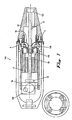
- Figure 4 is section A-A view of the scanhead of Figure 3B .
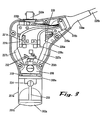
- Figure 5 is a detailed schematic view illustrating the scan head of Figures 3A, 3B and 4 .
- Figure 6 provides further details of the scanhead of Figure 4 .
- Figure 7 provides further details of the scanhead of Figure 3A .
- Figure 8 demonstrates alternative motions of the pivot tube 6.
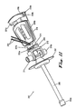
- Figure 9 is a diagram of another embodiment of a scanhead of the system of Figure 1A .
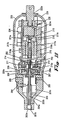
- Figure 10 is a longitudinal cross section of the scanhead of Figure 9 .
- Figure 11 is a perspective view of an armature assembly in the scanhead of Figure 9 .
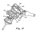
- Figure 12 is a perspective view of a portion of the scanhead of Figure 9 .
- Figure 13 is an exploded view of a release assembly of the scanhead of Figure 9 .
- Figure 14 is an assembled view of the quick release assembly of Figure 13 .
- Figure 15 is a perspective view of a seal of the scanhead of Figure 9 .
- Figure 16 is a perspective view of the scanhead of Figure 9 in a testing configuration.
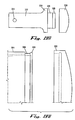
- Figure 17A is a perspective view of a nosepiece for the scanhead of Figure 9 .
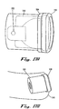
- Figure 17B is a perspective view of the nosepiece of Figure 17 shown with an optional shroud.
- Figure 18 is another view of the nosepiece of Figure 17 in a separated position.
- Figure 19A is side view of Figure 17 .
- Figure 19B is a detail view of Figure 19A .
- Figure 20 is a cross section of Figure 17 .
- Figure 21 is a cutaway of Figure 17 .
- Figure 22 is an end view of nosepiece of Figure 17 .
- Figure 23 is an end view of acoustic window of Figure 17 .
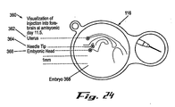
- Figure 24 is a screen shot depicting an image on the display.
- Figure 25 is a flow chart illustrating the operation of one aspect of the high-frequency, high frame-rate ultrasound imaging system.
- an ultrasound scanning system 100 has an electronics circuit 102 for transmitting and receiving a series of ultrasound pulses 104 to and from a probe or scanhead 106.
- the scanhead 106 can be situated on a subject 108 to record image data 110 of a scan plane 112, representing a cross section of a target 114 for display on a display 116.
- the target 114 may be, for example, the organ of a small animal, such as a mouse, a rat or another research subject. Examples of organs that can be imaged include, but are not limited to, a lung, a heart, a brain, a kidney, a liver and blood flowing within the subject. Further, the ultrasound imaging system can be used to image a neo-plastic condition.
- the circuit 102 has a transmit subsystem 118 for generating the pulses 104 and a receive subsystem 120 for receiving the corresponding echo pulses 104, which are directed to a computer 122 for processing and eventual display as the image scan data 110.
- the scanhead 106 is coupled at 126 to the circuit 102.
- the scanhead 106 has a transducer assembly 124, with a membrane 125, which is coupled to a position encoder 128 in conjunction with a torque motor 130.
- the encoder 128 and motor 130 monitor the position of the transducer assembly 124 within the scanhead 106.
- the corresponding position data 132 is transmitted with the pulses 104, representing the image data 110, to the computer 122.
- the scanhead 106 can be used as an encapsulated real-time probe for recording and displaying image data 110 obtained in real-time at high frequencies, such as but not limited to greater than 20 MHz and including 25 MHz, 30 MHz, 35 MHz, 40 MHz, 45 MHz, 50 MHz, 55 MHz. 60 MHz and higher. Further, transducer operating frequencies significantly greater than those mentioned above are also contemplated.
- the system 100 also includes a system processor 134.
- the processor 134 is coupled to the display or monitor 116 and to a human-machine interface 136, such as a keyboard, mouse, or other suitable device. If the monitor 116 is touch sensitive, then the monitor 116 can be employed as the input element for the human-machine interface 136.
- a computer readable storage medium 138 is coupled to the processor 134 for providing instructions to the processor 134 to instruct and/or configure the operation of the monitor 116 for recording and displaying the data 110, 132 on the monitor 116.
- the computer readable medium 138 can include hardware and/or software such as, by way of example only, magnetic disks, magnetic tape, optically readable medium such as CD ROM's, and semi-conductor memory such as PCMCIA cards.
- the medium 138 may take the form of a portable item such as a small disk, floppy diskette, cassette, or it may take the form of a relatively large or immobile item such as hard disk drive, solid state memory card, or RAM coupled to the processor 134. It should be noted that the above listed example mediums 138 can be used either alone or in combination.
- Figure 1B is a block diagram illustrating the ultrasound imaging system 100 of Figure 1A .
- the system 100 operates on a subject 114.
- the ultrasound probe 106 can be placed in proximity to the subject 114 to obtain image information.
- the ultrasound system 131 includes a control subsystem 127, a scan converter 129, the transmit subsystem 118, the receive subsystem 120 and the user input device 136.
- the processor 134 is coupled to the control subsystem 127 and the display 116 is coupled to the processor 134.
- a memory 121 is coupled to the processor 134.
- the memory 121 can be any type of computer memory, and is typically referred to as random access memory "RAM,” in which the software 123 of the high-frequency, high frame-rate ultrasound imaging system executes.
- the high-frequency, high frame-rate ultrasound imaging system can be implemented using a combination of hardware and software.
- the hardware implementation of the high frequency, high frame-rate ultrasound imaging system can include any or a combination of the following technologies, which are all well known in the art: discrete electronic components, a discrete logic circuit(s) having logic gates for implementing logic functions upon data signals, an application specific integrated circuit having appropriate logic gates, a programmable gate array(s) (PGA), a field programmable gate array (FPGA), etc.
- the software for the high frequency, high frame-rate ultrasound imaging system comprises an ordered listing of executable instructions for implementing logical functions, and can be embodied in any computer-readable medium for use by or in connection with an instruction execution system, apparatus, or device, such as a computer-based system, processor-containing system, or other system that can fetch the instructions from the instruction execution system, apparatus, or device and execute the instructions.
- a "computer-readable medium” can be any means that can contain, store, communicate, propagate, or transport the program for use by or in connection with the instruction execution system, apparatus, or device.
- the computer readable medium can be, for example but not limited to, an electronic, magnetic, optical, electromagnetic, infrared, or semiconductor system, apparatus, device, or propagation medium.
- the computer-readable medium could even be paper or another suitable medium upon which the program is printed, as the program can be electronically captured, via for instance optical scanning of the paper or other medium, then compiled, interpreted or otherwise processed in a suitable manner if necessary, and then stored in a computer memory.
- the memory 121 also includes the image data obtained by the ultrasound system 100.
- a computer readable storage medium 138 is coupled to the processor for providing instructions to the processor to instruct and/or configure processor to perform steps or algorithms related to the operation of the ultrasound system 131, as further explained below.
- the computer readable medium can include hardware and/or software such as, by way of example only, magnetic disks, magnetic tape, optically readable medium such as CD ROM's, and semiconductor memory such as PCMCIA cards.
- the medium may take the form of a portable item such as a small disk, floppy diskette, cassette, or it may take the form of a relatively large or immobile item such as hard disk drive, solid state memory card, or RAM provided in the support system. It should be noted that the above listed example mediums can be used either alone or in combination.
- the ultrasound system 131 includes a control subsystem 127 to direct operation of various components of the ultrasound system 131.
- the control subsystem 127 and related components may be provided as software for instructing a general purpose processor or as specialized electronics in a hardware implementation.
- the ultrasound system 131 includes a scan converter 129 for converting the electrical signals generated by the received ultrasound echoes to data that can be manipulated by the processor 134 and that can be rendered into an image on the display 116.
- the control subsystem 127 is connected to a transmit subsystem 118 to provide an ultrasound transmit signal to the ultrasound probe 106.
- the ultrasound probe 106 in turn provides an ultrasound receive signal to a receive subsystem 120.
- the receive subsystem 120 also provides signals representative of the received signals to the scan converter 129.
- the receive subsystem 120 is also connected to the control subsystem 127.
- the scan converter 32 is directed by the control subsystem 127 to operate on the received data to render an image for display using the image data 110.
- the ultrasound system 131 transmits and receives ultrasound data through the ultrasound probe 106, provides an interface to a user to control the operational parameters of the imaging system 100, and processes data appropriate to formulate still and moving images that represent anatomy and/or physiology. Images are presented to the user through the interface display 116.
- the human-machine interface 136 of the ultrasound system 131 takes input from the user, and translated such input to control the operation of the ultrasound probe 106.
- the human-machine interface 136 also presents processed images and data to the user through the display 116.
- a frame 140 of the scanhead 106 consists of two side plates 1a and 1b, which are attached to a position encoder 128 at a proximal end and to a pivot frame 3 at a distal end.
- the position encoder 128 may be, for example, an optical encoder such as a Renishaw RGB25.
- a nosepiece 20 can be releasably attached to the distal end of the scanhead 106.
- the side plates 1a and 1b provide a housing to allow for both hand held scanning and fixtured scanning with the scanhead 106.
- the housing provides a strain relieved entry/exit point for cables 142 to and from the scanhead 106.
- the housing may include an RF shielding component.
- a pair of ball bearings 4 are positioned in the pivot frame 3 to locate a rotor assembly 5, which allows the transducer assembly 124 to pivot freely back and forth through an angle of approximately 20 degrees.
- the rotor assembly 5 comprises a pivot tube 6 to which is connected a yoke 7. Screws through the pivot bearings 4 secure them to the yoke 7.
- a transducer 8 of the assembly 124 is connected to the distal end of the pivot tube 6, and its' coaxial signal cable 8a extends through the pivot tube 6 and out through a slot 6a, and is affixed to a circuit board 23 of the circuit 102 (see Figure 1A ).
- a lightweight yet stiff paddle 9 supports a rotor coil 10a and 10b, an encoder code track 12 and a Hall sensor magnet 13.
- a flexible coax cable 14 leads from the rotor assembly 5 from the side opposite the transducer coax 8a. Both of these are arranged to flex freely without binding or touching other structures as the transducer assembly 124 oscillates back and forth within the scanhead 106.
- Overall is fitted a plastic housing 31 and 31a.
- a mount nut 32 is secured between the two housing halves 31, 31a on assembly.
- the mount nut 32 has a threaded hole by which the scanhead 106 can be attached to a support arm (not shown), if desired.
- the nosepiece 20 is filled with an acoustic coupling fluid 15.
- the distal end of the scanhead 106 is sealed by the acoustic window 125, which comprises acoustically transparent plastic film and which will be described in further detail below.
- An o-ring 17 creates a seal between the nosepiece 20 and the nose 18 of the pivot frame 3.
- a rubber seal diaphragm 19 is located between the nose 18 and the pivot frame 3 making a fluid tight seal.
- a fluid tight seal is created between the seal diaphragm and the pivot tube 6 because a hole for the pivot tube 6 in the seal diaphragm 19 is smaller than the pivot tube, creating a tight seal when the seal diaphragm 19 is placed over the pivot tube 6 during assembly.
- the seal diaphragm 19 flexes to allow the pivot tube 6 to oscillate back and forth while maintaining the fluid seal there-between.
- a locking plate 34 comprising, for example, a bayonet-type locking mechanism is located on the back of the nosepiece 20.
- a twist of approximately 10 degrees in one direction causes the shank of screws 34a to travel in short curved slots in the locking plate 34, trapping the heads of screws 34a as shown and locking the nosepiece 20 to the scanhead pivot frame 3. It is noted that the nosepiece 20 can be removed by simply reversing this action.
- a fill port 35 can be used to initially fill a hollow cavity 15 in nosepiece 20 with acoustic fluid, and to periodically access the cavity 15 to remove any bubbles that may appear.
- the transducer assembly 124 is attached to the distal end of the pivot tube 6, creating a fluid tight seal.
- the distal face of the transducer 8 remains a fixed distance (such as, but not limited to, between 0.5mm to 1mm) from the acoustic window 125.
- the coaxial electrical cable 8a carrying signals to and from the transducer 8, leads down the center of the pivot tube 6 and emerges through the slot 6a near the pivot axis, thus minimizing motion of the coax cable 8a
- a slack length of coax cable 8a absorbs relative motion during operation, situated between the slot 6a and its termination point at the proximal end, i.e.
- the small printed wiring board (PWB) 23 the small printed wiring board (PWB) 23.
- the coax cable 8a and the coax cable 14 are constricted to have a long flex life.
- the cables 8a and 14 may be constructed using a small diameter (approx. 1 mm), and fine conductors, thereby enhancing flexibility.
- the PWB 23 contains a pro-amplifier for signals coming from the transducer 8, and acts as a termination point for the signal, power and ground wires from the two Hall sensors 13.
- the PWB 23 also receives wires 21 entering the scanhead 106 through a cable cap 33 and an encoder cable 25a.
- an encoder code track 12 and the Hall sensor actuating magnets 13 are all bonded to the proximal end of the pivot tube 6.
- An intermediate support structure 27 can be made of rigid polyethylene foam sandwiched between, for example, thin (0.1mm) epoxy-glass board, forming a lightweight but rigid core to support the rotor windings 24 and the encoder code track 12, in particular.
- the backing iron plates 2 and 2a are attached on the inside face of the side plates 1a and 1b.
- Field magnets 28 and 28a are bonded to the backing iron plates 2 and 2a, respectively.
- the field magnets 28 and 28a are magnetized through their thin direction, normal to their facing sides.
- Each magnet 28, 28a has four poles; half of each face is a north pole and the other half is a south pole.
- the rotor assembly 5 moves back and forth in the gap between the two magnets 28, 28a.
- the south pole of magnet 28 faces the north pole across the gap of magnet 28a.
- the north pole of magnet 28 faces the south pole of magnet 28a.
- a portion 10a of the rotor coil 10 is constrained to oscillate within the confines of one pole gap, and another portion 10b oscillates in the other gap.
- the torque motor 130 rotates the tube or support arm 6 on the pivot back and forth through a limited angle, i.e. approximately 10-14 degrees.
- the transducer assembly 124 is connected to one end of the support arm 6, and the position encoder code track 12 is connected to the other end.
- the transducer 8 of the assembly 124 is aimed such that a focused ultrasound beam can be directed along the longitudinal axis of the pivot tube 6, away from the pivot point.
- the case and nosepiece 20 mound the torque motor 130, position encoder 128 and transducer 8 such that the transducer 8 is located within the nosepiece section 20.
- the nosepiece section 20 can be filled with water (or another medium suitable for conducting ultrasound): the torque motor 130 and position encoder 128 are dry due to the seal 19.
- the pivot tube 6 passes through the flexible seal 19, enabling the pivot tube 6 to move back and forth.
- the acoustic window 125 can be located at the end of the nosepiece 20.
- the position encoder 128 used in the scanhead 106 is, for example, an optical encoder capable of 1 micron ( ⁇ m) resolution.
- the position encoder 128 works in conjunction with a reticulated tape strip referred to herein as the encoder code track 12.
- the position encoder 128 makes use of an optical sensor to count the passage of reticules on the encoder code track 12 as they pass a sensor associated with the position encoder 128.
- the sensor can sense both direction of travel of the proximal end 150 of the pivot tube 6, and track the position of the travel of the distal end 152 of the pivot tube 6 to within 1 micron.
- the encoder code track 12 can be connected to the rear of the pivot tube 6 of the scanhead 106 at a known radial distance from the pivot point 154 of the pivot tube 6.
- the encoder code track 12 is attached to a precise surface having a radius such that the encoder code track 12 is everywhere tangential to a chord traced out by the pivot tube 6.
- the encoder code track 12 passes back and forth under the optical sensor in the position encoder 128. The result is the digitization of the position of the distal end 152 of the pivot tube 6 at the radius at which the encoder code track 12 is fixed.
- the position information can be used to determine the location of the transducer 8 located the same radial distance from the pivot point on the other end of the pivot tube 6. Dissimilar distances of the proximal end 150 and distal end 152 measured from the pivot point 154 can also be used, if desired.
- the optical coupling between the position encoder 128 and the proximal end 150 of the pivot tube 6 reduces the transmission of electronic noise generated by the position encoder 128 and the circuit 102 from the transducer 8.
- the transducer 8 can be a high-frequency single-element focused piezoelectric ultrasonic transducer, with a frequency greater than 30 MHz and can be around 40 MHz.
- the transducer 8 receives the RF electrical pulse 104 as input and produces an ultrasonic acoustic pulse 104 as output during the transmit phase of operation of the circuit 102 (see Figure 1A and Figure 1B ).
- the reverse process is performed during the receive phase such that the input to the transducer 8 is an ultrasonic acoustic pulse 104 which is converted by the transducer 8 into a radio frequency electrical signal, represented by data 110.
- the transducer 8 used in the scanhead 106 can be a broadband transducer 8 fabricated in such a way to ensure a good acoustic match to the acoustic medium in the cavity 15.
- the pivot tube 6 can be an ultra light weight stainless steel tube fixed by the bearing assembly 4 in such a way that it pivots about its midpoint 154.
- the transducer 8 is connected to one end of the pivot tube 6, while the encoder code track 12 is connected to the other end of the pivot tube 6.
- the pivot tube 6 houses the coils of the torque motor 130 between the bearing assembly 4 and the encoder code track 12, thus forming an integral part of the torque motor 130.
- the pivot tube 6 also acts as a conduit for the transducer coax cable 8a.
- the pivot axis bearing 4 comprises a pair of ball bearings and an off axis, or offset, clamp 146, which holds the pivot tube 6.
- the offset clamp 146 allows the pivot point of the pivot tube 6 to remain accessible for the routing of cables 8a and mechanical attachment to and from the pivot tube 6.
- the bearing 4 can be fabricated with precise bearings and accurately machined components to ensure highly repeatable one axis rotation about the pivot point 154.
- the offset clamp 146 is connected to the pivot tube 6 at one end and is rotatably attached to the pivot point 154 at the other end through pins 148.
- the flexible seal 19 can be attached to the midpoint of the pivot tube 6, and the rear of the nose piece 20 bayonet quick release assembly comprising the locking plate 34 and the two screws 34a.
- the seal 19 can be made of an elastomer membrane that is fastened so that it forms a fluid tight seal between the pivot tube 6 and the nosepiece 20.
- the seal 19 separates the fluid filled nosepiece 20 from the remainder of the housing which remains dry.
- Two Hall sensors 13 are placed in the housing of the scanhead 106 so that they sense the travel of the pivot tube 6 past their respective sensors 13.
- the sensors 13 are placed so that they produce a signal at the maximum safe travel of the torque motor 130.
- the limit switches 13 are also placed symmetrically about the pivot point 154 so that they can be used to home the system to a zero deflection, homed, or normal position.
- the hollow cavity 15 in the nose piece 20 can be fluid filled.
- the nosepiece 20 provides a mounting structure to which the acoustic window 125 can be attached.
- the nosepiece 20 features a drain/fill screw as a fill port 35 through which fluid may be added or removed from the cavity 15.
- the nosepiece 20 can contain part of a bayonet style quick release assembly allowing it to be removed and changed quickly without the need for tools, while ensuring a fluid tight seal.
- the acoustic window 125 comprises a thin membrane of a material well acoustically matched to the fluid in the cavity 15.
- the acoustic window 125 can be held in a position so that it remains close to and normal to the face of the transducer 8 over the full extent of transducer travel (approximately 0.5mm to 1mm, for example). Material from which to form the acoustic window were initially selected or rejected based on known bulk acoustic properties.
- the membrane can be chosen to exhibit acoustic impedance in the range of 1.3 to 1.7 megaRayles (MRayles), such as 1.5 megarayles.
- Material from which the acoustic window can be fabricated include polyester films ranging in thickness from about 0.9 um to 4.5 ⁇ m, polytetrafluoroethylene (PTFE) in thicknesses of 5 ⁇ m.
- PTFE polytetrafluoroethylene
- LDPE low density polyethylene
- polycarbonate in a thickness of 2 ⁇ m
- polypropylene in a thickness of 4 ⁇ m latex elastomer in a thickness of 60 ⁇ m
- silicone elastomer in a thickness of 25 ⁇ m were tested in a variety of configurations including varying the angle of incidence of the ultrasound beam to the membrane forming the acoustic window 125 from 90 degrees to 110 degrees.
- These materials and thicknesses were used with transducer frequencies of 30-40 MHz. Thinner membranes could be used as the frequency increases.
- the encapsulated coupling fluid can be varied to improve the acoustic march with the membrane of the acoustic window 125.
- ethylene glycol, triethylene glycol, water, light paraffin oil and various aqueous solutions of glycols can be used.
- Water as a coupling fluid and a 25 ⁇ m thick membrane of LDPE can be used as the membrane for the acoustic window 125.
- an acoustic window 125 formed of 5 ⁇ m thick or 15 ⁇ m thick PTFE are provided.
- thin silicone elastomer can also be provided for the membrane forming the acoustic window 125.
- the acoustic window 125 maintains a fluid tight seal between the nosepiece 20 and the outer environment of the scanhead 106. Accordingly, the acoustic window 125 used with a high frequency ultrasound transducer 8 is thin, and can be composed of a material that has an acoustic impendance very close to that of the fluid in the cavity 15.
- the electronics circuit 102 provides both a low noise RF preamplifier and a proprietary high fidelity protection circuit to the scanhead 106.
- the electronics circuit 102 protects sensitive receive instruments in the receive subsystem 120 from the high energy pulse 104 used to drive the transducer 8.
- the low-noise preamplifier boosts the signal of the transducer 8 with minimal distortion.
- the Hall sensor 13 trigger one of two Hall sensor magnets 26 and 26a, one at each end of travel fixed to side plates 1a and 1b.
- the control subsystem 127 responds by reversing the polarity of the voltage supplied to the rotor, driving the rotor assembly 5 in the opposite direction until the other Hall sensor 13 is triggered. All this time, the position encoder 128 reads the encoder code track 12 and determines the position of the transducer 8 relative to the two end-of-travel events indicated by the Hall sensors 13. The control system can now drive the transducer 8 back and forth over whatever path and velocity profile is programmed into the controller, using the signals from the position encoder 128 for positional feedback.
- M-mode and Doppler are two other modes of operation for which the scanhead 106 is suited.
- the rotor assembly 5 is electrically driven to a fixed position, usually under operator control using a joystick associated with the human-machine interface 136 for input commands.
- the operator (not shown) can view an image frozen in time on the display 116, or a series of images, which are periodically updated, and manipulate the direction in which the transducer 8 is pointing.
- An electronic representation 144 ( Figure 1A ) of the direction in which the transducer 8 is pointing can be displayed over the ultrasound image on the display 116, and can be used for visual feedback.
- the propagation path of ultrasound should be entirely within water or another fluid which has acoustic impedance very close to that of tissue.
- An air gap, or a material located in the path which creates an acoustic impedance mismatch can cause unwanted reflections, which appear as artifacts in the image on the display 116.
- a coupling gel which has acoustic properties very similar to water, can be used between the scanhead 106 and the tissue being imaged.
- the torque motor 130 in conjunction with the position encoder 29 and encoder code track 12 run in a closed loop. They act as a servo-motor and are controlled by a motor control system associated with the processor 134 so that the pivot tube 6, which can be fixed in place by the pivot bearings 4, rotates back and forth about the pivot axis 154 in a controlled manner.
- the transducer 8 can be fixed to the end of the pivot tube 6 opposite the encoder code track 12.
- the pivot tube 6 moves the transducer 8, which is scanned back and forth within the fluid filled nosepiece 20.
- the location of the transducer 8 is known at all times to within 1 micron.
- the transducer 8 transmits and receives ultrasonic information which is received and amplified via the circuit 102, and then sent to the processor 134.
- this process can be accomplished at 15 Hz allowing for the production of real-time images for display of the image data 110 on the display 116.
- Operating the transducer 8 at a frequency of 15 Hz equates to a frame rate of 30 frames per second, as two sweeps of the transducer 8 through its range of motion equates to one Hz.
- the oscillating frequency of the transducer 8 may be increased to increase the frame rate.
- the ultrasound system 131 provides images having a spatial resolution of less than 30 microns. For example, at a frequency of approximately 25 MHz, the spatial resolution is approximately 75-100 microns.
- the spatial resolution improves.
- spatial resolution may exceed 30 microns.
- the high operating frequency of the transducer and the precise mechanical positioning of the transducer with an accuracy of approximately 1 ⁇ m allow the ultrasound system 131 to provide real-time ultrasound images having spatial resolution in excess of 30 ⁇ m
- the scanhead 106 can be designed for use either by hand or on a fixture.
- the scanhead 106 can also be used as an immersion style scanner in a water bath or it can be coupled with gel to the tissue to be scanned. In these situations, the membrane of the acoustic window 125 may be removed.
- the scanhead 106 is an electrically driven handheld imaging device that oscillates the ultrasound transducer 8 in a fan-shaped arc while maintaining good acoustic coupling between the transducer 8 and the subject 108 being imaged.
- the position encoder 128 delivers real-time position information to the controlling system processor 134. As the transducer 8 moves, signals from the position encoder 128 trigger transmit pulses 104 and communicate to the system processor 134 the position at which the resulting data stream 110 collected between those pulses 104 should be displayed in the electronic image that comprises the visual output on the display 116.
- the scanhead 106 can move the transducer 8 continuously back and forth within a fluid environment over a distance of approximately 10 mm in a controlled manner at a rate up to and exceeding 15 Hz, which corresponds to a frame rate of 30 frames per second.
- the position encoder 128 in the scanhead 106 records the position of the transducer 8 in real time with an accuracy of 1 ⁇ m, and can position the transducer 8 at an arbitrary location within the scan region to an accuracy of 1 ⁇ m
- the scanhead 106 includes the acoustic window 125 through which the ultrasound energy can be directed towards the subject 108 being imaged.
- the acoustic window 125 allows the transmission of high frequency ultrasound with minimum attenuation and/or reflection.
- the scanhead 106 can be sufficiently compact to be easily hand held, and can achieve positioning accuracy to 1 ⁇ m with a 15 Hz mechanical pivoting scanning and positioning system.
- the acoustic window 125 can be compatible with the transmission of high frequency ultrasound energy, at frequencies in excess of 60 MHz.
- the scanhead 106 can have image resolution smaller than 30 ⁇ m with an imaged region of approximately 8 mm by 8mm for the scan plane 112 (see Figure 1A ).
- the scanhead 106 uses a single moving part, the pivot tube 6, and a limited angle torque motor 130 of the moving coil type.
- the torque motor 130 produces large torque force with little current draw because the non-moving field magnets 28 and 28a are relatively large and are made of a high energy product material, such as, but not limited to, neodymium iron- boron, which maintains a very high B field across the rotor windings 24.
- Another benefit of using a moving coil type motor is that the rotor mass, and rotational inertia, can be minimized, which helps to reduce power consumption and vibration. Small structures within the subject 108 being imaged at 40 MHz or greater are often associated with rapid movement. Therefore, such a design allows for operating speeds of 30 Hz or higher, corresponding to 60 frames per second.
- the flex seal 19 isolates the fluid in the cavity 15 from the elements on the opposite side of the flex seal 19.
- the flex seal 19 can be located near the pivot point 154 of the rotor assembly 5 by using the offset clamp 146 to allow the pivot bearings 4 to straddle the point where the flex seal 19 can be attached to the pivot tube 6, which helps to minimize the stresses on the flex seal 19.
- the attachment of the flex seal 19 can be accomplished by a simple friction fit between the hole in the flex seal 19 and the pivot tube 6.
- the flex seal 19 can be made of a polyurethane elastomer possessing high fatigue life.
- the portion of the pivot tube 6 immersed in the acoustic fluid, and the transducer 8, which can be wholly immersed, can be designed to be neutrally buoyant. When in motion, neutral buoyancy helps cancel vibration that could otherwise be a consequence of the motion of the transducer 8 and pivot tube 6.
- the entire oscillating mechanisnn on either side of the pivot point 154 can be so adjusted to be neutrally buoyant and operates entirely immersed in the acoustic fluid. This can help to eliminate virtually all vibration that would otherwise be transmitted to the operator and the subject 108.
- the nosepiece 20 can be easily removed and replaced by the operator.
- the simplified removal and replacement of the nosepiece 20 facilitates the replacement of a damaged acoustic window 125 or contaminated acoustic fluid.
- the fill port can be provided on the side of the nosepiece 20 to initially fill the cavity 15 with acoustic fluid when the nosepiece 20 is installed and to displace any bubbles with additional fluid should they develop with use.
- a simple bayonet type twist lock can be used to secure the nosepiece 20 to the body of the scanhead 106. If the nosepiece 20 should be sterile, as it might for some uses, it can be disposable.
- An integral part of such a replaceable nosepiece 20 can be a sterile drape or sheath, made of thin plastic, heat sealed or otherwise attached to the base of the nosepiece 20, which could be an injection molded plastic part.
- the scanhead 106 can also be operated, if desired, with the acoustic window 125 removed.
- the scanhead 106 can be designed for reciprocal motion of the arm 6 with an appropriate flex seal 19, if desired.
- the flex seal 19 could be of an accordion design, if desired.
- the scanhead 206 includes a chassis 215 capable of supporting all of the components of the scanhead 206.
- a circuit board 224 is integrated into the scan head 206.
- the chassis 215 supports a strain relief clamp base 225a, a strain relief clamp 225b and a strain relief 226a for securely holding a cable assembly 226b at a proximal end of the chassis 215.
- the cable assembly 226b connects to electrical convectors 229a, 229b on the circuit board 224.
- the circuit board 224 includes a motor control element, position monitoring circuit and communicates RF signals between the transducer and the processing elements in the ultrasound system 131 (see Figure 1B ).
- the chassis 215 supports a pivot frame 208 that in turn supports a yoke 212 attached to armature 240 ( Figure 11 ) at a distal end of the chassis 215.
- the armature 240 is described in further detail below with reference to Figure 11 .
- a bayonet style lock plate 205a interfaces with a fixture on a nose 205 that is mounted to the pivot frame 208.
- the lock plate 205a is attached to a removable nosepiece 201a.
- the nosepiece 201a has an acoustic window including a membrane 201b mounted at one end thereof.
- the nosepiece 201a surrounds a coupling fluid cavity 201c.
- the assembly comprising the nosepiece 201 a and lock plate 205a is mounted onto the scan head 206 via the bayonet style lock system.
- the coupling fluid cavity 201c surrounds a transducer 202a, which is attached to the support arm 203.
- the transducer 202a is connected to a transducer coaxial cable 202b, which is connected at the opposite end to the circuit board 224.
- the nosepiece 201a includes a fill port to fill the coupling fluid cavity 201c with a coupling fluid.
- the fill port is sealed by a fill port screw 204:
- a molded rubber seal 207 is mounted on the support arm 203 and disposed between the fluid cavity 201c and a pivot frame 208.
- a bearing assembly including a bearing preload screw 209, precision radial ball bearings 208a, and a fixing screw 210a affixes the armature assembly 240, to the pivot frame 208, with low radial drag and virtually no radial or axial play.
- a yoke 212 is provided straddling the support arm 203 and fixed to the rotor 218 with rotor adhesive pins 214.
- a partial assembly 250 of the scan head 206 shown in Figure 12 includes a rear backing iron 216a, a pair of backing iron posts 227a and 227b, rear field magnet 217a.
- An optical encoder code track 219 is attached to one end of the rotor 218 such that it is at all points tangent to the motion of the torque motor.
- An optical encoder read head 220 is affixed to an encoder adjustment slide 223a as shown in Figure 12 .
- the encoder adjustment slide 223a is fitted to the chassis 215 so that it can slide allowing adjustment of the optical read head 220 with respect to the encoder code track 219, which is fixed to the armature 240.
- the movement is precise and controlled, and when the encoder read head 220 is in the optimal position such that maximum signal strength is obtained at the encoder read head 220, the read head adjustment slide 223a is locked in place with read head locking screws 223c. Because the optical encoder is focused, it can be positioned at a known distance from the reflective encoder code track 219. This distance corresponds to a maximum encoder signal. A helical spring 223d coupled to the read head adjustment screw 223b helps prevent backlash. The optical read head 220 combined with the encoder code track 219 allows the position of the armature 240 to be recorded with an accuracy of 1 ⁇ m.
- a pair of optical limit switches 221a are provided on the circuit board 224 for determining the absolute position of the armature 240 with respect to the chassis 215, and to protect against over travel of the armature 240.
- a reflective surface 221b attached to the rotor 218 reflects signals from the optical limit switch 221a.
- the chassis 215 includes a quick release hard mount jack222a. This mechanism is part of a quick release assembly, which is described in greater detail below with reference to Figures 13 and 14 .
- a case comprising a case top 233, a case bottom 234 and a case gasket 228 provides a fluid-tight seal around the internal components of the scan head 206.
- the case top 233 and case bottom 234 as well as the case gasket 228 are coated with an electrically conductive coating 251 to improve RF shielding.
- the armature 240 can be fabricated from precision machined components, which facilitates manufacturability, reduces cost, and improves performance compared to the composite construction used in the embodiment referred to above.
- the support arm 203 is removable and can be mounted via the support arm mount 213 and two shoulder bolts 231a and 231b, which locate into precision holes in the yoke 212 and the rotor 218. It will be recognized therefore that a damaged transducer 202a and/or molded seal 207 may be replaced without replacing the entire armature 240.
- the encoder code track 219 is made from a spring steel substrate.
- the encoder code track 219 can be installed using a technique which avoids prebending of the encoder code track 219. Prebending may damage the encoder code track 219.
- Two encoder code track retainers 230a hold the encoder code track 219 at each end, forcing the spring steel to take the exact curvature of the rotor 218.
- the encoder track retainers 230a are fixed in place using screws 230b.
- a light string may be tied around screws 230b and adhered, using, for example, a glue, to the ends of the encoder code track 219
- the scanhead 206 of this embodiment provides a sweep angle greater than 22 degrees included.
- the sweep angle refers to the motion of the transducer 202a defined by the Hall sensor 13, the two Hall sensor magnets 26 and 26a, and the limit switches 221a.
- the length of the support arm 203 may be changed, during manufacture or after, such as during field service, to accommodate different imaging requirements.
- the support arm 203 can be a length such that the transducer 202a is approximately 20 percent farther from the pivot point 154 than the encoder code track 219 (see Figure 9 ). This configuration provides a scan width of over 15mm measured at the transducer 202a.
- the scan head 206 in this embodiment is assembled on the rigid chassis 215.
- the scan head 206 can be assembled to complete functionality on the chassis 215 so that testing can be performed without the case 233, 234 in place.
- the design of the chassis 215 therefore allows verification of wire routing and strain relief, electrical inspection, timing of the optical encoder read head 220, and function verification of the limit switches 221a.
- the quick release mechanism uses a spring loaded bayonet lock to quickly mount and remove the scanhead 206.
- the quick release hard mount plug 222b includes a locating pin 222c at the end proximal to the quick release hard mount jack 222a.
- the hard mount plug 222b includes a quick release upper feature 222d adjacent to the locating pin 222c, and a helical spring 222f adjacent to the locating pin 222c.
- the locating pin 222c allows the scanhead 106 to be mounted and remounted in precise 90 degree increments.
- a retaining ring 222e bears against the hard mount plug 222b when attached to the hard mount jack 222a as seen in Figure 14 .
- the nose 205 includes gasket bosses 206b, which prevent damage to the molded seal 207 ( Figure 11 ) when clamping the molded seal 207 between the nose 205 and the pivot frame 208.
- the seal 207 can be made from a soft, flexible elastomer.
- the molded shape provides a centered rest position and eliminates stretch mode deformation of the seal 207 during operation.
- a flat seal undergoes both bending and stretching during operation, resulting in two distinct loads on the motor, which can be difficult to compensate for.
- the molded seal 207 can be designed like a shifter boot on an automobile's gear shift. It undergoes only bending deformation, which results in a lower and more uniform load on the motor.
- the scanhead 206 includes an integral circuit board 224 that integrates motor control functions, position monitoring functions, and the transmission and reception of RF signals.
- the circuit board 224 houses the optical limit switches 221a.
- the circuit board 224 can be prefabricated and tested.
- the circuit board 224 allows the routing of the transducer coaxial cable 202b and the motor wires 232 to be made with a minimal drag on the motor by placing the connection points nearly over the pivot point.
- the case 233, 234 can be non-load bearing and can be a purely protective part of the scanhead 206. It serves to waterproof and keep the internal components of the scanhead 206 free of contamination.
- the case 233, 234 can be secured to the chassis 215 by screws.
- the two halves 233, 234 of the case may be glued, or otherwise adhered, together to make the scanhead 206 tamper and water resistant.
- the nosepiece 201a may include a disposable acoustic window. Referring to Figures 17A, 17B , 18 , 19A, 19B and 20-23 , the structure of the nosepiece 320 and acoustic window 330 are shown.
- the acoustic window 330 is similar to the acoustic window 125 described above.
- the nosepiece 320 includes a fill port 322 for receiving fluid.
- the nosepiece 320 has a shoulder 324 at the end proximal to the acoustic window 330 when attached.
- a recess 326 and a lip 328 are located adjacent the shoulder 324 for forming a snap fit with the acoustic window 330.
- Figure 17B shows the nosepiece 320 with an optional shroud 340 attached.
- the shroud 340 attaches to the acoustic window 330 to protect the nosepiece 320 and scanhead 206 from contamination by liquid or biological material.
- the acoustic window 330 includes a groove 332 with a shape complementary to the lip 328 in the nosepiece 320.
- the acoustic window 330 can be designed to overcome the specific challenges of encapsulating a high frequency high-resolution ultrasonic probe in a variety of demanding environments.
- the acoustic window 330 provides an inexpensive means for protecting the transducer and allowing imaging in a sterile environment without unduly compromising acoustic performance.
- the acoustic window 330 can be constructed from a molded plastic frame comprising a fluid tight mechanical snap-on attachment structure.
- the acoustic window 330 can be a molded, disposable element, which 'snaps' onto a permanent machined nosepiece, yielding the fluid filled encapsulated nose of the probe. Tools are not required to remove or attach the acoustic window to the nosepiece.
- the shape of the acoustic window permits attachment to the nosepiece of the transducer using a simple rolling motion.
- the acoustic window can be any shape depending upon the nosepiece to be covered.
- a thin film of a sonolucent material forms a membrane 352 that can be attached to the front face of a frame 350.
- the frame 350 and the membrane 352 comprise the acoustic window 330.
- the characteristics and thickness of the material forming the membrane of the acoustic window are chosen to suit the characteristics of the specific probe to be encapsulated.
- Sonolucent materials for example those disclosed in U.S. Patent Nos. 5,479,927 ; 5,983,123 ; and 6,574,499 , can be used to produce the membrane 352 of the acoustic window 330.
- the sonolucent material can be a polyester, a polycarbonate, an acrylic, a thermoplastic elastomer, or a silicone elastomer.
- Examples of sonolucent materials include, but are not limited to, Surlyn® ionomers, such as Surlyn® 8940, and Kapton®, available from E.I.
- the sonolucent material can be extruded to a certain thickness and heat welded to the frame 350 of the acoustic window 330 to form a fluid tight seal.
- the thickness of the membrane 352 will vary depending upon the sonolucent material selected.
- the membrane 352 has a thickness of less than or equal to 25 ⁇ m In another embodiment, the thickness of the membrane 352 can range from 1 ⁇ m to 25 ⁇ m.
- the technology used for sealing the membrane 352 to the frame 350 will vary depending on the sonolucent material selected. Examples of methods for sealing the membrane 352 to the frame 350 include, but are not limited to, adhesives, welding techniques (e.g., RF, ultrasonic, and thermal), and mechanical seals.
- the snap structure comprises a groove 332 in the frame 350.
- the nosepiece 320 to which the acoustic window 330 will attach incorporates a lip 328.
- the lip 328 can be slightly oversized negative with respect to the groove 332 in the frame 330.
- the acoustic window 330 can be pressed onto the nosepiece 320 so that a positive fit is obtained when fully in place due to the seal formed between the lip 328 and the groove 332. This fit is also fluid tight due to the interference type fit of the groove 332 and lip 328.
- the nosepiece Before fitting the acoustic window 330 onto the nosepiece 320, the nosepiece can be partially filled with a coupling fluid.
- coupling fluid examples include, but are not limited to, water, ethylene glycol, triethylene glycol, light paraffin oil and various aqueous solutions of glycols.
- a sheathed version of the acoustic window 330 includes a heat sealed sheath 340 of polyethylene film that can be designed to fit back over the probe and up the cable.
- the sheath can be formed as part of the disposable acoustic window 330, so that when sterilization is desired the entire window and sheath can be removed and discarded.
- the high-frequency, high frame-rate ultrasound imaging system may be used to image a syringe, catheter, or other invasive element inserted into a subject.
- Figure 24 is a screen shot depicting an image 360 on the display 116.
- the image includes an embryo 368.
- the embryo 368 includes a head 366 and a uterus 362.
- the ultrasound system 131 can be used to visualize and guide the needle 364 as it enters the uterus 362 of the embryo 368.
- Figure 25 is a flow chart 400 illustrating the operation of one aspect of the high-frequency, high frame-rate ultrasound imaging system.
- the blocks in the flow chart may be executed in the order shown, out of the order shown, or concurrently.
- the transducer 8 generates ultrasound energy at a frequency of at least 20 MHz.
- the ultrasound energy is transmitted by the transmit subsystem 118 into the subject 114 ( Figure 1 ).
- the receive subsystem 120 receives the returned ultrasound echo pulses 104 and communicates the received ultrasound to the control subsystem 127 for processing by the processor 134 and the scan converter 129.
- the received ultrasound is processed by the processor 134 and the scan converter 129, under the direction of the software 123, to generate an image on the display 116.
- the image has a frame rate of at least 15 frames per second (fps).
Description
- Scanheads that were developed in the late 1970's and early 1980's for imaging human tissue are still useful for many ultrasound imaging applications. A transducer located in the scanhead comprises discs of piezoelectric material, which when excited electrically vibrates at a frequency usually chosen to be between 2 and 10 MHz. At these frequencies, the vibrational energy of the transducer is directional and radiates from two faces of a thin circular disc in reasonably well-defined beams. In general, the energy radiating from the back of the transducer is absorbed by a suitable material while that from the front is coupled to the patient by a fluid capable of transmitting ultrasound energy with low loss characteristics. Emerging through a thin, low-loss cap, the energy is further coupled to the patient with a sonolucent gel applied to the patient's skin. Echoes resulting from the interaction of the ultrasound energy with body tissue traverse the same path in reverse, and when they strike the transducer generate an electrical signal whose strength is a function of the echogenicity of a target within the patient and the target's depth below the patient's skin. The location in depth is determined from the time interval between the transmit pulse and the received echo. With this information and the directional information delivered by a position encoder coupled to the transducer, the scanheads generate a gray-scale image of the tissue lying in a scan plane within the patient, which is refreshed and updated with every sweep of the transducer across the image plane. Two sweeps of the transducer comprises one operating cycle, referred to as 1 Hz, and equates to two frames per second.
- Two dimensional ultrasound images (also known as B-scans) are made up of a number of adjacent lines of ultrasound data called A-scans, which are acquired from the scanhead through successive sweeps of the transducer. The line of ultrasound data is acquired when a transducer transmits the ultrasound pulse into the tissue being studied and then receives the ultrasound signal reflected by the tissue along a beam axis of the transducer. The lines of ultrasound data are located within the same plane and are usually spaced at constant intervals. Each line of data is acquired with the ultrasound beam axis moved laterally within the plane by a known incremental distance. The ultrasound image may have a linear format, in which the lines are parallel to one another and equally spaced, or a sector format, in which the lines radiate from an apex with equal angles between them. To produce a linear format image, the transducer is moved laterally, without altering the angle between the transducer and the line along which it is moved. To produce a sector format image, the transducer is mounted to a fixture, which rotates about an apex, causing the transducer to move in an arc. As the transducer moves, the position within the scan plane is tracked so that an associated ultrasound system can display the ultrasound line data at the correct locations within the displayed image.
- Early clinical diagnostic ultrasound systems used wobbler scanheads to produce the sector format images. These systems used low frequency ultrasound, in the 2 to 5 MHz range. The wobbler scanheads usually consisted of the transducer located within a fluid filled chamber, a motor, a position encoder, and an acoustic window through which the ultrasound passed. The motor drive mechanism usually moved the transducer through an arc, resulting in a sector scan type image format while the position encoder kept track of the transducer position. The wall of the fluid filled chamber, which faced the tissue being imaged, acted as an acoustic window, which was usually made of a hard plastic material. This window allowed ultrasound to pass through with little attenuation. Further, in general, there is a reflected ultrasound wave which does not pass through the window. This wave can reverberate between the transducer and the window several times before dissipating. The reverb components, which strike the transducer, can cause an undesirable artifact in the ultrasound image. The magnitude of the reflected wave is determined by the acoustic impedance mismatch between the material used for the window and the fluid in the transducer chamber. The amount of attenuation is determined by the window material, which occurs as the ultrasound energy passes through the window. Both attenuation and reflections at the window are undesirable.
- In the 80's these mechanically scanned transducers began to be replaced by solid state devices which consist of a plurality of narrow piezoelectric elements which, when excited sequentially, can be used to build up an image. These "linear array" scanheads had been developed at the same time as the mechanical ones, but delivered poorer image quality. Further work, throughout the 80's and 90's resulted in the development of "phased array" scanheads, which have the ability to excite groups of elements in ways that allow electronic beam steering and focusing, which in general produce better images than any mechanical scanhead and at frame rates of 60 frames per second. Today, phased arrays are universally used for ultrasound imaging of human tissue. However, a typical phased array system using a transducer operating at five MHz might have a spatial resolution of 0.5mm.
- One disadvantage with higher operating frequencies is as the operating frequency increases, fabrication difficulties make it challenging to build a phased array type imaging system. As a result, current systems operating in the 30-40 MHz range typically use mechanically scanned single element transducers, in scanheads similar in operating principal to the mechanically scanned systems described above. However, high frequencies generally result in higher attenuation and thus the attenuation due to an acoustic window is increased significantly. Accordingly, current high frequency transducers use a non-encapsulated transducer, which is moved back and forth with a linear servo-motor and position encoder system. At higher frequencies (greater than 30 MHz), transducer encapsulation is impractical due to a breakdown of theoretical properties and characteristics of materials with higher frequencies.
- For high frequency transducers, since it is not encapsulated, the moving transducer is exposed. Acoustic coupling to the tissue being imaged is accomplished by creating a mound of ultrasound gel on the surface of the tissue, into which the moving transducer is lowered. Satisfactory imaging depends on the existence of a continuous layer of gel between the transducer and the tissue. If the transducer loses contact with the gel, or if an air bubble forms on the surface of the transducer, imaging will be compromised or even impossible. This type of imaging is restricted to relatively low frame rates, because a rapidly moving transducer will disrupt the gel layer and is more likely to lose contact. Further disadvantages of exposed transducers are that they can create a hazard to delicate tissue, and can also expose the transducer to possible damage from impact.
- A further disadvantage in mechanical ultrasound scanheads is the use of moving magnet motors. The attraction of the moving magnet type is that there is no need for flexible wires to deliver power to the drive coil because the drive coil is stationary and the permanent magnet is attached to the moving member or rotor. Furthermore, the magnet type motor is inefficient. The usual mechanical scanhead consumes up to three Watt of electrical power, which is converted into heat that must be dissipated through plastic walls of the scanhead housing. As the housing is generally a poor conductor of heat the internal temperature of the scanhead may rise, which in time can degrade materials, alter the acoustic properties of the device, and can even be uncomfortable to the subject. Another reason the magnet motor is inefficient is that in an effort to keep the oscillating mass low, the moving magnets are kept relatively small. To achieve a certain torque, motor currents are correspondingly high, which gives rise to a high I^2R loss. These losses increase roughly as the square of the scanning rate.
- In "High Frequency (20 MHZ) Ultrasonic Devices: Advantages and Applications" (BERSON M ET AL, EUROPEAN JOURNAL OF ULTRASOUND, ELSEVIER, vol. 10, 1999, pages 53-63) an ultrasonic scanning device is disclosed, comprising a scan head having a single transducer element oscillating around an axis of rotation, whereby the spatial position of the transducer along the reciprocating convex arcuate path is determined. The transducer is capable of generating ultrasound energy at a frequency of 20 megahertz.
- In "High-resolution real-time ultrasonic scanner" (BERSON M ET AL, ULTRASOUND IN MED. & BIOL., vol. 18, No. 5, 1992, pages 471-478), an ultrasonic scanning device, which comprises a single oscillating transducer and a processor for providing a frame rate of 15 frames per second in order to allow real-time imaging, is disclosed.
- In the invention, which is defined in claim 1, the high-frequency, high frame-rate ultrasound imaging system comprises a scan head having a transducer capable of generating ultrasound energy at a frequency of at least 20 megahertz (MHz), and a processor for receiving ultrasound energy and for generating an ultrasound image at a frame rate of at least 15 frames per second (fps).
- The high frequency, high frame-rate ultrasound imaging system can be better understood with reference to the following Figures. The components within the figures are not necessarily to scale, emphasis instead being placed upon clearly illustrating the principles of the high-frequency, high frame-rate ultrasound imaging system. Moreover, in the figures, like reference numerals designate corresponding parts throughout the different views.
-
Figure 1A is a diagram of one embodiment of a scanhead system. -
Figure 1B is a block diagram illustrating the ultrasound imaging system ofFigure 1A . -
Figure 2 is a perspective view of a scanhead of the system ofFigure 1 . -
Figure 3A is a side vide of the scanhead ofFigure 2 . -
Figure 3B is a top view of the scanhead ofFigure 2 . -
Figure 4 is section A-A view of the scanhead ofFigure 3B . -
Figure 5 is a detailed schematic view illustrating the scan head ofFigures 3A, 3B and4 . -
Figure 6 provides further details of the scanhead ofFigure 4 . -
Figure 7 provides further details of the scanhead ofFigure 3A . -
Figure 8 demonstrates alternative motions of thepivot tube 6. -
Figure 9 is a diagram of another embodiment of a scanhead of the system ofFigure 1A . -
Figure 10 is a longitudinal cross section of the scanhead ofFigure 9 . -
Figure 11 is a perspective view of an armature assembly in the scanhead ofFigure 9 . -
Figure 12 is a perspective view of a portion of the scanhead ofFigure 9 . -
Figure 13 is an exploded view of a release assembly of the scanhead ofFigure 9 . -
Figure 14 is an assembled view of the quick release assembly ofFigure 13 . -
Figure 15 is a perspective view of a seal of the scanhead ofFigure 9 . , -
Figure 16 is a perspective view of the scanhead ofFigure 9 in a testing configuration. -
Figure 17A is a perspective view of a nosepiece for the scanhead ofFigure 9 . -
Figure 17B is a perspective view of the nosepiece ofFigure 17 shown with an optional shroud. -
Figure 18 is another view of the nosepiece ofFigure 17 in a separated position. -
Figure 19A is side view ofFigure 17 . -
Figure 19B is a detail view ofFigure 19A . -
Figure 20 is a cross section ofFigure 17 . -
Figure 21 is a cutaway ofFigure 17 . -
Figure 22 is an end view of nosepiece ofFigure 17 . -
Figure 23 is an end view of acoustic window ofFigure 17 . -
Figure 24 is a screen shot depicting an image on the display. -
Figure 25 is a flow chart illustrating the operation of one aspect of the high-frequency, high frame-rate ultrasound imaging system. - Referring to
Figure 1A , anultrasound scanning system 100 has anelectronics circuit 102 for transmitting and receiving a series ofultrasound pulses 104 to and from a probe orscanhead 106. Thescanhead 106 can be situated on a subject 108 to recordimage data 110 of ascan plane 112, representing a cross section of atarget 114 for display on adisplay 116. Thetarget 114 may be, for example, the organ of a small animal, such as a mouse, a rat or another research subject. Examples of organs that can be imaged include, but are not limited to, a lung, a heart, a brain, a kidney, a liver and blood flowing within the subject. Further, the ultrasound imaging system can be used to image a neo-plastic condition. Thecircuit 102 has a transmitsubsystem 118 for generating thepulses 104 and a receivesubsystem 120 for receiving thecorresponding echo pulses 104, which are directed to acomputer 122 for processing and eventual display as theimage scan data 110. Thescanhead 106 is coupled at 126 to thecircuit 102. Thescanhead 106 has atransducer assembly 124, with amembrane 125, which is coupled to aposition encoder 128 in conjunction with atorque motor 130. Theencoder 128 andmotor 130 monitor the position of thetransducer assembly 124 within thescanhead 106. Thecorresponding position data 132 is transmitted with thepulses 104, representing theimage data 110, to thecomputer 122. Thescanhead 106 can be used as an encapsulated real-time probe for recording and displayingimage data 110 obtained in real-time at high frequencies, such as but not limited to greater than 20 MHz and including 25 MHz, 30 MHz, 35 MHz, 40 MHz, 45 MHz, 50 MHz, 55 MHz. 60 MHz and higher. Further, transducer operating frequencies significantly greater than those mentioned above are also contemplated. - Referring again to
Figure 1A , thesystem 100 also includes asystem processor 134. Theprocessor 134 is coupled to the display or monitor 116 and to a human-machine interface 136, such as a keyboard, mouse, or other suitable device. If themonitor 116 is touch sensitive, then themonitor 116 can be employed as the input element for the human-machine interface 136. A computerreadable storage medium 138 is coupled to theprocessor 134 for providing instructions to theprocessor 134 to instruct and/or configure the operation of themonitor 116 for recording and displaying thedata monitor 116. The computerreadable medium 138 can include hardware and/or software such as, by way of example only, magnetic disks, magnetic tape, optically readable medium such as CD ROM's, and semi-conductor memory such as PCMCIA cards. In each case, the medium 138 may take the form of a portable item such as a small disk, floppy diskette, cassette, or it may take the form of a relatively large or immobile item such as hard disk drive, solid state memory card, or RAM coupled to theprocessor 134. It should be noted that the above listedexample mediums 138 can be used either alone or in combination. -
Figure 1B is a block diagram illustrating theultrasound imaging system 100 ofFigure 1A . Thesystem 100 operates on a subject 114. Theultrasound probe 106 can be placed in proximity to the subject 114 to obtain image information. - The
ultrasound system 131 includes acontrol subsystem 127, ascan converter 129, the transmitsubsystem 118, the receivesubsystem 120 and theuser input device 136. Theprocessor 134 is coupled to thecontrol subsystem 127 and thedisplay 116 is coupled to theprocessor 134. Amemory 121 is coupled to theprocessor 134. Thememory 121 can be any type of computer memory, and is typically referred to as random access memory "RAM," in which thesoftware 123 of the high-frequency, high frame-rate ultrasound imaging system executes. - The high-frequency, high frame-rate ultrasound imaging system can be implemented using a combination of hardware and software. The hardware implementation of the high frequency, high frame-rate ultrasound imaging system can include any or a combination of the following technologies, which are all well known in the art: discrete electronic components, a discrete logic circuit(s) having logic gates for implementing logic functions upon data signals, an application specific integrated circuit having appropriate logic gates, a programmable gate array(s) (PGA), a field programmable gate array (FPGA), etc.
- The software for the high frequency, high frame-rate ultrasound imaging system comprises an ordered listing of executable instructions for implementing logical functions, and can be embodied in any computer-readable medium for use by or in connection with an instruction execution system, apparatus, or device, such as a computer-based system, processor-containing system, or other system that can fetch the instructions from the instruction execution system, apparatus, or device and execute the instructions.
- In the context of this document, a "computer-readable medium" can be any means that can contain, store, communicate, propagate, or transport the program for use by or in connection with the instruction execution system, apparatus, or device. The computer readable medium can be, for example but not limited to, an electronic, magnetic, optical, electromagnetic, infrared, or semiconductor system, apparatus, device, or propagation medium. More specific examples (a non-exhaustive list) of the computer-readable medium would include the following: an electrical connection (electronic) having one or more wires, a portable computer diskette (magnetic), a random access memory (RAM), a ready memory (ROM), an erasable programmable read-only memory (EPROM or Flash memory) (magnetic), an optical fiber (optical), and a portable compact disc read-only memory (CDROM) (optical). Note that the computer-readable medium could even be paper or another suitable medium upon which the program is printed, as the program can be electronically captured, via for instance optical scanning of the paper or other medium, then compiled, interpreted or otherwise processed in a suitable manner if necessary, and then stored in a computer memory.
- The
memory 121 also includes the image data obtained by theultrasound system 100. A computerreadable storage medium 138 is coupled to the processor for providing instructions to the processor to instruct and/or configure processor to perform steps or algorithms related to the operation of theultrasound system 131, as further explained below. The computer readable medium can include hardware and/or software such as, by way of example only, magnetic disks, magnetic tape, optically readable medium such as CD ROM's, and semiconductor memory such as PCMCIA cards. In each case, the medium may take the form of a portable item such as a small disk, floppy diskette, cassette, or it may take the form of a relatively large or immobile item such as hard disk drive, solid state memory card, or RAM provided in the support system. It should be noted that the above listed example mediums can be used either alone or in combination. - The
ultrasound system 131 includes acontrol subsystem 127 to direct operation of various components of theultrasound system 131. Thecontrol subsystem 127 and related components may be provided as software for instructing a general purpose processor or as specialized electronics in a hardware implementation. Theultrasound system 131 includes ascan converter 129 for converting the electrical signals generated by the received ultrasound echoes to data that can be manipulated by theprocessor 134 and that can be rendered into an image on thedisplay 116. Thecontrol subsystem 127 is connected to a transmitsubsystem 118 to provide an ultrasound transmit signal to theultrasound probe 106. Theultrasound probe 106 in turn provides an ultrasound receive signal to a receivesubsystem 120. The receivesubsystem 120 also provides signals representative of the received signals to thescan converter 129. The receivesubsystem 120 is also connected to thecontrol subsystem 127. Thescan converter 32 is directed by thecontrol subsystem 127 to operate on the received data to render an image for display using theimage data 110. - The
ultrasound system 131 transmits and receives ultrasound data through theultrasound probe 106, provides an interface to a user to control the operational parameters of theimaging system 100, and processes data appropriate to formulate still and moving images that represent anatomy and/or physiology. Images are presented to the user through theinterface display 116. - The human-
machine interface 136 of theultrasound system 131 takes input from the user, and translated such input to control the operation of theultrasound probe 106. The human-machine interface 136 also presents processed images and data to the user through thedisplay 116. - Referring to
Figure 2 , aframe 140 of thescanhead 106 consists of twoside plates position encoder 128 at a proximal end and to apivot frame 3 at a distal end. The position encoder 128 may be, for example, an optical encoder such as a Renishaw RGB25. Anosepiece 20 can be releasably attached to the distal end of thescanhead 106. theside plates scanhead 106. In addition, the housing provides a strain relieved entry/exit point forcables 142 to and from thescanhead 106. The housing may include an RF shielding component. - Referring to
Figures 3A, 3B ,4 and5 a pair ofball bearings 4 are positioned in thepivot frame 3 to locate a rotor assembly 5, which allows thetransducer assembly 124 to pivot freely back and forth through an angle of approximately 20 degrees. The rotor assembly 5 comprises apivot tube 6 to which is connected a yoke 7. Screws through thepivot bearings 4 secure them to the yoke 7. Atransducer 8 of theassembly 124 is connected to the distal end of thepivot tube 6, and its'coaxial signal cable 8a extends through thepivot tube 6 and out through aslot 6a, and is affixed to acircuit board 23 of the circuit 102 (seeFigure 1A ). At the proximal end of the rotor assembly 5, a lightweight yetstiff paddle 9 supports arotor coil encoder code track 12 and aHall sensor magnet 13. A flexiblecoax cable 14 leads from the rotor assembly 5 from the side opposite the transducer coax 8a. Both of these are arranged to flex freely without binding or touching other structures as thetransducer assembly 124 oscillates back and forth within thescanhead 106. Overall is fitted aplastic housing mount nut 32 is secured between the twohousing halves mount nut 32 has a threaded hole by which thescanhead 106 can be attached to a support arm (not shown), if desired. - Further referring to
Figures 3A, 3B and4 , thenosepiece 20 is filled with anacoustic coupling fluid 15. The distal end of thescanhead 106 is sealed by theacoustic window 125, which comprises acoustically transparent plastic film and which will be described in further detail below. An o-ring 17 creates a seal between thenosepiece 20 and thenose 18 of thepivot frame 3. Arubber seal diaphragm 19 is located between thenose 18 and thepivot frame 3 making a fluid tight seal. Another fluid tight seal is created between the seal diaphragm and thepivot tube 6 because a hole for thepivot tube 6 in theseal diaphragm 19 is smaller than the pivot tube, creating a tight seal when theseal diaphragm 19 is placed over thepivot tube 6 during assembly. During operation, theseal diaphragm 19 flexes to allow thepivot tube 6 to oscillate back and forth while maintaining the fluid seal there-between. To reduce the degree of flexing of theseal diaphragm 19, it contacts thepivot tube 6 approximately at its pivot point. The yoke 7 straddles this point to clear theseal diaphragm 19. A lockingplate 34, comprising, for example, a bayonet-type locking mechanism is located on the back of thenosepiece 20. When thenosepiece 20 is placed over thenose 18, the heads of twoscrews 34a pass through holes in the lockingplate 34. A twist of approximately 10 degrees in one direction causes the shank ofscrews 34a to travel in short curved slots in the lockingplate 34, trapping the heads ofscrews 34a as shown and locking thenosepiece 20 to thescanhead pivot frame 3. It is noted that thenosepiece 20 can be removed by simply reversing this action. Afill port 35 can be used to initially fill ahollow cavity 15 innosepiece 20 with acoustic fluid, and to periodically access thecavity 15 to remove any bubbles that may appear. - Referring again to
Figures 3A, 3B and4 , thetransducer assembly 124 is attached to the distal end of thepivot tube 6, creating a fluid tight seal. When in motion, the distal face of thetransducer 8 remains a fixed distance (such as, but not limited to, between 0.5mm to 1mm) from theacoustic window 125. The coaxialelectrical cable 8a, carrying signals to and from thetransducer 8, leads down the center of thepivot tube 6 and emerges through theslot 6a near the pivot axis, thus minimizing motion of thecoax cable 8a A slack length ofcoax cable 8a absorbs relative motion during operation, situated between theslot 6a and its termination point at the proximal end, i.e. the small printed wiring board (PWB) 23. To this end, thecoax cable 8a and thecoax cable 14 are constricted to have a long flex life. For example, thecables PWB 23 contains a pro-amplifier for signals coming from thetransducer 8, and acts as a termination point for the signal, power and ground wires from the twoHall sensors 13. ThePWB 23 also receiveswires 21 entering thescanhead 106 through acable cap 33 and anencoder cable 25a. - Referring to
Figures 3A, 3B , and4 rotor windings Figure 6 asnumeral 10, anencoder code track 12 and the Hallsensor actuating magnets 13 are all bonded to the proximal end of thepivot tube 6. Anintermediate support structure 27 can be made of rigid polyethylene foam sandwiched between, for example, thin (0.1mm) epoxy-glass board, forming a lightweight but rigid core to support therotor windings 24 and theencoder code track 12, in particular. - Referring to
Figure 3B andFigure 4 , thebacking iron plates side plates Field magnets backing iron plates field magnets magnet magnets magnet 28 faces the north pole across the gap ofmagnet 28a. The north pole ofmagnet 28 faces the south pole ofmagnet 28a. There are two pole gaps between the facingmagnets portion 10a of therotor coil 10 is constrained to oscillate within the confines of one pole gap, and anotherportion 10b oscillates in the other gap. - Referring to
Figure 5 , an exploded view of thescanhead 106 including the rotor assembly 5, is shown. - Referring to
Figure 6 , thetorque motor 130 rotates the tube orsupport arm 6 on the pivot back and forth through a limited angle, i.e. approximately 10-14 degrees. Thetransducer assembly 124 is connected to one end of thesupport arm 6, and the positionencoder code track 12 is connected to the other end. Thetransducer 8 of theassembly 124 is aimed such that a focused ultrasound beam can be directed along the longitudinal axis of thepivot tube 6, away from the pivot point. The case andnosepiece 20 mound thetorque motor 130,position encoder 128 andtransducer 8 such that thetransducer 8 is located within thenosepiece section 20. Thenosepiece section 20 can be filled with water (or another medium suitable for conducting ultrasound): thetorque motor 130 andposition encoder 128 are dry due to theseal 19. Thepivot tube 6 passes through theflexible seal 19, enabling thepivot tube 6 to move back and forth. Theacoustic window 125 can be located at the end of thenosepiece 20. - The position encoder 128 used in the
scanhead 106 is, for example, an optical encoder capable of 1 micron (µm) resolution. The position encoder 128 works in conjunction with a reticulated tape strip referred to herein as theencoder code track 12. Theposition encoder 128 makes use of an optical sensor to count the passage of reticules on theencoder code track 12 as they pass a sensor associated with theposition encoder 128. The sensor can sense both direction of travel of theproximal end 150 of thepivot tube 6, and track the position of the travel of thedistal end 152 of thepivot tube 6 to within 1 micron. - Referring again to
Figure 6 , theencoder code track 12 can be connected to the rear of thepivot tube 6 of thescanhead 106 at a known radial distance from thepivot point 154 of thepivot tube 6. Theencoder code track 12 is attached to a precise surface having a radius such that theencoder code track 12 is everywhere tangential to a chord traced out by thepivot tube 6. As thepivot tube 6 pivots, theencoder code track 12 passes back and forth under the optical sensor in theposition encoder 128. The result is the digitization of the position of thedistal end 152 of thepivot tube 6 at the radius at which theencoder code track 12 is fixed. The position information can be used to determine the location of thetransducer 8 located the same radial distance from the pivot point on the other end of thepivot tube 6. Dissimilar distances of theproximal end 150 anddistal end 152 measured from thepivot point 154 can also be used, if desired. The optical coupling between theposition encoder 128 and theproximal end 150 of thepivot tube 6 reduces the transmission of electronic noise generated by theposition encoder 128 and thecircuit 102 from thetransducer 8. - The
transducer 8 can be a high-frequency single-element focused piezoelectric ultrasonic transducer, with a frequency greater than 30 MHz and can be around 40 MHz. Thetransducer 8 receives the RFelectrical pulse 104 as input and produces an ultrasonicacoustic pulse 104 as output during the transmit phase of operation of the circuit 102 (seeFigure 1A andFigure 1B ). The reverse process is performed during the receive phase such that the input to thetransducer 8 is an ultrasonicacoustic pulse 104 which is converted by thetransducer 8 into a radio frequency electrical signal, represented bydata 110. Thetransducer 8 used in thescanhead 106 can be abroadband transducer 8 fabricated in such a way to ensure a good acoustic match to the acoustic medium in thecavity 15. - The
pivot tube 6 can be an ultra light weight stainless steel tube fixed by the bearingassembly 4 in such a way that it pivots about itsmidpoint 154. Thetransducer 8 is connected to one end of thepivot tube 6, while theencoder code track 12 is connected to the other end of thepivot tube 6. Thepivot tube 6 houses the coils of thetorque motor 130 between the bearingassembly 4 and theencoder code track 12, thus forming an integral part of thetorque motor 130. Made of tubing, thepivot tube 6 also acts as a conduit for the transducer coaxcable 8a. - Referring to
Figure 7 , thepivot axis bearing 4 comprises a pair of ball bearings and an off axis, or offset,clamp 146, which holds thepivot tube 6. The offsetclamp 146 allows the pivot point of thepivot tube 6 to remain accessible for the routing ofcables 8a and mechanical attachment to and from thepivot tube 6. Thebearing 4 can be fabricated with precise bearings and accurately machined components to ensure highly repeatable one axis rotation about thepivot point 154. The offsetclamp 146 is connected to thepivot tube 6 at one end and is rotatably attached to thepivot point 154 at the other end through pins 148. - The
flexible seal 19 can be attached to the midpoint of thepivot tube 6, and the rear of thenose piece 20 bayonet quick release assembly comprising the lockingplate 34 and the twoscrews 34a. Theseal 19 can be made of an elastomer membrane that is fastened so that it forms a fluid tight seal between thepivot tube 6 and thenosepiece 20. Theseal 19 separates the fluid fillednosepiece 20 from the remainder of the housing which remains dry. - Two
Hall sensors 13 are placed in the housing of thescanhead 106 so that they sense the travel of thepivot tube 6 past theirrespective sensors 13. Thesensors 13 are placed so that they produce a signal at the maximum safe travel of thetorque motor 130. The limit switches 13 are also placed symmetrically about thepivot point 154 so that they can be used to home the system to a zero deflection, homed, or normal position. - The
hollow cavity 15 in thenose piece 20 can be fluid filled. Thenosepiece 20 provides a mounting structure to which theacoustic window 125 can be attached. Thenosepiece 20 features a drain/fill screw as afill port 35 through which fluid may be added or removed from thecavity 15. Thenosepiece 20 can contain part of a bayonet style quick release assembly allowing it to be removed and changed quickly without the need for tools, while ensuring a fluid tight seal. - The
acoustic window 125 comprises a thin membrane of a material well acoustically matched to the fluid in thecavity 15. Theacoustic window 125 can be held in a position so that it remains close to and normal to the face of thetransducer 8 over the full extent of transducer travel (approximately 0.5mm to 1mm, for example). Material from which to form the acoustic window were initially selected or rejected based on known bulk acoustic properties. The membrane can be chosen to exhibit acoustic impedance in the range of 1.3 to 1.7 megaRayles (MRayles), such as 1.5 megarayles. Mechanical constraints such as the manner in which the membrane is attached affect the acoustic impedance and the resulting suitability for use as theacoustic window 125. Material from which the acoustic window can be fabricated include polyester films ranging in thickness from about 0.9 um to 4.5 µm, polytetrafluoroethylene (PTFE) in thicknesses of 5µm. 10 µm 15µm, and 25µm, low density polyethylene (LDPE) in thicknesses of 15 µm 25pm, and 50 µm, polycarbonate in a thickness of 2 µm, polypropylene in a thickness of 4 µm latex elastomer in a thickness of 60µm, and silicone elastomer in a thickness of 25 µm were tested in a variety of configurations including varying the angle of incidence of the ultrasound beam to the membrane forming theacoustic window 125 from 90 degrees to 110 degrees. These materials and thicknesses were used with transducer frequencies of 30-40 MHz. Thinner membranes could be used as the frequency increases. In addition, the encapsulated coupling fluid can be varied to improve the acoustic march with the membrane of theacoustic window 125. For example, ethylene glycol, triethylene glycol, water, light paraffin oil and various aqueous solutions of glycols can be used. Water as a coupling fluid and a 25 µm thick membrane of LDPE can be used as the membrane for theacoustic window 125. Further, anacoustic window 125 formed of 5µm thick or 15 µm thick PTFE are provided. In addition, thin silicone elastomer can also be provided for the membrane forming theacoustic window 125. Theacoustic window 125 maintains a fluid tight seal between thenosepiece 20 and the outer environment of thescanhead 106. Accordingly, theacoustic window 125 used with a highfrequency ultrasound transducer 8 is thin, and can be composed of a material that has an acoustic impendance very close to that of the fluid in thecavity 15. - The
electronics circuit 102 provides both a low noise RF preamplifier and a proprietary high fidelity protection circuit to thescanhead 106. Theelectronics circuit 102 protects sensitive receive instruments in the receivesubsystem 120 from thehigh energy pulse 104 used to drive thetransducer 8. The low-noise preamplifier boosts the signal of thetransducer 8 with minimal distortion. - Referring again to
Figures 3A, 3B and4 during operation of thescanhead 106, when a direct current (DC) voltage signal is applied through therotor coil 10 through thecoax cable 14, the Lorentz forces generated by the currents inrotor coil portion 10a androtor coil portion 10b act in the same sense, causing the rotor assembly 5 to rotate either clockwise or anti-clockwise about thepivot bearings 4, depending on the polarity of the applied voltage. When thescanhead 106 is started, a DC voltage signal is applied to therotor coil 10 to drive the rotor assembly 5 towards one end of its range of motion. Before the rotor assembly 5 reaches the end of travel, theHall sensor 13 trigger one of twoHall sensor magnets side plates control subsystem 127 responds by reversing the polarity of the voltage supplied to the rotor, driving the rotor assembly 5 in the opposite direction until theother Hall sensor 13 is triggered. All this time, theposition encoder 128 reads theencoder code track 12 and determines the position of thetransducer 8 relative to the two end-of-travel events indicated by theHall sensors 13. The control system can now drive thetransducer 8 back and forth over whatever path and velocity profile is programmed into the controller, using the signals from theposition encoder 128 for positional feedback. - For example, M-mode and Doppler are two other modes of operation for which the
scanhead 106 is suited. For either of these modes, the rotor assembly 5 is electrically driven to a fixed position, usually under operator control using a joystick associated with the human-machine interface 136 for input commands. The operator (not shown) can view an image frozen in time on thedisplay 116, or a series of images, which are periodically updated, and manipulate the direction in which thetransducer 8 is pointing. An electronic representation 144 (Figure 1A ) of the direction in which thetransducer 8 is pointing can be displayed over the ultrasound image on thedisplay 116, and can be used for visual feedback. For the diagnostic imaging of tissue, the propagation path of ultrasound should be entirely within water or another fluid which has acoustic impedance very close to that of tissue. An air gap, or a material located in the path which creates an acoustic impedance mismatch can cause unwanted reflections, which appear as artifacts in the image on thedisplay 116. Usually a coupling gel, which has acoustic properties very similar to water, can be used between thescanhead 106 and the tissue being imaged. - Further, the
torque motor 130 in conjunction with theposition encoder 29 andencoder code track 12 run in a closed loop. They act as a servo-motor and are controlled by a motor control system associated with theprocessor 134 so that thepivot tube 6, which can be fixed in place by thepivot bearings 4, rotates back and forth about thepivot axis 154 in a controlled manner. Thetransducer 8 can be fixed to the end of thepivot tube 6 opposite theencoder code track 12. Thepivot tube 6 moves thetransducer 8, which is scanned back and forth within the fluid fillednosepiece 20. The location of thetransducer 8 is known at all times to within 1 micron. Thetransducer 8 transmits and receives ultrasonic information which is received and amplified via thecircuit 102, and then sent to theprocessor 134. Due to the light-weight precision nature of the design, this process can be accomplished at 15 Hz allowing for the production of real-time images for display of theimage data 110 on thedisplay 116. Operating thetransducer 8 at a frequency of 15 Hz equates to a frame rate of 30 frames per second, as two sweeps of thetransducer 8 through its range of motion equates to one Hz. Further, the oscillating frequency of thetransducer 8 may be increased to increase the frame rate. Further, depending on the frequency of the ultrasound energy transmitted by the transducer, theultrasound system 131 provides images having a spatial resolution of less than 30 microns. For example, at a frequency of approximately 25 MHz, the spatial resolution is approximately 75-100 microns. As the transducer frequency increase, the spatial resolution improves. At high transducer frequencies in the range of 40 MHz to 60 MHz, spatial resolution may exceed 30 microns. The high operating frequency of the transducer and the precise mechanical positioning of the transducer with an accuracy of approximately 1 µm allow theultrasound system 131 to provide real-time ultrasound images having spatial resolution in excess of 30 µm - Further, the
scanhead 106 can be designed for use either by hand or on a fixture. Thescanhead 106 can also be used as an immersion style scanner in a water bath or it can be coupled with gel to the tissue to be scanned. In these situations, the membrane of theacoustic window 125 may be removed. - In summary, the
scanhead 106 is an electrically driven handheld imaging device that oscillates theultrasound transducer 8 in a fan-shaped arc while maintaining good acoustic coupling between thetransducer 8 and the subject 108 being imaged. Theposition encoder 128 delivers real-time position information to the controllingsystem processor 134. As thetransducer 8 moves, signals from theposition encoder 128 trigger transmitpulses 104 and communicate to thesystem processor 134 the position at which the resultingdata stream 110 collected between thosepulses 104 should be displayed in the electronic image that comprises the visual output on thedisplay 116. Thescanhead 106 can move thetransducer 8 continuously back and forth within a fluid environment over a distance of approximately 10 mm in a controlled manner at a rate up to and exceeding 15 Hz, which corresponds to a frame rate of 30 frames per second. The position encoder 128 in thescanhead 106 records the position of thetransducer 8 in real time with an accuracy of 1 µm, and can position thetransducer 8 at an arbitrary location within the scan region to an accuracy of 1 µm Thescanhead 106 includes theacoustic window 125 through which the ultrasound energy can be directed towards the subject 108 being imaged. Theacoustic window 125 allows the transmission of high frequency ultrasound with minimum attenuation and/or reflection. Thescanhead 106 can be sufficiently compact to be easily hand held, and can achieve positioning accuracy to 1 µm with a 15 Hz mechanical pivoting scanning and positioning system. Theacoustic window 125 can be compatible with the transmission of high frequency ultrasound energy, at frequencies in excess of 60 MHz. Thescanhead 106 can have image resolution smaller than 30 µm with an imaged region of approximately 8 mm by 8mm for the scan plane 112 (seeFigure 1A ). - The
scanhead 106 uses a single moving part, thepivot tube 6, and a limitedangle torque motor 130 of the moving coil type. Thetorque motor 130 produces large torque force with little current draw because thenon-moving field magnets rotor windings 24. Another benefit of using a moving coil type motor is that the rotor mass, and rotational inertia, can be minimized, which helps to reduce power consumption and vibration. Small structures within the subject 108 being imaged at 40 MHz or greater are often associated with rapid movement. Therefore, such a design allows for operating speeds of 30 Hz or higher, corresponding to 60 frames per second. - The flex seal 19 (see
Figure 4 ) isolates the fluid in thecavity 15 from the elements on the opposite side of theflex seal 19. Theflex seal 19 can be located near thepivot point 154 of the rotor assembly 5 by using the offsetclamp 146 to allow thepivot bearings 4 to straddle the point where theflex seal 19 can be attached to thepivot tube 6, which helps to minimize the stresses on theflex seal 19. The attachment of theflex seal 19 can be accomplished by a simple friction fit between the hole in theflex seal 19 and thepivot tube 6. Theflex seal 19 can be made of a polyurethane elastomer possessing high fatigue life. - The portion of the
pivot tube 6 immersed in the acoustic fluid, and thetransducer 8, which can be wholly immersed, can be designed to be neutrally buoyant. When in motion, neutral buoyancy helps cancel vibration that could otherwise be a consequence of the motion of thetransducer 8 andpivot tube 6. In fact, in another embodiment of the present invention, the entire oscillating mechanisnn on either side of thepivot point 154 can be so adjusted to be neutrally buoyant and operates entirely immersed in the acoustic fluid. This can help to eliminate virtually all vibration that would otherwise be transmitted to the operator and the subject 108. - Further, the
nosepiece 20 can be easily removed and replaced by the operator. The simplified removal and replacement of thenosepiece 20 facilitates the replacement of a damagedacoustic window 125 or contaminated acoustic fluid. The fill port can be provided on the side of thenosepiece 20 to initially fill thecavity 15 with acoustic fluid when thenosepiece 20 is installed and to displace any bubbles with additional fluid should they develop with use. A simple bayonet type twist lock can be used to secure thenosepiece 20 to the body of thescanhead 106. If thenosepiece 20 should be sterile, as it might for some uses, it can be disposable. An integral part of such areplaceable nosepiece 20 can be a sterile drape or sheath, made of thin plastic, heat sealed or otherwise attached to the base of thenosepiece 20, which could be an injection molded plastic part. Thescanhead 106 can also be operated, if desired, with theacoustic window 125 removed. - Referring to
Figure 8 , which is not part of the invention, thescanhead 106 can be designed for reciprocal motion of thearm 6 with anappropriate flex seal 19, if desired. Theflex seal 19 could be of an accordion design, if desired. - Another embodiment of the
scanhead 106 is shown inFigures 9 and10 . This embodiment of the scanhead, referred to usingreference numeral 206, has many components similar in function to components in the previous embodiment, which will be understood from the previous description. Thescanhead 206 includes achassis 215 capable of supporting all of the components of thescanhead 206. Acircuit board 224 is integrated into thescan head 206. Thechassis 215 supports a strainrelief clamp base 225a, astrain relief clamp 225b and astrain relief 226a for securely holding acable assembly 226b at a proximal end of thechassis 215. Thecable assembly 226b connects toelectrical convectors circuit board 224. Thecircuit board 224 includes a motor control element, position monitoring circuit and communicates RF signals between the transducer and the processing elements in the ultrasound system 131 (seeFigure 1B ). - The
chassis 215 supports apivot frame 208 that in turn supports ayoke 212 attached to armature 240 (Figure 11 ) at a distal end of thechassis 215. Thearmature 240 is described in further detail below with reference toFigure 11 . - A bayonet
style lock plate 205a interfaces with a fixture on anose 205 that is mounted to thepivot frame 208. Thelock plate 205a is attached to aremovable nosepiece 201a. Thenosepiece 201a has an acoustic window including amembrane 201b mounted at one end thereof. Thenosepiece 201a surrounds acoupling fluid cavity 201c. The assembly comprising thenosepiece 201 a andlock plate 205a is mounted onto thescan head 206 via the bayonet style lock system. - The
coupling fluid cavity 201c surrounds atransducer 202a, which is attached to thesupport arm 203. Thetransducer 202a is connected to a transducercoaxial cable 202b, which is connected at the opposite end to thecircuit board 224. Thenosepiece 201a includes a fill port to fill thecoupling fluid cavity 201c with a coupling fluid. The fill port is sealed by a fill port screw 204: A moldedrubber seal 207 is mounted on thesupport arm 203 and disposed between thefluid cavity 201c and apivot frame 208. - A bearing assembly including a
bearing preload screw 209, precisionradial ball bearings 208a, and a fixingscrew 210a affixes thearmature assembly 240, to thepivot frame 208, with low radial drag and virtually no radial or axial play. Ayoke 212 is provided straddling thesupport arm 203 and fixed to therotor 218 with rotor adhesive pins 214. - A partial assembly 250 of the
scan head 206 shown inFigure 12 includes arear backing iron 216a, a pair ofbacking iron posts rear field magnet 217a. Amagnet wire coil 218b wound around therotor 218 to form the armature of the torque motor. An opticalencoder code track 219 is attached to one end of therotor 218 such that it is at all points tangent to the motion of the torque motor. An optical encoder readhead 220 is affixed to anencoder adjustment slide 223a as shown inFigure 12 . Theencoder adjustment slide 223a is fitted to thechassis 215 so that it can slide allowing adjustment of theoptical read head 220 with respect to theencoder code track 219, which is fixed to thearmature 240. The movement is precise and controlled, and when the encoder readhead 220 is in the optimal position such that maximum signal strength is obtained at the encoder readhead 220, the readhead adjustment slide 223a is locked in place with readhead locking screws 223c. Because the optical encoder is focused, it can be positioned at a known distance from the reflectiveencoder code track 219. This distance corresponds to a maximum encoder signal. Ahelical spring 223d coupled to the readhead adjustment screw 223b helps prevent backlash. Theoptical read head 220 combined with theencoder code track 219 allows the position of thearmature 240 to be recorded with an accuracy of 1 µm. A pair ofoptical limit switches 221a are provided on thecircuit board 224 for determining the absolute position of thearmature 240 with respect to thechassis 215, and to protect against over travel of thearmature 240. Areflective surface 221b attached to therotor 218 reflects signals from theoptical limit switch 221a. - As shown in
Figures 9 and10 , thechassis 215 includes a quick release hard mount jack222a. This mechanism is part of a quick release assembly, which is described in greater detail below with reference toFigures 13 and 14 . - A case comprising a
case top 233, acase bottom 234 and a case gasket 228 provides a fluid-tight seal around the internal components of thescan head 206. Thecase top 233 and case bottom 234 as well as the case gasket 228 are coated with an electrically conductive coating 251 to improve RF shielding. - Referring to
Figure 11 , thearmature 240, thesupport arm 203, the transducer, 202a, and the moldedseal 207, are shown in more detail. Thearmature 240 can be fabricated from precision machined components, which facilitates manufacturability, reduces cost, and improves performance compared to the composite construction used in the embodiment referred to above. Thesupport arm 203 is removable and can be mounted via thesupport arm mount 213 and twoshoulder bolts yoke 212 and therotor 218. It will be recognized therefore that a damagedtransducer 202a and/or moldedseal 207 may be replaced without replacing theentire armature 240. - The
encoder code track 219 is made from a spring steel substrate. Theencoder code track 219 can be installed using a technique which avoids prebending of theencoder code track 219. Prebending may damage theencoder code track 219. Two encodercode track retainers 230a hold theencoder code track 219 at each end, forcing the spring steel to take the exact curvature of therotor 218. Theencoder track retainers 230a are fixed inplace using screws 230b. Alternatively, a light string may be tied aroundscrews 230b and adhered, using, for example, a glue, to the ends of theencoder code track 219 - The
scanhead 206 of this embodiment provides a sweep angle greater than 22 degrees included. The sweep angle refers to the motion of thetransducer 202a defined by theHall sensor 13, the twoHall sensor magnets limit switches 221a. In addition to the increased sweep angle due to theremovable support arm 203, the length of thesupport arm 203 may be changed, during manufacture or after, such as during field service, to accommodate different imaging requirements. Thesupport arm 203 can be a length such that thetransducer 202a is approximately 20 percent farther from thepivot point 154 than the encoder code track 219 (seeFigure 9 ). This configuration provides a scan width of over 15mm measured at thetransducer 202a. - The
scan head 206 in this embodiment is assembled on therigid chassis 215. Thescan head 206 can be assembled to complete functionality on thechassis 215 so that testing can be performed without thecase chassis 215 therefore allows verification of wire routing and strain relief, electrical inspection, timing of the optical encoder readhead 220, and function verification of thelimit switches 221a. - Referring to
Figures 13 and 14 , the quick release bard mount is shown in more detail. The quick release mechanism uses a spring loaded bayonet lock to quickly mount and remove thescanhead 206. The quick releasehard mount plug 222b includes a locatingpin 222c at the end proximal to the quick releasehard mount jack 222a. Thehard mount plug 222b includes a quick releaseupper feature 222d adjacent to the locatingpin 222c, and ahelical spring 222f adjacent to the locatingpin 222c. The locatingpin 222c allows thescanhead 106 to be mounted and remounted in precise 90 degree increments. A retainingring 222e bears against the hard mount plug 222b when attached to thehard mount jack 222a as seen inFigure 14 . - Referring to
Figure 15 , thenose 205 is shown in more detail. Thenose 205 includesgasket bosses 206b, which prevent damage to the molded seal 207 (Figure 11 ) when clamping the moldedseal 207 between thenose 205 and thepivot frame 208. Theseal 207 can be made from a soft, flexible elastomer. The molded shape provides a centered rest position and eliminates stretch mode deformation of theseal 207 during operation. By contrast, a flat seal undergoes both bending and stretching during operation, resulting in two distinct loads on the motor, which can be difficult to compensate for. The moldedseal 207 can be designed like a shifter boot on an automobile's gear shift. It undergoes only bending deformation, which results in a lower and more uniform load on the motor. - The
scanhead 206 includes anintegral circuit board 224 that integrates motor control functions, position monitoring functions, and the transmission and reception of RF signals. In addition, thecircuit board 224 houses theoptical limit switches 221a. Thecircuit board 224 can be prefabricated and tested. Thecircuit board 224 allows the routing of the transducercoaxial cable 202b and themotor wires 232 to be made with a minimal drag on the motor by placing the connection points nearly over the pivot point. - The
case scanhead 206. It serves to waterproof and keep the internal components of thescanhead 206 free of contamination. Thecase chassis 215 by screws. Alternatively, the twohalves scanhead 206 tamper and water resistant. - The
nosepiece 201a may include a disposable acoustic window. Referring toFigures 17A, 17B ,18 ,19A, 19B and20-23 , the structure of thenosepiece 320 andacoustic window 330 are shown. Theacoustic window 330 is similar to theacoustic window 125 described above. Thenosepiece 320 includes afill port 322 for receiving fluid. Thenosepiece 320 has ashoulder 324 at the end proximal to theacoustic window 330 when attached. Arecess 326 and alip 328 are located adjacent theshoulder 324 for forming a snap fit with theacoustic window 330. -
Figure 17B shows thenosepiece 320 with anoptional shroud 340 attached. Theshroud 340 attaches to theacoustic window 330 to protect thenosepiece 320 and scanhead 206 from contamination by liquid or biological material. - As shown in
Figure 21 , theacoustic window 330 includes agroove 332 with a shape complementary to thelip 328 in thenosepiece 320. - The
acoustic window 330 can be designed to overcome the specific challenges of encapsulating a high frequency high-resolution ultrasonic probe in a variety of demanding environments. Theacoustic window 330 provides an inexpensive means for protecting the transducer and allowing imaging in a sterile environment without unduly compromising acoustic performance. Theacoustic window 330 can be constructed from a molded plastic frame comprising a fluid tight mechanical snap-on attachment structure. Theacoustic window 330 can be a molded, disposable element, which 'snaps' onto a permanent machined nosepiece, yielding the fluid filled encapsulated nose of the probe. Tools are not required to remove or attach the acoustic window to the nosepiece. For example, the shape of the acoustic window permits attachment to the nosepiece of the transducer using a simple rolling motion. The acoustic window can be any shape depending upon the nosepiece to be covered. A thin film of a sonolucent material forms amembrane 352 that can be attached to the front face of aframe 350. Theframe 350 and themembrane 352 comprise theacoustic window 330. - The characteristics and thickness of the material forming the membrane of the acoustic window are chosen to suit the characteristics of the specific probe to be encapsulated. Sonolucent materials, for example those disclosed in
U.S. Patent Nos. 5,479,927 ;5,983,123 ; and6,574,499 , can be used to produce themembrane 352 of theacoustic window 330. In one aspect, the sonolucent material can be a polyester, a polycarbonate, an acrylic, a thermoplastic elastomer, or a silicone elastomer. Examples of sonolucent materials include, but are not limited to, Surlyn® ionomers, such as Surlyn® 8940, and Kapton®, available from E.I. Du Pont de Nemours and Company, Wilmington, Del.; polymethyl pentenes, such as TPX® MX-002, TPX® 95 and MX-004, available from Mitsui & Co., Tokyo, Japan; Teflon®, Mylar®, polyethylene, such as low density polyethylene, polycarbonate, polypropylene, and various polyurethane films. In one embodiment, the sonolucent material can be extruded to a certain thickness and heat welded to theframe 350 of theacoustic window 330 to form a fluid tight seal. The thickness of themembrane 352 will vary depending upon the sonolucent material selected. In one aspect, themembrane 352 has a thickness of less than or equal to 25 µm In another embodiment, the thickness of themembrane 352 can range from 1 µm to 25 µm. The technology used for sealing themembrane 352 to theframe 350 will vary depending on the sonolucent material selected. Examples of methods for sealing themembrane 352 to theframe 350 include, but are not limited to, adhesives, welding techniques (e.g., RF, ultrasonic, and thermal), and mechanical seals. - Referring to
Figures 20 and 21 , the snap structure comprises agroove 332 in theframe 350. Thenosepiece 320 to which theacoustic window 330 will attach incorporates alip 328. Thelip 328 can be slightly oversized negative with respect to thegroove 332 in theframe 330. Theacoustic window 330 can be pressed onto thenosepiece 320 so that a positive fit is obtained when fully in place due to the seal formed between thelip 328 and thegroove 332. This fit is also fluid tight due to the interference type fit of thegroove 332 andlip 328. Before fitting theacoustic window 330 onto thenosepiece 320, the nosepiece can be partially filled with a coupling fluid. Examples of coupling fluid include, but are not limited to, water, ethylene glycol, triethylene glycol, light paraffin oil and various aqueous solutions of glycols. After fitting theacoustic window 330, air bubbles can be removed and the nosepiece/acoustic window assembly fully filled with coupling fluid via thefill port 322 located on the side of thenosepiece 320. - For environments requiring complete isolation of the probe from the surroundings, a sheathed version of the
acoustic window 330 includes a heat sealedsheath 340 of polyethylene film that can be designed to fit back over the probe and up the cable. The sheath can be formed as part of the disposableacoustic window 330, so that when sterilization is desired the entire window and sheath can be removed and discarded. - In an alternative embodiment, the high-frequency, high frame-rate ultrasound imaging system may be used to image a syringe, catheter, or other invasive element inserted into a subject.
Figure 24 is a screen shot depicting animage 360 on thedisplay 116. The image includes anembryo 368. Theembryo 368 includes ahead 366 and auterus 362. Theultrasound system 131 can be used to visualize and guide theneedle 364 as it enters theuterus 362 of theembryo 368. -
Figure 25 is aflow chart 400 illustrating the operation of one aspect of the high-frequency, high frame-rate ultrasound imaging system. The blocks in the flow chart may be executed in the order shown, out of the order shown, or concurrently. Inblock 402, thetransducer 8 generates ultrasound energy at a frequency of at least 20 MHz. - In
block 404, the ultrasound energy is transmitted by the transmitsubsystem 118 into the subject 114 (Figure 1 ). Inblock 406, the receivesubsystem 120 receives the returnedultrasound echo pulses 104 and communicates the received ultrasound to thecontrol subsystem 127 for processing by theprocessor 134 and thescan converter 129. - In
block 408, the received ultrasound is processed by theprocessor 134 and thescan converter 129, under the direction of thesoftware 123, to generate an image on thedisplay 116. The image has a frame rate of at least 15 frames per second (fps).
Claims (15)
- A system (100) for developing an ultrasound image, comprising:a scan head having a transducer (8) capable of generating ultrasound energy at a frequency of at least 20 megahertz (MHz), wherein said transducer (8) is encapsulated within an enclosed volume that is partially defined by an acoustic window (125) positionable between the transducer and a subject (108);a torque motor configured to oscillate the transducer within the enclosed volume along a reciprocating convex arcuate path at a frequency of at least 7.5 Hz, wherein the transducer is configured to transmit ultrasound energy through the acoustic window into the subject and receive ultrasound echoes from the subject through the acoustic window;a position encoder (128) configured to determine the spatial position of the transducer (8) along the reciprocating convex arcuate path with an accuracy of 1 micron (µm); anda processor (134) for processing the ultrasound echoes received through the acoustic window while the transducer is oscillated at a rate of at least 7.5 Hz to generate an ultrasound image at a frame rate of at least 15 frames per second (fps) and wherein the processor is configured to generate the ultrasound image to have a spatial resolution of equal to or less than 100 microns (µm).
- The system of claim 1, wherein the acoustic window (125) is removable.
- The system of claim 1, wherein the acoustic window (125) is chosen from a polycarbonate, a polyester, an acrylic and a polymethyl pentene.
- The system of claim 1, wherein the acoustic window comprises a membrane of material, wherein the material is chosen from polyester, polycarbonate, acrylic, thermoplastic elastomer, silicone elastomer, Surly® ionomer, Surlyn® 8940, Kapton®, polymethyl pentene, TPX® MX-002, TPX® 95, MX-004; Teflon®, Mylar®, polyethylene, polycarbonate, polypropylene, and polyurethane films.
- The system of claim 1, wherein the acoustic window comprises a membrane of material, wherein the material is low density polyethylene.
- The system of claim 1, wherein the transducer (8) is capable of generating ultrasound energy at a frequency from between 20 MHz to 60 MHz.
- The system of claim 1 wherein the transducer (8) is encapsulated in an acoustic coupling fluid (15) and is neutrally buoyant.
- The system of claim 1, wherein the acoustic window is configured to prevent the transducer from directly contacting the subject.
- The system of claim 1, wherein the ultrasound image has a spatial resolution of less than 30 microns (µm).
- The system of claim 1, wherein the ultrasound image has a spatial resolution of 75-100 microns (µm).
- The system of claim 1, wherein the position encoder is an optical position encoder (128).
- The system of claim 1, wherein the transducer (8) is a high frequency single element focused piezo electric ultrasonic transducer.
- The system of Claim 1, wherein the torque motor is configured to oscillate the transducer along the reciprocating arcuate path at a frequency of at least 15 Hz.
- The system of Claim 1, the torque motor is configured to oscillate the transducer along the reciprocating arcuate path at a frequency of at least 30 Hz.
- The system of Claim 1, wherein the torque motor is a limited angle torque motor.
Applications Claiming Priority (9)
| Application Number | Priority Date | Filing Date | Title |
|---|---|---|---|
| US41716402P | 2002-10-10 | 2002-10-10 | |
| US417164P | 2002-10-10 | ||
| US46895603P | 2003-05-09 | 2003-05-09 | |
| US46895803P | 2003-05-09 | 2003-05-09 | |
| US468956P | 2003-05-09 | ||
| US468958P | 2003-05-09 | ||
| US47023403P | 2003-05-14 | 2003-05-14 | |
| US470234P | 2003-05-14 | ||
| PCT/US2003/032320 WO2004034694A2 (en) | 2002-10-10 | 2003-10-10 | High frequency high frame-rate ultrasound imaging system |
Publications (3)
| Publication Number | Publication Date |
|---|---|
| EP1465531A2 EP1465531A2 (en) | 2004-10-13 |
| EP1465531A4 EP1465531A4 (en) | 2005-05-04 |
| EP1465531B1 true EP1465531B1 (en) | 2012-12-19 |
Family
ID=32097076
Family Applications (1)
| Application Number | Title | Priority Date | Filing Date |
|---|---|---|---|
| EP20030776327 Expired - Lifetime EP1465531B1 (en) | 2002-10-10 | 2003-10-10 | High frequency high frame-rate ultrasound imaging system |
Country Status (8)
| Country | Link |
|---|---|
| US (5) | US7255678B2 (en) |
| EP (1) | EP1465531B1 (en) |
| JP (1) | JP4713339B2 (en) |
| AU (1) | AU2003284096A1 (en) |
| CA (1) | CA2501647C (en) |
| ES (1) | ES2402270T3 (en) |
| HK (1) | HK1085109A1 (en) |
| WO (1) | WO2004034694A2 (en) |
Families Citing this family (60)
| Publication number | Priority date | Publication date | Assignee | Title |
|---|---|---|---|---|
| US8221321B2 (en) | 2002-06-07 | 2012-07-17 | Verathon Inc. | Systems and methods for quantification and classification of fluids in human cavities in ultrasound images |
| US7819806B2 (en) | 2002-06-07 | 2010-10-26 | Verathon Inc. | System and method to identify and measure organ wall boundaries |
| GB2391625A (en) | 2002-08-09 | 2004-02-11 | Diagnostic Ultrasound Europ B | Instantaneous ultrasonic echo measurement of bladder urine volume with a limited number of ultrasound beams |
| US8221322B2 (en) | 2002-06-07 | 2012-07-17 | Verathon Inc. | Systems and methods to improve clarity in ultrasound images |
| CA2501647C (en) * | 2002-10-10 | 2013-06-18 | Visualsonics Inc. | High frequency high frame-rate ultrasound imaging system |
| US7052460B2 (en) * | 2003-05-09 | 2006-05-30 | Visualsonics Inc. | System for producing an ultrasound image using line-based image reconstruction |
| EP1699407A4 (en) * | 2003-12-30 | 2010-12-01 | Medicis Technologies Corp | Ultrasound therapy head with movement control |
| EP1715897B2 (en) | 2004-01-20 | 2013-10-30 | Sunnybrook and Women's College Health Sciences Centre | High frequency ultrasound imaging using contrast agents |
| US7674228B2 (en) * | 2004-03-01 | 2010-03-09 | Sunnybrook And Women's College Health Sciences Centre | System and method for ECG-triggered retrospective color flow ultrasound imaging |
| US20050245826A1 (en) * | 2004-03-23 | 2005-11-03 | Gervais Chetley Livingston C | Apparatus for imaging human tissue |
| EP1738407B1 (en) | 2004-04-20 | 2014-03-26 | Visualsonics Inc. | Arrayed ultrasonic transducer |
| US7356905B2 (en) * | 2004-05-25 | 2008-04-15 | Riverside Research Institute | Method of fabricating a high frequency ultrasound transducer |
| JP2008508922A (en) * | 2004-08-05 | 2008-03-27 | コーニンクレッカ フィリップス エレクトロニクス エヌ ヴィ | Imaging system |
| US7798963B2 (en) * | 2005-03-04 | 2010-09-21 | Visualsonics Inc. | Method for synchronization of breathing signal with the capture of ultrasound data |
| US20060224090A1 (en) * | 2005-03-29 | 2006-10-05 | Isaac Ostrovsky | Apparatus and method for stiffening tissue |
| US20060241461A1 (en) * | 2005-04-01 | 2006-10-26 | White Chris A | System and method for 3-D visualization of vascular structures using ultrasound |
| GB0508250D0 (en) * | 2005-04-23 | 2005-06-01 | Smith & Nephew | Composition |
| US20090149748A1 (en) * | 2005-08-25 | 2009-06-11 | Virginia Commonwealth University | Portable Pulmonary Injury diagnostic Devices And Methods |
| JP5630958B2 (en) | 2005-11-02 | 2014-11-26 | ビジュアルソニックス インコーポレイテッド | High frequency array ultrasound system |
| US8275449B2 (en) * | 2005-11-11 | 2012-09-25 | Visualsonics Inc. | Overlay image contrast enhancement |
| US7750536B2 (en) | 2006-03-02 | 2010-07-06 | Visualsonics Inc. | High frequency ultrasonic transducer and matching layer comprising cyanoacrylate |
| US8128568B2 (en) * | 2006-05-02 | 2012-03-06 | U-Systems, Inc. | Handheld volumetric ultrasound scanning device |
| WO2007134051A2 (en) * | 2006-05-08 | 2007-11-22 | The Penn State Research Foundation | High frequency ultrasound transducers |
| CN101534718B (en) | 2006-06-02 | 2011-12-07 | 圣米高医院 | Ultrasonic evaluation of venous structures |
| US20080033292A1 (en) * | 2006-08-02 | 2008-02-07 | Insightec Ltd | Ultrasound patient interface device |
| EP2051638B1 (en) * | 2006-08-09 | 2016-02-10 | Koninklijke Philips N.V. | Ultrasound imaging system. |
| US20080194963A1 (en) * | 2007-02-08 | 2008-08-14 | Randall Kevin S | Probes for ultrasound imaging systems |
| US7891230B2 (en) * | 2007-02-08 | 2011-02-22 | Penrith Corporation | Methods for verifying the integrity of probes for ultrasound imaging systems |
| US20080194960A1 (en) * | 2007-02-08 | 2008-08-14 | Randall Kevin S | Probes for ultrasound imaging systems |
| US8142200B2 (en) * | 2007-03-26 | 2012-03-27 | Liposonix, Inc. | Slip ring spacer and method for its use |
| US8133181B2 (en) | 2007-05-16 | 2012-03-13 | Verathon Inc. | Device, system and method to measure abdominal aortic aneurysm diameter |
| US8167803B2 (en) | 2007-05-16 | 2012-05-01 | Verathon Inc. | System and method for bladder detection using harmonic imaging |
| CN101959556B (en) | 2008-02-01 | 2013-11-27 | 麦迪斯技术公司 | Therapy head for use with ultrasound system |
| US8506490B2 (en) * | 2008-05-30 | 2013-08-13 | W.L. Gore & Associates, Inc. | Real time ultrasound probe |
| US7731516B2 (en) * | 2008-09-09 | 2010-06-08 | General Electric Company | Connector system for engaging a portion of a plug within a receptacle |
| US9173047B2 (en) | 2008-09-18 | 2015-10-27 | Fujifilm Sonosite, Inc. | Methods for manufacturing ultrasound transducers and other components |
| EP3309823B1 (en) | 2008-09-18 | 2020-02-12 | FUJIFILM SonoSite, Inc. | Ultrasound transducers |
| US9184369B2 (en) | 2008-09-18 | 2015-11-10 | Fujifilm Sonosite, Inc. | Methods for manufacturing ultrasound transducers and other components |
| DE202008016972U1 (en) * | 2008-12-22 | 2009-03-19 | Asm Automation Sensorik Messtechnik Gmbh | probe unit |
| US8317713B2 (en) | 2009-01-09 | 2012-11-27 | Volcano Corporation | Ultrasound catheter with rotatable transducer |
| US20100292575A1 (en) * | 2009-05-15 | 2010-11-18 | General Electric Company | Device and method for identifying tampering of an ultrasound probe |
| TWI384252B (en) * | 2009-07-01 | 2013-02-01 | Pai Chi Li | Ultrasonic probe |
| CN101988965A (en) * | 2009-07-30 | 2011-03-23 | 建兴电子科技股份有限公司 | Ultrasonic sensing device with function of adjusting signal attenuation time and application method |
| US8758255B2 (en) * | 2009-09-08 | 2014-06-24 | Volcano Corporation | Methods for field of view control in imaging systems |
| DE102009046146A1 (en) * | 2009-10-29 | 2011-05-12 | Robert Bosch Gmbh | Ultrasonic transducer for use in a fluid medium |
| US20110166455A1 (en) * | 2010-01-07 | 2011-07-07 | Cully Edward H | Catheter |
| CN102370497B (en) * | 2010-08-18 | 2016-03-09 | 深圳迈瑞生物医疗电子股份有限公司 | 3D mechanical probe |
| US9255834B2 (en) * | 2011-06-15 | 2016-02-09 | Textron Innovations Inc. | System and method for detecting objects in a fluid system |
| JP2013031151A (en) * | 2011-06-20 | 2013-02-07 | Renesas Electronics Corp | Encryption communication system and encryption communication method |
| WO2014099760A1 (en) | 2012-12-21 | 2014-06-26 | Mai Jerome | Ultrasound imaging with variable line density |
| US9211110B2 (en) | 2013-03-15 | 2015-12-15 | The Regents Of The University Of Michigan | Lung ventillation measurements using ultrasound |
| PT106930A (en) * | 2013-05-03 | 2014-11-03 | Univ Trás Os Montes E Alto Douro | WORKING SURFACE WITH CONTROLLED HEATING AREA FOR BODY TEMPERATURE MAINTENANCE IN ANIMALS |
| WO2014193574A1 (en) * | 2013-05-13 | 2014-12-04 | Rambus Inc. | Buffer circuit with data bit inversion |
| WO2015138796A1 (en) | 2014-03-12 | 2015-09-17 | Fujiflm Sonosite, Inc. | High frequency ultrasound transducer having an ultrasonic lens with integral central matching layer |
| US10592120B2 (en) * | 2014-12-19 | 2020-03-17 | Rambus Inc. | Memory system with threaded transaction support |
| CN108938004A (en) * | 2015-07-13 | 2018-12-07 | 古野电气株式会社 | Probe adapter, ultrasonic imaging apparatus |
| CA2998680C (en) * | 2015-09-17 | 2024-01-02 | Consejo Superior De Investigaciones Cientificas | Method for detecting circulating cells in superficial body fluids |
| WO2017091632A1 (en) * | 2015-11-25 | 2017-06-01 | Fujifilm Sonosite, Inc. | High frequency ultrasound transducer and method for manufacture |
| EP3326572A1 (en) | 2016-11-25 | 2018-05-30 | RWTH Aachen University | Intraoral scanning device and method for high-resolution ultrasonic scan and 3d reconstruction of tooth region |
| EP3524160B1 (en) * | 2018-02-07 | 2022-12-21 | Esaote S.p.A. | Ultrasound probe and ultrasound system provided with the said ultrasound probe |
Family Cites Families (156)
| Publication number | Priority date | Publication date | Assignee | Title |
|---|---|---|---|---|
| US3886490A (en) | 1973-05-25 | 1975-05-27 | Stanford Research Inst | Apparatus for coupling an array of ultrasonic transducers to an ultrasonic compressional image field and scanning the image field |
| US3955561A (en) | 1974-09-16 | 1976-05-11 | Indianapolis Center For Advanced Research, Inc. | Cardioscan probe |
| US3974826A (en) | 1974-09-16 | 1976-08-17 | Indianapolis Center For Advanced Research, Inc. Non-Profit | Display circuitry for ultrasonic imaging |
| US4034744A (en) | 1975-11-13 | 1977-07-12 | Smith Kline Instruments, Inc. | Ultrasonic scanning system with video recorder |
| US4065976A (en) | 1976-09-20 | 1978-01-03 | Stanford Research Institute | Mechanical scanning method and apparatus for ultrasonic imaging, or the like |
| US4141347A (en) | 1976-09-21 | 1979-02-27 | Sri International | Real-time ultrasonic B-scan imaging and Doppler profile display system and method |
| US4092867A (en) | 1977-02-10 | 1978-06-06 | Terrance Matzuk | Ultrasonic scanning apparatus |
| US4143554A (en) * | 1977-03-14 | 1979-03-13 | Second Foundation | Ultrasonic scanner |
| US4231373A (en) * | 1978-07-18 | 1980-11-04 | Diasonics | Ultrasonic imaging apparatus |
| US4375818A (en) * | 1979-03-12 | 1983-03-08 | Olympus Optical Company Ltd. | Ultrasonic diagnosis system assembled into endoscope |
| US4284755A (en) * | 1979-05-08 | 1981-08-18 | Ciba-Geigy Corporation | N-Substituted aspartic acid derivatives as curing agents for epoxide resins |
| US4276491A (en) | 1979-10-02 | 1981-06-30 | Ausonics Pty. Limited | Focusing piezoelectric ultrasonic medical diagnostic system |
| JPS5675686A (en) | 1979-11-26 | 1981-06-22 | Kureha Chem Ind Co Ltd | Ultrasonic video device |
| US4282755A (en) | 1979-12-05 | 1981-08-11 | Technicare Corporation | Transducer drive and control |
| US4399703A (en) | 1980-10-16 | 1983-08-23 | Dymax Corporation | Ultrasonic transducer and integral drive circuit therefor |
| US4442715A (en) * | 1980-10-23 | 1984-04-17 | General Electric Company | Variable frequency ultrasonic system |
| US4316271A (en) * | 1981-01-14 | 1982-02-16 | Honeywell Inc. | Purging and expansion mechanism |
| US4431007A (en) | 1981-02-04 | 1984-02-14 | General Electric Company | Referenced real-time ultrasonic image display |
| US4407293A (en) | 1981-04-24 | 1983-10-04 | Diasonics, Inc. | Ultrasound imaging apparatus for providing simultaneous B-scan and Doppler data |
| US4421118A (en) | 1981-08-12 | 1983-12-20 | Smithkline Instruments, Inc. | Ultrasonic transducer |
| US4424813A (en) | 1981-08-14 | 1984-01-10 | Diasonics, Inc. | Multi-mode ultrasound scanner |
| US4546771A (en) * | 1982-03-04 | 1985-10-15 | Indianapolis Center For Advanced Research, Inc. (Icfar) | Acoustic microscope |
| US4489729A (en) | 1982-09-03 | 1984-12-25 | Medtronic, Inc. | Ultrasound imaging system |
| JPS605132A (en) * | 1983-06-23 | 1985-01-11 | 松下電器産業株式会社 | Ultrasonic probe |
| US4612937A (en) | 1983-11-10 | 1986-09-23 | Siemens Medical Laboratories, Inc. | Ultrasound diagnostic apparatus |
| US4722346A (en) | 1983-12-16 | 1988-02-02 | Hewlett-Packard Company | Stand-off device with special fluid |
| US4524623A (en) | 1984-02-27 | 1985-06-25 | Diasonics, Inc. | Transducer drive assembly |
| JPS6111025A (en) | 1984-06-26 | 1986-01-18 | 株式会社東芝 | Ultrasonic tissue diagnostic apparatus |
| JPS6168034A (en) * | 1984-09-12 | 1986-04-08 | 松下電器産業株式会社 | Ultrasonic probe |
| JPS61119249A (en) * | 1984-11-14 | 1986-06-06 | 松下電器産業株式会社 | Ultrasonic probe |
| JPS61154653A (en) * | 1984-12-28 | 1986-07-14 | 旭光学工業株式会社 | Probe for ultrasonic diagnostic apparatus |
| US4649925A (en) | 1985-01-14 | 1987-03-17 | Technicare Corporation | Ultrasonic transducer probe drive mechanism with position sensor |
| US5000185A (en) | 1986-02-28 | 1991-03-19 | Cardiovascular Imaging Systems, Inc. | Method for intravascular two-dimensional ultrasonography and recanalization |
| JPS6315943A (en) * | 1986-07-07 | 1988-01-23 | 松下電器産業株式会社 | Ultrasonic probe |
| US4867169A (en) | 1986-07-29 | 1989-09-19 | Kaoru Machida | Attachment attached to ultrasound probe for clinical application |
| US4796632A (en) | 1986-08-11 | 1989-01-10 | General Electric Company | Standoff adapter for ultrasound probe |
| US4893013A (en) * | 1987-03-17 | 1990-01-09 | Neoprobe Corporation | Detector and localizer for low energy radiation emissions |
| US4917097A (en) * | 1987-10-27 | 1990-04-17 | Endosonics Corporation | Apparatus and method for imaging small cavities |
| US4932414A (en) * | 1987-11-02 | 1990-06-12 | Cornell Research Foundation, Inc. | System of therapeutic ultrasound and real-time ultrasonic scanning |
| JPH021248A (en) * | 1988-03-29 | 1990-01-05 | Toshiba Corp | Mechanical scanning type ultrasonic scanner |
| DE3829999A1 (en) | 1988-09-01 | 1990-03-15 | Schering Ag | ULTRASONIC METHOD AND CIRCUITS THEREOF |
| IL91664A (en) | 1988-09-28 | 1993-05-13 | Yissum Res Dev Co | Ammonium transmembrane gradient system for efficient loading of liposomes with amphipathic drugs and their controlled release |
| US5099847A (en) | 1989-11-13 | 1992-03-31 | Advanced Technology Laboratories, Inc. | High frame rate ultrasound system |
| US5115805A (en) | 1990-02-23 | 1992-05-26 | Cygnus Therapeutic Systems | Ultrasound-enhanced delivery of materials into and through the skin |
| US5079752A (en) * | 1990-03-26 | 1992-01-07 | E.L.F. Limited Partnership | Platform mounted ultrasonic sweep detection system |
| US5215680A (en) * | 1990-07-10 | 1993-06-01 | Cavitation-Control Technology, Inc. | Method for the production of medical-grade lipid-coated microbubbles, paramagnetic labeling of such microbubbles and therapeutic uses of microbubbles |
| NL9001755A (en) * | 1990-08-02 | 1992-03-02 | Optische Ind De Oude Delft Nv | ENDOSCOPIC SCANNER. |
| US5699798A (en) | 1990-08-10 | 1997-12-23 | University Of Washington | Method for optically imaging solid tumor tissue |
| US5105814A (en) | 1990-08-15 | 1992-04-21 | Hewlett-Packard Company | Method of transforming a multi-beam ultrasonic image |
| EP0480086A1 (en) | 1990-10-05 | 1992-04-15 | Acoustic Imaging Technologies Corporation | Programmable beam former |
| US5161536A (en) | 1991-03-22 | 1992-11-10 | Catheter Technology | Ultrasonic position indicating apparatus and methods |
| JPH04319662A (en) * | 1991-04-18 | 1992-11-10 | Toshiba Corp | Ultrasonic probe |
| US5278757A (en) | 1991-11-15 | 1994-01-11 | The Trustees Of The University Of Pennsylvania | Synthetic aperture ultrasonic imaging system using a minimum or reduced redundancy phased array |
| JP3035046B2 (en) * | 1991-12-27 | 2000-04-17 | オリンパス光学工業株式会社 | Ultrasonic diagnostic device in body cavity |
| US5313950A (en) | 1992-02-25 | 1994-05-24 | Fujitsu Limited | Ultrasonic probe |
| JPH05237111A (en) * | 1992-02-28 | 1993-09-17 | Fujitsu Ltd | Ultrasonic probe |
| FR2688923B1 (en) * | 1992-03-23 | 1994-06-10 | Sagem | WATERPROOF MAGNETIC DRIVE DEVICE WITHOUT WALL CROSSING AND ULTRA-SOUND PROBE COMPRISING APPLICATION. |
| US5318033A (en) | 1992-04-17 | 1994-06-07 | Hewlett-Packard Company | Method and apparatus for increasing the frame rate and resolution of a phased array imaging system |
| US5329194A (en) * | 1992-11-23 | 1994-07-12 | Capistrano Labs, Inc. | Ultrasonic peripheral vascular probe assembly |
| US5402789A (en) * | 1992-11-23 | 1995-04-04 | Capistrano Labs, Inc. | Ultrasonic peripheral vascular probe assembly |
| US5798461A (en) | 1993-06-02 | 1998-08-25 | Hewlett-Packard Company | Methods and apparatus for ultrasound imaging using combined scan patterns |
| US5412854A (en) * | 1993-06-18 | 1995-05-09 | Humphrey Instruments, Inc. | Method of making a high frequency focused transducer |
| US5379642A (en) | 1993-07-19 | 1995-01-10 | Diasonics Ultrasound, Inc. | Method and apparatus for performing imaging |
| US5505088A (en) | 1993-08-27 | 1996-04-09 | Stellartech Research Corp. | Ultrasound microscope for imaging living tissues |
| US5792058A (en) | 1993-09-07 | 1998-08-11 | Acuson Corporation | Broadband phased array transducer with wide bandwidth, high sensitivity and reduced cross-talk and method for manufacture thereof |
| US5379772A (en) * | 1993-09-14 | 1995-01-10 | Intelliwire, Inc. | Flexible elongate device having forward looking ultrasonic imaging |
| US5456256A (en) | 1993-11-04 | 1995-10-10 | Ultra-Scan Corporation | High resolution ultrasonic imaging apparatus and method |
| WO1995015521A2 (en) | 1993-11-29 | 1995-06-08 | Perception, Inc. | Pc based ultrasound device with virtual control user interface |
| US5474074A (en) | 1994-03-08 | 1995-12-12 | Cardiovascular Imaging Systems, Incorporated | Low profile transducer for intravascular ultrasound imaging and method for mounting |
| JP3833282B2 (en) | 1994-06-24 | 2006-10-11 | 株式会社東芝 | Ultrasonic diagnostic equipment |
| US5615680A (en) | 1994-07-22 | 1997-04-01 | Kabushiki Kaisha Toshiba | Method of imaging in ultrasound diagnosis and diagnostic ultrasound system |
| US5488954A (en) * | 1994-09-09 | 1996-02-06 | Georgia Tech Research Corp. | Ultrasonic transducer and method for using same |
| US5606975A (en) | 1994-09-19 | 1997-03-04 | The Board Of Trustees Of The Leland Stanford Junior University | Forward viewing ultrasonic imaging catheter |
| JP2848586B2 (en) | 1994-10-03 | 1999-01-20 | オリンパス光学工業株式会社 | Ultrasound diagnostic equipment |
| EP0794732A4 (en) * | 1994-11-30 | 1999-11-24 | Boston Scient Corp | Acoustic imaging and doppler catheters and guidewires |
| US5647364A (en) | 1995-02-15 | 1997-07-15 | Ultra-Scan Corporation | Ultrasonic biometric imaging and identity verification system |
| JP3114553B2 (en) | 1995-02-17 | 2000-12-04 | 富士写真光機株式会社 | Ultrasound diagnostic equipment |
| GB9504751D0 (en) | 1995-03-09 | 1995-04-26 | Quality Medical Imaging Ltd | Apparatus for ultrasonic tissue investigation |
| US5984881A (en) | 1995-03-31 | 1999-11-16 | Kabushiki Kaisha Toshiba | Ultrasound therapeutic apparatus using a therapeutic ultrasonic wave source and an ultrasonic probe |
| DE19514308A1 (en) | 1995-04-18 | 1996-10-24 | Siemens Ag | Ultrasonic transducer head with integrated controllable amplifier devices |
| US5485845A (en) | 1995-05-04 | 1996-01-23 | Hewlett Packard Company | Rotary encoder for intravascular ultrasound catheter |
| US5596990A (en) | 1995-06-06 | 1997-01-28 | Yock; Paul | Rotational correlation of intravascular ultrasound image with guide catheter position |
| US5839442A (en) | 1995-06-29 | 1998-11-24 | Teratech Corporation | Portable ultrasound imaging system |
| US6248073B1 (en) | 1995-06-29 | 2001-06-19 | Teratech Corporation | Ultrasound scan conversion with spatial dithering |
| US5524623A (en) | 1995-06-30 | 1996-06-11 | Siemens Medical Systems, Inc. | Adaptive artifact suppression for ultrasound imaging |
| US5640961A (en) * | 1995-09-25 | 1997-06-24 | Hewlett-Packard Company | Device with aspherical compensation for focusing ultrasound |
| US5629865A (en) | 1995-10-23 | 1997-05-13 | The United States Of America As Represented By The Administrator Of The National Aeronautics And Space Administration | Pulse-echo ultrasonic imaging method for eliminating sample thickness variation effects |
| US5588435A (en) | 1995-11-22 | 1996-12-31 | Siemens Medical Systems, Inc. | System and method for automatic measurement of body structures |
| EP0883860B1 (en) | 1996-02-29 | 2006-08-23 | Acuson Corporation | Multiple ultrasound image registration system, method and transducer |
| US5844140A (en) | 1996-08-27 | 1998-12-01 | Seale; Joseph B. | Ultrasound beam alignment servo |
| US5865650A (en) | 1996-10-22 | 1999-02-02 | Acuson Corporation | Ultrasound adapter |
| US6530887B1 (en) | 1996-12-24 | 2003-03-11 | Teratech Corporation | Ultrasound probe with integrated electronics |
| US5921931A (en) | 1997-04-08 | 1999-07-13 | Endosonics Corporation | Method and apparatus for creating a color blood flow image based upon ultrasonic echo signals received by an intravascular ultrasound imaging probe |
| DE19718513C5 (en) * | 1997-05-02 | 2010-06-02 | Sanuwave, Inc., | Device for generating acoustic shock waves, in particular for medical use |
| US5776068A (en) | 1997-06-19 | 1998-07-07 | Cornell Research Foundation | Ultrasonic scanning of the eye using a stationary transducer |
| JP3723663B2 (en) | 1997-07-15 | 2005-12-07 | フクダ電子株式会社 | Ultrasonic diagnostic equipment |
| US6280388B1 (en) * | 1997-11-19 | 2001-08-28 | Boston Scientific Technology, Inc. | Aerogel backed ultrasound transducer |
| FR2772590B1 (en) * | 1997-12-18 | 2000-04-14 | Michel Puech | USE OF AN ULTRASONIC TRANSDUCER FOR ECHOGRAPHIC EXPLORATION OF THE POSTERIOR SEGMENT OF THE EYEBALL |
| FR2773459B1 (en) * | 1998-01-12 | 2000-04-14 | Centre Nat Rech Scient | PROCESS FOR EXPLORING AND VISUALIZING TISSUES OF HUMAN OR ANIMAL ORIGIN FROM A HIGH FREQUENCY ULTRASONIC SENSOR |
| WO1999056626A1 (en) | 1998-05-05 | 1999-11-11 | Cornell Research Foundation, Inc. | Method for assessing blood flow and apparatus thereof |
| US6511426B1 (en) | 1998-06-02 | 2003-01-28 | Acuson Corporation | Medical diagnostic ultrasound system and method for versatile processing |
| US6056691A (en) | 1998-06-24 | 2000-05-02 | Ecton, Inc. | System for collecting ultrasound imaging data at an adjustable collection image frame rate |
| US6036647A (en) | 1998-07-31 | 2000-03-14 | Scimed Life Systems, Inc. | PZT off-aperture bonding technique |
| US6001062A (en) | 1998-08-03 | 1999-12-14 | Scimed Life Systems, Inc. | Slewing bandpass filter for selective passage of time varying acoustic signals |
| US6511430B1 (en) | 1998-08-19 | 2003-01-28 | University Health Network | Use of high frequency ultrasound imaging to detect and monitor the process of apoptosis in living tissues, ex-vivo tissues and cell-culture |
| US6022362A (en) | 1998-09-03 | 2000-02-08 | Rubicor Medical, Inc. | Excisional biopsy devices and methods |
| US6261231B1 (en) | 1998-09-22 | 2001-07-17 | Dupont Pharmaceuticals Company | Hands-free ultrasound probe holder |
| US6245017B1 (en) | 1998-10-30 | 2001-06-12 | Kabushiki Kaisha Toshiba | 3D ultrasonic diagnostic apparatus |
| US6066099A (en) | 1998-11-23 | 2000-05-23 | General Electric Company | Method and apparatus for high-frame-rate high-resolution ultrasonic image data acquisition |
| US6042545A (en) | 1998-11-25 | 2000-03-28 | Acuson Corporation | Medical diagnostic ultrasound system and method for transform ultrasound processing |
| US6574499B1 (en) * | 1998-11-25 | 2003-06-03 | Xdata Corporation | Mammography method and apparatus |
| US6152877A (en) | 1998-12-16 | 2000-11-28 | Scimed Life Systems, Inc. | Multimode video controller for ultrasound and X-ray video exchange system |
| US6139502A (en) | 1998-12-30 | 2000-10-31 | G.E. Vingmed Ultrasound A/S | Ultrasonic transducer probe and handle housing and stand-off pad |
| US6193662B1 (en) | 1999-02-17 | 2001-02-27 | Atl Ultrasound | High frame rate pulse inversion harmonic ultrasonic diagnostic imaging system |
| US6228031B1 (en) | 1999-02-17 | 2001-05-08 | Atl Ultrasound | High frame rate ultrasonic diagnostic imaging systems with motion artifact reduction |
| US6398736B1 (en) | 1999-03-31 | 2002-06-04 | Mayo Foundation For Medical Education And Research | Parametric imaging ultrasound catheter |
| US6315732B1 (en) | 1999-07-20 | 2001-11-13 | Scimed Life Systems, Inc. | Imaging catheter and methods of use for ultrasound-guided ablation |
| US6251073B1 (en) | 1999-08-20 | 2001-06-26 | Novasonics, Inc. | Miniaturized ultrasound apparatus and method |
| US6325759B1 (en) | 1999-09-23 | 2001-12-04 | Ultrasonix Medical Corporation | Ultrasound imaging system |
| US6198956B1 (en) * | 1999-09-30 | 2001-03-06 | Oti Ophthalmic Technologies Inc. | High speed sector scanning apparatus having digital electronic control |
| JP4377495B2 (en) * | 1999-10-29 | 2009-12-02 | 株式会社東芝 | Ultrasonic diagnostic equipment |
| JP3300313B2 (en) | 1999-11-01 | 2002-07-08 | 松下電器産業株式会社 | Ultrasound diagnostic equipment |
| US6312382B1 (en) | 1999-11-15 | 2001-11-06 | Ronald Mucci | Method and apparatus for extracting cardiac information from acoustic information acquired with an ultrasound device |
| JP4955172B2 (en) | 1999-12-15 | 2012-06-20 | コーニンクレッカ フィリップス エレクトロニクス エヌ ヴィ | Diagnostic imaging system with ultrasound probe |
| US6406428B1 (en) | 1999-12-15 | 2002-06-18 | Eastman Kodak Company | Ultrasound lenticular image product |
| JP2004512856A (en) | 1999-12-23 | 2004-04-30 | シーラス、コーポレイション | Imaging and therapeutic ultrasound transducers |
| CA2295431A1 (en) | 2000-01-06 | 2001-07-06 | Scott Howard Phillips | Ophthalmic apparatus |
| US6494835B1 (en) | 2000-02-16 | 2002-12-17 | Jomed Inc. | Method and apparatus for intravascular brachytherapy treatment planning |
| US6346079B1 (en) | 2000-05-25 | 2002-02-12 | General Electric Company | Method and apparatus for adaptive frame-rate adjustment in ultrasound imaging system |
| JP2002017731A (en) * | 2000-07-10 | 2002-01-22 | Matsushita Electric Ind Co Ltd | Three-dimensional drive motor device, and ultrasonic vibrator drive motor device and ultrasonograph using the same |
| US6679845B2 (en) * | 2000-08-30 | 2004-01-20 | The Penn State Research Foundation | High frequency synthetic ultrasound array incorporating an actuator |
| US6589174B1 (en) * | 2000-10-20 | 2003-07-08 | Sunnybrook & Women's College Health Sciences Centre | Technique and apparatus for ultrasound therapy |
| US6404428B1 (en) * | 2000-11-21 | 2002-06-11 | Ati International Srl | Method and apparatus for selectively providing drawing commands to a graphics processor to improve processing efficiency of a video graphics system |
| US6508768B1 (en) | 2000-11-22 | 2003-01-21 | University Of Kansas Medical Center | Ultrasonic elasticity imaging |
| US6540681B1 (en) | 2000-11-24 | 2003-04-01 | U-Systems, Inc. | Extended view ultrasound imaging system |
| US7092867B2 (en) * | 2000-12-18 | 2006-08-15 | Bae Systems Land & Armaments L.P. | Control system architecture for a multi-component armament system |
| US6685644B2 (en) | 2001-04-24 | 2004-02-03 | Kabushiki Kaisha Toshiba | Ultrasound diagnostic apparatus |
| US6524247B2 (en) | 2001-05-15 | 2003-02-25 | U-Systems, Inc. | Method and system for ultrasound imaging of a biopsy needle |
| US7204807B2 (en) * | 2001-07-24 | 2007-04-17 | Sunlight Medical Ltd. | Joint analysis using ultrasound |
| US6638226B2 (en) | 2001-09-28 | 2003-10-28 | Teratech Corporation | Ultrasound imaging system |
| US6572549B1 (en) | 2001-12-18 | 2003-06-03 | Koninklijke Philips Electronics Nv | High frame rate extended field of view ultrasound imaging system and method |
| US20050131289A1 (en) * | 2002-01-08 | 2005-06-16 | Bio Scan Ltd | Ultrasonic transducer probe |
| US6579122B1 (en) * | 2002-01-17 | 2003-06-17 | Jess-Link Products Co., Ltd. | Connector for portable or hand-held electronic device |
| FR2839543B1 (en) * | 2002-05-07 | 2004-08-27 | Quantel Medical | SCANNING SYSTEM BASED ON AN ARCIFORM PATH WITH VARIABLE CURVE RADIUS |
| AU2003249200B2 (en) | 2002-07-12 | 2009-08-13 | Iscience Interventional Corporation | Ultrasound interfacing device for tissue imaging |
| WO2004007098A1 (en) | 2002-07-15 | 2004-01-22 | Eagle Ultrasound As | High frequency and multi frequency band ultrasound transducers based on ceramic films |
| CA2501647C (en) | 2002-10-10 | 2013-06-18 | Visualsonics Inc. | High frequency high frame-rate ultrasound imaging system |
| US7052462B2 (en) | 2002-10-24 | 2006-05-30 | Olympus Corporation | Ultrasonic probe and ultrasonic diagnostic equipment |
| US6629929B1 (en) | 2002-11-08 | 2003-10-07 | Koninklijke Philips Electronics N.V. | Method and apparatus for automatically setting the transmit aperture and apodization of an ultrasound transducer array |
| US6740037B1 (en) * | 2002-12-10 | 2004-05-25 | Myron R. Schoenfeld | High Frequency ultrasonagraphy utilizing constructive interference |
| US7901355B2 (en) | 2003-01-23 | 2011-03-08 | L'oreal | Skin analysis apparatus including an ultrasound probe |
| US20040193054A1 (en) * | 2003-02-19 | 2004-09-30 | Leblanc Paul D. | Hand-held ophthalmic device |
| US7052460B2 (en) | 2003-05-09 | 2006-05-30 | Visualsonics Inc. | System for producing an ultrasound image using line-based image reconstruction |
| US7297118B2 (en) * | 2003-06-12 | 2007-11-20 | Ge Medical Systems Global Technology Company | Ultrasound method and apparatus for multi-line acquisition |
| US20050070796A1 (en) * | 2003-09-30 | 2005-03-31 | Fuji Photo Film Co., Ltd. | Ultrasonic diagnosing apparatus |
| US7367943B2 (en) * | 2004-01-06 | 2008-05-06 | General Electric Company | Systems and methods for determining the electrical activity of a material |
-
2003
- 2003-10-10 CA CA 2501647 patent/CA2501647C/en not_active Expired - Lifetime
- 2003-10-10 JP JP2005501172A patent/JP4713339B2/en not_active Expired - Lifetime
- 2003-10-10 US US10/683,890 patent/US7255678B2/en not_active Expired - Lifetime
- 2003-10-10 AU AU2003284096A patent/AU2003284096A1/en not_active Abandoned
- 2003-10-10 WO PCT/US2003/032320 patent/WO2004034694A2/en active Application Filing
- 2003-10-10 ES ES03776327T patent/ES2402270T3/en not_active Expired - Lifetime
- 2003-10-10 EP EP20030776327 patent/EP1465531B1/en not_active Expired - Lifetime
-
2006
- 2006-05-08 HK HK06105370A patent/HK1085109A1/en not_active IP Right Cessation
-
2007
- 2007-07-11 US US11/776,401 patent/US20080015438A1/en not_active Abandoned
-
2010
- 2010-04-28 US US12/769,419 patent/US8827907B2/en active Active
-
2013
- 2013-11-15 US US14/082,034 patent/US20140073929A1/en not_active Abandoned
-
2014
- 2014-07-24 US US14/340,477 patent/US20140336512A1/en not_active Abandoned
Also Published As
| Publication number | Publication date |
|---|---|
| US20110021919A1 (en) | 2011-01-27 |
| CA2501647A1 (en) | 2004-04-22 |
| JP2006502828A (en) | 2006-01-26 |
| WO2004034694A2 (en) | 2004-04-22 |
| ES2402270T3 (en) | 2013-04-30 |
| US8827907B2 (en) | 2014-09-09 |
| JP4713339B2 (en) | 2011-06-29 |
| US20080015438A1 (en) | 2008-01-17 |
| US20040122319A1 (en) | 2004-06-24 |
| WO2004034694A3 (en) | 2004-07-15 |
| CA2501647C (en) | 2013-06-18 |
| US20140073929A1 (en) | 2014-03-13 |
| WO2004034694A9 (en) | 2004-06-03 |
| EP1465531A4 (en) | 2005-05-04 |
| US20140336512A1 (en) | 2014-11-13 |
| HK1085109A1 (en) | 2006-08-18 |
| AU2003284096A8 (en) | 2004-05-04 |
| US7255678B2 (en) | 2007-08-14 |
| AU2003284096A1 (en) | 2004-05-04 |
| EP1465531A2 (en) | 2004-10-13 |
Similar Documents
| Publication | Publication Date | Title |
|---|---|---|
| EP1465531B1 (en) | High frequency high frame-rate ultrasound imaging system | |
| US6190323B1 (en) | Direct contact scanner and related method | |
| CN105708499B (en) | Probe for ultrasonic diagnostic apparatus | |
| US4917096A (en) | Portable ultrasonic probe | |
| US4972839A (en) | Miniaturized mechanically-steerable ultrasonic probe | |
| US7588540B2 (en) | Ultrasonic probe for scanning a volume | |
| EP3446635B1 (en) | Ultrasonic probe and ultrasonic detection device provided with said ultrasonic probe | |
| US5195519A (en) | Miniaturized mechanically-steerable ultrasonic probe | |
| JP2005199067A (en) | Apparatus and method for controlling ultrasound probe | |
| WO1998038486A2 (en) | Ultrasonic probe, system and method for two-dimensional imaging or dimensional reconstruction | |
| EP0336640A3 (en) | A dual element ultrasonic transducer probe for combined imaging of tissue structures and blood flow in real time | |
| JP2006122673A (en) | Connection apparatus and connection method for controlling ultrasound probe | |
| KR20040105603A (en) | Motorized multiplane ultrasound probe | |
| US5535751A (en) | Confocal ultrasonic imaging system | |
| He et al. | 3-D high frequency ultrasound imaging by piezo-driving a single-element transducer | |
| CN100539949C (en) | High frequency, high frame-rate ultrasound imaging system | |
| Dong et al. | High volume rate 3-D ultrasound imaging using fast-tilting and redirecting reflectors | |
| JPH02189139A (en) | Internal visual ultrasonic diagnosing device | |
| US10321847B2 (en) | Integrated tracking system for endocavity imaging | |
| US20040254466A1 (en) | Apparatus and method for real time three-dimensional ultrasound imaging | |
| JP3075291B2 (en) | Ultrasonic probe | |
| JP2006198037A (en) | Ultrasonic probe |
Legal Events
| Date | Code | Title | Description |
|---|---|---|---|
| PUAI | Public reference made under article 153(3) epc to a published international application that has entered the european phase |
Free format text: ORIGINAL CODE: 0009012 |
|
| 17P | Request for examination filed |
Effective date: 20040221 |
|
| AK | Designated contracting states |
Kind code of ref document: A2 Designated state(s): AT BE BG CH CY CZ DE DK EE ES FI FR GB GR HU IE IT LI LU MC NL PT RO SE SI SK TR |
|
| AX | Request for extension of the european patent |
Extension state: AL LT LV MK |
|
| RIC1 | Information provided on ipc code assigned before grant |
Ipc: 7G 01S 7/521 B Ipc: 7G 01S 15/89 B Ipc: 7G 10K 11/35 B Ipc: 7A 61B 8/00 A |
|
| A4 | Supplementary search report drawn up and despatched |
Effective date: 20050314 |
|
| DAX | Request for extension of the european patent (deleted) | ||
| 17Q | First examination report despatched |
Effective date: 20050718 |
|
| APBN | Date of receipt of notice of appeal recorded |
Free format text: ORIGINAL CODE: EPIDOSNNOA2E |
|
| APBR | Date of receipt of statement of grounds of appeal recorded |
Free format text: ORIGINAL CODE: EPIDOSNNOA3E |
|
| APAF | Appeal reference modified |
Free format text: ORIGINAL CODE: EPIDOSCREFNE |
|
| APBT | Appeal procedure closed |
Free format text: ORIGINAL CODE: EPIDOSNNOA9E |
|
| GRAP | Despatch of communication of intention to grant a patent |
Free format text: ORIGINAL CODE: EPIDOSNIGR1 |
|
| GRAS | Grant fee paid |
Free format text: ORIGINAL CODE: EPIDOSNIGR3 |
|
| GRAA | (expected) grant |
Free format text: ORIGINAL CODE: 0009210 |
|
| AK | Designated contracting states |
Kind code of ref document: B1 Designated state(s): AT BE BG CH CY CZ DE DK EE ES FI FR GB GR HU IE IT LI LU MC NL PT RO SE SI SK TR |
|
| REG | Reference to a national code |
Ref country code: GB Ref legal event code: FG4D Ref country code: DE Ref legal event code: R081 Ref document number: 60342910 Country of ref document: DE Owner name: FUJIFILM VISUALSONICS INC., TORONTO, CA Free format text: FORMER OWNER: VISUALSONICS INC., TORONTO, CA Ref country code: DE Ref legal event code: R081 Ref document number: 60342910 Country of ref document: DE Owner name: FUJIFILM SONOSITE, INC., BOTHELL, US Free format text: FORMER OWNER: VISUALSONICS INC., TORONTO, CA |
|
| REG | Reference to a national code |
Ref country code: CH Ref legal event code: EP |
|
| REG | Reference to a national code |
Ref country code: AT Ref legal event code: REF Ref document number: 588938 Country of ref document: AT Kind code of ref document: T Effective date: 20130115 |
|
| REG | Reference to a national code |
Ref country code: DE Ref legal event code: R096 Ref document number: 60342910 Country of ref document: DE Effective date: 20130221 |
|
| REG | Reference to a national code |
Ref country code: NL Ref legal event code: T3 |
|
| PG25 | Lapsed in a contracting state [announced via postgrant information from national office to epo] |
Ref country code: SE Free format text: LAPSE BECAUSE OF FAILURE TO SUBMIT A TRANSLATION OF THE DESCRIPTION OR TO PAY THE FEE WITHIN THE PRESCRIBED TIME-LIMIT Effective date: 20121219 Ref country code: FI Free format text: LAPSE BECAUSE OF FAILURE TO SUBMIT A TRANSLATION OF THE DESCRIPTION OR TO PAY THE FEE WITHIN THE PRESCRIBED TIME-LIMIT Effective date: 20121219 |
|
| REG | Reference to a national code |
Ref country code: ES Ref legal event code: FG2A Ref document number: 2402270 Country of ref document: ES Kind code of ref document: T3 Effective date: 20130430 |
|
| REG | Reference to a national code |
Ref country code: AT Ref legal event code: MK05 Ref document number: 588938 Country of ref document: AT Kind code of ref document: T Effective date: 20121219 |
|
| PG25 | Lapsed in a contracting state [announced via postgrant information from national office to epo] |
Ref country code: SI Free format text: LAPSE BECAUSE OF FAILURE TO SUBMIT A TRANSLATION OF THE DESCRIPTION OR TO PAY THE FEE WITHIN THE PRESCRIBED TIME-LIMIT Effective date: 20121219 Ref country code: GR Free format text: LAPSE BECAUSE OF FAILURE TO SUBMIT A TRANSLATION OF THE DESCRIPTION OR TO PAY THE FEE WITHIN THE PRESCRIBED TIME-LIMIT Effective date: 20130320 |
|
| PG25 | Lapsed in a contracting state [announced via postgrant information from national office to epo] |
Ref country code: CY Free format text: LAPSE BECAUSE OF FAILURE TO SUBMIT A TRANSLATION OF THE DESCRIPTION OR TO PAY THE FEE WITHIN THE PRESCRIBED TIME-LIMIT Effective date: 20121219 Ref country code: BG Free format text: LAPSE BECAUSE OF FAILURE TO SUBMIT A TRANSLATION OF THE DESCRIPTION OR TO PAY THE FEE WITHIN THE PRESCRIBED TIME-LIMIT Effective date: 20130319 Ref country code: EE Free format text: LAPSE BECAUSE OF FAILURE TO SUBMIT A TRANSLATION OF THE DESCRIPTION OR TO PAY THE FEE WITHIN THE PRESCRIBED TIME-LIMIT Effective date: 20121219 Ref country code: BE Free format text: LAPSE BECAUSE OF FAILURE TO SUBMIT A TRANSLATION OF THE DESCRIPTION OR TO PAY THE FEE WITHIN THE PRESCRIBED TIME-LIMIT Effective date: 20121219 Ref country code: CZ Free format text: LAPSE BECAUSE OF FAILURE TO SUBMIT A TRANSLATION OF THE DESCRIPTION OR TO PAY THE FEE WITHIN THE PRESCRIBED TIME-LIMIT Effective date: 20121219 Ref country code: AT Free format text: LAPSE BECAUSE OF FAILURE TO SUBMIT A TRANSLATION OF THE DESCRIPTION OR TO PAY THE FEE WITHIN THE PRESCRIBED TIME-LIMIT Effective date: 20121219 Ref country code: SK Free format text: LAPSE BECAUSE OF FAILURE TO SUBMIT A TRANSLATION OF THE DESCRIPTION OR TO PAY THE FEE WITHIN THE PRESCRIBED TIME-LIMIT Effective date: 20121219 |
|
| PG25 | Lapsed in a contracting state [announced via postgrant information from national office to epo] |
Ref country code: PT Free format text: LAPSE BECAUSE OF FAILURE TO SUBMIT A TRANSLATION OF THE DESCRIPTION OR TO PAY THE FEE WITHIN THE PRESCRIBED TIME-LIMIT Effective date: 20130419 Ref country code: RO Free format text: LAPSE BECAUSE OF FAILURE TO SUBMIT A TRANSLATION OF THE DESCRIPTION OR TO PAY THE FEE WITHIN THE PRESCRIBED TIME-LIMIT Effective date: 20121219 |
|
| PLBE | No opposition filed within time limit |
Free format text: ORIGINAL CODE: 0009261 |
|
| STAA | Information on the status of an ep patent application or granted ep patent |
Free format text: STATUS: NO OPPOSITION FILED WITHIN TIME LIMIT |
|
| PG25 | Lapsed in a contracting state [announced via postgrant information from national office to epo] |
Ref country code: DK Free format text: LAPSE BECAUSE OF FAILURE TO SUBMIT A TRANSLATION OF THE DESCRIPTION OR TO PAY THE FEE WITHIN THE PRESCRIBED TIME-LIMIT Effective date: 20121219 |
|
| 26N | No opposition filed |
Effective date: 20130920 |
|
| REG | Reference to a national code |
Ref country code: DE Ref legal event code: R097 Ref document number: 60342910 Country of ref document: DE Effective date: 20130920 |
|
| PG25 | Lapsed in a contracting state [announced via postgrant information from national office to epo] |
Ref country code: MC Free format text: LAPSE BECAUSE OF FAILURE TO SUBMIT A TRANSLATION OF THE DESCRIPTION OR TO PAY THE FEE WITHIN THE PRESCRIBED TIME-LIMIT Effective date: 20121219 |
|
| REG | Reference to a national code |
Ref country code: CH Ref legal event code: PL |
|
| PG25 | Lapsed in a contracting state [announced via postgrant information from national office to epo] |
Ref country code: CH Free format text: LAPSE BECAUSE OF NON-PAYMENT OF DUE FEES Effective date: 20131031 Ref country code: LI Free format text: LAPSE BECAUSE OF NON-PAYMENT OF DUE FEES Effective date: 20131031 |
|
| PG25 | Lapsed in a contracting state [announced via postgrant information from national office to epo] |
Ref country code: TR Free format text: LAPSE BECAUSE OF FAILURE TO SUBMIT A TRANSLATION OF THE DESCRIPTION OR TO PAY THE FEE WITHIN THE PRESCRIBED TIME-LIMIT Effective date: 20121219 |
|
| PG25 | Lapsed in a contracting state [announced via postgrant information from national office to epo] |
Ref country code: HU Free format text: LAPSE BECAUSE OF FAILURE TO SUBMIT A TRANSLATION OF THE DESCRIPTION OR TO PAY THE FEE WITHIN THE PRESCRIBED TIME-LIMIT; INVALID AB INITIO Effective date: 20031010 Ref country code: LU Free format text: LAPSE BECAUSE OF NON-PAYMENT OF DUE FEES Effective date: 20131010 |
|
| REG | Reference to a national code |
Ref country code: FR Ref legal event code: PLFP Year of fee payment: 13 |
|
| REG | Reference to a national code |
Ref country code: DE Ref legal event code: R082 Ref document number: 60342910 Country of ref document: DE Representative=s name: VON KREISLER SELTING WERNER - PARTNERSCHAFT VO, DE Ref country code: DE Ref legal event code: R081 Ref document number: 60342910 Country of ref document: DE Owner name: FUJIFILM VISUALSONICS INC., TORONTO, CA Free format text: FORMER OWNER: VISUALSONICS INC., TORONTO, ONTARIO, CA Ref country code: DE Ref legal event code: R081 Ref document number: 60342910 Country of ref document: DE Owner name: FUJIFILM SONOSITE, INC., BOTHELL, US Free format text: FORMER OWNER: VISUALSONICS INC., TORONTO, ONTARIO, CA Ref country code: DE Ref legal event code: R082 Ref document number: 60342910 Country of ref document: DE Representative=s name: DOMPATENT VON KREISLER SELTING WERNER - PARTNE, DE |
|
| REG | Reference to a national code |
Ref country code: DE Ref legal event code: R082 Ref document number: 60342910 Country of ref document: DE Representative=s name: VON KREISLER SELTING WERNER - PARTNERSCHAFT VO, DE Ref country code: DE Ref legal event code: R081 Ref document number: 60342910 Country of ref document: DE Owner name: FUJIFILM SONOSITE, INC., BOTHELL, US Free format text: FORMER OWNER: FUJIFILM VISUALSONICS INC., TORONTO, ONTARIO, CA Ref country code: DE Ref legal event code: R082 Ref document number: 60342910 Country of ref document: DE Representative=s name: DOMPATENT VON KREISLER SELTING WERNER - PARTNE, DE |
|
| REG | Reference to a national code |
Ref country code: GB Ref legal event code: 732E Free format text: REGISTERED BETWEEN 20160114 AND 20160120 |
|
| REG | Reference to a national code |
Ref country code: FR Ref legal event code: TP Owner name: FUJIFILM SONOSITE, INC., US Effective date: 20160203 Ref country code: FR Ref legal event code: CD Owner name: FUJIFILM SONOSITE, INC., US Effective date: 20160203 |
|
| REG | Reference to a national code |
Ref country code: FR Ref legal event code: PLFP Year of fee payment: 14 |
|
| REG | Reference to a national code |
Ref country code: FR Ref legal event code: PLFP Year of fee payment: 15 |
|
| REG | Reference to a national code |
Ref country code: FR Ref legal event code: PLFP Year of fee payment: 16 |
|
| PGFP | Annual fee paid to national office [announced via postgrant information from national office to epo] |
Ref country code: NL Payment date: 20210915 Year of fee payment: 19 Ref country code: IT Payment date: 20210910 Year of fee payment: 19 Ref country code: IE Payment date: 20210923 Year of fee payment: 19 Ref country code: FR Payment date: 20210913 Year of fee payment: 19 |
|
| PGFP | Annual fee paid to national office [announced via postgrant information from national office to epo] |
Ref country code: GB Payment date: 20210901 Year of fee payment: 19 |
|
| PGFP | Annual fee paid to national office [announced via postgrant information from national office to epo] |
Ref country code: ES Payment date: 20211105 Year of fee payment: 19 Ref country code: DE Payment date: 20210831 Year of fee payment: 19 |
|
| REG | Reference to a national code |
Ref country code: DE Ref legal event code: R119 Ref document number: 60342910 Country of ref document: DE |
|
| REG | Reference to a national code |
Ref country code: NL Ref legal event code: MM Effective date: 20221101 |
|
| GBPC | Gb: european patent ceased through non-payment of renewal fee |
Effective date: 20221010 |
|
| PG25 | Lapsed in a contracting state [announced via postgrant information from national office to epo] |
Ref country code: NL Free format text: LAPSE BECAUSE OF NON-PAYMENT OF DUE FEES Effective date: 20221101 Ref country code: FR Free format text: LAPSE BECAUSE OF NON-PAYMENT OF DUE FEES Effective date: 20221031 Ref country code: DE Free format text: LAPSE BECAUSE OF NON-PAYMENT OF DUE FEES Effective date: 20230503 |
|
| PG25 | Lapsed in a contracting state [announced via postgrant information from national office to epo] |
Ref country code: IT Free format text: LAPSE BECAUSE OF NON-PAYMENT OF DUE FEES Effective date: 20221010 Ref country code: IE Free format text: LAPSE BECAUSE OF NON-PAYMENT OF DUE FEES Effective date: 20221010 Ref country code: GB Free format text: LAPSE BECAUSE OF NON-PAYMENT OF DUE FEES Effective date: 20221010 |
|
| REG | Reference to a national code |
Ref country code: ES Ref legal event code: FD2A Effective date: 20231129 |
|
| PG25 | Lapsed in a contracting state [announced via postgrant information from national office to epo] |
Ref country code: ES Free format text: LAPSE BECAUSE OF NON-PAYMENT OF DUE FEES Effective date: 20221011 |
|
| PG25 | Lapsed in a contracting state [announced via postgrant information from national office to epo] |
Ref country code: ES Free format text: LAPSE BECAUSE OF NON-PAYMENT OF DUE FEES Effective date: 20221011 |