JP5630958B2 - High frequency array ultrasound system - Google Patents
High frequency array ultrasound system Download PDFInfo
- Publication number
- JP5630958B2 JP5630958B2 JP2008539044A JP2008539044A JP5630958B2 JP 5630958 B2 JP5630958 B2 JP 5630958B2 JP 2008539044 A JP2008539044 A JP 2008539044A JP 2008539044 A JP2008539044 A JP 2008539044A JP 5630958 B2 JP5630958 B2 JP 5630958B2
- Authority
- JP
- Japan
- Prior art keywords
- signal
- ultrasound
- transducer
- transmission
- transmit
- Prior art date
- Legal status (The legal status is an assumption and is not a legal conclusion. Google has not performed a legal analysis and makes no representation as to the accuracy of the status listed.)
- Expired - Fee Related
Links
Images


Classifications
-
- G—PHYSICS
- G01—MEASURING; TESTING
- G01S—RADIO DIRECTION-FINDING; RADIO NAVIGATION; DETERMINING DISTANCE OR VELOCITY BY USE OF RADIO WAVES; LOCATING OR PRESENCE-DETECTING BY USE OF THE REFLECTION OR RERADIATION OF RADIO WAVES; ANALOGOUS ARRANGEMENTS USING OTHER WAVES
- G01S7/00—Details of systems according to groups G01S13/00, G01S15/00, G01S17/00
- G01S7/52—Details of systems according to groups G01S13/00, G01S15/00, G01S17/00 of systems according to group G01S15/00
- G01S7/52017—Details of systems according to groups G01S13/00, G01S15/00, G01S17/00 of systems according to group G01S15/00 particularly adapted to short-range imaging
- G01S7/52085—Details related to the ultrasound signal acquisition, e.g. scan sequences
- G01S7/52095—Details related to the ultrasound signal acquisition, e.g. scan sequences using multiline receive beamforming
-
- A—HUMAN NECESSITIES
- A61—MEDICAL OR VETERINARY SCIENCE; HYGIENE
- A61B—DIAGNOSIS; SURGERY; IDENTIFICATION
- A61B8/00—Diagnosis using ultrasonic, sonic or infrasonic waves
- A61B8/56—Details of data transmission or power supply
-
- A—HUMAN NECESSITIES
- A61—MEDICAL OR VETERINARY SCIENCE; HYGIENE
- A61B—DIAGNOSIS; SURGERY; IDENTIFICATION
- A61B8/00—Diagnosis using ultrasonic, sonic or infrasonic waves
- A61B8/56—Details of data transmission or power supply
- A61B8/565—Details of data transmission or power supply involving data transmission via a network
-
- G—PHYSICS
- G01—MEASURING; TESTING
- G01S—RADIO DIRECTION-FINDING; RADIO NAVIGATION; DETERMINING DISTANCE OR VELOCITY BY USE OF RADIO WAVES; LOCATING OR PRESENCE-DETECTING BY USE OF THE REFLECTION OR RERADIATION OF RADIO WAVES; ANALOGOUS ARRANGEMENTS USING OTHER WAVES
- G01S15/00—Systems using the reflection or reradiation of acoustic waves, e.g. sonar systems
- G01S15/88—Sonar systems specially adapted for specific applications
- G01S15/89—Sonar systems specially adapted for specific applications for mapping or imaging
- G01S15/8906—Short-range imaging systems; Acoustic microscope systems using pulse-echo techniques
- G01S15/8909—Short-range imaging systems; Acoustic microscope systems using pulse-echo techniques using a static transducer configuration
- G01S15/8915—Short-range imaging systems; Acoustic microscope systems using pulse-echo techniques using a static transducer configuration using a transducer array
- G01S15/8927—Short-range imaging systems; Acoustic microscope systems using pulse-echo techniques using a static transducer configuration using a transducer array using simultaneously or sequentially two or more subarrays or subapertures
-
- G—PHYSICS
- G01—MEASURING; TESTING
- G01S—RADIO DIRECTION-FINDING; RADIO NAVIGATION; DETERMINING DISTANCE OR VELOCITY BY USE OF RADIO WAVES; LOCATING OR PRESENCE-DETECTING BY USE OF THE REFLECTION OR RERADIATION OF RADIO WAVES; ANALOGOUS ARRANGEMENTS USING OTHER WAVES
- G01S15/00—Systems using the reflection or reradiation of acoustic waves, e.g. sonar systems
- G01S15/88—Sonar systems specially adapted for specific applications
- G01S15/89—Sonar systems specially adapted for specific applications for mapping or imaging
- G01S15/8906—Short-range imaging systems; Acoustic microscope systems using pulse-echo techniques
- G01S15/895—Short-range imaging systems; Acoustic microscope systems using pulse-echo techniques characterised by the transmitted frequency spectrum
- G01S15/8956—Short-range imaging systems; Acoustic microscope systems using pulse-echo techniques characterised by the transmitted frequency spectrum using frequencies at or above 20 MHz
-
- G—PHYSICS
- G01—MEASURING; TESTING
- G01S—RADIO DIRECTION-FINDING; RADIO NAVIGATION; DETERMINING DISTANCE OR VELOCITY BY USE OF RADIO WAVES; LOCATING OR PRESENCE-DETECTING BY USE OF THE REFLECTION OR RERADIATION OF RADIO WAVES; ANALOGOUS ARRANGEMENTS USING OTHER WAVES
- G01S15/00—Systems using the reflection or reradiation of acoustic waves, e.g. sonar systems
- G01S15/88—Sonar systems specially adapted for specific applications
- G01S15/89—Sonar systems specially adapted for specific applications for mapping or imaging
- G01S15/8906—Short-range imaging systems; Acoustic microscope systems using pulse-echo techniques
- G01S15/8997—Short-range imaging systems; Acoustic microscope systems using pulse-echo techniques using synthetic aperture techniques
-
- G—PHYSICS
- G01—MEASURING; TESTING
- G01S—RADIO DIRECTION-FINDING; RADIO NAVIGATION; DETERMINING DISTANCE OR VELOCITY BY USE OF RADIO WAVES; LOCATING OR PRESENCE-DETECTING BY USE OF THE REFLECTION OR RERADIATION OF RADIO WAVES; ANALOGOUS ARRANGEMENTS USING OTHER WAVES
- G01S7/00—Details of systems according to groups G01S13/00, G01S15/00, G01S17/00
- G01S7/52—Details of systems according to groups G01S13/00, G01S15/00, G01S17/00 of systems according to group G01S15/00
- G01S7/52017—Details of systems according to groups G01S13/00, G01S15/00, G01S17/00 of systems according to group G01S15/00 particularly adapted to short-range imaging
- G01S7/52023—Details of receivers
- G01S7/52034—Data rate converters
-
- G—PHYSICS
- G01—MEASURING; TESTING
- G01S—RADIO DIRECTION-FINDING; RADIO NAVIGATION; DETERMINING DISTANCE OR VELOCITY BY USE OF RADIO WAVES; LOCATING OR PRESENCE-DETECTING BY USE OF THE REFLECTION OR RERADIATION OF RADIO WAVES; ANALOGOUS ARRANGEMENTS USING OTHER WAVES
- G01S7/00—Details of systems according to groups G01S13/00, G01S15/00, G01S17/00
- G01S7/52—Details of systems according to groups G01S13/00, G01S15/00, G01S17/00 of systems according to group G01S15/00
- G01S7/52017—Details of systems according to groups G01S13/00, G01S15/00, G01S17/00 of systems according to group G01S15/00 particularly adapted to short-range imaging
- G01S7/52085—Details related to the ultrasound signal acquisition, e.g. scan sequences
- G01S7/52087—Details related to the ultrasound signal acquisition, e.g. scan sequences using synchronization techniques
- G01S7/52088—Details related to the ultrasound signal acquisition, e.g. scan sequences using synchronization techniques involving retrospective scan line rearrangements
-
- G—PHYSICS
- G10—MUSICAL INSTRUMENTS; ACOUSTICS
- G10K—SOUND-PRODUCING DEVICES; METHODS OR DEVICES FOR PROTECTING AGAINST, OR FOR DAMPING, NOISE OR OTHER ACOUSTIC WAVES IN GENERAL; ACOUSTICS NOT OTHERWISE PROVIDED FOR
- G10K11/00—Methods or devices for transmitting, conducting or directing sound in general; Methods or devices for protecting against, or for damping, noise or other acoustic waves in general
- G10K11/18—Methods or devices for transmitting, conducting or directing sound
- G10K11/26—Sound-focusing or directing, e.g. scanning
- G10K11/34—Sound-focusing or directing, e.g. scanning using electrical steering of transducer arrays, e.g. beam steering
- G10K11/341—Circuits therefor
- G10K11/346—Circuits therefor using phase variation
-
- G—PHYSICS
- G01—MEASURING; TESTING
- G01S—RADIO DIRECTION-FINDING; RADIO NAVIGATION; DETERMINING DISTANCE OR VELOCITY BY USE OF RADIO WAVES; LOCATING OR PRESENCE-DETECTING BY USE OF THE REFLECTION OR RERADIATION OF RADIO WAVES; ANALOGOUS ARRANGEMENTS USING OTHER WAVES
- G01S15/00—Systems using the reflection or reradiation of acoustic waves, e.g. sonar systems
- G01S15/88—Sonar systems specially adapted for specific applications
- G01S15/89—Sonar systems specially adapted for specific applications for mapping or imaging
- G01S15/8906—Short-range imaging systems; Acoustic microscope systems using pulse-echo techniques
- G01S15/8959—Short-range imaging systems; Acoustic microscope systems using pulse-echo techniques using coded signals for correlation purposes
-
- G—PHYSICS
- G01—MEASURING; TESTING
- G01S—RADIO DIRECTION-FINDING; RADIO NAVIGATION; DETERMINING DISTANCE OR VELOCITY BY USE OF RADIO WAVES; LOCATING OR PRESENCE-DETECTING BY USE OF THE REFLECTION OR RERADIATION OF RADIO WAVES; ANALOGOUS ARRANGEMENTS USING OTHER WAVES
- G01S7/00—Details of systems according to groups G01S13/00, G01S15/00, G01S17/00
- G01S7/52—Details of systems according to groups G01S13/00, G01S15/00, G01S17/00 of systems according to group G01S15/00
- G01S7/52017—Details of systems according to groups G01S13/00, G01S15/00, G01S17/00 of systems according to group G01S15/00 particularly adapted to short-range imaging
- G01S7/52019—Details of transmitters
- G01S7/5202—Details of transmitters for pulse systems
-
- G—PHYSICS
- G01—MEASURING; TESTING
- G01S—RADIO DIRECTION-FINDING; RADIO NAVIGATION; DETERMINING DISTANCE OR VELOCITY BY USE OF RADIO WAVES; LOCATING OR PRESENCE-DETECTING BY USE OF THE REFLECTION OR RERADIATION OF RADIO WAVES; ANALOGOUS ARRANGEMENTS USING OTHER WAVES
- G01S7/00—Details of systems according to groups G01S13/00, G01S15/00, G01S17/00
- G01S7/52—Details of systems according to groups G01S13/00, G01S15/00, G01S17/00 of systems according to group G01S15/00
- G01S7/523—Details of pulse systems
- G01S7/524—Transmitters
-
- G—PHYSICS
- G01—MEASURING; TESTING
- G01S—RADIO DIRECTION-FINDING; RADIO NAVIGATION; DETERMINING DISTANCE OR VELOCITY BY USE OF RADIO WAVES; LOCATING OR PRESENCE-DETECTING BY USE OF THE REFLECTION OR RERADIATION OF RADIO WAVES; ANALOGOUS ARRANGEMENTS USING OTHER WAVES
- G01S7/00—Details of systems according to groups G01S13/00, G01S15/00, G01S17/00
- G01S7/52—Details of systems according to groups G01S13/00, G01S15/00, G01S17/00 of systems according to group G01S15/00
- G01S7/523—Details of pulse systems
- G01S7/526—Receivers
Description
(関連出願の参照)
本願は、2005年11月2日出願の米国仮特許出願第60/733,091号の利益を主張し、2005年11月2日出願の米国仮特許出願第60/733,089号の利益を主張する。上記出願の両方が、本明細書において完全に援用され、本明細書の一部を構成する。
(Refer to related applications)
This application claims the benefit of US Provisional Patent Application No. 60 / 733,091 filed on November 2, 2005, and the benefit of US Provisional Patent Application No. 60 / 733,089 filed on November 2, 2005. Insist. Both of the above applications are fully incorporated herein by reference and form part of this specification.
アレイド振動子を使用する超音波エコグラフィシステムは、所望の画像分解能がミリメートル台であるヒトの臨床用途に使用されてきた。こうした臨床システム内の動作周波数は、一般に10MHz未満である。しかし、このような低動作周波数の場合、こうしたシステムは、比較的高分解能を必要とするイメージング、たとえば、マウスなどの小動物、またはヒトの小さい組織構造をイメージングするのには適さない。 Ultrasound ecography systems using arrayed transducers have been used in human clinical applications where the desired image resolution is in the millimeter range. The operating frequency in such clinical systems is generally less than 10 MHz. However, at such low operating frequencies, such systems are not suitable for imaging that requires relatively high resolution, for example, small animals such as mice, or small human tissue structures.
さらに、小動物イメージング用途は、現在利用可能なイメージングシステムによって満たすことができないいくつかの難しい要件を提示する。生体マウスの心拍数は毎分500ビートという高さなので、高いフレームレート能力が必要である。イメージングされる領域の幅、つまり視野も、検査される組織全体を含むのに十分でなければならない。 In addition, small animal imaging applications present some difficult requirements that cannot be met by currently available imaging systems. Since the heart rate of a living mouse is as high as 500 beats per minute, a high frame rate capability is required. The width of the area to be imaged, i.e. the field of view, must also be sufficient to include the entire tissue to be examined.
15MHzを超える周波数でイメージングするための超音波システムは、単一素子振動子を使用して開発されてきた。しかし、アレイド振動子は、単一素子振動子システムと比べてより良好な画像品質を提供し、より高度の取得フレームレートを達成することができ、その他の利点を提供することができる。本発明による実施態様は、上記を含む現在の技術の多くの問題を克服する。 Ultrasound systems for imaging at frequencies above 15 MHz have been developed using single element transducers. However, arrayed transducers can provide better image quality, achieve higher acquisition frame rates, and provide other advantages compared to single element transducer systems. Embodiments in accordance with the present invention overcome many of the problems of current technology including the above.
本明細書では、複数の素子を有する超音波振動子から受信超音波信号を取得するように構成された信号処理ユニットから成る超音波信号取得システムおよび方法を提供する。このシステムは、少なくとも5.0ミリメートル(mm)の視野を有する固定振動子を使って、少なくとも毎秒20フレーム(fps)のフレームレートで、少なくとも15メガヘルツ(MHz)の周波数を有する超音波信号を受信するように構成することができる。この信号処理ユニットは、取得超音波信号から超音波画像をさらに生成することができる。振動子は、線形アレイ振動子、位相アレイ振動子、二次元(2−D)アレイ振動子、または曲線アレイ振動子で良いが、これらだけに限らない。このシステムは、こうした振動子を備えるか、またはこうした振動子で動作するように構成することができる。 The present specification provides an ultrasound signal acquisition system and method comprising a signal processing unit configured to acquire a received ultrasound signal from an ultrasound transducer having a plurality of elements. The system receives an ultrasound signal having a frequency of at least 15 megahertz (MHz) at a frame rate of at least 20 frames per second (fps) using a fixed transducer having a field of view of at least 5.0 millimeters (mm). Can be configured to. The signal processing unit can further generate an ultrasound image from the acquired ultrasound signal. The transducer may be a linear array transducer, a phase array transducer, a two-dimensional (2-D) array transducer, or a curved array transducer, but is not limited thereto. The system may comprise such a transducer or be configured to operate with such a transducer.
また、本明細書では、少なくとも15MHzの送受信で動作する超音波振動子から受信超音波信号を取得するための処理ユニットであって、直交サンプリングを使用して超音波信号を取得する信号サンプラを備える処理ユニットを備える超音波信号取得システムおよび方法も提供する。 Further, in the present specification, a processing unit for acquiring a received ultrasonic signal from an ultrasonic transducer that operates at least at 15 MHz transmission / reception, and includes a signal sampler that acquires an ultrasonic signal using orthogonal sampling. An ultrasound signal acquisition system and method comprising a processing unit is also provided.
本発明のその他の利点は、以下の明細書に部分的に記載され、この明細書から部分的に明らかになるか、または本発明の実践により知ることができる。本発明の利点は、添付の請求の範囲で特に指摘される素子および組合せによって実現および達成されるであろう。上記の一般的な説明および以下の詳細な説明は共に、単に例示および説明するためのものであり、請求項に係る本発明を制限するものではない。 Other advantages of the present invention will be set forth in part in the following specification, and in part will be apparent from the specification, or may be learned by practice of the invention. The advantages of the invention will be realized and attained by means of the elements and combinations particularly pointed out in the appended claims. Both the foregoing general description and the following detailed description are for purposes of illustration and description only and are not intended to limit the invention as claimed.
本明細書に含まれ、本明細書を構成する添付の図面は、本発明によるいくつかの実施態様およびその説明を示し、本発明の原理を説明する上で役に立つ。 The accompanying drawings, which are incorporated in and constitute a specification, illustrate several embodiments according to the present invention and the description thereof, and serve to explain the principles of the invention.
本発明は、本発明の以下の詳細な説明、この説明に含まれる実施例、図面、並びに上記および以下の説明を参照することにより、より容易に理解されるであろう。 The present invention will be understood more readily by reference to the following detailed description of the invention, the examples included in the description, the drawings, and the above and following description.
本発明の化合物、組織生物、物品、デバイス、および/または方法を開示および説明する前に、本発明は、特定の方法、特定の構成要素、または特定のコンピュータアーキテクチャに限られるのではなく、これらは、当然変化することを理解するべきである。また、本明細書で使用される専門用語は、特定の実施態様のみを説明するためのものであり、制限することを意図するのではないと考えるべきである。本明細書および添付の請求の範囲に使用されるとおり、単数形の不定冠詞および定冠詞は、文脈上明らかにそうではない場合を除いて、複数の指示対象を含む。したがって、たとえば、「1つの処理ユニット」または「1つの受信チャネル」と言及する場合、2つ以上のこうした処理ユニットまたは受信チャネルなどを含む。 Before disclosing and describing the compounds, tissue organisms, articles, devices, and / or methods of the present invention, the present invention is not limited to a particular method, particular component, or particular computer architecture. It should be understood that changes naturally. It is also to be understood that the terminology used herein is for the purpose of describing particular embodiments only and is not intended to be limiting. As used in this specification and the appended claims, the singular forms “indefinite” and “definite” include plural referents unless the context clearly dictates otherwise. Thus, for example, reference to “a processing unit” or “a reception channel” includes two or more such processing units or reception channels, and the like.
範囲は、本明細書では、「ほぼ」特定のある値から、および/または「ほぼ」特定の別の値まで表現される。このような範囲を表現する場合、別の実施態様は、ある特定の値から、および/または他の特定の値までを含む。同様に、値が、先行詞の「約」を使用して近似値として表現される場合、特定の値が別の実施態様を構成すると考えられる。さらに、各々の範囲の端点は、他の端点に関連する場合、および他の端点に関係ない場合の両方で重要である。「任意の」または「任意に」とは、以下で説明する事象または状況が生じるか、または生じないこと、およびこの記述は、前記の事象または状況が生じる事例、およびこうした事象または状況が生じない事例を含むことを意味する。 Ranges are expressed herein from “approximately” one particular value and / or from “approximately” certain other values. When expressing such a range, another embodiment includes from the one particular value and / or to the other particular value. Similarly, when a value is expressed as an approximation using the antecedent “about”, the particular value is considered to constitute another embodiment. Furthermore, the endpoints of each range are important both when associated with other endpoints and when not associated with other endpoints. “Any” or “optionally” means that the event or situation described below occurs or does not occur, and that this description is a case where the event or situation occurs, and such an event or situation does not occur Means including cases.
本明細書に開示される例示的なシステムの態様は、汎用計算デバイス、たとえば図1に示すコンピュータ101の形式のデバイスを介して実施することができる。コンピュータ101の構成要素としては、1つまたは複数のプロセッサまたは処理ユニット103と、システムメモリ112と、ロセッサ103を含む様々なシステム構成要素をシステムメモリ112に結合するシステムバス113とが挙げられるが、これらだけに限らない。
The exemplary system aspects disclosed herein may be implemented via a general purpose computing device, for example a device in the form of
システムバス113は、1つまたは複数のいくつかの可能なタイプのバス構造、たとえばメモリバスまたはメモリコントローラ、周辺機器用バス、アクセラレイティッドグラフィックスポート、およびプロセッサ、または多様なバスアーキテクチャの何れかを使用するローカルバスを表す。一例として、このようなアーキテクチャとしては、業界標準アーキテクチャ(ISA)バス、マイクロチャネルアーキテクチャ(MCA)バス、強化ISA(EISA)バス、ビデオ周辺機器関連標準化団体(VESA)ローカルバス、およびメザニンバスとしても知られるペリフェラルコンポーネントインターコネクト(PCI)バスを挙げることができる。このバス、および本明細書に記載されているすべてのバスは、有線または無線ネットワーク接続で実施することもできる。バス113、および本明細書に記載されているすべてのバスは、有線または無線ネットワーク接続で実施することもでき、プロセッサ103、大容量記憶装置104、オペレーティングシステム105、アプリケーションソフトウェア106、データ107、ネットワークアダプタ108、システムメモリ112、入力/出力インターフェース110、ディスプレーアダプタ109、ディスプレーデバイス111、およびヒューマンマシンインターフェース102を含むサブシステムの各々は、1つまたは複数のリモートコンピューティングデバイス114a、b、c内の、この形式のバスを介して接続された物理的に別個の位置に含み、実際上、完全分散システムを実施することができる。
The
コンピュータ101は、一般に、様々なコンピュータ可読媒体を含む。このような媒体は、コンピュータ101がアクセス可能な何らかの利用可能な媒体で良く、揮発性および不揮発性媒体、取り外し可能および取り外し不能媒体の両方を含む。システムメモリ112は、ランダムアクセスメモリ(RAM)などの揮発性メモリ、および/または読み出し専用メモリ(ROM)などの不揮発性メモリの形式のコンピュータ可読媒体を含む。システムメモリ112は、一般に、データ107などのデータ、および/または処理ユニット103に直接アクセス可能であるか、および/または処理ユニット103上で現在動作しているアプリケーションソフトウェア106を含む。
コンピュータ101は、その他の取り外し可能/取り外し不能、揮発性/不揮発性コンピュータ記憶媒体も含む。一例として、図1は、コンピュータコード、コンピュータ可読命令、データ構造、プログラムモジュール、およびコンピュータ101のその他のデータの不揮発性記憶装置を提供可能な大容量記憶装置104を示す。たとえば、大容量記憶装置104は、ハードディスク、取り外し可能なハードディスク、磁気カセットもしくはその他の磁気記憶デバイス、フラッシュメモリカード、CD−ROM、デジタルバーサタイルディスク(DVD)もしくはその他の光学式記憶装置、ランダムアクセスメモリ(RAM)、読み出し専用メモリ(ROM)、電気的消去可能プログラム可能読出し専用メモリ(EEPEROM)などで良い。
The
任意の数のプログラムモジュールは、一例としてオペレーティングシステム105およびアプリケーションソフトウェア106を含む大容量記憶装置104上に記憶することができる。オペレーティングシステム105およびアプリケーションソフトウェア106の各々(または、これらの組合せ)は、プログラミングの要素、およびアプリケーションソフトウェア106を含む。データ107も、大容量記憶装置104上に記憶することができる。データ104は、当該技術分野で周知されている1つまたは複数のデータベースの何れかに記憶することができる。こうしたデータベースの例としては、DB2(登録商標)、Microsoft(登録商標)、Access、Microsoft(登録商標)、SQL Server、Oracle(登録商標)、mySQL、PostgreSQLなどが挙げられる。データベースは集中させるか、または複数のシステム全体に分散させることができる。
Any number of program modules may be stored on the mass storage device 104, which includes the
ユーザは、入力デバイス(図示しない)を介してコンピュータ101内にコマンドおよび情報を入力することができる。こうした入力デバイスの例としては、キーボード、ポインティングデバイス(たとえば、「マウス」)、マイクロフォン、ジョイスティック、シリアルポート、スキャナなど挙げられるが、これらだけに限らない。上記およびその他の入力デバイスは、システムバス113に結合されるヒューマンマシンインターフェース102を介して処理ユニット103に接続することができるが、その他のインターフェースおよびバス構造、たとえばパラレルポート、ゲームポート、またはユニバーサルシリアルバス(USB)などによって接続される。本発明による位置実施態様の例示的なシステムでは、ユーザは、1つまたは複数の上記の入力デバイスから選択することができる。任意に、ユーザは、トグルスイッチ、スライダー、可変抵抗器、およびその他のユーザインターフェースデバイスなど、様々な制御デバイスも含むことができる。ユーザインターフェースは、処理ユニット103に接続することができる。ユーザインターフェースは、本明細書に記載されている処理ユニット103の接続部に接続するか、または接続しない状態で、本明細書に記載されている例示的なシステムのその他の機能ブロックに接続することも可能である。
A user can input commands and information into the
ディスプレーデバイス111は、ディスプレーアダプタ109などのインターフェースを介して、システムバス113に接続することもできる。たとえば、ディスプレーデバイスは、モニターまたはLCD(液晶ディスプレー)で良い。ディスプレーデバイス111のほかに、出力周辺デバイスは、入力/出力インターフェース110を介してコンピュータ101に接続可能なスピーカ(図示しない)およびプリンタ(図示しない)などの構成要素を含むことができる。
The
コンピュータ101は、1つまたは複数のリモートコンピューティングデバイス114a、b、cに対する論理接続を使用して、ネットワーク環境で動作することができる。一例として、リモートコンピューティングデバイスは、パーソナルコンピュータ、ポータブルコンピュータ、サーバー、ルーター、ネットワークコンピュータ、ピアデバイス、またはその他の共通ネットワークノードなどで良い。コンピュータ101とリモートコンピューティングデバイス114a、b、c間の論理接続は、ローカルエリアネットワーク(LAN)および汎用広域ネットワーク(WAN)を介して行うことができる。こうしたネットワーク接続は、ネットワークアダプタ108を介して行うことができる。ネットワークアダプタ108は、有線または無線環境の両方にインプリメントすることができる。こうしたネットワーク環境は、オフィス、企業内コンピュータネットワーク、イントラネット、インターネット115では一般的である。リモートコンピュータ114a、b、cは、サーバー、ルーター、ピアデバイス、またはその他の共通ネットワークノードで良く、一般に、コンピュータ101に関して上記で述べたすべての、または何れかの要素を含む。ネットワーク環境では、プログラムモジュールおよびデータは、リモートコンピュータ114a、b、c上に記憶される。論理接続は、LANおよびWANを含む。その他の接続方法を使用することもでき、ネットワークは、「ワールドワイドウェブ」またはインターネットなどを含む。
実例を挙げるため、アプリケーションプログラム、およびオペレーティングシステム105などのその他の実行可能プログラムは、本明細書では別個のブロックとして示されているが、こうしたプログラムおよび構成要素は、コンピュータ101の様々な記憶構成要素内に様々な時点で存在し、コンピュータのデータプロセッサによって実行される。アプリケーションソフトウェア106のインプリメンテーションは、ある形式のコンピュータ可読媒体上に記憶されるか、またはこうしたコンピュータ可読媒体を通して送信される。コンピュータ可読媒体は、コンピュータがアクセス可能な何らかの利用可能な媒体で良い。制限するのではなく一例として、コンピュータ可読媒体は、「コンピュータ記憶媒体」および「通信媒体」を含み、「コンピュータ記憶媒体」は、コンピュータ可読命令、データ構造、プログラムモジュール、またはその他のデータなどの情報を記憶するための何らかの方法または技術でインプリメントされる揮発性および不揮発性、取外し可能および取外し不能媒体を含む。コンピュータ記憶媒体としては、RAM、ROM、EEPROM、フラッシュメモリもしくはその他のメモリ技術、CD−ROM、デジタルバーサタイルディスク(DVD)、またはその他の光学式記憶装置、磁気カセット、磁気テープ、磁気ディスク記憶装置もしくはその他の磁気記憶デバイス、または所望の情報を記憶するために使用することができ、コンピュータがアクセス可能なその他の何らかの媒体が挙げられるが、これらだけに限らない。開示された方法のインプリメンテーションは、ある形式のコンピュータ可読媒体上に記憶されるか、またはこうしたコンピュータ可読媒体を通して送信される。
For purposes of illustration, application programs and other executable programs, such as
開示された方法の処理は、ソフトウェア構成要素によって実施することができる。開示された方法は、1つまたは複数のコンピュータまたはその他のデバイスによって実行されるコンピュータ実行可能命令、たとえばプログラムモジュールに一般的に関連して説明する。一般に、プログラムモジュールは、特定のタスクを実行するか、または特定の抽象データタイプをインプリメントするコンピュータコード、ルーチン、プログラム、オブジェクト、コンピュータデータ構造などを含む。開示された方法は、グリッドベースおよび分散計算環境で実施しても良い。分散計算環境では、プログラムモジュールは、メモリ記憶デバイスを含むローカルおよびリモートコンピュータ記憶媒体の両方に配置される。 The processing of the disclosed method can be performed by a software component. The disclosed methods are described in general terms in terms of computer-executable instructions, eg, program modules, executed by one or more computers or other devices. Generally, program modules include computer code, routines, programs, objects, computer data structures, etc. that perform particular tasks or implement particular abstract data types. The disclosed methods may be implemented in grid-based and distributed computing environments. In a distributed computing environment, program modules are located in both local and remote computer storage media including memory storage devices.
図示され、本明細書に記載されている例示的なシステムの態様は、ハードウェア、ソフトウェア、およびこれらの組合せの様々な形式でインプリメントすることが可能である。ハードウェアのインプリメンテーションは、当該技術分野で周知されている以下の技術の何れか、またはこれらの組合せを含むことができる:分散電子回路構成要素、データ信号上で論理関数をインプリメントするtまえの論理ゲートを有する分散論理回路、適切な論理ゲートを有する、アプリケーション特有の集積回路、プログラム可能なゲートアレイ(PGA)、フィールドプログラマブルゲートアレイ(EPGA)など。ソフトウェアは、論理関数をインプリメントするために実行可能な命令の順序付きリストを含み、命令実行システム、装置またはデバイス、たとえばコンピュータベースのシステム、プロセッサを含むシステム、または命令実行システム、装置、またはデバイスから命令をフェッチするか、または命令を実行することが可能なその他のシステムによって使用されるか、またはこれらに関連して使用される何らかのコンピュータ可読媒体内に埋め込むことができる。 The illustrated system aspects illustrated and described herein may be implemented in various forms of hardware, software, and combinations thereof. Hardware implementations can include any of the following techniques well known in the art, or combinations thereof: distributed electronic circuit components, before implementing logic functions on data signals. Distributed logic circuits with logic gates, application specific integrated circuits with appropriate logic gates, programmable gate arrays (PGA), field programmable gate arrays (EPGA), etc. The software includes an ordered list of instructions that can be executed to implement a logical function, from an instruction execution system, apparatus or device, eg, a computer-based system, a system including a processor, or an instruction execution system, apparatus, or device The instructions can be fetched or used by other systems capable of executing the instructions or embedded in any computer readable medium used in connection therewith.
例示的なシステムの態様は、コンピュータ化システムにインプリメントすることができる。たとえば計算ユニット101を含む例示的なシステムの態様は、多数のその他の一般的な用途または特殊な用途の計算システム環境または構成で動作可能である。このシステムおよび方法と共に使用するのに適する周知の計算システム、環境、および/または構成の例としては、パーソナルコンピュータ、サーバーコンピュータ、ラップトップデバイス、およびマルチプロセッサシステムが挙げられるが、これらだけに限らない。追加の実施例としては、セットトップボックス、プログラム可能な家庭用電化製品、ネットワークPC、ミニコンピュータ、メインフレームコンピュータ、上記システムまたはデバイスなどの何れかを含む分散計算環境が挙げられる。
Exemplary system aspects may be implemented in computerized systems. For example, aspects of an exemplary system that includes
例示的なシステムの態様は、コンピュータによって実行されるプログラムモジュールなど、コンピュータ命令に一般的に関連して説明することができる。一般に、プログラムモジュールは、特定のタスクを実行するか、または特定の抽象データタイプをインプリメントするルーチン、プログラム、オブジェクト構成要素、データ構造などを含む。システムおよび方法は、タスクが、通信ネットワークを通してリンクされるリモート処理デバイスによって実行される分散計算環境でも実施される。分散計算環境では、プログラムモジュールは、メモリ記憶デバイスを含むローカルおよびリモートコンピュータ記憶媒体の両方に配置される。 Exemplary system aspects can be described in the general context of computer instructions, such as program modules being executed by a computer. Generally, program modules include routines, programs, object components, data structures, etc. that perform particular tasks or implement particular abstract data types. The systems and methods are also practiced in distributed computing environments where tasks are performed by remote processing devices that are linked through a communications network. In a distributed computing environment, program modules are located in both local and remote computer storage media including memory storage devices.
多くの可能なアプリケーションの中では、上記の実施態様は、小動物の長手方向イメージング調査における解剖学的構造、および血流力学的機能のインビボでの可視化、評価、および測定を可能にする。このシステムは、非常に高度の分解能、画像の均一性、被写界深度、調節可能な送信焦点深度、複数の用途のための複数の送信焦点領域を有する画像を提供することができる。たとえば、超音波画像は、被検体またはその解剖学的部分、たとえば心臓または心臓弁の画像で良い。画像は血液でも良く、腫瘍の血管新生の評価を含む用途に使用することができる。このシステムは、針注射を案内するために使用可能である。 Among many possible applications, the above embodiments allow in vivo visualization, evaluation, and measurement of anatomy and hemodynamic function in longitudinal imaging studies of small animals. The system can provide images with very high resolution, image uniformity, depth of field, adjustable transmit depth of focus, and multiple transmit focal regions for multiple applications. For example, the ultrasound image may be an image of a subject or an anatomical portion thereof, such as a heart or a heart valve. The image can be blood and can be used for applications including assessment of tumor angiogenesis. This system can be used to guide needle injection.
上記の実施態様は、ヒトの臨床、医療、製造(たとえば、超音波検査など)、または15MHz以上の送信周波数で画像を生成することが望ましいその他の用途にも使用可能である。 The above embodiments can also be used in human clinical, medical, manufacturing (eg, ultrasonography, etc.) or other applications where it is desirable to generate images at a transmission frequency of 15 MHz or higher.
上記のシステムによる実施態様は、本明細書で詳細に説明されている以下の1つまたは複数を備えることができる:1つまたは複数の信号および画像処理機能から成る処理システムに動作可能に接続することができるアレイ振動子;デジタル送信および受信ビーム成形器サブシステム;アナログフロントエンド電子回路;デジタルビーム成形器コントローラサブシステム;高電圧サブシステム;コンピュータモジュール;電源モジュール;ユーザインターフェース;ビーム成形器を作動させるためのソフトウェア;走査変換器、および本明細書に記載するその他のシステム特徴。 Implementations according to the above system may comprise one or more of the following described in detail herein: operatively connected to a processing system consisting of one or more signal and image processing functions Array transducer; digital transmit and receive beamformer subsystem; analog front-end electronics; digital beamformer controller subsystem; high-voltage subsystem; computer module; power supply module; user interface; Software for scanning; scan converters, and other system features described herein.
システムに使用されるアレイド振動子は、走査ヘッド内に組み込むことができ、走査ヘッドは、一実施態様ではイメージング時に固定具に取付けられ、その結果、操作者が、通常「フリーハンド」イメージングから生じる振動および動揺がない状態で画像を取得することを可能にする。小動物の被検体は、麻酔設備、および走査ヘッドを被検体に対して自在に配置する手段にアクセスする加熱プラットフォーム上に配置しても良い。走査ヘッドは、イメージング時に固定具に取り付けることができる。固定具は、様々な特徴、たとえば3次元における運動の自由、回転の自由、迅速な解放機構などを有することができる。固定具は、「レールシステム」装置の一部で良く、加熱マウスプラットフォームと一体化することができる。 The arrayed transducer used in the system can be incorporated into the scan head, which in one embodiment is attached to a fixture during imaging, so that the operator typically results from "freehand" imaging It is possible to acquire an image without vibration and shaking. The small animal subject may be placed on a heating platform that accesses anesthesia equipment and means for freely positioning the scan head relative to the subject. The scanning head can be attached to a fixture during imaging. The fixture can have various features, such as freedom of movement in three dimensions, freedom of rotation, quick release mechanism, and the like. The fixture may be part of a “rail system” device and can be integrated with a heated mouse platform.
システムは、小動物のイメージングに使用されるプラットフォームおよび装置であって、操作が容易なプローブ保持装置を有する「レールガイド」タイプのプラットフォームを含むプラットフォームおよび装置に使用することができる。たとえば、上記のシステムは、マルチレールイメージングシステム、米国特許出願第10/683,168号「Integrated Multi−Rail Imaging System」、米国特許出願第10/053,748号「Integrated Multi−Rail Imaging System」、米国特許出願第10/683,870号で、2005年2月8日に発行された現在の米国特許第6,851,392号「Small Animal Mount Assembly」、および米国特許出願第11/053,653号「Small Animal Mount Assembly」に記載されている小動物実装組立体と共に使用することができ、これらは各々、引用することにより全体として本明細書に援用する。 The system can be used for platforms and devices used for imaging small animals, including platforms that are “rail guide” type platforms that have easy-to-operate probe holders. For example, the above systems include multi-rail imaging systems, US patent application Ser. No. 10 / 683,168, “Integrated Multi-Rail Imaging System”, US patent application Ser. No. 10 / 053,748, “Integrated Multi-Rail Imaging System”, US patent application Ser. No. 10 / 683,870, current US Pat. No. 6,851,392 “Small Animal Mount Assembly” issued on Feb. 8, 2005, and US patent application Ser. No. 11 / 053,653. Can be used with the small animal mounting assemblies described in the issue “Small Animal Mount Assembly”, each of which is incorporated herein by reference in its entirety.
小動物はイメージング時に麻酔されて、心拍数および体温などの重要な生理学的パラメータを監視することができる。したがって、システムの実施態様は、処理および表示用のECGおよび温度信号を取得するための手段を備える。システムの一実施態様は、ECG、呼吸作用、または血圧波形などの生理学的波形を表示することもできる。 Small animals can be anesthetized at the time of imaging to monitor important physiological parameters such as heart rate and body temperature. Accordingly, the system implementation comprises means for obtaining ECG and temperature signals for processing and display. One embodiment of the system can also display physiological waveforms such as ECG, respiratory effects, or blood pressure waveforms.
概要
本明細書では、複数の素子を有する超音波振動子から受信超音波信号を取得するように構成された信号処理ユニットを含む超音波信号取得システムの実施態様を提供する。システムは、少なくとも毎秒20フレーム(fps)のフレームレートで、少なくとも5.0ミリメートル(mm)の視野を有する振動子を使って、少なくとも15メガヘルツ(MHz)の周波数を有する超音波信号を受信するように構成される。その他の実施態様では、超音波信号は、50、100、または200(fps)の取得レートで取得することができる。任意に、超音波信号は、毎秒200フレーム数(fps)以上の取得レートで取得することができる。その他の実施例では、受信超音波信号は、約100fps〜200fpsの範囲内のフレームレートで取得することができる。いくつかの例示的な態様では、振動子の長さは視野に等しい。視野は、心臓学用の小動物の心臓および周囲組織、並びに腹部イメージング用の実物大の胎児など、関連する臓器を含むのに十分な広さにすることができる。一実施態様では、振動子の双方向帯域幅は、約50%〜100%で良い。任意に、振動子の双方向帯域幅は、約60%〜70%で良い。双方向帯域幅は、振動子が超音波の送信機、および受信器の両方として使用される時に生じる振動子の帯域幅を意味し、つまり双方向帯域幅は、二乗単方向スペクトルの帯域幅である。
SUMMARY This specification provides an embodiment of an ultrasound signal acquisition system that includes a signal processing unit configured to acquire a received ultrasound signal from an ultrasound transducer having a plurality of elements. The system receives an ultrasound signal having a frequency of at least 15 megahertz (MHz) using a transducer having a field of view of at least 5.0 millimeters (mm) at a frame rate of at least 20 frames per second (fps). Configured. In other implementations, the ultrasound signal can be acquired at an acquisition rate of 50, 100, or 200 (fps). Optionally, ultrasound signals can be acquired at an acquisition rate of 200 frames per second (fps) or higher. In other embodiments, the received ultrasound signal can be acquired at a frame rate in the range of about 100 fps to 200 fps. In some exemplary aspects, the length of the transducer is equal to the field of view. The field of view can be wide enough to contain the relevant organs, such as a small animal heart for cardiology and surrounding tissue, and a full-size fetus for abdominal imaging. In one embodiment, the bidirectional bandwidth of the transducer may be about 50% to 100%. Optionally, the bidirectional bandwidth of the transducer may be about 60% to 70%. Bidirectional bandwidth refers to the bandwidth of the transducer that occurs when the transducer is used as both an ultrasonic transmitter and receiver, that is, the bidirectional bandwidth is the bandwidth of the square unidirectional spectrum. is there.
処理ユニットは、取得超音波信号から超音波画像を生成する。取得した信号は、取得レートより遅い表示レートで超音波画像を生成するように処理される。任意に、生成超音波画像は、100fps以下の表示レートを有することが可能である。たとえば、生成超音波画像は、30fps以下の表示レートを有する。視野は、約2.0mm〜約30.0mmの範囲を有することができる。比較的小さい視野を使用する場合、処理ユニットは、少なくとも毎秒300フレーム数(fps)の取得レートで受信超音波信号を得することができる。その他の実施例では、取得レートは、毎秒50、100、200またはそれ以上のフレーム数(fps)で良い。 The processing unit generates an ultrasound image from the acquired ultrasound signal. The acquired signal is processed so as to generate an ultrasound image at a display rate slower than the acquisition rate. Optionally, the generated ultrasound image can have a display rate of 100 fps or less. For example, the generated ultrasound image has a display rate of 30 fps or less. The field of view can have a range of about 2.0 mm to about 30.0 mm. When using a relatively small field of view, the processing unit can obtain a received ultrasound signal at an acquisition rate of at least 300 frames per second (fps). In other embodiments, the acquisition rate may be 50, 100, 200 or more frames per second (fps).
30MHzの中心周波数の振動子が使用される一実施態様では、開示されたシステムを使用して生成された画像は、約150ミクロン(μm)以下の方位分解能、および約75ミクロン(μm)以下の距離分解能を有する。たとえば、画像は、約30ミクロン(μm)の距離分解能を有することができる。さらに、本発明による実施態様は、約1.0mm〜約30.0mmの深さで集束する超音波を送信する。たとえば、送信された超音波は、約3.0mm〜約10.0mmの深さで集束することが可能である。他の実施例では、送信された超音波は、約2.0mm〜約12.0mm、約1.0mm〜約6.0mm、約3.0mm〜約8.0mm、または約5.0mm〜約30.0mmの深さで集束することが可能である。 In one embodiment where a 30 MHz center frequency transducer is used, an image generated using the disclosed system has an azimuth resolution of about 150 microns (μm) or less, and about 75 microns (μm) or less. Has distance resolution. For example, the image can have a distance resolution of about 30 microns (μm). Furthermore, embodiments according to the present invention transmit ultrasound focused at a depth of about 1.0 mm to about 30.0 mm. For example, the transmitted ultrasound can be focused at a depth of about 3.0 mm to about 10.0 mm. In other examples, the transmitted ultrasound is about 2.0 mm to about 12.0 mm, about 1.0 mm to about 6.0 mm, about 3.0 mm to about 8.0 mm, or about 5.0 mm to about It is possible to focus at a depth of 30.0 mm.
振動子
様々な実施態様では、振動子としては、線形アレイ振動子、位相アレイ振動子、二次元(2−D)アレイ振動子、または曲線アレイ振動子が挙げられるが、これらだけに限らない。線形アレイは、一般に平坦であり、つまりすべての素子は、同じ(平坦な)平面に存在する。曲線線形アレイは、一般に、素子が曲線状平面内に存在するように構成される。本明細書に記載されている振動子は、「固定」振動子である。「固定」という用語は、振動子アレイが、所望の動作パラメータを達成するか、または超音波データのフレームを取得するために、超音波の送信または受信時に、方位角方向の運動を利用しないことを意味する。さらに、振動子を走査ヘッドまたはその他のイメージングプローブ内に配置する場合、「固定」という用語は、振動子が、動作時に走査ヘッド、プローブ、またはこれらの部分に対して、方位角方向または左右方向に移動しないことも意味する。上記のように固定されている上記の振動子は、全体的に、「アレイ」、「振動子」、「超音波振動子」、「超音波アレイ」、「アレイ振動子」、「アレイド振動子」、「超音波振動子」、もしくはこれらの組合せとして記載されるか、または当業者が超音波振動子を意味すると認識すると思われるその他の用語で記載される。本明細書に記載される振動子は、超音波フレーム間で移動することが可能性であり、たとえば、超音波データのフレームを取得した後の走査平面間で移動することが可能だが、このような移動は、振動子の動作に必須ではない。しかし、当業者が理解するとおり、本発明のシステムの振動子は、イメージングされたオブジェクトに対して移動することが可能だが、動作パラメータに関しては固定された状態を維持する。たとえば、振動子は、動作時に被検体に対して移動し、走査平面の位置を変更するか、または被検体もしくはその下にある生体構造の異なる視界を取得することが可能である。
In various embodiments, the transducer includes, but is not limited to, a linear array transducer, a phased array transducer, a two-dimensional (2-D) array transducer, or a curved array transducer. Linear arrays are generally flat, i.e. all elements lie in the same (flat) plane. A curved linear array is generally configured such that the elements are in a curved plane. The transducer described herein is a “fixed” transducer. The term “fixed” means that the transducer array does not utilize azimuthal motion when transmitting or receiving ultrasound to achieve a desired operating parameter or to acquire a frame of ultrasound data. Means. In addition, when the transducer is placed within a scan head or other imaging probe, the term “fixed” refers to the azimuth or lateral direction of the transducer relative to the scan head, probe, or portions thereof in operation. It also means not moving to. The above-described transducers fixed as described above are generally “array”, “transducer”, “ultrasonic transducer”, “ultrasonic array”, “array transducer”, “arrayed transducer”. "," Ultrasonic transducer ", or a combination thereof, or other terms that would be recognized by those skilled in the art to mean an ultrasonic transducer. The transducer described herein can move between ultrasound frames, for example, it can move between scan planes after acquiring a frame of ultrasound data. Such movement is not essential for the operation of the vibrator. However, as those skilled in the art will appreciate, the transducers of the system of the present invention can move relative to the imaged object, but remain fixed with respect to operating parameters. For example, the transducer can move relative to the subject during operation to change the position of the scanning plane or to obtain a different view of the subject or underlying anatomy.
アレイド振動子は、多数の素子から構成される。一実施態様では、本発明の1つまたは複数の態様を実施するために使用される振動子は、少なくとも64個の素子を含む。一態様では、振動子は256個の素子を含む。振動子は、256個より少ないか、または多い素子を含むことも可能である。振動子の素子は、振動子の中心送信周波数の波長の約2分の1の波長から約2倍の波長に相当する距離だけ離すことができる(本明細書では、「素子ピッチ」と呼ぶ)。一態様では、振動子の素子は、振動子の中心送信周波数の波長にほぼ等しい距離だけ離される。任意に、使用される振動子の中心送信周波数は、15MHzに等しいか、または15MHzより大きい。たとえば、中心送信周波数は、約15MHz、20MHz、30MHz、40MHz、50MHz、55MHzまたはそれ以上で良い。例示的な態様によっては、超音波振動子は、約15MHz〜約80MHzの範囲内の中心周波数で、超音波を被検体内に送信する。本発明による一実施態様では、振動子は、少なくとも15MHzの中心動作周波数を有し、振動子は、振動子の送信中心周波数における音の波長の2.0倍以下に等しい素子ピッチを有する。振動子は、振動子の送信中心周波数における音の波長の1.5倍以下に等しい素子ピッチを有することも可能である。 An arrayed transducer is composed of a number of elements. In one embodiment, a transducer used to implement one or more aspects of the present invention includes at least 64 elements. In one aspect, the transducer includes 256 elements. The transducer may include fewer than or more than 256 elements. The elements of the vibrator can be separated by a distance corresponding to a wavelength that is about twice the wavelength of about half the wavelength of the center transmission frequency of the vibrator (referred to herein as “element pitch”). . In one aspect, the elements of the transducer are separated by a distance that is approximately equal to the wavelength of the center transmission frequency of the transducer. Optionally, the center transmission frequency of the transducer used is equal to or greater than 15 MHz. For example, the center transmission frequency can be about 15 MHz, 20 MHz, 30 MHz, 40 MHz, 50 MHz, 55 MHz or more. In some exemplary aspects, the ultrasound transducer transmits ultrasound into the subject at a center frequency in the range of about 15 MHz to about 80 MHz. In one embodiment according to the present invention, the transducer has a central operating frequency of at least 15 MHz, and the transducer has an element pitch equal to no more than 2.0 times the wavelength of sound at the transmission center frequency of the transducer. The vibrator may have an element pitch equal to or less than 1.5 times the wavelength of sound at the transmission center frequency of the vibrator.
非制限的な実施例では、上記のシステムと共に使用される1つの振動子としては、特に、2005年4月20日に提出された米国特許出願第11/109,986号「Arrayed Ultrasonic Transducer」で、2005年12月8日に米国特許出願公報2005/0272183 A1として公告された振動子が挙げられ、この特許出願は、引用することにより全体として本明細書に援用され、本明細書の一部を構成する。この振動子は、可変パルシングおよび遅延機構を使用して電子的にステアリング可能な圧電素子のアレイも含む。本発明の様々な実施態様による処理システムは、1つまたは複数の振動子または走査ヘッドのインターフェースとして、複数の振動子ポートを含む。上記のとおり、走査ヘッドは、手で持つか、またはレールシステムに取り付けることができ、走査ヘッドのケーブルは可撓性で良い。 In a non-limiting example, one transducer for use with the above system is specifically described in US patent application Ser. No. 11 / 109,986, “Arrayed Ultrasonic Transducer” filed Apr. 20, 2005. , December 8, 2005, U.S. Patent Application Publication No. 2005/0272183 A1, which is incorporated herein by reference in its entirety, and is incorporated herein by reference. Configure. The transducer also includes an array of piezoelectric elements that can be electronically steered using variable pulsing and delay mechanisms. A processing system according to various embodiments of the present invention includes a plurality of transducer ports as an interface to one or more transducers or scan heads. As described above, the scan head can be hand held or attached to a rail system, and the scan head cable can be flexible.
システムが振動子を含むか、または別に取得した振動子と共に使用するように構成されるかどうかに関わらず、振動子の各々の素子は、処理ユニットの受信チャネルに動作可能に接続することができる。任意に、振動子の素子の数は、受信チャネルの数より多い。たとえば、振動子は、少なくとも32の受信チャネルに動作可能に接続される少なくとも64の素子を含む。一態様では、256の素子は、64の受信チャネルに動作可能に接続される。別の態様では、256の素子は、128の受信チャネルに動作可能に接続される。さらに別の態様では、256の素子は、256の受信チャネルに動作可能に接続される。各々の素子も、送信チャネルに動作可能に接続することができる。 Regardless of whether the system includes a transducer or is configured to be used with a separately acquired transducer, each element of the transducer can be operably connected to the receiving channel of the processing unit. . Optionally, the number of elements of the transducer is greater than the number of receive channels. For example, the transducer includes at least 64 elements operatively connected to at least 32 receive channels. In one aspect, 256 elements are operatively connected to 64 receive channels. In another aspect, 256 elements are operatively connected to 128 receive channels. In yet another aspect, 256 elements are operatively connected to 256 receive channels. Each element can also be operably connected to a transmission channel.
サンプリング
このシステムは、各々の受信チャネルに1つまたは複数の信号サンプラをさらに含むことができる。信号サンプラは、アナログデジタル変換器(ADC)で良い。信号サンプラは、受信信号を直接サンプリングするための直接サンプリング技術を使用することができる。任意に、信号サンプラは、帯域幅サンプリングを使用して、受信信号をサンプリングすることができる。別の態様では、信号サンプラは、直交サンプリングを使用して、受信信号をサンプリングすることができる。任意に、直交サンプリングでは、信号サンプラは、位相が90°変位したサンプリングクロックを含む。また、直交サンプリングでは、サンプリングクロックは受信期間も有し、受信クロック周波数は、受信超音波信号の中心周波数にほぼ等しくて良いが、送信周波数とは異なる。たとえば、多くの状況では、受信信号の中心周波数は、イメージングされる組織内の周波数依存減衰により、送信信号の中心周波数より低く変位した。こうした状況では、受信サンプルクロック周波数は、送信周波数より低くて良い。
Sampling The system can further include one or more signal samplers for each receive channel. The signal sampler may be an analog-to-digital converter (ADC). The signal sampler can use a direct sampling technique to directly sample the received signal. Optionally, the signal sampler can sample the received signal using bandwidth sampling. In another aspect, the signal sampler can sample the received signal using quadrature sampling. Optionally, for quadrature sampling, the signal sampler includes a sampling clock that is 90 degrees out of phase. In quadrature sampling, the sampling clock also has a reception period, and the reception clock frequency may be approximately equal to the center frequency of the received ultrasonic signal, but is different from the transmission frequency. For example, in many situations, the center frequency of the received signal has been displaced below the center frequency of the transmitted signal due to frequency dependent attenuation in the tissue being imaged. In such situations, the receive sample clock frequency may be lower than the transmit frequency.
取得信号は、補間フィルタリング法を使用して処理することができる。補間フィルタリング法を使用すると、遅延分解能を使用することができ、遅延分解能は受信クロック期間より低い可能性である。例示的な態様では、遅延分解能は、たとえば、受信クロック期間の1/16が可能である。 The acquired signal can be processed using an interpolation filtering method. Using interpolation filtering methods, delay resolution can be used, which can be lower than the receive clock period. In an exemplary aspect, the delay resolution can be, for example, 1/16 of the receive clock period.
処理ユニットは、受信ビーム成形器を備えることができる。受信ビーム成形器は、少なくとも1つのフィールドプログラマブルゲートアレイ(FPGA)デバイスを使用してインプリメントすることができる。処理ユニットは、送信ビーム成形器を備えることもできる。送信ビーム成形器は、少なくとも1つのFPGAデバイスを使用してインプリメントすることも可能である。 The processing unit can comprise a receive beamformer. The receive beamformer can be implemented using at least one field programmable gate array (FPGA) device. The processing unit can also comprise a transmit beamformer. The transmit beamformer can also be implemented using at least one FPGA device.
一態様では、512本の超音波ラインが生成され、被検体内に送信され、生成された超音波画像の各々のフレームごとに、被検体から受信される。さらに他の態様では、256本の超音波ラインを生成することも可能であり、被検体内に送信され、生成された超音波画像の各々のフレームごとに、被検体から受信される。別の態様では、少なくとも2本の超音波ラインを生成することが可能であり、被検体内に送信され、生成された超音波画像の各々のフレームごとに、アレイの各々の素子において被検体から受信される。任意に1本の超音波ラインが生成され、被検体内に送信され、生成された超音波画像の各々のフレームごとに、アレイの各々の素子において被検体から受信される。 In one aspect, 512 ultrasound lines are generated, transmitted into the subject, and received from the subject for each frame of the generated ultrasound image. In yet another aspect, 256 ultrasound lines can be generated, transmitted into the subject, and received from the subject for each frame of the generated ultrasound image. In another aspect, at least two ultrasound lines can be generated and transmitted from the subject at each element of the array for each frame of the ultrasound image transmitted and generated into the subject. Received. An ultrasound line is optionally generated, transmitted into the subject, and received from the subject at each element of the array for each frame of the generated ultrasound image.
本明細書に記載の超音波システムは、複数のイメージングモードで使用することができる。たとえば、システムは、Bモード、Mモード、パルス波(PW)ドップラーモード、パワードップラーモード、カラーフロードップラーモード、RF−モード、および3−Dモードで画像を生成するために使用することができる。システムは、方向速度カラーフロー、パワードップラーイメージング、組織ドップラーイメージングを含むカラーフローイメージングモードで使用することができる。システムは、高パルス繰返し周波数(PRF)を有するステアリングされたPWドップラーを使用することも可能である。システムは、心臓学、またはこうした技術が望ましいその他の用途のために、同時Bモードと共にMモードで使用することも可能である。システムは、任意に二重および三重モードに使用することができ、この場合、Mモード、およびPWドップラー、および/またはカラーフローモードが、リアルタイムでBモードと同時に実行される。Bモードまたはカラーフローモード情報が三次元領域上で取得され、3−D表面レンダリングディスプレーに表示される3−Dモードも、使用することが可能である。ラインベースの画像構成または「KEV」モードは、心臓学か、または画像情報がいくつかの心周期で取得されて結合され、非常に高度のフレームレートディスプレーを提供するその他の用途に使用することができる。ラインベースの画像再現法は、米国特許出願第10/736,232号で、2006年5月30日に発行された現在の米国特許第7,052,460号「System for Producing an Ultrasound Image Using Line Based Image Reconstruction」に記載されており、この特許は、引用することにより全体として本明細書に包含し、本明細書の一部を構成する。こうしたラインベースのイメージング法は、高フレーム取得レートが望ましい場合、たとえば急速に鼓動するマウスの心臓をイメージングする場合に画像を形成するために組み込むことができる。RF取得モードでは、生RFデータを取得して表示し、オフライン分析に使用することができる。 The ultrasound system described herein can be used in multiple imaging modes. For example, the system can be used to generate images in B mode, M mode, pulse wave (PW) Doppler mode, power Doppler mode, color flow Doppler mode, RF-mode, and 3-D mode. The system can be used in color flow imaging modes including directional velocity color flow, power Doppler imaging, tissue Doppler imaging. The system can also use a steered PW Doppler with a high pulse repetition frequency (PRF). The system can also be used in M mode with simultaneous B mode for cardiology or other applications where such technology is desirable. The system can optionally be used for dual and triple modes, where M mode, and PW Doppler, and / or color flow mode are performed in real time and concurrently with B mode. A 3-D mode in which B-mode or color flow mode information is acquired over a three-dimensional region and displayed on a 3-D surface rendering display can also be used. Line-based image composition or “KEV” mode may be used for cardiology or other applications where image information is acquired and combined in several cardiac cycles to provide a very high frame rate display. it can. Line-based image reproduction is described in US patent application Ser. No. 10 / 736,232, now US Pat. No. 7,052,460 issued on May 30, 2006, “System for Producing an Ultrasound Image Using Line”. Based Image Reconstruction ", which is hereby incorporated by reference in its entirety and forms part of this specification. Such line-based imaging methods can be incorporated to form an image when a high frame acquisition rate is desired, for example when imaging a rapidly beating mouse heart. In the RF acquisition mode, raw RF data can be acquired and displayed and used for offline analysis.
一実施態様では、振動子は、少なくとも500ヘルツ(Hz)のパルス繰返し周波数(PRF)で送信することができる。システムは、カラーフロードップラー超音波画像を受信超音波から生成する処理ユニットをさらに備えることができる。任意に、PRFは約100Hz〜約150KHzである。MモードまたはRFモードでは、PRFは、約100Hz〜約10KHzである。ドップラーモードの場合、PRFは、約500Hz〜約150KHzで良い。MモードおよびRFモードの場合、PRFは、約50Hz〜約10KHzで良い。 In one implementation, the transducer can transmit at a pulse repetition frequency (PRF) of at least 500 hertz (Hz). The system can further comprise a processing unit that generates a color flow Doppler ultrasound image from the received ultrasound. Optionally, the PRF is between about 100 Hz and about 150 KHz. In M mode or RF mode, the PRF is between about 100 Hz and about 10 KHz. For Doppler mode, the PRF may be about 500 Hz to about 150 KHz. For M mode and RF mode, the PRF may be about 50 Hz to about 10 KHz.
例示的なアレイド振動子
次に、図2A〜15Bを参照すると、本発明の一実施態様による回路基板は、例示的な振動子を収納するように構成され、少なくとも1つの従来のコネクタに接続するようにさらに構成される。本明細書に記載するとおり、要求された信号の送信および/または供給用のケーブルと相補的に接続するように構成することができる。図を参照すると、回路基板の微細な詳細により、別様に指示されていない限り、図面は、相補的な回路基板および関連するマルチ素子アレイを単に表している。図5A〜5Cは、75ミクロンピッチを有する256個の素子アレイ用の例示的な回路基板の様々な図を示す。
Exemplary Arrayed Transducer Referring now to FIGS. 2A-15B, a circuit board according to one embodiment of the present invention is configured to house an exemplary transducer and connect to at least one conventional connector. Further configured as: As described herein, it can be configured to complementarily connect with a cable for transmission and / or supply of a required signal. Referring to the figures, unless otherwise indicated by the fine details of the circuit boards, the drawings merely represent complementary circuit boards and associated multi-element arrays. 5A-5C show various views of an exemplary circuit board for a 256 element array having a 75 micron pitch.
次に、特に図2A〜4Bを参照すると、例示的な回路基板と共に使用される例示的な振動子が示されている。図2A〜4Bでは、例示的なPZTスタックの略図の例示的な上部、下部、および断面図が示されている。図2Aは、PZTスタックの上面図を示し、PZTスタックの上部および下部部分から延在する接地電気層の部分を表す。一態様では、接地電気層は、PZTスタックの全幅に延在する。図2Bは、PZTスタックの下面図を示す。この態様では、PZTスタックの長手方向に延在する縁部に沿って、PZTスタックは、個々の信号電極素子間の誘電体層の露出部分を形成する。別の態様では、信号素子は、PZTスタックの全幅に延在する。図面で分かるとおり、PZTスタックの下にある「中心部分」には、個別化信号電極素子を示すラインが示されていない。図面でさらに分かるとおり、PZTスタックの素子ごとに1つの信号電極があり、たとえば256個の素子アレイには、256個の信号電極がある。 With particular reference now to FIGS. 2A-4B, an exemplary transducer for use with an exemplary circuit board is shown. In FIGS. 2A-4B, exemplary top, bottom, and cross-sectional views of schematic diagrams of exemplary PZT stacks are shown. FIG. 2A shows a top view of the PZT stack and represents the portion of the ground electrical layer that extends from the top and bottom portions of the PZT stack. In one aspect, the ground electrical layer extends the full width of the PZT stack. FIG. 2B shows a bottom view of the PZT stack. In this aspect, along the longitudinally extending edges of the PZT stack, the PZT stack forms exposed portions of the dielectric layer between the individual signal electrode elements. In another aspect, the signal element extends the full width of the PZT stack. As can be seen in the drawing, the “center portion” below the PZT stack does not show lines indicating individualized signal electrode elements. As can be further seen in the drawing, there is one signal electrode for each element of the PZT stack, for example, in a 256 element array, there are 256 signal electrodes.
図3Aは、図2A〜CのPZTスタックと共に使用されるインターポーザの上面平面図であり、インターポーザの中心開口部に隣接して外側に延在する電気トレースを含む。インターポーザは、このインターポーザの上部および下部部分に位置する接地電気トレースをさらに含む。 3A is a top plan view of an interposer used with the PZT stack of FIGS. 2A-C and includes an electrical trace extending outwardly adjacent to the central opening of the interposer. The interposer further includes ground electrical traces located on the upper and lower portions of the interposer.
インターポーザは、このインターポーザの中心開口部の周囲のインターポーザ上面の一部に配置された誘電体層をさらに含む。この態様では、さらに図3Bを参照すると、誘電体層は、千鳥状のウェルの2つのアレイを画定し、1つのアレイは、中心開口部の各々の側にあり、インターポーザの長手方向軸に平行な軸に沿って延在する。各々のウェルは、インターポーザの電気トレースと連通する。はんだペーストは、誘電体層内の各々のウェルを充填するために使用することができ、PZTスタックが誘電体層上に実装されて、熱が加えられた時に、はんだが融解して、インターポーザ上の個々の素子信号電極と個々のトランス間に所望の電気的に導通を形成する。 The interposer further includes a dielectric layer disposed on a portion of the top surface of the interposer around the central opening of the interposer. In this aspect, and with further reference to FIG. 3B, the dielectric layer defines two arrays of staggered wells, one array on each side of the central opening and parallel to the longitudinal axis of the interposer. Extending along the axis. Each well communicates with the electrical trace of the interposer. The solder paste can be used to fill each well in the dielectric layer, when the PZT stack is mounted on the dielectric layer and when heat is applied, the solder melts and on the interposer Desired electrical continuity is formed between the individual device signal electrodes and the individual transformers.
図4Aは、図3Aのインターポーザの誘電体層上に実装された図2AのPZTスタックの上面平面図である。本発明を分かりやすくするために、図4Bは、誘電体層上に実装された図2AのPZTスタック、および図3Aのインターポーザの上面平面図を示し、PZTスタックは、透明画として示されている。これは、PZTスタックと、下にある誘電体層/インターポーザとの実装関係を示し、これらの間に実装されたはんだペーストは、インターポーザ上の個々の素子信号電極と電気トレースとの間に電気接続を形成する。 4A is a top plan view of the PZT stack of FIG. 2A mounted on the dielectric layer of the interposer of FIG. 3A. For clarity of the present invention, FIG. 4B shows a top plan view of the PZT stack of FIG. 2A and the interposer of FIG. 3A mounted on a dielectric layer, the PZT stack being shown as a transparency. . This shows the mounting relationship between the PZT stack and the underlying dielectric layer / interposer, and the solder paste mounted between them is an electrical connection between the individual device signal electrodes on the interposer and the electrical traces. Form.
次に、図5Aを参照すると、本発明の振動子が実装される例示的な回路基板の略上面平面図が示されている。一態様では、回路基板の少なくとも一部分は可撓性で良い。一実施態様では、回路基板は、下部銅接地層の上面に実装された下部銅接地層およびKapton(商標)層を含む。一態様では、回路基板は、下にある複数の実質的に剛性の支持構造を含むこともできる。この態様では、回路基板の中心開口部を囲む中心部分は、下部銅接地層の下面に実装された剛性の支持構造を有することができる。さらに他の態様では、コネクタを取り付けることが可能な回路基板の部分も、下部銅接地層の下面に実装された剛性支持構造を有することができる。 Next, referring to FIG. 5A, there is shown a schematic top plan view of an exemplary circuit board on which the vibrator of the present invention is mounted. In one aspect, at least a portion of the circuit board may be flexible. In one embodiment, the circuit board includes a lower copper ground layer and a Kapton ™ layer mounted on top of the lower copper ground layer. In one aspect, the circuit board can also include a plurality of underlying substantially rigid support structures. In this aspect, the central portion surrounding the central opening of the circuit board can have a rigid support structure mounted on the lower surface of the lower copper ground layer. In yet another aspect, the portion of the circuit board to which the connector can be attached can also have a rigid support structure mounted on the lower surface of the lower copper ground layer.
回路基板は、Kapton(商標)層の上面に形成された複数の基板電気トレースをさらに含み、各々の基板電気トレースは、振動子の電気トレース、およびコネクタ、たとえば信号通信が行われるケーブルに結合するように構成された遠位端に結合するように構成される。一態様では、各々の電気トレースを形成する回路の長さは、実質的に一定のインピーダンスを有する。 The circuit board further includes a plurality of board electrical traces formed on the top surface of the Kapton ™ layer, each board electrical trace coupled to an electrical trace of the transducer and a connector, eg, a cable in which signal communication takes place. Configured to couple to a distal end configured in such a manner. In one aspect, the length of the circuit forming each electrical trace has a substantially constant impedance.
回路基板は、複数のバイアも含み、これらのバイアは、Kapton(商標)層を貫通し、下にある接地層と連通して、信号リターンパス、または信号接地パスを形成することができる。さらに、回路基板は、複数の接地ピンも含む。各々の接地ピンは、回路基板の接地層に結合される近位端と(Kapton層内のバイアの1つを貫通する)、コネクタに結合するように構成された遠位端とを有する。 The circuit board also includes a plurality of vias that can penetrate the Kapton ™ layer and communicate with the underlying ground layer to form a signal return path, or signal ground path. Furthermore, the circuit board also includes a plurality of ground pins. Each ground pin has a proximal end coupled to the ground layer of the circuit board (through one of the vias in the Kapton layer) and a distal end configured to couple to the connector.
図5Bは、75ミクロンピッチを有する例示的な256素子アレイを実装するための例示的な回路基板の上面平面図であり、図5Cは、回路基板の下にある接地層と連通する図5Bの回路基板のバイアの上面平面図である。図5Bは、コネクタのピンを収納するサイズおよび形状のボアを回路基板に画定し、コネクタが回路基板の部分に実装されると、個々の電気トレースおよび接地ピンとコネクタとの正確な位置合わせが行われる。 FIG. 5B is a top plan view of an exemplary circuit board for mounting an exemplary 256-element array having a 75 micron pitch, and FIG. 5C is of FIG. 5B in communication with a ground layer under the circuit board. FIG. 3 is a top plan view of a circuit board via. FIG. 5B defines a size and shape bore in the circuit board that houses the pins of the connector, and when the connector is mounted on a portion of the circuit board, the individual electrical traces and ground pins and the connector are accurately aligned. Is called.
図6は、例示的な回路基板の一部分の部分拡大上面平面図を示し、領域Aには、インターポーザ上の電気トレースにワイヤボンドされ、その結果、回路基板の接地パッドにワイヤボンドされる振動子の接地電極層が示されている。回路基板の接地パッドは、Kapton(商標)層内のバイアを通して、下にある下部銅接地層と連通する。図示のとおり、領域Bでは、振動子の個々の電気トレースが、回路基板の個々の基板電気トレースにワイヤボンドされている。次に、図8Aを参照すると、一態様では、回路基板の中心開口部は、振動子の裏材料の下にある。図7Aは、回路基板の一部分に実装された例示的な振動子の領域Bの拡大部分図である。 FIG. 6 shows a partially enlarged top plan view of a portion of an exemplary circuit board, where region A is a transducer that is wirebonded to electrical traces on the interposer and consequently wirebonded to a ground pad on the circuit board. A ground electrode layer is shown. The circuit board ground pad communicates with the underlying lower copper ground layer through vias in the Kapton ™ layer. As shown, in region B, the individual electrical traces of the transducer are wire bonded to the individual substrate electrical traces of the circuit board. Referring now to FIG. 8A, in one aspect, the central opening of the circuit board is under the transducer backing. FIG. 7A is an enlarged partial view of region B of an exemplary transducer mounted on a portion of a circuit board.
次に、図11A〜11Bを参照すると、回路基板の実質的に剛性の中心部分に対する、インターポーザを含まない振動子の実装が示されている。この実施態様では、殆どのワイヤボンドをなくすことが可能である。この態様では、PZTスタックは、たとえば、一連の金ボールバンプにより回路基板に直接表面実装される。金ボールバンプ手段は、従来の表面実装技術であり、上記の表面実装技術と一致する別のタイプの表面実装技術を示す。この実施例では、回路基板の剛化された中心部分は、インターポーザと同じ機能性を提供することができる。PZTスタックの接地電極から回路基板の接地までのワイヤボンド、またはその他の電気接続部は、組み立てられたデバイスの信号リターンに匹敵させる必要がある。図11Aは、回路基板の接地パッドにワイヤボンドされた振動子(インターポーザを含まない)の接地電極層を示す。 Referring now to FIGS. 11A-11B, the mounting of the vibrator without the interposer is shown on a substantially rigid central portion of the circuit board. In this embodiment, most wire bonds can be eliminated. In this aspect, the PZT stack is surface mounted directly to the circuit board, for example, by a series of gold ball bumps. The gold ball bump means is a conventional surface mount technology and represents another type of surface mount technology consistent with the above surface mount technology. In this embodiment, the stiffened central portion of the circuit board can provide the same functionality as the interposer. The wire bond, or other electrical connection, from the ground electrode of the PZT stack to the ground of the circuit board must be comparable to the signal return of the assembled device. FIG. 11A shows a ground electrode layer of a vibrator (not including an interposer) wire-bonded to a ground pad of a circuit board.
一態様では、器ボールバンプは、回路基板上に直接適用される。各々のボールバンプは、回路基板の1つの電気トレースと連通させて配置される。PZTスタックが適用されると、PZTスタックは回路基板の電気トレースと整列し、ボールバンプを介して電気的な導通が行われる。PZTスタックは、たとえば、a)UV硬化性の欠肉を使用する;b)ACFテープを使用する;c)純粋なインジウムはんだをPZTまたは回路基板の電極上に電気めっきし、インジウムをリフローさせて、PZT上の信号電極と、回路基板上の気ボールバンプとの間などにはんだ接合部を形成することにより回路基板に固定されるが、これらに制限する意図はない。 In one aspect, the bowl ball bumps are applied directly on the circuit board. Each ball bump is placed in communication with one electrical trace on the circuit board. When a PZT stack is applied, the PZT stack aligns with the electrical traces on the circuit board and conducts electrically through ball bumps. PZT stacks, for example, a) use UV curable undercuts; b) use ACF tape; c) pure indium solder is electroplated onto PZT or circuit board electrodes and the indium is reflowed Although it is fixed to the circuit board by forming a solder joint between the signal electrode on the PZT and the air ball bump on the circuit board, it is not intended to be limited thereto.
アレイド振動子は、図2A〜11に示す可撓性回路を使用して、システムの処理ユニットに動作可能に接続することができる。次に、図12〜15を参照すると、フレックス回路は、BTHコネクタと動作可能に接続することができる。BTHコネクタは共通であり、様々なサイズのコネクタがある。BTHコネクタは、BSHコネクタと嵌合する多数のピンを備える。ピンの数は、フレックスの対応するトレースのアレイ素子の数より少なくとも1つ多くすることができる。たとえば、ピンの数は、フレックスの対応するトレースのアレイ素子の数の2倍に等しくて良い。したがって、一実施例では、2×180=360のピンを、256個素子アレイの可撓性回路上の256個のトレースに使用することができる。別の実施例では、256個のピンは、例示的な256素子アレイに使用することができる。BSHコネクタは、BTH内に接続可能に着座させることができる。BSHコネクタは、複数の同軸ケーブルで終端するプリント回路基板などのインターフェースと動作可能に接続される。複数の同軸ケーブルから形成される比較的大きい共通ケーブルは、ZIF端部で終端させて、ZIFレセプタクルまたはインターフェース部位において、超音波システムの処理ユニットとインターフェースさせることができる。使用可能な例示的なZIFコネクタは、ニューヨーク州、ホワイトプレインズのITT Corporationから市販されている360ピンDLM6 ITT Cannon ZIF(商標)コネクタである。しかし、当業者には明らかなとおり、別のZIF(商標)コネクタを処理ユニットとインターフェースするために使用することができ、こうしたコネクタは、おおよそ360個のピンを有することが可能である。 The arrayed transducer can be operably connected to the processing unit of the system using the flexible circuit shown in FIGS. 12-15, the flex circuit can be operably connected to a BTH connector. BTH connectors are common and there are connectors of various sizes. The BTH connector includes a number of pins that mate with the BSH connector. The number of pins can be at least one more than the number of array elements in the corresponding trace of the flex. For example, the number of pins may be equal to twice the number of array elements in the corresponding trace of flex. Thus, in one embodiment, 2 × 180 = 360 pins can be used for 256 traces on a 256 element array flexible circuit. In another example, 256 pins can be used in an exemplary 256 element array. The BSH connector can be seated seatably in the BTH. The BSH connector is operatively connected to an interface such as a printed circuit board that terminates with a plurality of coaxial cables. A relatively large common cable formed from a plurality of coaxial cables can be terminated at the ZIF end and interfaced with the processing unit of the ultrasound system at the ZIF receptacle or interface site. An exemplary ZIF connector that can be used is a 360-pin DLM6 ITT Canon ZIF ™ connector available from ITT Corporation of White Plains, NY. However, as will be apparent to those skilled in the art, another ZIF ™ connector can be used to interface with the processing unit, and such a connector can have approximately 360 pins.
接続は、ケーブル、またはケーブルの束から構成することができる。ケーブルは、アレイの各々の素子を1対1の関係で処理ユニットに接続することができ、つまり、各々の素子は、それ自体の信号および接地リードを使って、処理ユニット内の指定の接続点に電気的に接続することができ、その結果、複数の個々の素子接続部が一緒に束ねられて、全体のケーブルを形成する。任意に、各々の個々の電気接続部は束から取り外すことができ、物理的に1つのケーブルまたはケーブル組立体を形成するわけではない。 The connection can consist of a cable or a bundle of cables. The cable can connect each element of the array to the processing unit in a one-to-one relationship, i.e., each element uses its own signal and ground lead to connect to a designated connection point within the processing unit. Can be electrically connected so that a plurality of individual element connections are bundled together to form the entire cable. Optionally, each individual electrical connection can be removed from the bundle and does not physically form one cable or cable assembly.
適切なケーブルは、同軸ケーブル、捩られた対、および銅合金配線で良い。その他の接続手段は、非物理的な接続方法、たとえばRFリンク、赤外線リンク、および適切な送信および受信構成要素が含まれる類似の技術を介して行われる。 Suitable cables may be coaxial cables, twisted pairs, and copper alloy wiring. Other connection means are made through non-physical connection methods, such as RF links, infrared links, and similar techniques including appropriate transmission and reception components.
個々の素子の接続は、処理ユニットに対する接続アレイ素子に一般に使用される他言うの同軸ケーブルを含むことができる。これらの同軸ケーブルは、低損失タイプで良い。同軸ケーブルは、中心導体、および中心導体から絶縁され、外側絶縁層内に入れられたあるタイプの外側シールディングを一般に含む。これらの同軸ケーブルは、アレイに使用するのに適する公称インピーダンスを有することができる。一例の公称インピーダンスは、50Ω以上、たとえば50Ω、52Ω、73Ω、75Ω、または80Ωで良い。 The connection of the individual elements can include other so-called coaxial cables commonly used for connection array elements to the processing unit. These coaxial cables may be of a low loss type. Coaxial cables generally include a central conductor and a type of outer shielding that is insulated from the central conductor and encased in an outer insulating layer. These coaxial cables can have a nominal impedance suitable for use in the array. An example nominal impedance may be 50Ω or more, such as 50Ω, 52Ω, 73Ω, 75Ω, or 80Ω.
本明細書に記載されている1つまたは複数の超音波イメージングシステムと共に使用される例示的な医療用ケーブルは、40AWGの少なくとも256本の同軸ケーブルで、公称インピーダンスが約75Ω、同軸ケーブルの長さが約2.0mの同軸ケーブルを含む。長さは、2.0m未満か、または2.0mを超えて良い。医療用ケーブルのジャケットの長さは、ケーブルの長さに適合し、電気シールディング用の追加の金属シースを含むことができ、PVCまたはその他の可撓性材料から製造することができる。 An exemplary medical cable for use with one or more ultrasound imaging systems described herein is at least 256 coaxial cables of 40 AWG with a nominal impedance of about 75Ω and the length of the coaxial cable. Includes a coaxial cable of about 2.0 m. The length may be less than 2.0 m or greater than 2.0 m. The length of the medical cable jacket matches the length of the cable, can include an additional metal sheath for electrical shielding, and can be manufactured from PVC or other flexible material.
本明細書に記載されているものを含むアレイ振動子を処理ユニットに接続するケーブルおよび接続部は、Precision Interconnect−TYCO Electronics(デラウェア州、ウィルミントンのTyco Electronics Corporation)などの会社が製造することができる。 Cables and connections that connect array transducers, including those described herein, to processing units may be manufactured by companies such as Precision Interconnect-TYCO Electronics (Tyco Electronics Corporation, Wilmington, Delaware). it can.
例示的なケーブルは、近位端に、フレックス/歪緩和、同軸ケーブルとZIF(商標)ピンとをインターフェースする12 PCB、360ピンITT CannonZIF(商標)コネクタ、および作動ハンドル(DLM6−360タイプ)、並びにコネクタ周囲の遮蔽ケーシングをさらに含む。例示的なケーブルは、遠位端に、2つのPCBで終端し、同軸ケーブルとフレックス回路基板とをインターフェースするフレックス/歪緩和ケーブルであって、各々のPCBが、1 BSH−090−01−L−D−A Samtecコネクタ(インディアナ州、ニューオールバニーのSamtec, Inc.)を有し、各々のPCBが、75Ωの独特なインピーダンストレースを有し、ケーブルが千鳥状配置のPCBの両側から終端するケーブルを含むことができる。 An exemplary cable includes, at the proximal end, flex / strain relief, a 12 PCB that interfaces the coaxial cable and the ZIF ™ pin, a 360-pin ITT Cannon ZIF ™ connector, and an actuation handle (DLM6-360 type), and It further includes a shielding casing around the connector. An exemplary cable is a flex / strain relief cable that terminates at two PCBs at the distal end and interfaces the coaxial cable and the flex circuit board, each PCB being 1 BSH-090-01-L. -D-A Samtec connectors (Samtec, Inc., New Albany, Indiana), each PCB has a unique impedance trace of 75Ω, and the cable terminates from both sides of the staggered PCB Cable can be included.
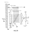
ケーブルは、大きいケーブルを含む複数の同軸ケーブルを固定および接続する「フレックス回路」法を使用することができる。例示的な実施態様では、アレイは、256個の素子を有する。アレイは、フレックス回路の中心領域に実装される。フレックス回路は、奇数の番号が付いた素子1、3、5、7...255が、J1というラベルが付いたBTH−090コネクタを有するフレックスの左端部上で終端し、偶数番号が付いた素子2、4、6、8...256が、J3というラベルが付いたBTH−090コネクタを有するフレックスの右端部で終端する両端を有する。両端では、これらの素子は、GND(信号リターン)ピンが、コネクタ全体に繰り返しパターンで均一に分散している個々のコネクタの上および下の列に沿って順に終端する。
The cable can use a “flex circuit” method to secure and connect multiple coaxial cables, including large cables. In the exemplary embodiment, the array has 256 elements. The array is implemented in the central region of the flex circuit. The flex circuit has an odd numbered
この繰返しパターンは、以下のとおり、フレックスの外側縁部からフレックスの中心領域に向かって画定される:
2つの信号ピン、GND
3つの信号ピン、GND
2つの信号ピン、GND
3つの信号ピン. . . .
.. . 、GND
3つの信号ピン、GND
2つの信号ピン、GND
2つの信号ピン、GND。
This repeating pattern is defined from the outer edge of the flex towards the central region of the flex as follows:
2 signal pins, GND
3 signal pins, GND
2 signal pins, GND
Three signal pins. . . .
. . . , GND
3 signal pins, GND
2 signal pins, GND
Two signal pins, GND.
折り畳まれたフレックス回路であって、アレイが、フレックスの中心アレイに実装されているフレックス回路の側面図を示す略図は、図12Aに示され、フレックス回路上のコネクタの関連するピン配列テーブルは、図12Bに示されている。 A schematic diagram showing a side view of a flex circuit that is a folded flex circuit, where the array is implemented in the central array of flexes, is shown in FIG. 12A, and the associated pinout table for the connectors on the flex circuit is It is shown in FIG. 12B.
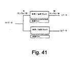
フレックス回路は、上記の例示的なケーブルに接続することができる。フレックス回路は、Precision Interconnect−Tyco Electronicsの医療用ケーブル組立体に接続することができる。フレックスからZIF(商標)コネクタまでの、たとえば電気接続は、2つの走査ヘッドPCBと、これに続く同軸ケーブルの束、および各々が、ZIF(商標)ピン内に挿入された2×15コネクタを有する12本の短いPCBによって行うことができる。 The flex circuit can be connected to the exemplary cable described above. The flex circuit may be connected to a Precision Interconnect-Tyco Electronics medical cable assembly. For example, an electrical connection from a flex to a ZIF ™ connector has two scan head PCBs followed by a bundle of coaxial cables, and each has a 2 × 15 connector inserted into a ZIF ™ pin. This can be done with 12 short PCBs.
各々の走査ヘッドPCB(合計2個)は、1つのBSH−090コネクタ、128のトレース(すべてのトレースは、たとえば30Hzで75Ωの制御されたインピーダンスを有する)を含むことができ、128(40AWG75Ω)の同軸ケーブルで終端することができる。PCBは、0.525”×2.344”の外側寸法を有することができる。 Each scan head PCB (2 total) can include one BSH-090 connector, 128 traces (all traces can have a controlled impedance of 75Ω at 30 Hz, for example), 128 (40 AWG 75Ω) It can be terminated with a coaxial cable. The PCB may have an outer dimension of 0.525 "x 2.344".
図13は、2つの走査ヘッドPCBの構造を示す。図14は、PCBをどのようにフレックス回路に接続することができるかを示し、同軸ケーブルのリボンをPCBにはんだ付けすることを可能にする千鳥状態を示す。2つの走査ヘッドPCBがある。左の基板は、フレックス上のJ1コネクタに接続することができ、右の基板は、J3コネクタに接続することができる。各々の走査ヘッドPCBは、1つのBSH−090コネクタを有することができる。各々の走査ヘッドのトレースのピン配列は、J1およびJ3コネクタのピン配列に一致適合させることができる。 FIG. 13 shows the structure of two scanning heads PCB. FIG. 14 shows how the PCB can be connected to the flex circuit and shows a staggered state that allows the ribbon of the coaxial cable to be soldered to the PCB. There are two scan heads PCB. The left board can be connected to the J1 connector on the flex, and the right board can be connected to the J3 connector. Each scan head PCB can have one BSH-090 connector. The pinout of each scan head trace can be matched to the pinout of the J1 and J3 connectors.
ZIFコネクタ
例示的な医療用ケーブルは、図15Aに部分的に示すように、処理ユニットに接続するケーブルの端部である近位端にZIFコネクタを備える。当業者は、ケーブル組立体のいくつかの構造が可能であることを理解するであろう。図15Bは、例示的なZIFコネクタに使用可能なピン配列を示す。Gというラベルを付けられたピンは、信号リターンピンである。N/Cというラベルを付けられたピンは同軸ケーブルで終端せず、これらのピンは、シャーシ接地を保護するか、または特定されていないその他の機能として使用するために留保される。N/Cピンは、単にZIF筐体を取り外し、ZIFに接続される12個のPCBの何れかの未使用のトレースのはんだを除去することによって接近することができる。
ZIF Connector An exemplary medical cable includes a ZIF connector at the proximal end, which is the end of the cable that connects to the processing unit, as partially shown in FIG. 15A. Those skilled in the art will appreciate that several configurations of cable assemblies are possible. FIG. 15B shows a pinout that can be used for an exemplary ZIF connector. The pin labeled G is a signal return pin. The pins labeled N / C are not terminated with a coaxial cable, and these pins are reserved for use in protecting chassis ground or for other functions not specified. The N / C pin can be accessed by simply removing the ZIF housing and removing the unused trace solder on any of the 12 PCBs connected to the ZIF.
ZIFコネクタに接続するために使用される12個の個々のPCBは、基板の一方または両方の側に接続される同軸ケーブルを有する。PCBの一方の縁部は、ZIFコネクタ(Saintec SSWまたは等価なもの)内に挿入するのに適するコネクタを有することができ、各々のPCBは、正しい同軸ケーブルを正しいZIFピンに接続するために必要な適切なトレースおよびバイアを有するべきである。 The twelve individual PCBs used to connect to the ZIF connector have coaxial cables connected to one or both sides of the board. One edge of the PCB can have a connector suitable for insertion into a ZIF connector (Saintec SSW or equivalent), each PCB being required to connect the correct coaxial cable to the correct ZIF pin Should have appropriate traces and vias.
各々のPCBは、Samtec SSWまたは等価なもの、2列の15個のピンを有するコネクタを有することができるが、同軸ケーブルの数は、図15Bに示すように12個のPCBによって異なる。2×15コネクタ上のピンの一般的な配置は普遍的であり、表1に示されている。 Each PCB can have a Samtec SSW or equivalent, a connector with 15 rows of 15 pins, but the number of coaxial cables varies with 12 PCBs as shown in FIG. 15B. The general arrangement of pins on a 2 × 15 connector is universal and is shown in Table 1.
12個のPCBの1つは、図15Bに示すとおり、EEPROMを含むトレースのレイアウトに備えを必要とする。12個のPCBの2つは、アレイ組立体内部に含まれる特定のアレイ構造を特定するPROBE ID番号を提供するために、必要に応じてピンのいくつかを終端させることが必要である。 One of the twelve PCBs requires provision for a trace layout that includes an EEPROM, as shown in FIG. 15B. Two of the twelve PCBs need to terminate some of the pins as needed to provide a PROBE ID number that identifies the particular array structure contained within the array assembly.
様々な接続方法を使用することができ、様々なスタイルのコネクタが挙げられる。これらの様々な接続方法では、インピーダンスは、30MHzの中心周波数において75Ωで良い。 Various connection methods can be used, including various style connectors. In these various connection methods, the impedance may be 75Ω at a center frequency of 30 MHz.

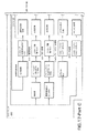
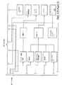
本発明による超音波システム1600の例示的な実施態様を図16に示す。図16は、例示的な超音波イメージングシステム1600を示すブロック図である。様々な図面に示されているブロックは、システム1600の一実施態様内で行われるプロセスの機能表現で良い。しかし、実際上、機能は、システム1600内のいくつかの位置またはモジュール全体で行われる。
例示的なシステム1600は、アレイ振動子1601、ケーブル1619、および処理ユニット1620を備える。ケーブル1619は、処理ユニット1620およびアレイ振動子1601を接続する。処理ユニットは、ソフトウェアおよびハードウェア構成要素を含む。処理ユニットは、マルチプレクサ(MUX)/フロントエンド電子回路1602、受信ビーム成形器1603、ビーム成形器制御装置1604、送信ビーム成形器1605、システム制御装置1606、ユーザインターフェース1607、走査変換器1608、映像処理ディスプレーユニット1609、および1つまたは複数のMモード処理モジュール(図示しない)を含む処理モジュール、PWドップラー処理モジュール1611、Bモード処理モジュール1612、カラーフロー処理モジュール1613、3−Dモード処理モジュール1615を含むことができる。例示的なシステムの中心周波数範囲は、約15〜55MHz以上で良い。帯域幅の外側縁部から測定した場合、例示的なシステムの周波数範囲は、約10〜80MHz以上で良い。
The
アレイ振動子1601は、MUX/フロントエンド電子回路(MUX/FEE)1602において、処理ユニット1620とインターフェースする。MUX/FEE1602のMUX部分は、複数の電気パスをより少数の電気パスに電子的に切り換えるか、または接続することが可能なマルチプレクサである。アレイ振動子1601は、電気エネルギーを超音波エネルギーに、およびこの逆に変換し、MUX/FEE1602に電気的に接続される。 The array transducer 1601 interfaces with the processing unit 1620 in the MUX / front end electronic circuit (MUX / FEE) 1602. The MUX portion of MUX / FEE 1602 is a multiplexer that can electronically switch or connect multiple electrical paths to fewer electrical paths. The array transducer 1601 converts electrical energy into ultrasonic energy and vice versa and is electrically connected to the MUX / FEE 1602.
MUX/FEE1602は、アレイの素子の一定のサブセット、つまりアクティブアパーチャの素子に接続される送信波形を生成する電子回路を含む。素子のサブセットは、アレイ振動子1601のアクティブアパーチャと呼ばれる。MUX/FEE1602の電子回路は、アレイのアクティブアパーチャを受信チャネルの電子回路にも接続する。作動時、アクティブアパーチャは、アレイ振動子1601の周囲で、本明細書に記載された構成要素によって決定される方法で移動する。 MUX / FEE 1602 includes electronic circuitry that generates a transmit waveform that is connected to a certain subset of the elements of the array, ie, the elements of the active aperture. The subset of elements is called the active aperture of the array transducer 1601. The MUX / FEE 1602 electronics also connect the array's active aperture to the receive channel electronics. In operation, the active aperture moves around the array transducer 1601 in a manner determined by the components described herein.
MUX/FEE1602は、アクティブアパーチャの素子を例示的なシステムの送信および受信チャネルに切換え可能に接続する。本発明の256素子アレイ振動子の例示的な実施態様では、最大64個のアクティブアパーチャに切換え可能に接続可能な64個の送信チャネルおよび64個の受信チャネルがある。最大64個のアクティブアパーチャは連続している。本発明の特定の実施態様では、別個の送信MUXおよび別個の受信MUXがある。本発明のその他の実施態様は、送信チャネルおよび受信チャネルの両方でMUXを共有する。 MUX / FEE 1602 switchably connects the elements of the active aperture to the transmit and receive channels of the exemplary system. In the exemplary embodiment of the 256 element array transducer of the present invention, there are 64 transmit channels and 64 receive channels that can be switchably connected to a maximum of 64 active apertures. A maximum of 64 active apertures are contiguous. In a particular embodiment of the invention, there is a separate transmit MUX and a separate receive MUX. Other embodiments of the invention share the MUX on both the transmit and receive channels.
例示的な超音波システム1600の送信サイクル時、MUX/FEE1602のフロントエンド電子回路部分は、アレイ振動子1601のアクティブアパーチャの素子に高電圧信号を供給する。一態様では、受信チャネルおよび送信チャネルは、アレイ振動子1601の素子に共通の接続点を有するため、フロントエンド電子回路は、受信チャネルの保護回路も提供し、受信チャネルを高電圧送信信号から保護することができる。保護は、受信チャネル内に漏れるか、または通過する可能性がある送信信号の量を、受信電子回路に損傷を生じない安全レベルに制限する絶縁回路構成の形式で良い。MUX/FEE1602の特徴としては、送信側における迅速な立上がり時間、および送信および受信チャネル上における高帯域幅が挙げられる。
During the transmit cycle of the
MUX/FEE1602は、信号を送信ビーム成形器1605からアレイ振動子1601に通過させる。例示的な実施態様では、送信ビーム成形器1605は、別個の波形を生成し、アクティブアパーチャの各々の素子に供給する。例示的な実施態様では、アクティブアパーチャの各々の素子の波形は同じである。別の態様では、アクティブアパーチャの各々の素子の波形は、すべて同じというわけではなく、実施態様によっては、異なる中心周波数を有する。 The MUX / FEE 1602 passes the signal from the transmission beam shaper 1605 to the array transducer 1601. In the exemplary embodiment, transmit beamformer 1605 generates a separate waveform and supplies it to each element of the active aperture. In the exemplary embodiment, the waveform of each element of the active aperture is the same. In another aspect, the waveforms of each element of the active aperture are not all the same, and in some implementations have different center frequencies.
例示的な一実施態様では、各々の別個の送信波形は、それぞれに関連する遅延を有する。各々の素子の波形の遅延の分布は、遅延プロファイルと呼ばれる。遅延プロファイルは、送信音響ビームを所望の焦点に所望どおりに集束させるように計算される。特定の実施態様では、送信音響ビーム軸は、アレイ1601の平面に垂直であり、ビーム軸は、アレイ振動子1601のアクティブアパーチャの中心でアレイ1601と交差する。遅延プロファイルも、ビームがアレイ1601の平面に垂直ではないように、ビームをステアリングすることができる。本発明の例示的な態様では、1/16の遅延分解能を使用することができる。あるいは、言い換えれば、送信中心周波数の中心周波数の期間の1/16は、別の遅延分解能だが、本発明の範囲内で考えられる。たとえば、50MHzの中心周波数では、期間は20ナノ秒であるから、期間の1/16は1.25ナノ秒であり、これは、音響ビームを集束させるために使用される例示的な遅延分解能である。遅延分解能は、期間の1/16番目とは異なる場合があり、たとえば、1/16番目より小さい遅延分解能(たとえば、1/24、1/32など)、および1/16より大きい遅延分解能(たとえば、1/12、1/8など)は、本発明の範囲内であると考えられることが分かるであろう。 In one exemplary implementation, each separate transmit waveform has a delay associated with it. The delay distribution of the waveform of each element is called a delay profile. The delay profile is calculated to focus the transmitted acoustic beam to the desired focus as desired. In certain embodiments, the transmit acoustic beam axis is perpendicular to the plane of the array 1601 and the beam axis intersects the array 1601 at the center of the active aperture of the array transducer 1601. The delay profile can also steer the beam so that the beam is not perpendicular to the plane of the array 1601. In exemplary aspects of the invention, a delay resolution of 1/16 can be used. Or, in other words, 1/16 of the center frequency period of the transmission center frequency is another delay resolution, but is considered within the scope of the present invention. For example, at a center frequency of 50 MHz, the period is 20 nanoseconds, so 1/16 of the period is 1.25 nanoseconds, which is an exemplary delay resolution used to focus the acoustic beam. is there. The delay resolution may be different from 1 / 16th of the period, for example, less than 1 / 16th delay resolution (eg, 1/24, 1/32, etc.) and greater than 1 / 16th delay resolution (eg, , 1/12, 1/8, etc.) will be considered within the scope of the present invention.
受信ビーム成形器1603は、MUX/FEE1602を介して、アレイ振動子101のアクティブアパーチャの素子に接続することもできる。送信時、音響信号は、被検体内に浸透し、被検体の組織から反射信号を生成する。反射信号は、アレイ振動子1601のアクティブアパーチャの素子によって受信され、アクティブアパーチャの各々の素子から放射されるアナログ電気信号に変換される。電気信号がサンプリングされ、信号は、受信ビーム成形器1603内でアナログからデジタル信号に変換される。本発明の実施態様は、直交サンプリングを使用して、受信信号のデジタル化を行う。システム1600の受信サイクルでは、アレイ振動子1601は、システム1600の受信サイクルでは、アレイ振動子1601は、ビーム成形器制御装置1604によって決定される受信アパーチャも有し、ビーム成形器制御装置1604は、受信ビーム成形器1603に対して、アレイのどの素子をアクティブアパーチャ内に含み、どの遅延プロファイルを使用するかを知らせる。例示的な実施態様の受信ビーム成形器1603は、デジタルビーム成形器である。
The reception beam shaper 1603 can also be connected to the element of the active aperture of the
受信ビーム成形器1603は、遅延をアクティブアパーチャの各々の素子の受信信号内に遅延を導入する。この遅延は、遅延プロファイルと総称される。受信遅延プロファイルは、経過時間、つまりイメージングされる組織内に超音波が送信される時に、経過した時間に基づいて動的に調節することができる。経過時間は、受信ビーム成形器を組織内の焦点の1点に集束させるために使用される。つまり、受信ビームは、送信ビームの経過時間に関する情報を含む遅延プロファイルを使用して調節される。 The receive beamformer 1603 introduces a delay into the received signal of each element of the active aperture. This delay is collectively referred to as a delay profile. The reception delay profile can be dynamically adjusted based on the elapsed time, that is, when the ultrasound is transmitted into the tissue being imaged. The elapsed time is used to focus the receive beamformer to one point of focus within the tissue. That is, the receive beam is adjusted using a delay profile that includes information about the elapsed time of the transmit beam.
アクティブアパーチャの各々の素子からの受信信号は合計され、合計は、遅延プロファイルを含む。合計受信信号は、ユーザインターフェース1607、およびユーザの入力に基づいて動作するシステム制御装置1606によって選択されるように、受信チャネルに沿って、受信ビーム成形器1603から、図16に示さないものも含み)1つまたは複数の処理モジュール1611、1612、1613、および/または1615流れる。
The received signals from each element of the active aperture are summed and the sum includes a delay profile. Total received signals also include those not shown in FIG. 16 from the receive beamformer 1603 along the receive channel, as selected by the user interface 1607 and the system controller 1606 that operates based on user input. ) One or
ビーム成形器制御装置1604は、送信ビーム成形器1605および受信ビーム成形器1603を介してMUX/FEE1602に接続される。ビーム成形器制御装置1604は、システム制御装置1606にも接続される。ビーム成形器制御装置1604は、MUX/FEE1602に情報を提供し、その結果、アレイ振動子1601の所望の素子は、アクティブアパーチャを形成するように接続される。また、ビーム成形器制御装置1604は、特定のビームの受信に使用される遅延プロファイルを生成し、受信ビーム成形器1603に送信する。本発明の実施態様では、受信遅延プロファイルは、経過時間に基づいて、繰返し更新することができる。ビーム成形器制御装置1604は、送信遅延プロファイルも生成し、送信ビーム成形器1605に送信する。 The beam shaper controller 1604 is connected to the MUX / FEE 1602 via the transmission beam shaper 1605 and the reception beam shaper 1603. The beam shaper controller 1604 is also connected to the system controller 1606. The beam shaper controller 1604 provides information to the MUX / FEE 1602 so that the desired elements of the array transducer 1601 are connected to form an active aperture. Further, the beam shaper control device 1604 generates a delay profile used for receiving a specific beam, and transmits the delay profile to the reception beam shaper 1603. In an embodiment of the present invention, the reception delay profile can be repeatedly updated based on the elapsed time. The beam shaper controller 1604 also generates a transmission delay profile and transmits it to the transmission beam shaper 1605.
システム制御装置1606は、当業者が周知している方法で動作する。システム1600は、ユーザインターフェース1607から入力を取得し、制御情報をシステム1600の様々な構成要素に提供し、選択された動作モードになるようにシステム1600を構成する。走査変換器1608は、当該技術分野で周知の方法で動作し、1つまたは複数の処理モジュールから生成された生画像データを取得して、この生画像データを、映像処理/ディスプレー1609によって表示可能な画像に変換する。動作の処理モードでは、画像は、画像の映像特性が、ディスプレーの映像特性と同じであれば、走査変換器1608を使用しないで表示することができる。
The system controller 1606 operates in a manner well known to those skilled in the art. The
処理モジュールは、本明細書に特記しない限り、当業者が周知している方法で機能する。PWドップラーモジュール1611、およびカラーフロー処理モジュール1613では、パルス繰返し周波数(PRF)は、本発明の実施態様の高い中心周波数により高い可能性がある。測定される最大非エイリアス速度は、PRFに比例し、送信中心周波数に反比例する。特定の送信中心周波数が、当業者が周知している方法で計算されると仮定すると、PRFは、非エイリアス測定を可能にするために必要である。使用される送信中心周波数が、15〜55MHz以上であり、血流速度が、1m/秒という速さ、および場合によっては1m/秒を超えると仮定すると、こうした速度から生じるドップラー信号の非エイリアス測定は、PWドップラーを150KHz以下にするために、PRFを必要とする。本発明の実施態様は、150KHz以下のPRFを支持するPWドップラーモードを有し、このモードは、中心周波数が30MHzの場合、移動する目標の速度ベクトルと超音波ビーム軸との間の角度が0度の状態で、1.9m/秒以下の血流速度の非エイリアス測定を可能にする。
The processing module functions in a manner well known to those skilled in the art unless otherwise specified herein. In the PW Doppler module 1611 and the color
特定に実施態様では、RFモジュール1615は補間を使用する。使用されるサンプリング方法が直交サンプリングである場合、RF信号は、当業者が周知のゼロパディングおよびフィルタリングによって、直交ベースバンドサンプルから再現することができる。Nyquistサンプリングを使用する場合、RF信号が直接サンプリングされるため、再現は不要である。特定の実施態様では、RFモジュール1615は、受信ビーム成形器出力の直交サンプルからRF信号を生構成する。サンプリングは、受信信号の中心周波数で行われるが、直交の場合、信号のベースバンド直交表現が与えられる。RF信号は、直交サンプリングされたデータ流を最初にゼロパディングすることによって生成され、ゼロの数は、所望の補間信号サンプルレートによって決定される。次に、複合帯域フィルタは、ゼロパディングされたデータ流に適用され、fsがサンプル周波数であるfs/2〜3fs/2の周波数帯域外にあるゼロパディングされた信号の周波数成分を拒絶する。フィルタリング後の結果は、元のRF信号の複素表現である。次に、RF信号は、メインコンピュータユニットに送られ、デジタルフィルタリング、並びに包絡線検波および表示など、その他の処理が行われる。RF信号の実数部または複素表現が表示される。たとえば、特定の走査ラインに関して取得されたRFデータが処理され、表示される。あるいは、多数のパルスエコーリターンを平均した特定の走査ラインからのRFデータを表示することができるか、または多数の異なる走査ラインから取得したRFデータを平均し、表示することができる。RFデータの取得に使用される走査ラインは、Bモード画像上に重なったカーソルラインを配置することによって、ユーザが、Bモードの評価に基づいて指定することができる。RFデータの高速フーリエ変換(FFT)を計算して、表示することもできる。RFデータの取得およびBモードデータの取得は、リアルタイムで同時に、両方のモードからの情報を表示することができるように、インターリーブすることができる。ECG信号などの生理学的信号の取得も、RFデータの取得と同時に行うことができる。ECG波形は、RFデータが取得されている間に表示することができる。RFデータの取得のタイミングは、ECG波形内のユーザが画定した点と同期させて、それによって、心周期時に特定回数だけRFデータを参照することが可能になる。RFデータを記録して、その後のある時点で処理および評価することができる。 In particular embodiments, the RF module 1615 uses interpolation. If the sampling method used is quadrature sampling, the RF signal can be reconstructed from the quadrature baseband samples by zero padding and filtering well known to those skilled in the art. When using Nyquist sampling, the RF signal is sampled directly, so no reproduction is necessary. In a particular implementation, the RF module 1615 generates an RF signal from orthogonal samples of the receive beamformer output. Sampling is performed at the center frequency of the received signal, but in the case of orthogonality, a baseband orthogonal representation of the signal is given. The RF signal is generated by first zero padding the orthogonally sampled data stream, the number of zeros being determined by the desired interpolated signal sample rate. The composite band filter is then applied to the zero padded data stream and rejects frequency components of the zero padded signal that are outside the frequency band of fs / 2 to 2 fs / 2 where fs is the sample frequency. The result after filtering is a complex representation of the original RF signal. The RF signal is then sent to the main computer unit for other processing such as digital filtering and envelope detection and display. The real part or complex representation of the RF signal is displayed. For example, RF data acquired for a particular scan line is processed and displayed. Alternatively, RF data from a particular scan line averaged over multiple pulse echo returns can be displayed, or RF data acquired from a number of different scan lines can be averaged and displayed. The scan line used for acquiring the RF data can be designated by the user based on the evaluation of the B mode by arranging the cursor line overlapping the B mode image. A fast Fourier transform (FFT) of the RF data can also be calculated and displayed. Acquisition of RF data and acquisition of B-mode data can be interleaved so that information from both modes can be displayed simultaneously in real time. Acquisition of physiological signals such as ECG signals can also be performed simultaneously with the acquisition of RF data. The ECG waveform can be displayed while RF data is acquired. The timing of acquisition of the RF data is synchronized with a user-defined point in the ECG waveform, which allows the RF data to be referenced a specific number of times during the cardiac cycle. RF data can be recorded and processed and evaluated at some point thereafter.
図17は、本発明の一実施態様の構成要素をさらに示すシステム1600のブロック図を示す。アレイ振動子1601は、ケーブル1619を介してフロントエンド変換器1702に接続される。ケーブル1619は、アレイ振動子1601の素子からフロントエンド変換器1702までの信号経路を含む。ケーブルの例示的な実施態様は、本明細書で説明されており、個々のマイクロ同軸ケーブルを含む。さらに、コネクタは、ケーブル1619の一方の端部または両方の端部に使用することができる。本発明の一態様では、素子の数の2倍に相当するピンを有するコネクタを使用することができ、例示的なコネクタは、本明細書で説明されている。アレイ振動子1601の各々の素子では、信号および接地パスを使用することができる。本発明のその他の実施態様では、接地接続は、素子群ごとに共用される。あるいは、MUX/フロントエンド電子回路1702、1703、1704、1708は、線形振動子アレイ1601用の筐体内に配置することができる。
FIG. 17 shows a block diagram of a
図17は、フロントエンド変換器1702および送信出力ステージ1703が各々の素子に存在する比較的大きいシステム1600の例として、アレイ振動子1601の4つの素子のための回路構成の代表的な詳細を示す。256素子のアレイ振動子1601を有する一実施態様の場合、256個のフロントエンド変換器1702および送信出力ステージ1703について、以下でさらに完全に説明する。受信時、アレイ振動子1601の素子からの電気信号は、フロントエンド変換器1702を通過して、受信マルチプレクサ1704内に入る。受信マルチプレクサ1704は、どの素子およびフロントエンド変換器を受信チャネル1705に接続するかを選択する。受信チャネル1705は、低雑音増幅器およびタイムゲインコントロールを備え、両者について、以下でさらに完全に説明する。信号は、次に、受信チャネル1705からアナログデジタル変換1706内に至り、そこでデジタル化される。デジタル受信信号は、次に、デジタルビーム成形器である受信ビーム成形器1707内に入る。ブロック1707では、ビーム成形器制御装置内で生成された遅延プロファイルは、受信信号に適用される。受信ビーム成形器1707からの信号は、合成アパーチャメモリ1710内に移動する。合成アパーチャメモリは、2つの連続する超音波ラインからの受信データを追加する。超音波ラインは、超音波パルスが組織内に送信された後に受信される超音波エコーを返すことによって生じるデータであると考えられる。合成アパーチャイメージングは、当業者が理解するように実施される。部分的には、合成アパーチャイメージングは、送信または受信アパーチャの有効サイズを増加する方法を意味する。たとえば、ビーム成形器内に64個のチャネルがある場合、1本の超音波ラインデータの受信時に、64個の送信チャネル、および64個の受信チャネルを使用することができる。合成アパーチャイメージングは、合計2本の超音波データラインを使用する。第1超音波ラインは、素子33から96にわたる受信アパーチャを使って取得することができる。第2超音波ラインは、素子1〜32および97〜128に位置する2つのブロックに区分されたアパーチャを使って受信される。両方の超音波ラインは、同じ送信アパーチャを使用する。2本の超音波ラインを加算する場合、受信アパーチャが、素子1から128に位置する128個のチャネルから成るとして、結果として得られる超音波ラインは、受信された超音波ラインと本質的に同じだが、2本の超音波データラインを取得するために必要な期間に、イメージングされる組織に感知可能な動きはないことが条件である。この場合、フレームレートは2分の1に低下するため、1本ではなく2本の超音波ラインが必要である。2つの受信アパーチャは、一緒に128個の素子のアパーチャを形成する限り、異なる方法で配置することができる。あるいは、送信アパーチャのサイズは、受信アパーチャを同じに維持しながら、増加させることができる。2本を超える超音波ラインは、アパーチャを2倍に増加するために使用することができる。合成アパーチャメモリ1710からの信号は、次に、RFシネバッファ1713内に記憶され、このRFシネバッファ1713は、同期処理制御モジュール1714によって制御されるように、多くの受信RFラインを記憶する大型メモリである。バッファされた受信信号は、次に、適切な速度で信号処理ユニット1715内に読み込まれる。信号処理ユニット1715は、ビーム成形器制御盤上において、専用CPUで実施される。受信信号は、信号処理ユニット1715からコンピュータユニット1717に送られ、ユーザが選択したモードに従ってさらに処理される。コンピュータユニット1717による受信信号の処理は、一般に、本明細書に特記する場合を除いて、当業者が周知するタイプである。
FIG. 17 shows representative details of the circuit configuration for the four elements of the array transducer 1601, as an example of a relatively
一実施態様では、コンピュータユニット1717は、図17に示すとおり、コンピュータユニット1717は、システムの動作モードに従って信号を処理するように構成されたシステムソフトウェアを含む。たとえば、メインコンピュータユニット1717のシステムソフトウェアは、Bモードプロセッサを実行するように構成され、たとえば、前処理、パーシスタンス処理、シネループ画像バッファ、走査変換、イメージパン、ズーム、および後処理を含む。メインコンピュータユニット1717のシステムソフトウェアは、カラーフローイメージング(CFI)のための処理を実行するように構成することもでき、たとえば、閾値決定マトリックス、推定値フィルタリング、パーシスタンスおよびフレーム平均化、シネループCFI画像バッファ、走査変換、カラーマップ、および優先度を含む。メインコンピュータユニット1717のシステムソフトウェアは、PWドップラーのための処理を実行するように構成することもでき、たとえば、スペクトル推定(FFT)、推定値フィルタリング、シネループスペクトルデータバッファ、スペクトル表示の生成、後処理、ダイナミックレンジ、および音響処理を含む。 In one embodiment, the computer unit 1717 includes system software configured to process signals according to the operating mode of the system, as shown in FIG. For example, the system software of the main computer unit 1717 is configured to execute a B-mode processor and includes, for example, preprocessing, persistence processing, cineloop image buffer, scan conversion, image panning, zooming, and postprocessing. The system software of the main computer unit 1717 can also be configured to perform processing for color flow imaging (CFI), such as threshold determination matrix, estimate filtering, persistence and frame averaging, cineloop CFI images. Includes buffers, scan conversions, colormaps, and priorities. The system software of main computer unit 1717 can also be configured to perform processing for PW Doppler, for example, spectral estimation (FFT), estimation filtering, cine loop spectral data buffer, generation of spectral display, post-processing Includes processing, dynamic range, and acoustic processing.
図17のシステムの実施態様は、ユーザインターフェースパネル1720も備える。この実施態様では、ユーザインターフェースパネル1720は、殆どの臨床超音波システムに見られる標準ユーザインターフェースに類似している。たとえば、Bモードユーザインターフェースは、画像の奥行き、画像のサイズ、二重画像作動、二重画像左/右選択、フリップ画像上/下、およびズームを含む画像フォーマット制御装置を有する。送信制御装置は、送信電力(送信振幅)、送信焦点領域の位置、送信域の数の選択、送信周波数、およびサイクル数を含む。画像最適化制御装置は、Bモードゲイン、TGCスライダー、前処理、パーシスタンス、ダイナミックレンジ、フレームレート/分解能制御、および後処理曲線を含む。
The system embodiment of FIG. 17 also includes a
モード依存インターフェース制御装置のもう1つの例として、カラーフローイメージングユーザインターフェースは、カラーフローモード選択(たとえば、カラーフロー速度、パワードップラー、組織ドップラー)、トラックボール、ステアリング角度、カラーボックスの位置/サイズの選択(選択後、トラックボールを使用して、位置またはサイズを調節する)、プリセットリコール、プリセットメニュー、およびカラーマップ反転を含む画像フォーマット制御装置を有する。送信制御は、送信電力(送信振幅)、送信焦点領域の位置、および送信周波数を含む。画像最適化制御は、カラーフローゲイン、ゲートサイズ、PRF(速度スケールの変更)、クラッタフィルタの選択、クラッタフィルタの選択、フレームレート/分解能の制御、前処理の選択、パーシスタンス、ダイナミックレンジ(パワードップラーの場合のみ)、およびカラーマップの選択を含む。 As another example of a mode-dependent interface controller, the color flow imaging user interface is a color flow mode selection (eg, color flow speed, power Doppler, tissue Doppler), trackball, steering angle, color box position / size It has an image format controller that includes selection (uses a trackball to adjust position or size after selection), preset recall, preset menu, and color map inversion. The transmission control includes transmission power (transmission amplitude), the position of the transmission focal region, and the transmission frequency. Image optimization control includes color flow gain, gate size, PRF (speed scale change), clutter filter selection, clutter filter selection, frame rate / resolution control, preprocessing selection, persistence, dynamic range (power Including Doppler only), and colormap selection.
ユーザインターフェースのさらに別の実施例は、PWドップラーモードの選択、トラックボール、PWカーソルの作動(トラックボールは、サンプルボリューム位置を調節するために使用される)、サンプルボリュームサイズ、ドップラーステアリング角度、掃引速度、更新(同時または間隔更新イメージングを選択)、音響ボリューム制御、および流れベクトルの角度を含むPWドップラーフォーマット制御装置を有するPWドップラーユーザインターフェースである。送信制御は、送信電力(送信振幅)および送信周波数を含む。スペクトル表示最適化制御は、ドップラーゲイン、スペクトル表示のサイズ、PRF(速度スケールの変更)、クラッタフィルタの選択、前処理およびダイナミックレンジを含む。 Yet another embodiment of the user interface includes PW Doppler mode selection, trackball, PW cursor activation (trackball is used to adjust sample volume position), sample volume size, Doppler steering angle, sweep PW Doppler user interface with PW Doppler format controller including velocity, update (select simultaneous or interval update imaging), acoustic volume control, and flow vector angle. The transmission control includes transmission power (transmission amplitude) and transmission frequency. Spectral display optimization control includes Doppler gain, spectral display size, PRF (change speed scale), clutter filter selection, pre-processing and dynamic range.
例示的なMモードのユーザインターフェースは、Mモードカーソル作動、トラックボール(カーソルの位置決めに使用)、ストリップサイズ、および掃引速度を含む画像フォーマット制御を有する。送信制御は、送信電力(送信振幅)、送信焦点領域の位置、送信周波数、およびサイクル数を含む。画像最適化制御は、Mモードゲイン、前処理、ダイナミックレンジ、および後処理を含む。 An exemplary M-mode user interface has image format controls including M-mode cursor actuation, trackball (used for cursor positioning), strip size, and sweep speed. The transmission control includes transmission power (transmission amplitude), transmission focal region position, transmission frequency, and cycle number. Image optimization control includes M-mode gain, pre-processing, dynamic range, and post-processing.
例示的なRFモードユーザインターフェースは、たとえば、RFライン位置、RFゲート、取得したRFラインの数、RF領域の動作、RF領域の位置、RF領域のサイズ、領域内のRFラインの数、平均化、およびBモードインターリーブディスエーブルを含むRFライン取得制御を有する。送信制御は、送信電力(送信振幅)、送信焦点領域の位置、送信f番号、送信周波数、サイクル数、取得PRFおよびステアリング角度を含む。受信処理制御は、RFモードゲイン、フィルタタイプと順序、ウィンドウのタイプ、および平均化されたライン数を含む。 An exemplary RF mode user interface includes, for example, RF line position, RF gate, number of acquired RF lines, RF region operation, RF region position, RF region size, number of RF lines in region, averaging And RF line acquisition control including B-mode interleave disable. The transmission control includes transmission power (transmission amplitude), position of the transmission focal region, transmission f number, transmission frequency, number of cycles, acquisition PRF, and steering angle. Receive processing controls include RF mode gain, filter type and order, window type, and number of lines averaged.
受信信号のデジタルサンプルは、データが取得されるレートと一般に異なるレートで処理される。こうした処理は、本明細書では、「非同期信号処理」と記載する。処理レートは、データが表示されるレートであり、一般に毎秒約30フレーム数(fps)である。しかし、理解されるように、データは、最高で取得レートのレートで表示されるか、または約30fps未満で表示することができる。データは、本発明の特定の実施態様では、はるかに迅速なフレームレート、毎秒約300フレーム、または望ましい診断情報を取得するのに必要な速度で取得することができる。たとえば、迅速に移動する解剖学的構造、たとえば心臓弁の画像データは、比較的速いフレームレートを使用して取得され、次に比較的遅いフレームレートで表示することができる。データ取得レートは、30fps未満、30fps、または30fpsを超えて良い。たとえば、取得レートは、50、100、200、300、またはそれ以上のfpsで良い。 Digital samples of the received signal are processed at a rate that is generally different from the rate at which data is acquired. Such processing is referred to herein as “asynchronous signal processing”. The processing rate is a rate at which data is displayed, and is generally about 30 frames per second (fps). However, as will be appreciated, the data can be displayed at a rate of up to the acquisition rate or less than about 30 fps. Data can be acquired in a particular embodiment of the present invention at a much faster frame rate, about 300 frames per second, or at the rate necessary to obtain the desired diagnostic information. For example, rapidly moving anatomical structures, such as heart valve image data, can be acquired using a relatively fast frame rate and then displayed at a relatively slow frame rate. The data acquisition rate may be less than 30 fps, 30 fps, or greater than 30 fps. For example, the acquisition rate may be 50, 100, 200, 300, or more fps.
表示レートは、ヒトの眼が処理可能なレートを超えないように設定することができる。取得可能なフレームによっては、表示の際にスキップすることができるが、受信ビーム成形器の出力からのすべてのデータは、RFシネバッファ1713などのRFデータバッファに記憶される。データは、RFデータと呼ばれることもあり、あるいはデータを取得するために使用されるサンプリング方法で呼ばれることもある(たとえば、直交サンプリングの場合、データは、ベースバンド直交データと呼ぶこともできる)。直交またはRFデータは、表示前に処理される。処理は計算集約的であり、使用する処理量を減少すると有利であり、これは、取得レートではなく、表示レートで表示されるフレームのみを処理することによって達成される。表示の際にスキップされたフレームは、ライブイメージングが停止するか、またはシステムが「凍結」されると閲覧することができる。RFバッファ1713内のフレームは、比較的低いレートで検索、処理、および再生することができ、たとえば、取得レートが毎秒300フレームである場合、毎秒30フレームにおけるフレームごとの再生は、通常の10分の1の遅さになるが、操作者は、画像の迅速な変化を見ることが可能になる。再生機能は、一般に、当業者によって「シネループ」機能と呼ばれている。画像は、様々なレートで再生するか、フレームごとに、後方、および前方に再生することができる。
The display rate can be set so as not to exceed a rate that can be processed by the human eye. Although some frames can be skipped during display, all data from the output of the receive beamformer is stored in an RF data buffer, such as
図17に示すシステム1600は、当業者が、システムの機能として望ましいと認識すると思われる様々な項目を含むことができ、たとえば、クロック1712、メモリ、音声カードおよびスピーカ、映像カードおよびディスプレーなど、並びに図17に示すその他の機能ブロックがある。
The
図18aおよび18bは、MUX/フロントエンド電子回路1702、1703、1704、1708の一実施態様、並びに本発明の一実施態様による受信ビーム成形器1707および送信ビーム成形器1709の機能の追加の詳細を示す。図18aに示す実施態様では、チャネル、たとえば受信チャネルはノードに接続することができ、このノードは、図18aに示すように、切換え回路または多重化回路を通して、たとえば、アレイ振動子1601の4つの素子に接続される。たとえば、チャネル1 1801は、図18aの参照符号1、65、129、および193の素子に切換え可能に接続され、これらの4つの素子の1つのみが、任意の特定の時にチャネル1 1801に接続される。これは、本質的に、システム1600の受信サイクルにおけるMUX/フロントエンド電子回路1702、1703、1704、1708の多重化機能の実行である。あるチャネルに切換え可能に接続される4つの素子の割当ては、素子の特定のサブセットの連続素子が、アクティブアパーチャを含むように行われる。たとえば、アレイ振動子が、256個の素子から成る場合、64個以下の素子が、アクティブアパーチャを含むサブセットを形成することができる。
FIGS. 18a and 18b provide additional details of one embodiment of the MUX /
受信サイクルのアレイ振動子1601の素子の多重化は、フロントエンド1802の例示的な図(図18b)に示されているRXスイッチ1817によって行うことができる。ビーム成形器制御装置1711からの制御信号1818は、どのRXスイッチ1817を作動させ、それによって、モジュール1802の4つの利用可能な素子の選択された素子を受信チャネルに接続するかを決定する。当業者が理解するとおり、図18aおよび18bにに示す多重化スキームは、異なる数の素子(256個の素子以外)、および異なる最大アクティブアパーチャサイズ(最大64個の素子以外)の振動子に適用することができる。
Multiplexing the elements of the array transducer 1601 in the receive cycle can be performed by the RX switch 1817 shown in the exemplary diagram of the front end 1802 (FIG. 18b).
図18bに示す例示的なフロントエンド1816は、以下で招請に説明するとおり、変換器1819およびパルサー1820も備える。一態様では、フロントエンド1816は、上記のとおり、受信チャネルを送信波形から絶縁する。 The exemplary front end 1816 shown in FIG. 18b also includes a transducer 1819 and a pulsar 1820, as described below in the invitation. In one aspect, the front end 1816 isolates the receive channel from the transmit waveform, as described above.
選択されたアレイ振動子素子からの受信信号は、低雑音増幅器(LNA)1804に送られる。増幅された信号は、LNA1804から、タイムゲインコントロール(TGC)1805に送られる。経過時間は、受信反射信号の深さに比例するため、深さ依存ゲイン制御とも呼ばれる。超音波システムでは、超音波の送信から時間が経過すると、選択された信号もこうした減衰を生じる。TGC1805は、時間依存性関数に応じて受信信号を増幅し、この減衰を補償する。時間依存TGCゲインを決定するために使用可能な要素は、経過時間、調査される被検体または被検組織の組織の特性、および用途(たとえば、画像診断法)である。ユーザは、ユーザインターフェースパネル1607におけるTGC制御を調節することによって、ゲインを深さの関数として指定することもできる。各実施態様は、たとえば、Analog Devices(マサチューセッツ州、ノーウッド)のAD8332または類似のデバイスを使用して、LNA1804およびTGC1805の機能を実行することができる。受信信号は、TGC1805から、受信ビーム成形器1803に入り、サンプラーによって、この実施態様ではアナログデジタル変換器1807および1808によってサンプリングされる。本発明によるその他の実施態様では、サンプリングが、Nyquistレートを超えるレート、たとえばNyquistレートの2倍または3倍で行われる場合、1つのアナログデジタル変換器のみが使用され、Nyquistレートでは、信号の最高周波数の少なくとも2倍のレートで、個々の素子から超音波信号がサンプリングされる。 A reception signal from the selected array transducer element is sent to a low noise amplifier (LNA) 1804. The amplified signal is sent from the LNA 1804 to a time gain control (TGC) 1805. Since the elapsed time is proportional to the depth of the received reflected signal, it is also called depth-dependent gain control. In an ultrasound system, the selected signal also undergoes such attenuation over time after transmission of the ultrasound. The TGC 1805 amplifies the received signal according to the time dependency function and compensates for this attenuation. Factors that can be used to determine the time-dependent TGC gain are the elapsed time, the tissue characteristics of the subject or tissue being examined, and the application (eg, imaging method). The user can also specify the gain as a function of depth by adjusting the TGC control in the user interface panel 1607. Each implementation may perform the functions of LNA 1804 and TGC 1805 using, for example, AD8332 from Analog Devices (Norwood, Mass.) Or a similar device. The received signal enters the receive beamformer 1803 from the TGC 1805 and is sampled by the sampler, in this embodiment by analog to digital converters 1807 and 1808. In other embodiments according to the present invention, if sampling is performed at a rate above the Nyquist rate, for example twice or three times the Nyquist rate, only one analog-to-digital converter is used, and at the Nyquist rate, the highest signal Ultrasonic signals are sampled from the individual elements at a rate of at least twice the frequency.
本発明のその他の実施態様では、直交サンプリングが使用され、2つのアナログデジタル変換器、つまり「I」および「Q」サンプラーが使用される。受信ビーム成形器1803の例示的な実施態様では、受信信号は、ブロック1807および1808で、直交サンプリングアナログデジタル変換器(ADC)を使用してデジタル化され、サンプリングクロックが、90°位相が外れいてる2つのADCがチャネルごとに必要である。使用されるサンプルレートは、受信信号の中心周波数で良い。比較すると、直接サンプリングは、理論上、受信信号の最高周波数成分の少なくとも2倍のサンプリングレートを使用するが、事実上、少なくとも3倍のサンプリングレートが好ましい。直接サンプリングは、チャネルごとに1つのADCを使用する。 In other embodiments of the present invention, quadrature sampling is used and two analog-to-digital converters are used, an “I” and “Q” sampler. In the exemplary implementation of receive beamformer 1803, the received signal is digitized using an orthogonal sampling analog to digital converter (ADC) at blocks 1807 and 1808, and the sampling clock is 90 degrees out of phase. Two ADCs are required per channel. The sample rate used may be the center frequency of the received signal. In comparison, direct sampling theoretically uses a sampling rate that is at least twice the highest frequency component of the received signal, but in practice a sampling rate of at least three times is preferred. Direct sampling uses one ADC per channel.
サンプリング後、現在のデジタル化受信信号は、フィールドプログラマブルゲートアレイ(FPGA)内に送られ、受信ビームの形成に関連する様々な機能がインプリメントされる。FPGA内では、デジタル化受信信号には、ADCのDCオフセットの補正が行われる。各々のADCは、異なるDCオフセット補正値を有する。DCオフセットは、ADCの出力部で得られる多数のデジタルサンプルを平均化することによって決定され、たとえば、システム始動時の校正期間中、受信チャネル入力部に信号は存在しない。デジタル化信号は、次に、FIFOバッファ1822内に送られ、各々のサンプルは、適切な期間にわたって記憶され、その結果、適切な遅延プロファイルをインプリメントすることができる。粗遅延は、信号を1つまたは複数のサンプル点だけシフトさせて、所望の遅延を取得することによってインプリメントすることができる。たとえば、所望の遅延が1サンプル期間である場合、1サンプルだけ適切な方向にシフトすることによって、適切な遅延を有する信号が得られる。しかし、サンプル期間に等しくない値の遅延が望ましい場合、補間フィルタ1809を使用して、微細遅延をインプリメントすることができる。
After sampling, the current digitized received signal is sent into a field programmable gate array (FPGA) to implement various functions related to forming the receive beam. In the FPGA, correction of the DC offset of the ADC is performed on the digitized reception signal. Each ADC has a different DC offset correction value. The DC offset is determined by averaging a number of digital samples obtained at the output of the ADC, eg, no signal is present at the receive channel input during the calibration period at system startup. The digitized signal is then sent into the FIFO buffer 1822 and each sample is stored for an appropriate period of time so that an appropriate delay profile can be implemented. Coarse delay can be implemented by shifting the signal by one or more sample points to obtain the desired delay. For example, if the desired delay is one sample period, shifting in the appropriate direction by one sample will result in a signal with the appropriate delay. However, if a delay of a value not equal to the sample period is desired, an
デジタル化受信信号は、FIFOバッファ1822から補間フィルタ内に送られ、微細遅延の計算が行われる。補間フィルタ1809は、サンプル期間が、適切な微細遅延分解能を超えるシステムに使用される。たとえば、サンプルレートは、超音波信号の中心周波数であり、50MHzである場合、サンプルレートは20ナノ秒ごとに1サンプルである。しかし、1.25ナノ秒の遅延分解能(20ナノ秒の1/16)は、所望の画像品質を提供するために特定の実施態様に使用されるが、その他の遅延分解能は、本発明の範囲内ので考えられる。補間フィルタ1809は、適時に、サンプリングされた点以外の点における信号の値を計算するために使用される。補間フィルタ1809は、サンプリングされた信号の同相および直交部分に適用される。補間フィルタ1809の実施態様は、有限インパルス応答(FIR)フィルタを備える。各々のフィルタの係数は、経過時間に基づいてサンプルごとに、ビーム成形器制御装置によって動的に更新することができる。補間フィルタによる処理の後、位相回転は、同相および直交成分に適切な係数を乗算する乗算器1811によって適用することができる。位相回転は、ADCサンプル周波数に対する正しい位相を補間サンプルに組み入れるために使用される。RXコントローラ1810は、FIFOモジュールおよび補間フィルタを制御する。受信遅延は動的に更新されるため、各々のチャネルにおける補間フィルタ係数は、一定の間隔で変更する必要がある。FIFOによってインプリメントされる遅延も、一定の間隔で変更する必要がある。また、受信アパーチャのサイズは動的に調節されるため、各々のチャネルは、超音波信号の受信時の特定の時間にアクティブになり、チャネルは、「乗算」モジュール1811において0ではなく1を乗算することによって作動される。また、乗算モジュール1811は、0と1との間の値である「重量」を受信アパーチャ内の各々のチャネルに個々に適用することができる。アポダイゼーションとして周知されているこのプロセスは、当業者が周知している。補間サンプルに乗算される値は、超音波信号の受信時に動的に拡大するアポダイズド受信アパーチャをインプリメントするように、時間に応じて異なる。
The digitized reception signal is sent from the FIFO buffer 1822 into the interpolation filter, and the fine delay is calculated.
図18cは、本発明による実施態様の受信コントローラ(RXコントローラ)の例示的な実施態様である。受信コントローラ1810は、正しい遅延プロファイル、アパーチャサイズ、および受信アポダイゼーションデータを、補間および位相回転アポダイゼーションをインプリメントする処理ブロック1809内にプログラムするために使用される。図18cの受信コントローラ1810は、初期パラメータ(初期粗遅延、初期位相)を開始(SOL)トリガごとに1回設定し、動的パラメータ(動的集束、動的アポダイゼーション)を受信クロック(RXCLK)期間ごとに1回設定する。初期受信遅延プロファイルは、RX初期アパーチャメモリ1822内に記憶される。動的受信遅延プロファイルは、RX動的アパーチャメモリ1824内に記憶される。遅延プロファイルは、SOLトリガの前に、64:16交差スイッチ1828を介して、RXBFバッファ1826内にロードされる。交差スイッチ1828は、64のアパーチャチャネル構成のうちの16を選択する。これらは、単一チャネル基板上に存在する16の受信チャネルをプログラムするために使用される。
FIG. 18c is an exemplary embodiment of a receive controller (RX controller) according to an embodiment of the present invention. Receive
各々の受信ラインの構成は、ラインメモリ1830内に記憶される。ラインメモリ1830内の各々のライン構成は、アパーチャ選択インデックス、モード選択、およびアパーチャイネーブルを含む。アパーチャ選択インデックスは、チャネルマッピングアパーチャを決定するために使用される。モード選択は、複数の遅延プロファイルにアクセスするために使用される。アパーチャイネーブルインデックスは、最初のアパーチャサイズを制御する。アパーチャ選択ルックアップテーブル(AP_SEL LUT)1832は、可能な構成の数を減少させ、その結果、ラインメモリ内に記憶する必要があるビット数を減少させる方法である。AP_SEL LUT1832は、再プログラム可能である。
The configuration of each reception line is stored in line memory 1830. Each line configuration in line memory 1830 includes an aperture selection index, a mode selection, and an aperture enable. The aperture selection index is used to determine the channel mapping aperture. Mode selection is used to access multiple delay profiles. The aperture enable index controls the initial aperture size. The aperture selection look-up table (AP_SEL LUT) 1832 is a way to reduce the number of possible configurations and, consequently, the number of bits that need to be stored in the line memory. The
メモリ制御装置1834は、ライン構成を復号する状態マシンである。状態マシンは、制御および状態メモリ1836によって構成される。状態マシンは、異なるモード(たとえば、Bモード、カラーフローモード、PWドップラーモードなど)の場合は別様に構成される。メモリ制御装置1834は、RXBFバッファ1826内へのアパーチャメモリのロードを制御し、SOL_delayedおよびFIFO_WEN信号を生成する。パルスSOL_delayedは、RXCLK期間で、初期遅延パラメータをRX位相回転およびRXアポダイゼーションブロック1809内に転送するために使用される。動的受信パラメータは、次に、各々の後続のRXCLK期間で転送される。FIFO_WEN信号は、RX補間フィルタ用のFIFOへの受信ADCデータ取得を開始する。
The
制御および状態メモリ1836は、受信長さなどの共通パラメータも含む。受信長さパラメータは、各々のラインのために、どの位の受信サンプルを収集するかを決定する。 Control and status memory 1836 also includes common parameters such as reception length. The receive length parameter determines how many received samples are collected for each line.
受信チャネルの数を増加すると、比較的大きい受信アパーチャが可能になり、その結果、方位分解能および浸透を改善することによって、深いイメージングに有利になる可能性があることが分かるであろう。合成アパーチャモードは、64を超えるアパーチャを使用することを可能にするが、フレームレートの減少という犠牲を伴う。受信チャネルの数が増加すると、これは、フレームレートに不利益がない状態で行うことができる。 It will be appreciated that increasing the number of receive channels allows for a relatively large receive aperture and, as a result, may be advantageous for deep imaging by improving azimuth resolution and penetration. Synthetic aperture mode allows the use of over 64 apertures, but at the cost of reduced frame rate. As the number of receive channels increases, this can be done with no penalty in frame rate.
本発明による位置実施態様では、受信ビーム成形器1803は、マルチラインビーム成形を可能にする。マルチラインビ−ム成形は、複数の受信ラインを同時に処理することによって、比較的高いフレームレートが可能になる。フレームレートが、平行受信ラインの数に等しい係数だけ増加する。ビーム成形は、複数の受信アパーチャについて同時に行われるため、補間フィルタ1809による比較的高度のデータ処理レートが使用される。受信ビーム成形器からホストCPUに転送されるデータ量は、平行受信ラインの数に等しい係数だけ増加するであろう。送信ビームは広がり、複数の受信ラインと重なる。
In a position embodiment according to the present invention, the receive beamformer 1803 enables multiline beamforming. Multi-line beam shaping allows a relatively high frame rate by processing multiple receive lines simultaneously. The frame rate is increased by a factor equal to the number of parallel receive lines. Since beam shaping is performed simultaneously for a plurality of receive apertures, a relatively high data processing rate by the
各々の受信ビーム成形器1803からの信号は、次に、加算器1815によって加算される。加算された信号は、一定の深さから反射される、一定時期における受信信号を表す。加算された受信信号は、次に、以前に説明し、図17に示すモジュールを通って、ユーザが選択した動作モードに適する処理モジュールに至る。
The signals from each receive beamformer 1803 are then summed by an
システム1600の送信動作サイクル時に、選択された送信出力ステージは、送信チャネルに接続され、アクティブアパーチャを形成する。この態様では、多重化は、送信出力ステージ以前に行われる。たとえば、以前に説明したとおり、送信チャネル1 1801は、図18aおよび図18bの参照符号1、65、129、および193の素子に応じて、送信出力ステージに切換え可能に接続され、その結果、これらの4つの送信出力ステージの1つだけが、ある一定の時に送信チャネル1 1801に接続される。図18aおよび18bでは、送信チャネル2は、素子2、66、130および194などに応じて、送信出力ステージに切換え可能に接続することができることも分かる。これは、システムの送信サイクル時におけるMUX/フロントエンド電子回路1702、1703、1704、1708の多重化機能の動作である。
During the transmit operation cycle of
図20を参照すると、多重化された送信信号は、TXA 2002およびTXB 2004によって支持される信号の対であり、図20に示すように、送信パルサーMOSFET QTDN 2006およびQTDP 2008のゲートを駆動する。これらの信号2002、2004は、十分に低レベルの単極信号であるから、MOSFETタイプのスイッチによる多重化を使用することができる。送信チャネルに切換え可能に接続された4つの送信出力ステージの割当ては、素子の任意の特定のサブセットの連続素子が、アクティブな送信アパーチャを含むことができるように行われる。たとえば、256個の素子から成るアレイ振動子の場合、64個以下の素子が、アクティブな送信アパーチャを含むサブセットを形成することができる。
Referring to FIG. 20, the multiplexed transmit signal is a pair of signals supported by
任意に、送信多重化は、比較的高電圧の双極信号を収容可能な多重化回路構成を使用して、送信出力ステージ後に行うことができる。 Optionally, transmission multiplexing can be performed after the transmission output stage using a multiplexing circuit configuration that can accommodate relatively high voltage bipolar signals.
再び18a〜13dを参照すると、送信ビーム成形器1812は、特定の遅延が波形に存在する送信波形を生成し、この場合、波形は、遅延プロファイルごとに適切な時間まで送信されない。送信波形は、デジタル信号を含む低電圧信号で良い。任意に、送信波形は、電気エネルギーを超音波エネルギーに変換するために、アレイ振動子によって使用される高電圧信号で良い。変換器1819およびパルサー1820の動作については、以下でさらに詳細に説明する。 Referring again to 18a-13d, the transmit beamformer 1812 generates a transmit waveform in which a particular delay exists in the waveform, where the waveform is not transmitted until the appropriate time for each delay profile. The transmission waveform may be a low voltage signal including a digital signal. Optionally, the transmit waveform can be a high voltage signal used by the array transducer to convert electrical energy into ultrasonic energy. The operation of converter 1819 and pulser 1820 will be described in further detail below.
送信ビーム成形の処理時に、アクティブ送信アパーチャ内の1つまたは複数の各送信チャネルは、基準制御信号と比べて遅延させることが可能な送信波形を生成することができる。送信チャネルの数は、最大送信アパーチャサイズを決定する。送信チャネルの数を増加する利点は、深いイメージングの方位分解能および浸透の改善である。様々な実施態様では、アレイ振動子は64個の送信チャネルを有するか、または96もしくは128個の送信チャネルを有して良い。この遅延は、チャネルごとに異なる可能性があり、総称的に、遅延は、送信遅延プロファイルと呼ばれる。送信ビーム成形は、送信波形に重み関数を加えることも含み、これは、当業者には「アポダイゼーション」として周知されているプロセスである。送信アポダイゼーションは、各々のチャネルで送信された波形の振幅の個々の制御を使用する。画像品質に対する利点は、受信ビームプロファイルにおけるスプリアスローブの減少によるコントラスト分解能の改善であり、スプリアスローブは、側面ローブまたは格子ローブの可能性がある。各々の送信器の出力ステージは、個々に制御された電源、および制御ハードウェアを有する。 During the transmit beamforming process, each of the one or more transmit channels in the active transmit aperture can generate a transmit waveform that can be delayed relative to the reference control signal. The number of transmission channels determines the maximum transmission aperture size. The advantage of increasing the number of transmission channels is improved azimuth resolution and penetration of deep imaging. In various implementations, the array transducer may have 64 transmission channels, or may have 96 or 128 transmission channels. This delay can vary from channel to channel, and generically, the delay is referred to as a transmission delay profile. Transmit beamforming also includes adding a weight function to the transmit waveform, a process known to those skilled in the art as “apodization”. Transmit apodization uses individual control of the amplitude of the waveform transmitted on each channel. An advantage to image quality is improved contrast resolution by reducing spurious lobes in the received beam profile, which can be side or grating lobes. Each transmitter output stage has an individually controlled power supply and control hardware.
送信波形整形は、送信信号としての任意波形の生成、つまり送信波形の振幅および位相の生成を含む。この利点は、送信信号のスペクトルの整形による距離分解能の改善である。コード化励起などの技術は、距離分解能を損失せずに浸透を改善するために使用される。 Transmission waveform shaping includes generation of an arbitrary waveform as a transmission signal, that is, generation of amplitude and phase of a transmission waveform. The advantage is improved distance resolution by shaping the spectrum of the transmitted signal. Techniques such as coded excitation are used to improve penetration without losing range resolution.
本明細書に記載されている送信ビーム成形器1812は、FPGAデバイスを有する一実施態様にインプリメントされる。たとえば、送信クロック周期の1/16の遅延分解能を提供する送信ビーム成形器1812の代表的なインプリメンテーションは、送信クロック周波数の16倍のクロックを必要とする。本明細書に記載されているシステムの周波数範囲では、これは、50MHzの16倍の最大クロック周波数、つまり800MHzを意味し、代表的なFPGAデバイスは、このレートのクロック周波数をサポートする。しかし、以下に記載する送信ビーム成形器1812のイメージングは、送信クロック周波数の8倍のみのFPGAの範囲内のクロック周波数を使用する。
The transmit beamformer 1812 described herein is implemented in one embodiment having an FPGA device. For example, a typical implementation of the transmit beamformer 1812 that provides a delay resolution of 1/16 of the transmit clock period requires a clock that is 16 times the transmit clock frequency. In the frequency range of the system described herein, this means a maximum clock frequency that is 16
送信ビーム成形器の各々のチャネルは、TXコントローラ1814およびTxパルス発生器1813から成る。TXコントローラ1814は、たとえば、超音波ライン番号と呼ばれるパラメータ(光線番号としても周知されている)を使用して、送信マルチプレクサの適切な構成を介してアクティブ送信アパーチャを選択する。光線番号値は、物理アレイに対する超音波走査ラインの始点を特定する。光線番号に基づいて、遅延値は、アクティブ送信アパーチャ内の各々の送信チャネルに割り当てられる。TXパルス発生器1813は、本明細書に記載する波形パラメータおよび制御信号を使用して、各々の送信チャネルの送信波形を生成する。
Each channel of the transmit beamformer consists of a
図18dは、本発明による実施態様における例示的な送信コントローラ(TXコントローラ)の図である。送信コントローラ1814は、正しい遅延プロファイル(各々のチャネルの粗遅延および微細遅延)、並びに各々のラインの送信波形を使って、TXパルス発生器1813をプログラムするために使用される。送信コントローラ1814は、各々のラインの前に、TXパルス発生器1813を再プログラムする。各々のラインは、送信アパーチャを形成するために使用されるアレイ素子の特定のサブセットを必要とする。アパーチャ内の各々のアレイ素子は、TXパルス発生器1813内のチャネルに接続する必要があり、送信チャネルは、所望の送信遅延プロファイルによる遅延を有する所望の送信波形を生成するように構成しなければならない。
FIG. 18d is a diagram of an exemplary transmit controller (TX controller) in an embodiment according to the present invention. The transmit
アパーチャ全体の遅延プロファイルおよび送信波形は、TXアパーチャメモリ1838内に記憶される。複数の遅延プロファイルは、TXアパーチャメモリ1838内に記憶することができる。複数の焦点域が使用されるBモードイメージング、ドップラーモードの焦点深さおよび送信波形が、Bモードに使用されるものとは異なるPWドップラーおよびカラーフローイメージングモードの場合、複数の遅延プロファイルが必要である。この例示的な実施態様では、TXアパーチャメモリ1838は遅延プロファイルを含み、64チャネルアパーチャパルス波形データを送信する。各々のチャネル基板上には、16個の送信チャネルがあり、各々の送信チャネルは、送信出力ステージを介して、4つの異なるアレイ素子の1つに接続することができる。64:16交差スイッチ1840は、正しい送信波形データセットを16チャネルの各々に経路指定するために使用される。他の48チャネルの制御は、他のチャネル基板上にインプリメントされる。TXBFバッファ1842は、開始(SOL)トリガ以前に、TXパルス発生器のデータを一時的に記憶する。TX_TRGトリガは、データをTXBFバッファ1842からTXパルス発生器1813に、1つのTXCLK期間で移動させる。
The delay profile and transmit waveform for the entire aperture are stored in TX aperture memory 1838. Multiple delay profiles can be stored in TX aperture memory 1838. Multiple delay profiles are required for PW Doppler and color flow imaging modes where B-mode imaging where multiple focal zones are used, Doppler mode depth of focus and transmit waveform are different from those used for B-mode is there. In this exemplary implementation, TX aperture memory 1838 includes a delay profile and transmits 64-channel aperture pulse waveform data. There are 16 transmit channels on each channel substrate, and each transmit channel can be connected to one of four different array elements via a transmit output stage. A 64:16 crossover switch 1840 is used to route the correct transmit waveform data set to each of the 16 channels. The other 48 channel controls are implemented on other channel substrates. The TXBF buffer 1842 temporarily stores the TX pulse generator data before the start (SOL) trigger. The TX_TRG trigger moves data from the TXBF buffer 1842 to the
各々の送信ラインの構成は、ラインメモリ1844内に記憶される。ラインメモリ1844内の各々のライン構成は、以下の情報を含む:アパーチャ選択インデックス、モード選択、アパーチャイネーブルインデックス、および素子選択インデックス。アパーチャ選択インデックスは、チャネルマッピングアパーチャを決定するために使用される。モード選択は、複数の遅延プロファイルにアクセスするために使用される。アパーチャイネーブルインデックスは、アパーチャのサイズを制御する。素子選択インデックスは、送信チャネルまたは受信チャネルより多いアレイ素子が存在する場合、どの素子がアクティブかを制御する。アパーチャ選択、アパーチャイネーブル、および素子選択ルックアップテーブル(AP_SEL LUT1846、AP_EN LUT1848、ES LUT1850)のインデックス付けは、可能な構成の数、ひいてはラインメモリ1844内に記憶する必要があるビット数を減少させる方法である。ルックアップテーブルはすべて、再プログラム可能である。 The configuration of each transmission line is stored in line memory 1844. Each line configuration in line memory 1844 includes the following information: aperture selection index, mode selection, aperture enable index, and element selection index. The aperture selection index is used to determine the channel mapping aperture. Mode selection is used to access multiple delay profiles. The aperture enable index controls the size of the aperture. The element selection index controls which element is active when there are more array elements than transmit or receive channels. Indexing of the aperture selection, aperture enable, and element selection lookup tables (AP_SEL LUT 1846, AP_EN LUT 1848, ES LUT 1850) is a way to reduce the number of possible configurations and thus the number of bits that need to be stored in the line memory 1844. It is. All lookup tables are reprogrammable.
制御および状態メモリ1852は、SOLの数(TXサイクル)、フレーム内のライン数などの共通のパラメータを含み、さらに、モリ制御ブロック1854内のメモリ制御ブロック1854内の状態マシンを構成する。メモリ制御装置1854は、アパーチャ選択、アパーチャイネーブル、および素子選択ライン情報を復号する状態マシンである。 The control and state memory 1852 includes common parameters such as the number of SOLs (TX cycles), the number of lines in a frame, and further constitutes a state machine within the memory control block 1854 within the memory control block 1854. The memory controller 1854 is a state machine that decodes aperture selection, aperture enable, and element selection line information.
図20を参照すると、送信波形は、実際上「A」および「B」信号と呼ばれる2つの信号であり、一方の信号は、パルサードライブMOSFET QTDN62006のゲートに適用され、他方の信号は、パルサードライブMOSFET QTDP2008に適用されることが分かる。「B」信号は、送信クロックの期間の1/2だけ遅延する以外、「A」信号と同じで良い。各々の送信波形に適用される遅延は、「粗遅延」および「微細遅延」の2つの成分に分割される。粗遅延は、送信周波数期間の1/2の単位で良く、微細遅延は、送信周波数期間の1/16の単位で良いが、微細遅延の他の単位は本発明の範囲内であると考えられる。調節可能な送信波形のその他の態様は、送信される中心周波数、パルス波、サイクル数、および「不感時間」である。「不感時間」は、2つの出力ステージMOSFET、QTDN2006およびQTDP2008のどちらも電源が入っていない出力パルスの最初の半周期後の時間間隔である。送信中心周波数、パルス波、および不感時間の変更は、振動子素子に対する最終的な送信信号の周波数成分を変更するために使用される。
Referring to FIG. 20, the transmit waveform is actually two signals called “A” and “B” signals, one signal applied to the gate of the pulsar drive MOSFET QTDN62006 and the other signal is the pulsar drive. It can be seen that it applies to MOSFET QTDP2008. The “B” signal may be the same as the “A” signal, except that it is delayed by half the period of the transmission clock. The delay applied to each transmitted waveform is divided into two components, “coarse delay” and “fine delay”. The coarse delay may be a unit of 1/2 of the transmission frequency period, and the fine delay may be a unit of 1/16 of the transmission frequency period, but other units of the fine delay are considered to be within the scope of the present invention. . Other aspects of the adjustable transmit waveform are the transmitted center frequency, pulse wave, number of cycles, and “dead time”. The “dead time” is the time interval after the first half cycle of the output pulse when neither of the two output stage MOSFETs,
次に、図22〜22Cを参照すると、本発明による一実施態様では、1つの送信パルス生成回路2200が、各々の送信ビーム成形器チャネルのために使用される。16ビットA波形ワード2202は、A信号の微細遅延、パルス波、および不感時間を符号化するために使用される。26ビットB波形ワード2203は、B信号の微細遅延、パルス波、および不感時間を符号化するために使用される。波形ワード2202、2203は、たとえばFPGA内のメモリ内に記憶することができる。送信出力信号の周波数は、送信クロックの周波数によって決定される。制御入力は、FPGA内にインプリメントされる送信コントローラ1814から由来する。これらは、以下で説明し、図22〜22Cに示すパルス計数2204、TXTRG2206、および様々なクロックで良い。
Referring now to FIGS. 22-22C, in one embodiment according to the present invention, one transmit pulse generator circuit 2200 is used for each transmit beamformer channel. The 16-bit
送信パルスの生成は、TXTRGパルス2206が、チャネル制御盤1814から受信されると開始する。TXTRG信号2206は、送信ビーム成形器チャネルに送信され、送信ビーム成形器の遅延が参照される信号である。TXTRGパルス2206は、TXCLK2 2246で示される送信周波数クロックサイクルの1/2間隔の計算を開始する。現在のハードウェアインプリメンテーションは、送信クロックの2倍のクロックを使用する。粗遅延2210は、クロックTXCLK2 2246によって計時される粗遅延計数器2248によってインプリメントされる。信号TXTRG2206は、計算を開始させる。
Transmission pulse generation begins when a TXTRG pulse 2206 is received from the
COARSE DONE信号2208は、TXCLK2 2246のクロックサイクル数が、粗遅延入力変数値2210に達した時に生成される。COARSE DONE信号2208は、マルチプレクサ2250および2252から成るバイト選択回路、マルチプレクサ2254および2256から成るパルス反転選択回路、並びに8:1並列/直列回路2212および2213を可能にする。16ビット波形ワード2202および2203は、16ビットレジスタ2216および2217内に転送される。A波形レジスタ2216の出力は、部分波形:Partial_Waveshape_A(7:0)2260およびPartial_Waveshape_A(15:8)2261から成る。Partial_Waveshape_A(7:0)2260は、マルチプレクサ2254および2256から成るパルス反転回路を介して、8:1並列/直列回路2212または8:1並列/直列回路2213に転送される。Partial_Waveshape_A(7:0)2260の転送後、Partial_Waveshape_A(15:8)2261は、マルチプレクサ2254および2256から成るパルス反転回路を介して、8:1並列/直列回路2212または8:1並列/直列回路2213に転送される。バイト選択信号2214は、Partial_Waveshape_A(7:0)2260またはPartial_Waveshape_A(15:8)2261のどちらを多重化して、パルス反転回路に送るかを制御する。こうして、Waveshape_A2202は、8:1並列/直列回路に転送され、1ビットデータ流に直列化される。
The
図22から分かるとおり、Waveshape_B2203の転送は、同様に行われる。
As can be seen from FIG. 22, the transfer of
8:1並列/直列回路2212および2213は、二重データレート(DDR)出力を有する。COARSE DONE2208は、出力パルスの数の計算を開始する。パルス数計数器が、パルス数の計算を終了する場合、イネーブル信号224は低くなり、レジスタ2216および2217は部分波形の出力を停止する。「A」位相2202の16ビット波形は、2つのTXCLK2 2246サイクルで1つの直列ビットに転換される。「B」位相2203の16ビット波形も、2つのTXCLK2 2246サイクルで1つの直列ビットに転換される。パルス反転は、信号が並列/直列回路に送信される前に、「A」および「B」位相をスワッピングすることによって達成される。信号スワップは、パルス反転信号2258が、パルス反転MUX回路2254および2256で可能になる場合に行われる。
8: 1 parallel /
二重データレート(DDR)出力を有する8:1並列/直列回路は、送信クロックの8倍の周波数のTXCLK8 2266を使って計時される。DDR出力では、波形は、送信クロック周波数の16倍のレートでシフトアウトされる。8:1並列/直列回路2212または8:1並列/直列回路2213からの信号は、LVDS規格を使用してFPGAから転送された後、クロックTXCLK16 2236によって再同期化される。
An 8: 1 parallel / serial circuit with dual data rate (DDR) output is timed using
「A」位相信号は、低ジッター正エミッター結合論理(PECL)フリップフロップ2234、および低ジッタークロック、TXCLK16 2236によって、送信周波数の16倍で再同期化される。これは、FPGA内部の回路によって加わるジッターを排除することができる。「B」位相信号も、フリップフロップ2235によって再同期化される。
The “A” phase signal is resynchronized at 16 times the transmit frequency by a low jitter positive emitter coupled logic (PECL) flip-
「A」および「B」信号は共に、個々のドライバ回路2238、2240に行き、それぞれのカレントドライブの機能を増加させる。ドライバの出力は、信号TXB 2004およびTXA 2002になり、フロントエンド回路2000内の送信マルチプレクサに接続する。
Both the “A” and “B” signals go to individual driver circuits 2238, 2240, increasing the function of the respective current drive. The driver outputs are signals TXB 2004 and
波形データ2202および2203の再送信は、パルス計数器2242が、パルス計数入力変数2204によって指定される数に達し、イネーブル信号2244が状態を変えるまでで続く。
Retransmission of the
波形A2202を構成する16ビットワードは、ある送信サイクルから次の送信サイクルに変化する。同じことは、Waveshape_B2203にも適用される。これは、あるサイクルから次のサイクルまで、任意に指定されるパルス波を有する送信波形の生成を可能にする。Waveshape_A2201およびWaveshape_B2203は、個々に指定される。たとえば、奇数または偶数の送信波形が生成される。
The 16-bit words that make up
図22A〜22Cは、「A」および「B」信号の微細遅延、パルス波、および不感時間を変更するために、波形データをどのように使用するかを示す。この実施例では、「B」出力は、送信周波数期間の1/2だけ遅延することを除いて、「A」出力と同じである。図22Cは、「A」および「B」位相で任意の波形を生成できることを示す。Ny Waveshape_Aは、その前の波形とは異なり、任意のWaveshape_Bはその前の波形とは異なる。図22Cの実施例では、Waveshape_A1(15:0)およびWaveshape_A3(15:0)に使用される16ビット波形は、別の波形と異なる。この実施例では、Waveshape_B(15:0)は2回繰り返されるが、Waveshape_Bが前のWaveshape_Bと異なるように指定することが可能である。AおよびB波形は独立しており、コード化励起法、たとえば造影剤イメージングおよび非線形イメージングを伴う用途に私用される送信波形をインプリメントするために使用することができる。 22A-22C show how waveform data is used to change the fine delay, pulse wave, and dead time of the “A” and “B” signals. In this embodiment, the “B” output is the same as the “A” output, except that it is delayed by half the transmission frequency period. FIG. 22C shows that arbitrary waveforms can be generated with “A” and “B” phases. Ny Waveshape_A is different from the previous waveform, and any Waveshape_B is different from the previous waveform. In the example of FIG. 22C, the 16-bit waveform used for Waveshape_A1 (15: 0) and Waveshape_A3 (15: 0) is different from another waveform. In this embodiment, Waveshape_B (15: 0) is repeated twice, but it is possible to specify that Waveshape_B is different from the previous Waveshape_B. The A and B waveforms are independent and can be used to implement a transmit waveform that is privately used for applications involving coded excitation methods such as contrast agent imaging and nonlinear imaging.
TXPower信号(図18bに「TX高電圧」として示す)は、送信パルサーの出力の振幅を制御することができる。このインプリメンテーションに示されるとおり、TXPowerはすべての送信チャネルに共通である。任意に、各々の送信チャネルの出力パルスの振幅は、個々に制御することができる。 The TXPower signal (shown as “TX high voltage” in FIG. 18 b) can control the amplitude of the output of the transmission pulser. As shown in this implementation, TXPower is common to all transmission channels. Optionally, the amplitude of the output pulse of each transmission channel can be controlled individually.
図19は、例示的なビーム成形器制御盤1900を示すシステム信号処理ブロック図である。ビーム成形器制御盤1900は、ビーム成形器制御装置、および信号処理ブロック1716の例示的な実施態様である。ビーム成形器制御盤1900の構造および動作は、当業者に一般的に周知されている。例示的なシステムの実施態様は、たとえば、ECG、呼吸作用、被検体の体温、または血圧の1つまたは複数の生理学的信号源1901を取得、処理、および表示する機能を有することが可能である。生理学的信号取得ブロック1902は、こうしたタイプの生理学的信号を取得できる信号取得モジュールを含むことができる。
FIG. 19 is a system signal processing block diagram illustrating an exemplary
コンピュータユニット1903へのデータ転送は、データをビーム成形器制御盤1900からコンピュータユニット1905に転送する。各実施態様は、この転送のために、当該技術分野で周知されているPCI Expressバス1904、または類似のバスを使用することができる。
Data transfer to the
図20は、フロントエンド回路変換器1702、送信出力ステージ1703、並びに受信MUX1704および送信MUX1708の例示的な略図2000である。その他の例示的なフロントエンド回路も、上記のシステムと共に使用することができる。たとえば、米国特許第6,083,164号「Ultrasound Front−End Circuit Combining the Transmitter and Automatic Transmit/Receive Switch」に記載されているフロントエンド回路を使用することができ、この特許は、引用することにより全体的に本明細書に援用し、本明細書の一部を構成する。図20に示す例示的な回路2000は、素子がアクティブアパーチャの一部である場合に、素子を受信チャネルに接続する多重化機能を提供する。また、フロントエンド回路は、本明細書に記載するとおり、受信チャネルを送信チャネルから絶縁する。送信出力ステージは、送信パルス発生器1813からの送信波形を受信し、その結果、送信パルス情報を送信高電圧と結合し、アクティブ送信アパーチャの一部である素子において高電圧波形を生成する。
FIG. 20 is an exemplary schematic 2000 of a front
図20に示す例示的な略図では、送信パルシングは、D1 2010、D2 2012、QTDP 2008、QTDN 2006、QTXMUXP 2014、QTXMUXN 2016およびT1 2018によって行われる。送信時、アクティブ送信アパーチャ内に含まれる送信出力ステージは、QTXMUXP 2014およびQTXMUXN 2016の電源を投入することによって接続され、ゲート駆動信号TXA 2002およびTXB 2004がQTDN 2006およびQTDP 2008に到達することを可能にする。送信パルシングの際、QTDN 2006またはQTDP 2008は、意図する送信波形を生成するのに必要なタイミングで個々に電源が投入される。パルサー出力は、二次変換器LTXS 2038の左端に出現し、右端は、D1 2010およびD2 2012によって0V付近にクランプされ、D1 2010およびD2 2012は、たとえば通常の高速シリコンスイッチングダイオードで良い。アクティブパルシングの際、受信多重化スイッチSW1 2020も電源が切られ、付加的な隔離が提供される。送信パルサーの出力の振幅は、T1 2018〜R1 2022の一次の中心タップに印加される送信電源電圧によって決定される。2つの電圧源V1 2024およびV2 2026が利用可能であり、V1 2024はV2 2026より大きい。これらの電圧源は、FETスイッチQLSH 2028、QLSL 2030およびダイオードD3 2032に示すように、R1 2022で共通ノードに接続される。電源電圧の一方または他方は、制御信号V1 NE 2034およびV2 NE 2036を使用して、QLSH 2028またはQLSL 2030の電源を入れることによって選択される。ダイオードD3 2032は、V1 2024がR1 2022に接続されると、電流がV1 2024からV2 2026に流れるのを防止するのに役立つ。この構成は、電圧記憶キャパシタC4およびC5に保持される電源電圧を充電または放電する必要をなくすため、送信電源電圧を2つのレベル間で迅速に切り換えることを可能にする。
In the exemplary diagram shown in FIG. 20, transmission pulsing is performed by
受信切換えは、QTDP 2008、QTDN 2006、QLSH 2028、QLSL 2030およびSW1 2020によって行われる。SW1 2020は、GaAs PHEMT(ガリウムヒ素擬似格子整合高電子移動トランジスタ)などのタイプの単極単投(SPST)または単極双投(SPDT)スイッチで良い。あるいは、受信多重化スイッチは、その他のタイプの電界効果トランジスタまたは双極トランジスタと共にインプリメントされる。SW1 2020は、SPDTスイッチである場合、図20に示すように構成され、一方の端子は終端抵抗器に接続され、他方の端子は受信チャネル入力に接続される。SW1 2020がSPSTスイッチである場合、終端抵抗器に接続される端子、および終端抵抗器は取り除かれる。
Reception switching is performed by
受信間隔では、受信多重化スイッチは、アレイ素子および受信チャネル間が接続するように構成される。パルサードライブMOSFETQTDN 2006およびQTDP 2008は共に、受信時に電源が投入され、QLSH 2028、QLSL 2030、QTXMUXN 2016およびQTXMUXP 2014は電源が切られる。その結果、LTXS 2038は、その漏れインダクタンスを受信信号と直列のインピーダンスとして主に提示する。受信信号が、順方向バイアスD1 2010またはD2 2012には小さすぎる場合、これらのダイオードは、接合キャパシンタスに支配される高いシャントインピーダンスを提示する。L1 2040および漏れインダクタンスLTXS 2038は、受信モードの入力インピーダンスを平均にして、D1 2010、D2 2012の接合キャパシンタス、および受信マルチプレクサを形成する連結スイッチのキャパシタンスを補償する。フロントエンド回路の別のインプリメンテーションでは、図21に示すように、信号RXCLMPは排除され、その機能はTXAおよびTXBによって実行される。この回路の送信機能は、図20の回路と同じであり、QTXMUXNおよびQTXMUXPは、信号TxDriveNおよびTXDrivePをゲート制御する。受信モードでは、QTXMUXNおよびQTXMUXPは電源が切られ、その結果、信号TXAおよびTXBを遮断する。レジスタR8およびR9はQTXMUXNおよびQTXMUXPをシャントし、その結果、TXAおよびTXBは、受信モードの持続時間だけ高く駆動され、QTDNおよびQTDPのゲート上の電圧は徐々に増加し、これらのMOSFETスイッチが滑らかに作動する。受信モードの場合のQTDNおよびQTDPの滑らかな作動は、図20の回路の信号RXCLMPによって制御される。図21では、レジスタR5およびR6は、QTDNおよびQTDPのゲート上で電圧を取り、送信動作後に、送信多重化スイッチの電源が切れると接地する。
In the reception interval, the reception multiplexing switch is configured to connect between the array element and the reception channel. Both pulsar drive
パルサーは、スイッチ選択可能なレベルの電源と共に中心タップ変換器およびNMOS FETを使用し、名目上方形波を生成する。供給スペクトルを制御するには、制御インピーダンス同軸ケーブルを介して振動子素子に接続する時に、直列およびシャント抵抗を使用する。これらは、パルサーの動作時にソースインピーダンスの時間変化を減少させ、送信パルスの直後の間隔で、振動子の終了を送り返す役割を果たす。最終ステージのMOSFETの駆動回路は、この略図には示されていない。この回路(以下のとおり、マルチプレクサの遠端にある)は、個々に切り換えられるMOSFETパルス増幅器、または必要な駆動を提供するのに十分なCMOSバッファの集合である。 The pulser uses a center tap converter and an NMOS FET with a switch selectable level power supply to generate a nominally upper waveform. To control the supply spectrum, series and shunt resistors are used when connected to the transducer element via a controlled impedance coaxial cable. These reduce the time variation of the source impedance during the operation of the pulser, and play the role of sending back the end of the vibrator at the interval immediately after the transmission pulse. The drive circuit for the final stage MOSFET is not shown in this schematic. This circuit (at the far end of the multiplexer, as follows) is an individually switched MOSFET pulse amplifier, or a collection of CMOS buffers sufficient to provide the necessary drive.
パルサーに必要な変換器は、PCB上プリントされた巻線として構築され、PCBの両側に固締された小型フェライトスラブによって、巻線の周囲が補強される。この技術は、フェライトスラブを適切にパッケージすることができれば、自動化組立てに適する。 The transducer required for the pulsar is constructed as a winding printed on the PCB, and the periphery of the winding is reinforced by small ferrite slabs clamped on both sides of the PCB. This technique is suitable for automated assembly if the ferrite slab can be properly packaged.
以下の実施例は、本明細書の請求項に係る物品、デバイス、および/または方法の製造および評価方法の完全な開示および説明を当業者に提供するものであり、本発明を単に例示的に示すことを意図しており、発明者が考える発明の範囲を制限することを意図するものではない。数(たとえば、数量、温度など)には正確を期すように注意を払ったが、多少の誤差および偏差はあると思われる。 The following examples provide those skilled in the art with a complete disclosure and description of how to make and evaluate the articles, devices, and / or methods according to the claims of this specification, and the present invention is merely illustrative. It is intended to be shown and is not intended to limit the scope of the invention contemplated by the inventor. Care was taken to ensure that numbers (eg, quantity, temperature, etc.) were accurate, but there appear to be some errors and deviations.
実施例1
図23は、本発明の一実施態様による例示的なシステムを示すブロック図である。例示的なシステム2300は、たとえば最大256の素子を有する線形アレイと結合される。マイクロ同軸ケーブル2304の束は、アレイ2302と処理ユニット2306との間の信号の送信を提供する。例示的なシステムは、処理ユニットをさらに備える。
Example 1
FIG. 23 is a block diagram illustrating an exemplary system according to one embodiment of the present invention. The
処理ユニット2306は、2つの主なサブシステムに仕切られる。第1のサブシステムは、フロントエンド2308であり、ビーム成形器、フロントエンド電子回路、ビーム成形器コントローラ、および信号処理モジュールを備える。第2のサブシステムは、コンピュータユニット2310、またはバックエンドである。フロントエンドサブシステム2308は、送信信号の生成、受信信号の取得、および信号処理に関連する。バックエンド2310は、既製のPCマザーボードで良く、これは、システム制御、信号および画像処理、画像表示、データ管理、並びにユーザインターフェースに関連する。データは、たとえば、当業者が当該技術分野で周知するとおり、PCI Expressバスによって、フロントおよびバックエンドサブシステム間で転送される。
The processing unit 2306 is partitioned into two main subsystems. The first subsystem is the front end 2308, which includes a beam shaper, front end electronics, a beam shaper controller, and a signal processing module. The second subsystem is the
受信信号を処理するモジュールは、本明細書で以前に記載したとおり、受信ビーム成形器である。送信信号を生成するサブシステムは、やはり本明細書で以前に記載したとおり、送信ビーム成形器である。送信および受信ビーム成形器の各々のチャネルは、アレイ2302内の別個の素子に接続される。各々の素子における個々の送信または受信信号の遅延および振幅を変えることによって、ビーム成形器は、深さの関数としての焦点深度、アパーチャサイズ、およびアパーチャウィンドウを調節することができる。図23の例示的なシステムは、当業者が当該技術分野で周知している1つまたは複数の様々な超音波動作モードをサポートする。これらのモードを以下の表2に記載する。 The module that processes the received signal is a receive beamformer, as previously described herein. The subsystem that generates the transmit signal is a transmit beamformer, also as previously described herein. Each channel of the transmit and receive beamformers is connected to a separate element in the array 2302. By changing the delay and amplitude of the individual transmit or receive signals at each element, the beam shaper can adjust the depth of focus, aperture size, and aperture window as a function of depth. The exemplary system of FIG. 23 supports one or more various ultrasonic operating modes well known to those skilled in the art. These modes are listed in Table 2 below.
図23に示すシステムの例示的な仕様は、たとえば以下の表3に記載する仕様を含む。
システム、またはその一部は、たとえばカートなどの移動可能な構成内に収容され、ビーム成形器の電子回路2316、コンピュータユニット2310、および電源ユニット2312を含む。ユーザインターフェースは、カスタムコントロールを含む一体型キーボード2318、トラックボール、モニター、スピーカ、およびDVDドライブを備える。カートのフロントパネル2320は、アレイベースの振動子2302、並びにECG、血圧、および温度など、マウスの生理学的情報を接続するコネクタ2322を有する。カートの後部周辺パネル2314は、リモートモニター、フットスイッチ、およびネットワーク2324などの様々な周辺デバイスの接続を可能にする。カートは、様々な電子回路の熱を制御するための冷却ファン2326、エアガイド、および換気口のシステムを有する。
一実施態様では、コンピュータユニット2310は、たとえばMicrosoft Windows(登録商標) XPなどのオペレーティングシステムを実行する既製のIntelアーキテクチャプロセッサで良い。コンピュータユニット2310は、たとえば、Intel 3GHz CPU(Xeonデュアルプロセッサ、またはハイパースレッディングによるP4)、2 GB DDRメモリ、ケーブルコネクタを含むPCI Express×4、100Mbps Ethernet(登録商標)、USB 2.0、1024×768×32bpp@100Hzが可能なグラフィックスコントローラ、音声出力(ステレオ)、2×120GB 7200 RPMハードディスクドライブ(O/S+ソフトウェアに1つ、ユーザデータに1つ)、および力率補正を含む300W ATX電源から構成される。
In one embodiment, the
一実施態様では、電源ユニット2312は、以下から構成される:汎用ACライン入力(100、120、220〜240VAC、50または60Hz)、ただし、AC入力は、システムAC入力端子ブロックに接続し、IEC端子ブロックを使用するAC配電を有する取外し可能なケーブルによって提供される。一実施態様では、突入電流は、電源投入から最初の100msの間、6A以下に制限される。図23のシステムカート、および本発明のその他の実施態様は、さらにシステムケーブリング2328から構成される。システムケーブリング2328は、メインACラインコード、ラインフィルタ用索類、回路ブレーカ、電源ユニット、電源ユニット2312内部のAC索類、コンピュータユニット2310の電源コード、モニターの電源コード、DVDドライブの電源コード、ファントレー2326の電源コード、および本発明による実施態様に使用されるその他の電源索類を含む。システムケーブリング2328は、器具電子回路のサブラック電源ケーブル、PCI Expressケーブル、振動子コネクタケーブル、マウス情報システム(MIS)ケーブル、3Dステージケーブル、スタンドバイスイッチケーブルなどを含む器具電子回路のケーブルをさらに含む。システムケーブリング2328は、ビデオ延長ケーブル(VGA、DVI、SVideoなど)、キーボード/マウス延長ケーブル、キーボードスプリッタ、マウススプリッタ、リモートマウスケーブル、リモートビデオケーブル、USB延長ケーブル、プリンタ延長ケーブル、スピーカ延長ケーブルなどのコンピュータケーブルをさらに含む。
In one embodiment, the
冷却
濾過された周囲空気は、ファン2326の使用により、たとえば、ビーム成形器電子回路(つまり、ビーム成形器カードケージ2316、およびコンピュータユニット2310)を含むシステムカートの電子回路に供給される。冷却システムは、たとえば、一実施態様では、+10〜+35℃の周囲動作温度範囲をサポートし、排気温度は、周囲温度より上の20℃未満に維持されるが、その他の周囲動作温度範囲は本発明の範囲内で考えられる。
Cooled filtered ambient air is supplied to the system cart electronics, including, for example, beam shaper electronics (ie, beam
電磁波干渉(EMI)シールディング
一実施態様では、例示的なシステムには、外部の電磁エネルギーが、システムの動作を干渉するのを防止し、システムが生成する電磁エネルギーがシステムから放射されるのを防止するため、接触EMIシールドが備えられる。
Electromagnetic Interference (EMI) Shielding In one embodiment, an exemplary system includes preventing external electromagnetic energy from interfering with the operation of the system and ensuring that the electromagnetic energy generated by the system is emitted from the system. To prevent, a contact EMI shield is provided.
システムシールディングは、振動子ケーブル2304、アレイ2302、および振動子コネクタ2322に延在する。コンピュータ2310および電源ユニット2312は、システム内の個々にシールドされたエンクロージャ内に収容される。すべてのシールドは、シールド間のインピーダンスが低い状態で、ほぼ接地電位に維持される。システムのシャーシ接地と接地との間は、実質的に直接接続される。また、一実施態様では、AC電源は、電源ユニット2312の一部である絶縁変換器によって、システム電源から絶縁される。
System shielding extends to
電子回路の概略
本発明による例示的なシステムの電子回路のの一実施態様の概略を図24に示す。この図では、例示的なシステムは、電源ユニット2402、器具電子回路差ブラック、およびコンピュータユニットから成る。電源ユニット2402は、ACおよびDC電力をカートに分配する。たとえば、48VのDC電圧は、器具電子回路サブラックに供給されるが、その他の電圧は本発明の範囲内で考えられる。器具電子回路サブラックは、ビーム成形器制御盤2404、4つの同じチャネル基板2406、およびバックプレーン2408を収容する。基板2406は、たとえばブラインド嵌合コネクタを介してバックプレーン2408と嵌合する。器具電子回路は、たとえばPCIエクスプレス接続2410を介してコンピュータユニットと通信する。
Electronic Circuit Summary An outline of one embodiment of the electronic circuit of an exemplary system according to the present invention is shown in FIG. In this figure, the exemplary system consists of a power supply unit 2402, instrument electronics difference black, and a computer unit. The power supply unit 2402 distributes AC and DC power to the cart. For example, a DC voltage of 48V is supplied to the instrument electronics subrack, but other voltages are contemplated within the scope of the present invention. The instrument electronics subrack houses a
チャネル基板
例示的なチャネル基板は、図18a〜18dに示し、これらの図に関連して以前に説明した。チャネル基板2406は、送信ビーム成形に適するタイミングで送信信号を生成し、受信信号を取得、デジタル化、およびビーム成形する。図24の例示的な実施態様では、4つのチャネル基板2406があり、各々の基板は16の送信チャネルおよび16の受信チャネルを備える 各々のチャネル基板2406は、送信出力ステージ、電源回路構成、送信ビーム成形器用のFPGA、受信ビーム成形器の部分和を提供するためのFPGA、ビーム成形器バス、およびバックプレーンとの接続を含む64のフロントエンド回路も備える。
Channel Substrate Exemplary channel substrates are shown in FIGS. 18a-18d and have been previously described in connection with these figures. The
図18aで分かるとおり、4つのフロントエンド回路は、各々の送信および受信チャネルに多重化される。アレイには、各々の素子に1つのフロントエンド回路があり、各々のフロントエンド回路は、図18a〜18dに関して以前に説明したとおり、送信出力ステージ、送信および受信マルチプレクサスイッチ、ダイオードリミッタ、並びに受信フィルタリング用の構成要素を備える。 As can be seen in FIG. 18a, four front-end circuits are multiplexed into each transmit and receive channel. The array has one front-end circuit for each element, and each front-end circuit, as previously described with respect to FIGS. The component for is provided.
送信チャネルおよび送信出力ステージは、約15〜約55MHzの範囲の指定の周波数、並びにサイクルカウントおよび振幅で双極パルスを生成する。各々のチャネルによって生成される送信波形は、送信周波数の期間の約1/16に相当する分解能を有するその他のチャネルに対して特定の遅延を有する。アクティブ送信アパーチャ全体の遅延プロファイルは、送信ビーム成形器コントローラにyよって制御される。低ジッターのマスタークロックは、送信バースト信号を生成するために使用される。送信出力ステージは、アポダイズド送信アパーチャを形成するために、チャネルごとにピークピーク電圧を調節する手段を備える。 The transmit channel and transmit output stage generate bipolar pulses with a specified frequency in the range of about 15 to about 55 MHz, as well as cycle count and amplitude. The transmit waveform generated by each channel has a specific delay relative to other channels having a resolution corresponding to about 1/16 of the period of the transmit frequency. The delay profile of the entire active transmit aperture is controlled by y to the transmit beamformer controller. A low jitter master clock is used to generate the transmitted burst signal. The transmit output stage comprises means for adjusting the peak-to-peak voltage for each channel to form an apodized transmit aperture.
受信チャネルは、可変ゲイン調節を提供し、受信信号をフィルタリングおよびデジタル化し、並びに受信ビームを形成する。ゲインは、前置増幅器としても動作する可変ゲイン増幅器でインプリメントされる。ゲインは、TGC曲線として周知の予め決められたゲインプロファイルにより、超音波ラインの取得中に変化する。アンチエイリアシングフィルタは、エイリアシングを防止し、ノイズの帯域幅を制限するために、ADC(アナログデジタル変換器)の前に配置される。 The receive channel provides variable gain adjustment, filters and digitizes the received signal, and forms a receive beam. The gain is implemented with a variable gain amplifier that also operates as a preamplifier. The gain varies during acquisition of the ultrasound line according to a predetermined gain profile known as a TGC curve. The anti-aliasing filter is placed in front of the ADC (Analog to Digital Converter) to prevent aliasing and limit the noise bandwidth.
図18aに示すとおり、信号は直交信号として取得されるので、デュアルADC1807、1808は各々のチャネルに使用される。ADCクロックは、互いに90°位相する。サンプリング周波数は、使用するアレイの中心周波数に従って設定される。ADCの10ビット出力は、デュアルポートRAMに送信される。受信ビーム成形器は、直交サンプルを読み取り、受信ビーム成形器コントローラによって制御される動的受信集束スキームに従って補間フィルタリングを行う。補間フィルタリング後、各々の受信チャネルからの出力は加算され、高速データ転送バスを介してCPUに送信される。 As shown in FIG. 18a, since the signals are acquired as quadrature signals, dual ADCs 1807, 1808 are used for each channel. The ADC clocks are 90 degrees out of phase with each other. The sampling frequency is set according to the center frequency of the array used. The 10-bit output of the ADC is sent to the dual port RAM. The receive beamformer reads the orthogonal samples and performs interpolation filtering according to a dynamic receive focusing scheme controlled by the receive beamformer controller. After interpolation filtering, the output from each receiving channel is added and sent to the CPU via the high-speed data transfer bus.
受信ビーム成形器は、RX制御バスを介してセットアップされる。送信ビーム成形器は、TX制御バスを介してセットアップされる。制御パラメータは、各々の超音波ラインの開始以前に更新される。制御パラメータは、TXアパーチャ、TX遅延プロファイル(粗遅延および微細遅延)、RXアパーチャ、RX遅延プロファイル(初期、粗遅延、および微細遅延)、RX位相、並びにRXアポダイゼーションである。すべての制御パラメータが設定され、システムの用意ができると、開始(SOL)信号が送信され、送信/受信サイクルを開始する。 The receive beamformer is set up via the RX control bus. The transmit beamformer is set up via the TX control bus. The control parameters are updated before the start of each ultrasound line. The control parameters are TX aperture, TX delay profile (coarse and fine delay), RX aperture, RX delay profile (initial, coarse and fine delay), RX phase, and RX apodization. When all control parameters are set and the system is ready, a start (SOL) signal is sent to begin the transmit / receive cycle.
送信出力ステージ
送信チャネルの多重化は、送信出力ステージの前に行われる。送信ビーム成形器は、最大256個の素子を有するアレイで動作することができるので、1つの素子に1つ、256個の送信出力ステージが存在する。図20および21に示し、これらの図に関して説明するとおり、各々の出力ステージは、中心タップ変換器を駆動する2つのMOSFETから成り、中心タップにおける電源電圧はパルス振幅を制御する。出力波形は、可変サイクル数を有するほぼ方形波である。変換器の二次の一方の端部はアレイ素子に至り、他方の端部は受信保護回路に至る。受信インピーダンス素子は、インピーダンス整合およびフィルタリングを提供する。各々のMOSFETと直列のFETスイッチは、多重化を提供する。変換器および誘導子は、たとえば、プリント回路基板上のトレースとしてインプリメントされる。変換器には、基板の開口部内に挿入されるフェライト磁針がある。
Transmission output stage Multiplexing of transmission channels takes place before the transmission output stage. Since the transmit beamformer can operate with an array having up to 256 elements, there are 256 transmit output stages, one for each element. As shown in FIGS. 20 and 21 and described with respect to these figures, each output stage consists of two MOSFETs that drive a center tap transducer, and the power supply voltage at the center tap controls the pulse amplitude. The output waveform is a substantially square wave with a variable number of cycles. One secondary end of the converter leads to the array element, and the other end leads to the reception protection circuit. The receive impedance element provides impedance matching and filtering. A FET switch in series with each MOSFET provides multiplexing. The transducer and inductor are implemented as traces on a printed circuit board, for example. The transducer has a ferrite magnetic needle that is inserted into the opening of the substrate.
送信チャネル
各々の送信チャネルは、図18で分かるとおり、4つの出力ステージに多重化される。チャネルごとに2つの送信信号があり、プッシュプル出力ステージの各々の位相を駆動する。図20および21で分かるとおり、送信チャネルのアナログセクションは、適切な増減時期に、出力ステージのMOSFETのゲートキャパシタンスを駆動することが可能なプッシュプルタイプのドライバ回路から成る。これらは、アナログスイッチにより、出力ステージに多重化される。
Transmission Channel Each transmission channel is multiplexed into four output stages, as can be seen in FIG. There are two transmit signals per channel, driving each phase of the push-pull output stage. As can be seen in FIGS. 20 and 21, the analog section of the transmission channel consists of a push-pull type driver circuit capable of driving the gate capacitance of the MOSFET of the output stage at an appropriate timing. These are multiplexed on the output stage by analog switches.
送信ビーム成形器
図22で分かるとおり、送信ビーム成形器は、DDRメモリを使用して、最大約800Hzで計時される送信波形を生成する。各々のチャネルは、DDRメモリ出力を使用する。出力クロックレートは、中心周波数(cf)の約16倍であり、それによって適切な遅延分解能の機能を提供する。ジッターは、PECLでDDR出力を再計時することによって減少する。図22Aで分かるとおり、約16倍のクロックレートでは、送信波形整形は、正または負の半周期の幅を調節することによって行うことができる。この機能は、正および負の半周期間に「不感時間」を導入し、出力パルスの波形を改善することができる。
Transmit Beamformer As can be seen in FIG. 22, the transmit beamformer uses a DDR memory to generate a transmit waveform that is timed up to about 800 Hz. Each channel uses a DDR memory output. The output clock rate is approximately 16 times the center frequency (cf), thereby providing a function of adequate delay resolution. Jitter is reduced by reclocking the DDR output with PECL. As can be seen in FIG. 22A, at a clock rate of about 16 times, transmit waveform shaping can be performed by adjusting the width of the positive or negative half period. This feature can introduce a “dead time” between positive and negative half-cycles and improve the waveform of the output pulse.
フロントエンド回路
256個の素子から成る振動子アレイの場合、1つのセクションが各々のアレイ素子に専用の256個のフロントエンド回路セクションがある。図17で分かるとおり、各々のフロントエンド回路は、フロントエンド変換器1702、送信出力ステージ1703、送信MUX 1708、受信MUX1704、ダイオードリミッタ、および受信フィルタリング用の構成要素を備える。
Front End Circuit For a transducer array of 256 elements, there are 256 front end circuit sections, one section dedicated to each array element. As can be seen in FIG. 17, each front-end circuit includes a front-
受信チャネル
図17で分かるとおり、各々の受信チャネルは、受信信号の取得に関連する回路素子を含む。受信マルチプレクサ1704は、64個の受信チャネルをアクティブアパーチャ内の素子に接続し、これらの素子は、256素子アレイ内の最大64個の素子のサブセットである。
Receive Channels As can be seen in FIG. 17, each receive channel includes circuit elements associated with the acquisition of the received signal. A receive
受信ビーム成形器
図17に示す類の受信ビーム成形器は、受信アパーチャの各々のチャネルが取得したデジタルデータを個々に処理および加算するモジュールである。その機能としては、たとえば、受信アパーチャサイズの動的制御、つまり、各々の受信サンプルの取得時に使用されるチャネル数、受信アポダイゼーションの動的制御、つまり、受信アパーチャに適用されるウィンドウ、動的受信集束、つまり受信信号のアップサンプリング、および各々のサンプルの取得時に、補間フィルタの使用により、各々の受信チャネルに適用される遅延の調節、並びにアレイ内のアパーチャ位置の変化が挙げられる。
Receive Beamformer A receive beamformer of the type shown in FIG. 17 is a module that individually processes and adds the digital data acquired by each channel of the receive aperture. The functions include, for example, dynamic control of the reception aperture size, that is, the number of channels used when acquiring each received sample, dynamic control of the reception apodization, that is, the window applied to the reception aperture, dynamic reception During focusing, i.e., upsampling of the received signal, and acquisition of each sample, the use of an interpolation filter may include adjustment of the delay applied to each received channel, as well as changes in the aperture position within the array.
チャネル基板構成
図24の例示的なに示すように、4つのチャネル基板2406があり、各々のチャネルは、26の送信チャネルおよび16の受信チャネルを含み、これらのチャネルはすべて、バックプレーン内に差し込まれる。各々のチャネル基板には、バックプレーン内の位置に基づいてアドレスが割り当てられ、各々の基板を個々に制御することができる。
Channel Board Configuration As shown in the example of FIG. 24, there are four
ビーム成形器制御盤
図24の例示的なシステムのビーム成形器制御盤2404は、ホストCPU(バックエンド)に対するデータのアップリンク、並びにハードウェア電子回路の集中タイミングおよび制御を提供する。ホストCPUに対するリンクは、PCI Expressバス2410を介して行われ、レーンごとに各方向に約250MB/秒のデータビットレートを可能にする。×8レーン幅PCI Expressリンクは、約4GB/秒のピークフルデュプレックス帯域幅を提供する。
Beamformer Control Board The
TX/RXコントローラ2412は、送信ビーム成形器および受信ビーム成形器に対するフレーム開始およびライン同期開始信号を使用して、マスタータイミングを提供する。これは、カスタムローカルバスを介して、メモリ内のビーム成形器パラメータを設定する。ビーム成形のためのすべての低ジッタークロック周波数は、ビーム成形器制御盤2404上で生成される。
The TX / RX controller 2412 provides master timing using the start of frame and start of line synchronization signals for the transmit and receive beamformers. This sets the beamformer parameters in memory via a custom local bus. All low jitter clock frequencies for beam shaping are generated on the beam
各々のチャネル基板2406からのRF部分和データは、同期アパーチャデータ2416と共に加算される2414。次に、光線ラインデータは、先入れ先出し(FIFO)メモリ2418内に入り、RFシネバッファ2420にコピーされる前に、そこに一時的に配置される。RFシネバッファ2420は、RFシネバッファ2420は、RFデータのフルフレームを記憶し、ランダムにアクセス可能である。データは、RFシネバッファ2020から読み取られ、PCI Express2410を介してホストCPUにコピーされる。あるいは、データは、信号プロセッサモジュール2422によって処理されてから、メインコンピュータユニットに送信することができる。
The RF partial sum data from each
制御パラメータのデータトラフィック制御および読取り/書込みは、内蔵CPU2424によって促進される。内蔵CPU2424自体は、PCI Express link2410を介して、ホストCPUがアクセス可能である。ビーム成形器制御盤2404によって提供されるその他の機能は、生理学的取得システムおよび電源の監視である。本明細書で以前に参照した図19は、ビーム成形器制御盤1900の一実施態様のブロック図である。
Data traffic control and read / write control parameters are facilitated by the built-in
TX/RXコントローラ
送信ビーム成形器制御装置:
送信(TX)ビーム成形器制御装置は、各送信ラインの送信ビーム成形器パラメータを更新する。パラメータは、送信中心周波数(fc)における粗遅延数、微細遅延サイクル数(16×fcにおける)、送信波形(16×fcにおける)、送信サイクル数、送信選択、および送信電圧を含む。送信ビーム成形器の制御は、二重モード、三重モード、または複数の焦点域のパラメータの更新も予定する。
TX / RX controller Transmitter beam shaper controller:
The transmit (TX) beamformer controller updates the transmit beamformer parameters for each transmission line. The parameters include the coarse delay number at the transmission center frequency (fc), the fine delay cycle number (at 16 × fc), the transmission waveform (at 16 × fc), the transmission cycle number, the transmission selection, and the transmission voltage. Control of the transmit beamformer also schedules dual mode, triple mode, or multiple focal zone parameter updates.
受信ビーム成形器の制御装置:
受信ビーム成形器制御装置は、各々のチャネルの受信遅延プロファイル、アパーチャサイズ、およびアポダイゼーションを制御する。遅延制御は、粗遅延および微細遅延から成り、これらは、それぞれデュアルポートRAM読取りポインタ、および補間フィルタ係数セレクタビットによって制御される。
Control device for receive beamformer:
The receive beamformer controller controls the receive delay profile, aperture size, and apodization of each channel. Delay control consists of coarse and fine delays, which are controlled by a dual port RAM read pointer and an interpolation filter coefficient selector bit, respectively.
アパーチャ制御信号は、各々のチャネルがアクティブになる時期を指定することによって、アパーチャサイズを動的に制御する。これは、補間フィルタの最終出力のクリア信号を制御することによって行われる。動的受信アポダイゼーションは、各々のチャネルの信号が乗算される5ビットのアポダイゼーションデータによって制御される。受信制御信号は、図26に示す入力サンプルクロックレートで制御RAMから読み取られる。 The aperture control signal dynamically controls the aperture size by specifying when each channel becomes active. This is done by controlling the clear signal of the final output of the interpolation filter. Dynamic receive apodization is controlled by 5-bit apodization data that is multiplied by the signal of each channel. The reception control signal is read from the control RAM at the input sample clock rate shown in FIG.
送信/受信同期化:
送信/受信同期化のブロック図を図27に示す。BモードおよびMモードイメージングの場合、異なる送信および受信周波数を使用することができる。しかし、クロックは非同期なので、送信サイクルと受信サイクルとの間のライン間タイミング差ジッターが導入される。図27の実施態様に示すように、送信および受信クロックを同期化する方法は、プログラム可能なドライバ(TX_除算器)2714を使用して、送信クロック(TXCLK×16)から受信クロック(RXCLK_B)を生成することである。受信周波数は、一定の比率の送信周波数である。比率は、送信クロック周波数×16をNで除算した値であり、Nは整数である。たとえば、30MHzの送信クロック周波数、および26.7MHzの受信クロック(RXCLK_B)周波数を生成するには、TX_除算器2714は、18で除算するように設定される。除算器の性質により、RXCLK_Bは、TXCLK×16と良好な位相整列状態にあり、2つのクロックは常に、最小位相差を有する。RXCLK_Bは、ライントリガ(SOL)2702の開始を同期化するために使用される。ライントリガの同期化の開始(SOL_S)2704は、TX_TRGを生成する。TX_TRGは、TX_TRG SYNC2716によってTXCLK×8に同期化される。SOL_SおよびTX_TRG間の遅延は、必要に応じて加算することができる。TX_TRGは、送信サイクルを開始するように送信ビーム成形器に信号を送信する。RXGATEはRXCLK_Bに同期化され、データの取得を開始するように受信ビーム成形器に信号を送信する。乗算器(RX PLL)2718は、I/Qクロック発生器2720がIおよびQクロックを生成するために必要とするRXCLK×4クロック周波数を提供する。
Send / receive synchronization:
A block diagram of transmission / reception synchronization is shown in FIG. For B-mode and M-mode imaging, different transmit and receive frequencies can be used. However, since the clock is asynchronous, inter-line timing difference jitter between the transmission cycle and the reception cycle is introduced. As shown in the embodiment of FIG. 27, the method of synchronizing the transmit and receive clocks uses a programmable driver (TX_divider) 2714 to derive the receive clock (RXCLK_B) from the transmit clock (TXCLK × 16). Is to generate. The reception frequency is a certain ratio of transmission frequency. The ratio is a value obtained by dividing the transmission clock frequency × 16 by N, where N is an integer. For example, to generate a transmit clock frequency of 30 MHz and a receive clock (RXCLK_B) frequency of 26.7 MHz,
図27Aは、ライントリガ(SOL)2702の開始を、送信クロックと受信クロックとの間の位相差が既知の状態になる時まで遅延させることによって、送信サイクルと受信サイクルとの間の一貫した同期化を維持する別の方法を示す。SOLトリガ2702は、TX_RX_SYNCパルスによって同期化される。TX_RX_SYNCパルスは、TX_Syncタイマー2722によって生成される。次に、ライントリガ(SOL_S)2704の同期化された開始は、送信ビーム成形器2706および受信ビーム成形器データの取得のための制御タイミング信号を開始させることができる。TX_TRGは、送信サイクルを開始させるように送信ビーム成形器に信号を送信する遅延バージョンのSOL_Sである。TX_TRGは、TXCLKに同期化される。送信ビーム成形器2706は、フロントエンドモジュールに対するTXGATEマルチプレクサ制御信号およびTXA/TXB送信パルスを生成する。RXGATEは、データ取得を開始するように、受信ビーム成形器に信号を送信する。RXGATEは、RXCLK2710に同期化される。
FIG. 27A shows consistent synchronization between transmit and receive cycles by delaying the start of line trigger (SOL) 2702 until the phase difference between the transmit and receive clocks is a known state. We show another way to keep it. The
送信2708および受信クロック2710間の位相差は、TX_Sync_Period2712が正確に計算される限り一定である。TX_Sync_Period2712は、同期化を達成するために必要な最小数の送信クロックサイクルである。たとえば、送信クロック周波数が30MHzであり、受信クロック周波数が25MHzである場合、TX_Sync_Period2712は、6サイクルの送信クロックである。
The phase difference between transmit 2708 and receive
クロック発生器
クロック発生器2428は、送信および受信ビーム成形に適するクロック周波数を提供する。クロック発生器2428は、低ジッターマスタークロック、プログラム可能除算器、クロックバッファ、および再同期化回路を備える。周波数は、送信周波数(fc)−−25〜50MHz、受信周波数−−同相および直交の20〜50MHz、デジタルクロック−−fc×2、×4、×8、×16である。この例示的な実施態様に使用される最高速のクロックは、800MHz(50MHz×16)で良い。
Clock
PCI Expressブリッジ
PCI Expressブリッジ 2426は、PCIバス2410を介してホストCPUおよび内臓CPU2424を接続する。これは、RFシネバッファ2420からホストプロセッサメモリへ、およびこの逆のDMA転送を可能にする。PCI Expressは、PCIおよびPCI−Xバスの通信モードに基づく。PCI Expressは、シングルまたはバースト読み/書きコマンドで、PCIおよびPCI−Xと同じメモリマッピングアドレス空間を使用する。しかし、PCI Expressは、スイッチを使用して異なるデバイスを接続するポイント間シリアルインターコネクトであるが、PCIおよびPCI−Xはパラレルマルチドロップバスである。PCI Expressは、カードエッジコネクタを介するか、またはケーブル上で、チップ間または基板間通信リンクとして使用することができる。
PCI Express Bridge The
PCI Expressリンクの帯域幅は、たとえば、RFデータ、MISデータ、および診断の場合、アップリンク−210MB/秒バーストおよび140MB/秒持続レート、書込み制御パラメータの場合、ダウンリンク−20MB/秒バーストおよび<1MB/秒持続レートで良い。 The bandwidth of the PCI Express link is, for example, uplink-210 MB / sec burst and 140 MB / sec sustained rate for RF data, MIS data, and diagnostics, downlink-20 MB / sec burst for write control parameters and < A sustained rate of 1 MB / second is sufficient.
合成アパーチャFPGA
チャネル基板2416からの部分和ビーム成形器のRFデータは、合成アパーチャFPGA内で最初に処理される。この処理は、ビーム成形器の最終加算、合成アパーチャ、およびFIFOへの書込みを含む。
Synthetic aperture FPGA
The partial sum beamformer RF data from the channel substrate 2416 is first processed in the synthetic aperture FPGA. This process includes beamformer final addition, synthesis aperture, and writing to the FIFO.
RFシネバッファ
機能上、RFシネバッファ2420は、たとえば、1GバイトのデュアルポートRAMである。RFシネバッファ2420は、ラインおよびフレームに構成されたRFデータを記憶するランダムアクセスメモリブロックである。データは、非同期信号処理をサポートする様々なレートの入力および出力で良い。データ流は、インターリーブされたIおよびQビーム成形データから構成される。FIFOバッファは、ビーム成形器データの記憶装置を提供し、メモリは、次の表示期間でCPUによって読み取られる。
RF Cine Buffer Functionally, the
一実施態様では、バッファの仕様は、たとえば、記憶装置−300フルサイズフレーム(512光線ライン×1024サンプル/ライン×32ビットのI&Qデータ)、バッファサイズ−>629Mバイト、入力レート−140Mバイト/秒、出力レート−140Mバイト/秒(RFデータレート)32Mバイト/秒(ビデオレート)。 In one implementation, the buffer specifications are, for example, storage-300 full size frames (512 light lines x 1024 samples / line x 32 bits of I & Q data), buffer size-> 629 Mbytes, input rate-140 Mbytes / sec. Output rate—140 Mbytes / second (RF data rate) 32 Mbytes / second (video rate).
非同期信号処理
上記の例示的な超音波システムの一実施態様によると、ある動作モードでは、1秒当たり数百フレームの範囲の非常に高い取得フレームレートが可能である。表示レートは、取得レートに等しい必要はない。ヒトの眼は限られた反応時間を有し、急激な運動の変化では、ローパスフィルタとして作用する。30fpsを超えるフレームレートは、感知される運動情報を増加する上で殆ど利点はない。このため、表示された超音波画像情報は、取得レートが非常に高い場合、30fps以下の処理データレートで良い。取得を信号処理から分離するには、大型のRFバッファメモリを使用して、ビーム成形器出力データを記憶する。ビーム成形器の出力データ(date)をバッファするための例示的な構造を図28に示す。図28に示すように、メモリバッファ2800は、RFデータの多くのフレームを保持することができる。512波長の深さの場合、16ビットの直交サンプリングされたフルラインRFのは、4Kバイト(1024、I、Qサンプル*32ビット/対)を使用する。フレーム当たり512の光線の場合、1Gバイトのメモリバッファは512の2Dフレームを保持することができる。バッファに書き込まれるフレームのトラックを維持するには、書込みコントローラは、「最初のフレーム」および「最後のフレーム」ポインタを維持し、これらのポインタは、信号処理タスクによって読み取ることができ、読取りに使用可能なバッファ内の最初のフレーム、および読取りに使用可能な最後のフレームをそれぞれ指示する。
Asynchronous Signal Processing According to one embodiment of the exemplary ultrasound system described above, certain operating modes allow very high acquisition frame rates in the range of several hundred frames per second. The display rate need not be equal to the acquisition rate. The human eye has a limited reaction time and acts as a low-pass filter for sudden movement changes. Frame rates above 30 fps have little benefit in increasing the sensed motion information. For this reason, the displayed ultrasonic image information may have a processing data rate of 30 fps or less when the acquisition rate is very high. To separate acquisition from signal processing, a large RF buffer memory is used to store beamformer output data. An exemplary structure for buffering beamformer output data (date) is shown in FIG. As shown in FIG. 28, the memory buffer 2800 can hold many frames of RF data. For a depth of 512 wavelengths, a 16-bit quadrature sampled full line RF uses 4K bytes (1024, I, Q samples * 32 bits / pair). For 512 rays per frame, a 1 Gbyte memory buffer can hold 512 2D frames. To keep track of the frames that are written to the buffer, the write controller maintains “first frame” and “last frame” pointers that can be read by the signal processing task and used for reading. Indicates the first frame in the possible buffer and the last frame available for reading, respectively.
アクティブな取得の際、ビーム成形器の加算出力は、書込みコントローラ2802によって次の使用可能なフレーム記憶域に書き込まれ、このフレーム記憶域は、一般に、「最後のフレーム」ポインタによって指示された直後の記憶である。各々のフレーム内のデータが取得されると、「最初のフレーム」および「最後のフレーム」ポインタが更新され、データは、バッファ内の正しいアドレスに書き込まれる。取得が停止(凍結)すると、バッファは次に、最後のNフレームを含み、「最初のフレーム」ポインタは、バッファ内の最も古いフレームを指示する。
During an active acquisition, the beamformer summed output is written by
信号処理モジュール2422は、RFメモリバッファ2420にアクセスする。このモジュールは、表示フレームにおいて一度に1つの取得フレームにアクセスし、表示された概算データを生成する。システムが走査している間、タイマーは、信号処理モジュールに、表示フレームが必要であるという信号を送信する。この時、信号処理モジュール2422は、新しい取得RFフレームが使用可能であることを確認し、使用可能である場合、データを読み取って処理する。取得レートが、表示レートより速い場合、取得フレームは、処理および表示以前にデシメートされる。システムが凍結された後、メモリバッファ内に記憶されたRFフレームは、最初の取得レートまでの所望の任意のレートで処理することができる。
The
信号処理モジュール
ビーム成形器制御盤2404は、ホストCPU上のデータロードおよび/または通信ロードを減少させるため、データパス内に信号プロセッサ2422を備える。プロセッサ2422は、たとえば、十分な数の乗算器およびメモリを含むFPGA、または、たとえば970PPCもしくは汎用DSPなどのCPUで良い。実行される信号処理機能は、ビーム成形器制御盤2404上の信号処理モジュール2422、およびコンピュータユニット(つまり、ホストコンピュータ)間で分割される。これらの機能は、ポストビーム成形制御、Bモード振幅の検出およびログの圧縮、PWドップラースペクトル概算、カラーフロークラッタフィルタ、および周波数/電力概算、非同期信号処理、またはフレーム平均を含む。どこで処理を行うかを決定する際に考慮される要素は、必要な処理速度、処理の複雑さ、および必要なデータ転送レートである。
Signal Processing Module The beam
Bモード信号処理
Bモードイメージングの場合、信号処理モジュール2422は、ライン補間、検出、および非各を含むプロセスを実行する。
B-Mode Signal Processing For B-mode imaging, the
カラーフローイメージング(CFI)信号処理
本発明による一実施態様では、ドップラーカラーフローイメージングは、Bモードイメージングと結合し、その結果、Bモード信号パスおよびドップラーカラーフロー信号パスの共通ブロックは、時間多重化され、両方のタイプの処理を提供する。一般に、Bモードラインは、当業者が周知しているとおり、BモードおよびCFIの相対光線ライン密度に応じて、各々の集合の1つまたは2つのラインのRFデータの取得でCFI集合間で取得される(一般的なCFI画像は、Bモードの光線ライン密度の半分を使用する)。
Color Flow Imaging (CFI) Signal Processing In one embodiment according to the present invention, Doppler color flow imaging is combined with B-mode imaging so that the common block of the B-mode signal path and the Doppler color flow signal path is time multiplexed. And provide both types of processing. In general, B-mode lines are acquired between CFI sets by acquiring RF data for one or two lines of each set, as is well known to those skilled in the art, depending on the relative ray line density of B-mode and CFI. (A typical CFI image uses half of the B-mode ray line density).
CFIの場合、信号処理モジュール2422は、集合バッファリング、クラッタフィルタ、速度概算の計算、電力概算の計算、および分散概算の計算を含むプロセスを実行する。
For CFI, the
受信ビーム成形器の加算出力からのIおよびQ波形が、クラッタフィルタを通過した後、ビーム成形器制御盤上のホストコンピュータまたはCPU2424内のドップラー周波数および電力評価器によって、ドップラー信号の様々なパラメータが評価される。集合内の各々のサンプルの深さについて概算されたパラメータは、ドップラー周波数、ドップラー電力、および周波数分散の概算を含む。これらのパラメータは、周波数概算が、ノイズまたはクラッタ信号の概算ではなく、ドップラースペクトルの真の概算である可能性を判断するため、決定マトリックスで使用される。カラーフロー速度の概算は、ドップラー周波数概算から導かれる。すべての概算は、当業者が周知している2−D自己相関法を使用して導かれる。
After the I and Q waveforms from the summed output of the receive beamformer have passed through the clutter filter, the host computer on the beamformer control board or the Doppler frequency and power estimator in the
PWドップラー信号処理
パルス状ドップラー取得は、単独で、二重モード、または三重モードである。二重モードの場合、PWドップラー送信パルスは、Bモード送信パルスとインターリーブされ、その結果、Bモード画像はリアルタイムで更新され、PWドップラーしのぐが取得される。インターリーブの方法は、選択されるドップラーPRFに基づく。Bモードイメージングとパルス状ドップラー処理間との間で共用される構成要素は時間多重化され、両方のタイプの処理が行われる。
PW Doppler Signal Processing Pulsed Doppler acquisition is single, dual mode, or triple mode. In the dual mode, the PW Doppler transmission pulse is interleaved with the B-mode transmission pulse, so that the B-mode image is updated in real time and the PW Doppler surpass is obtained. The interleaving method is based on the selected Doppler PRF. The components shared between B-mode imaging and pulsed Doppler processing are time multiplexed and both types of processing are performed.
三重モードの場合、パルスドップラーは、Bモードおよびカラーフローイメージングと結合される。三重モードの最も単純なインプリメンテーションは、最終的にBモードおよびCFI画像ラインのフルフレームを生じる一定シーケンスにおける、BモードラインまたはCFIラインの時間インターリーブである。このインプリメンテーションでは、両方のパルス状ドップラーおよびCFIのPRFは、通常の単一モード動作と比較して半分減少する。 In triple mode, pulsed Doppler is combined with B-mode and color flow imaging. The simplest implementation of triple mode is the time interleaving of B-mode lines or CFI lines in a constant sequence that ultimately results in a full frame of B-mode and CFI image lines. In this implementation, both pulsed Doppler and CFI PRF are reduced by half compared to normal single mode operation.
各々の光線ラインのIおよびQサンプルは、ドップラーサンプル量の当該領域を選択するために、レンジゲートされる(IまたはQ信号の選択されたレンジは、使用可能なフルレンジから分離および平均され、単一のI、Q対を生成する)。レンジゲートの長さは、必要に応じて、ユーザが、ある範囲の深さをカバーするように変更することができる。結果として平均されるI、Q対は、空間プロセッサ、および音声プロセッサに送信され、I、Qドップラー周波数データは2つの音声出力流に変換され、一方の出力流は、振動子方向(前方)の流れ)、他方の出力流は振動子から離れる(逆方向)流れである。 The I and Q samples of each ray line are range gated to select that region of Doppler sample amount (the selected range of the I or Q signal is separated and averaged from the available full range, One I, Q pair). The length of the range gate can be changed by the user to cover a range of depths as needed. The resulting averaged I and Q pairs are sent to the spatial processor and the audio processor, and the I and Q Doppler frequency data is converted into two audio output streams, one output stream in the transducer direction (forward) Flow), the other output flow is a flow away from the transducer (reverse direction).
PWドップラーイメージングの場合、信号処理モジュール2422は、レンジゲート(デジタル積分)を含む処理を実行する。
In the case of PW Doppler imaging, the
Mモード信号処理
Mモードイメージングでは、信号処理モジュール2422は、検出および比較を含む処理を実行する。
M-Mode Signal Processing In M-mode imaging, the
EKV信号処理
EKVは、タイミングイベントとして使用されるECG(心電計)信号を使用する後処理動作として、極めて高いフレームレート画像が生成される取得方法である(1秒当たり1000フレーム以上)。EKVイメージングは、単一素子の機械的走査振動子、または振動子アレイを使用してインプリメントされる。EKVイメージングは、2−D画像の各々のライン位置において、1000Hz以上のPRFで、ある期間にわたって超音波ラインを得する。各々のライン位置で超音波ラインが得される期間は、EKV期間と呼ばれ、たとえば1秒であり、これは、マウスまたは他の小動物の数回の心周期を捕捉するのに十分な長さである。各々の超音波ラインの取得は、単一送信パルスの点火、その後の返される超音波データの取得を含む。たとえば、2−D画像内に250のラインが存在する場合、EKVデータ集合で合計250,000の超音波ラインが取得される。EKV画像の各々のフレームは、心周期の同じ時間に取得される超音波ラインを集合させることによって再現される。
EKV Signal Processing EKV is an acquisition method in which an extremely high frame rate image is generated as a post-processing operation using an ECG (electrocardiograph) signal used as a timing event (1000 frames or more per second). EKV imaging is implemented using a single element mechanical scanning transducer, or transducer array. EKV imaging acquires ultrasound lines over a period of time at a PRF of 1000 Hz or higher at each line position of a 2-D image. The period during which an ultrasound line is acquired at each line position is called the EKV period, for example 1 second, which is long enough to capture several cardiac cycles in a mouse or other small animal. It is. Acquisition of each ultrasonic line includes ignition of a single transmitted pulse followed by acquisition of returned ultrasonic data. For example, if there are 250 lines in the 2-D image, a total of 250,000 ultrasound lines are acquired in the EKV data set. Each frame of the EKV image is reproduced by assembling ultrasound lines acquired at the same time in the cardiac cycle.
一実施態様では、EKVデータ集合の取得シーケンスは、超音波ライン位置が静止状態を保ち、超音波ラインが当該期間で取得されるシーケンスである。たとえば、この期間が1秒であり、PRFが1KHzである場合、1000の超音波ラインが、最初の超音波ライン位置で取得される。次に、このライン位置は増分し、プロセスが繰り返される。こうして、2−D画像内の250本のラインのすべてのEKVデータが取得される。このシーケンス付けの方法の欠点は、完全なEKVデータ集合を完成するのに必要な時間の長さが比較的長くなる可能性があることである。この実施例では、時間は250×1秒=250秒である。 In one embodiment, the acquisition sequence of the EKV data set is a sequence in which the ultrasonic line position is kept stationary and the ultrasonic line is acquired in the period. For example, if this period is 1 second and the PRF is 1 KHz, 1000 ultrasound lines are acquired at the first ultrasound line position. The line position is then incremented and the process is repeated. In this way, all EKV data of 250 lines in the 2-D image is acquired. The disadvantage of this sequencing method is that the length of time required to complete a complete EKV data set can be relatively long. In this example, the time is 250 × 1 seconds = 250 seconds.
アレイを使用する好ましい実施態様では、インターリーブの方法は、EKVデータ集合を完成するのに必要な時間の長さを減少させることができる。たとえば、PRFが1KHzである場合、他のラインを取得できるパルス間の期間は1msである。取得される超音波ラインの数は、信号が検出される組織内の最大深さに対する超音波の双方向送信時間によって決定される。たとえば、双方向送信時間が20μ秒である場合、様々なライン位置における50の超音波ラインが、PRF間隔でインターリーブされる。ライン位置にL1、L2...L50のラベルを付ける場合、1つの例示的なインターリーブ方法は、以下のようにインプリメントされる: In a preferred embodiment using an array, the interleaving method can reduce the amount of time required to complete the EKV data set. For example, if the PRF is 1 KHz, the period between pulses from which other lines can be acquired is 1 ms. The number of ultrasound lines acquired is determined by the bidirectional transmission time of the ultrasound relative to the maximum depth in the tissue where the signal is detected. For example, if the bi-directional transmission time is 20 μs, 50 ultrasound lines at various line positions are interleaved at PRF intervals. L1, L2. . . When labeling L50, one exemplary interleaving method is implemented as follows:
250ライン上の完全なデータ集合に必要な合計時間は、インターリーブされるライン数に等しい係数だけ減少し、この実施例では50である。したがって、必要な時間の合計長さは5秒である。 The total time required for a complete data set on 250 lines is reduced by a factor equal to the number of interleaved lines, 50 in this example. Therefore, the total length of time required is 5 seconds.
内蔵CPU
ビーム成形器制御盤2404上の内蔵CPU2422は、一実施態様では、PCIインターフェース2426およびDDRメモリインターフェースを有する32ビット内蔵マイクロプロセッサである。内蔵CPU2424の主な機能は、データとラフィック制御である。これは、受信ビーム成形器FIFO2418からRFシネバッファ2420、RFシネバッファ2420から信号処理モジュール2422、および信号処理モジュール2422からホストPCまでのデータの流れを制御する。
Built-in CPU
The built-in
ビーム成形器制御装置および診断情報は、レジスタなどのターゲットPCIデバイス上にメモリマッピングされる。内蔵CPU2424は、レジスタの位置を復号し、情報を適切なローカルバス上に中継する。ローカルバスは、たとえばPCI、カスタムパラレル(GPIOを使用する)、12Cシリアル、またはUARTシリアルで良く、それぞれ当該技術分野で周知されている。
The beam shaper controller and diagnostic information is memory mapped onto a target PCI device such as a register. The built-in
生理学的取得システム
生理学的取得システム2430(または「マウス取得システム」)はマウス情報システムの入力部2438からのアナログ信号をフィルタリングして変換する。これらの信号は、被検体のECG、温度、呼吸作用、および血圧を含む。データの変換後、データは、ローカルバスを介して内蔵CPU2424のメモリに転送され、次にホストCPUに転送され、PCI Expressリンク2410を介して表示される。
Physiological Acquisition System The physiological acquisition system 2430 (or “mouse acquisition system”) filters and converts the analog signal from the
電源の監視
ビーム成形器制御盤2404は、ラック電源2432を監視し、各々の基板上に生成される電圧を低下させる。たとえば、ラック電源2432は、+48VDCをバックプレーン2408に提供する。一実施態様では、各々のチャネル基板2406上の2つの高電圧調整装置が、フロントエンド回路の送信部分を供給する。ビーム成形器制御盤2404は、これらの調整装置の過電流または過電圧状態を監視する。
Power Supply Monitoring The
バックプレーン
バックプレーン2408は、器具電子回路カードケージに実装される。一実施態様では、バックプレーン2408は、各々の基板を差し込むことを可能にするブラインド嵌合縁部コネクタを有するが、その他の接続スキームは本発明の範囲内で考えられる。バックプレーン2408は、基板と、カードケージ外部の信号の入力/出力コネクタとの間の相互接続を提供する。一実施態様では、バックプレーンのサイズは、高さ8U×幅84HPであり、8U×19”のラックマウントのVME式カードケージ内に適合する。カードケージの深さは、一実施態様では280mmである。
Backplane The backplane 2408 is mounted on the instrument electronics card cage. In one embodiment, the backplane 2408 has blind mating edge connectors that allow each board to be plugged in, although other connection schemes are contemplated within the scope of the present invention. The backplane 2408 provides an interconnection between the board and signal input / output connectors outside the card cage. In one embodiment, the backplane size is 8U high by 84HP wide and fits within an 8U x 19 "rack mount VME card cage. The card cage depth is 280mm in one embodiment. is there.
システムソフトウェア
システムソフトウェア2330の一実施態様の概略は、図29に示す。一般に、システムソフトウェア2330は、Windows(登録商標) XPオペレーティングシステムを実行するIntelプロセッサプラットフォームなどのプロセッサプラットフォーム上で動作する。システムの一実施態様のプロセッサプラットフォームは、本明細書で以前に説明したコンピュータユニット2310によって提供される。あるいは、システムソフトウェア2330は、調査研究用の独立ワークステーションにロードされる。ワークステーションは、ビーム成形器ハードウェアを含まず、新しいデータを取得するための振動子も持たない。ワークステーションは、以前に取得された研究データを調査し、処理機能の限られた集合を実行する。たとえば、ユーザは、測定、異なるフレームレートでの再生、またはカラーマップの変更を追加することができる。
System Software An overview of one embodiment of
図30は、本発明の1つまたは複数の態様を実施するために使用されるメインソフトウェアアプリケーションの一実施態様である。システムソフトウェア3000は、図30に示すように、システムが始動し、システムの操作者にインターフェースを提供できる時にロードされる。 FIG. 30 is one embodiment of a main software application used to implement one or more aspects of the present invention. System software 3000 is loaded when the system starts and can provide an interface to the system operator, as shown in FIG.
構成要素全体の構造を決定するフレームワーク3018は、コンピュータユニット2310の処理プラットフォームのオペレーティングシステムによって実行可能なアプリケーションを生成し、オペレーティングシステムとインターフェースするために使用することができる。たとえば、フレームワーク3018は、Windows(登録商標)アプリケーション、およびWindows(登録商標)オペレーティングシステムを生成する。
A
アプリケーションコントローラ3020のソフトウェア構成要素は、システムソフトウェア3000の状態マシンで良い。これは、操作者、システムソフトウェア3000、フロントエンド2308間の相互作用を制御する。 The software component of application controller 3020 may be a state machine of system software 3000. This controls the interaction between the operator, system software 3000, and front end 2308.
アプリケーションビュー3022のソフトウェア構成要素は、本明細書で以前に説明したとおり、アプリケーションコントローラ3020のソフトウェア構成要素内の状態マシンに基づいて、システムソフトウェア3000のプレゼンテーションをサポートする基礎を提供することができる。 The software component of application view 3022 may provide a basis for supporting the presentation of system software 3000 based on the state machines in the software component of application controller 3020 as previously described herein.
調査構成要素3002は、操作者が、調査を実行し、研究データを調査し、内容を編集し、研究データをインポートまたはエクスポートすることを可能にする。本明細書で以前に説明したように、データを取得するために、システムがサポートする様々な動作モードの可能性があり、システムソフトウェア3000のモード3004ソフトウェア構成要素によって管理することが可能である。サポートされるモードとしては、たとえば、Bモード、3Dモード、Mモード、PWドップラー、カラーフロードップラーなどが挙げられる。各々のモードは、調節可能なパラメータ、シネループ取得、およびメイン画像ディスプレー領域を有し、これらは、モード3004ソフトウェア構成要素によって管理される。モードによっては、たとえばPWドップラーおよびBモードなど、同時に動作する。
The
ビーム成形器制御装置3024のソフトウェア構成要素は、システムソフトウェア3000内の設定に基づいて、フロントエンドのイメージングパラメータを生成することができる。 A software component of the beam shaper controller 3024 can generate front-end imaging parameters based on settings in the system software 3000.
ユーザデータマネジャー3006ソフトウェア構成要素は、システムをどのように構成するかに関するユーザの好みを維持する。 The user data manager 3006 software component maintains user preferences regarding how to configure the system.
測定3026ソフトウェア構成要素は、操作者がモードデータに関する測定および注釈を行うことを可能にする。 The measurement 3026 software component allows the operator to make measurements and annotations on mode data.
計算3028ソフトウェア構成要素は、操作者が測定結果に関して計算を行うことを可能にする。
The
ユーティリティ層3008ソフトウェア構成要素は、アプリケーションおよび第三者のライブラリ全体で使用される。
The
ハードウェア層3012ソフトウェア構成要素は、本明細書で以前に説明したように、PCI expressバスを介してビーム成形器と通信するために使用される。
The
生理学的3030ソフトウェア構成要素は、本明細書で以前に説明したように、ハードウェア層3012を通して、生理学的データ収集を制御するために使用することができる。
The physiological 3030 software component can be used to control physiological data collection through the
データ層3010は、動作に必要なすべてのパラメータの様々な集合のデータベースを含む。パラメータは、現在のユーザ構成および動作モードに基づいて設定される。 Data layer 3010 includes a database of various sets of all parameters required for operation. The parameters are set based on the current user configuration and operating mode.
メッセージログ3014およびエンジニアリング構成3016は、診断の報告およびトラブルシューティングに使用される。 Message log 3014 and engineering configuration 3016 are used for diagnostic reporting and troubleshooting.
振動子選択基板
再び図24を参照すると、本発明によるこの実施態様では、システムは、カートの前部に1つの振動子コネクタ2438を有することが可能であり、振動子を切り換える場合、ユーザは最初の振動子を物理的に外し、次に別の振動子を差し込むことが可能であることが分かる。一実施態様では、これは、360ピン振動子コネクタ2438で良い。別の実施態様では、フロントパネルに2つの振動子コネクタを有する振動子選択基板を使用すると、物理的に振動子に触れずに、振動子間で切り換えることができる。
Transducer Selection Board Referring again to FIG. 24, in this embodiment according to the present invention, the system can have one
実施例2
超音波イメージングシステムのもう1つの例示的な実施態様は、以下で説明し、図31に示すように、モジュール式のソフトウェアベースのアーキテクチャを含む。
Example 2
Another exemplary implementation of an ultrasound imaging system includes a modular software-based architecture, described below and shown in FIG.
図31の実施態様は、処理ユニットの一部である4つのモジュールを備え、これらは、例示的なシステムの場合、ビーム成形器モジュール3102、RFバッファメモリ3104、信号処理モジュール3106、およびシステムCPU3108である。ビーム成形器モジュール3102は、パルスを振動子から送信および受信するための回路構成、並びにビーム成形に使用される遅延処理を含む。その出力は、加算RFデータであるか、または直交サンプリング技術からダウンコンバートされたIおよびQデータで良い。ビーム成形器モジュール3102の出力は、本明細書に記載するとおり、大型RFバッファメモリ3104に書き込まれる。
The embodiment of FIG. 31 comprises four modules that are part of a processing unit, which in the exemplary system is a
CPU/信号処理モジュール3106は、画像の形成、またはドップラー感知用のビーム成形器からのRFデータを処理する。信号処理モジュール3106は、処理タスクが汎用計算環境で実行されるソフトウェアにインプリメントされるCPUモジュールを備えることができる。あるいは、信号処理モジュール3106は、いくつかの信号処理機能と共にハードウェアにインプリメントされるか、または専用プロセッサ上で実行されるソフトウェアにインプリメントれ、この場合、追加の信号処理モジュールは、システムCPU3108にプラグインカードとしてインプリメントすることができる。
The CPU /
専用ハードウェアソリューションが信号処理モジュール3106に選択される場合、高性能CPUと共にインプリメントすることができる。任意に、これは、デジタル信号処理チップ(DP)と共にインプリメントすることができる。使用されるあるタイプのDSPは、当該技術分野で周知されているとおり、浮動小数点の種類であり、ホストCPUによって制御され、「データ駆動」される。システムCPU3108は、ユーザインターフェース/制御システム、および信号/画像処理サブシステムの両方として動作することが可能である。システム制御情報は、メモリマッピングされたI/Oを使用して分散されることができ、モジュールは、CPUモジュールの周辺機器用バスとインターフェースする。任意に、システムCPU3108は、ビーム成形器モジュール3102から物理的に分離され、PCI Expressケーブル(または同等品)3110を介して接続することができる。例示的なPCI Expressケーブル3110は、最大1GB/秒の転送をサポートし、3mの長さのケーブルである。様々なモジュール上に存在するいくつか、または全部のメモリは、CPUの3108メモリ空間にマッピングすることができ、パラメータおよびデータにアクセスすることを可能にする。
If a dedicated hardware solution is selected for the
例示的なアーキテクチャのシステムCPU3108は、信号処理、走査変換、および表示処理を含む多数のリアルタイム処理タスクを実行することができる。これらのタスクは、処理ルーチンのスケジューリングに予想されるシステム待ち時間を考慮して、「ハード」リアルタイムオペレーティングシステムを必要としない方法で管理することができる。さらに、システムCPU3108は、システムに対するユーザインターフェースを管理し、ユーザの動作に応じて、設定および制御機能を他のモジュールに提供することができる。CPUマザーボードおよびオペレーティングシステムは、複数のCPUをサポートすることができ、高速システムバスに迅速にアクセスし、ほぼリアルタイムのタスク管理が行われる。
The exemplary
送信ビーム成形器
この例示的なシステムのビーム成形器モジュール3102は、送信ビーム成形器を備える。送信ビーム成形器は、たとえば、アレイ素子のサブセットの選択によるアパーチャ制御、送信パルスの開始までの遅延タイミング、送信波形の生成、および送信アポダイゼーション制御を含む機能を提供することができる。例示的な実施態様の場合、振動子アレイ3112が使用される。一実施態様では、この振動子アレイ3112は、最大256個の素子を含む。送信器パルスドライバを振動子素子に切り換える高電圧の必要性をなくすため、ビーム成形器モジュール3102の送信ビーム成形器構成要素は、振動子アレイ素子の数に相当する多数の送信器から構成される。たとえば、256個の素子を有する例示的なアレイ振動子の場合、送信ビーム成形器は256個の送信器を備える。任意に、送信ビーム成形器は、256個未満の送信器、および個々の送信器を特定の素子に接続するための高電圧切換え方法を含むことができる。高電圧マルチプレクサは、256素子アレイからの線形サブセットを選択するために使用される。
Transmit Beamformer The
任意に、ビーム成形器モジュール3102の送信ビーム成形器構成要素は、例示的なアレイのすべての256個の素子の高電圧パルサードライバ、および送信波形発生器のサブセットを適切なドライバ/アレイ素子に接続する切換え機構を備える。この任意の実施態様は、低レベルの多重化により受信器を保護するための256個のTX/RXスイッチを使用し、受信アパーチャのアレイ素子のサブセットを選択する。低レベル多重化は、TX/RXスイッチと任意に結合可能であり、場合によっては、高電圧MUXスキームと比較して受信信号の減衰が少なく、より迅速に切り換えられる。
Optionally, the transmit beamformer component of the
1/16波長の送信遅延を使用することができ、これは、送信ビームの適切な集束および側面ローブの減少を提供する。所望のステアリングおよび集束制御では、波長で測定した場合の最大遅延時間は、最大送信アパーチャの少なくとも0.7倍で良い。たとえば、128個の送信器、および1.5波長のアレイ間隔の場合、最大送信アパーチャは192波長である。20MHzの中心周波数では、最大送信遅延時間は少なくとも6.72μ秒で良い。 A transmission delay of 1/16 wavelength can be used, which provides proper focusing of the transmit beam and side lobe reduction. For the desired steering and focusing control, the maximum delay time when measured at the wavelength may be at least 0.7 times the maximum transmit aperture. For example, for 128 transmitters and an array spacing of 1.5 wavelengths, the maximum transmit aperture is 192 wavelengths. At a center frequency of 20 MHz, the maximum transmission delay time may be at least 6.72 μsec.
1/16波長の正確度の場合、対象となる最大中心周波数は遅延分解能を指定する。50MHzでは、これは1.25ナノ秒の遅延正確度を与え、800MHzのクロックおよび13ビットの計数器の同等品を使用して、6.72usecの最大遅延時間を達成する。任意に、高周波数のクロックの代わりに、200MHzの4つの位相クロックを使用することができる。これは、200MHzクロックの4つの位相の1つを、11ビット計数器に対する入力として選択することによって、特定の送信遅延を選択することを可能にし、計数器には、遅延時間における200MHzクロックの数がプレロードされる。 For accuracy of 1/16 wavelength, the target maximum center frequency specifies the delay resolution. At 50 MHz, this gives a delay accuracy of 1.25 nanoseconds and achieves a maximum delay time of 6.72 usec using an 800 MHz clock and a 13-bit counter equivalent. Optionally, four phase clocks of 200 MHz can be used instead of high frequency clocks. This makes it possible to select a specific transmission delay by selecting one of the four phases of the 200 MHz clock as an input to the 11-bit counter, which includes the number of 200 MHz clocks in the delay time. Is preloaded.
ビーム成形器モジュール3102の送信ビーム成形器の構成要素は、双極送信パルサーをさらに含む。このタイプのパルサードライブは、一般に、3つのパラメータで指定される:送信周波数であるT1(半周期の持続時間)、時間通りの半周期であるT2(正または負の半周期パルスの持続時間)、およびパルス持続時間であるT3(送信全体の半周期パルスの数)。これらの持続時間は、図32に示す。
The transmit beamformer component of
半周期パルス持続時間、T2の制御は、振動子の出力を改善して、正弦波駆動の比較的近い概算を可能にする。これは、送信パルス電力の多少生のアポダイゼーションを得るために使用することも可能だが、持続時間の十分に微細な制御が提供される必要がある。 Control of the half-cycle pulse duration, T2, improves the output of the transducer and allows a relatively close approximation of sinusoidal drive. This can also be used to obtain a somewhat raw apodization of the transmitted pulse power, but sufficiently fine control of the duration needs to be provided.
送信アポダイゼーションは、送信ビームにおけるスプリアスローブを減少させるために使用することができ、スプリアスローブは、側面ローブまたは格子ローブで良い。送信アパーチャのアポダイゼーションによって、出力は減少し、方位分解能は悪化するため、常に好ましいわけではない。多くの場合、少量のアポダイゼーション能力、たとえば少ないレベルの出力のみを提供する能力は、スプリアスローブの減少と方位分解能との良好な妥協を達成するのに十分である。送信波形の生成に関して上記で述べたパルス幅変調スキームは、限られた送信アポダイゼーションを提供するために可能な1つの手段である。第2の方法は、パルサードライバに対する高電圧の1つのレベルではなく、おそらく4つ以上のレベルを提供することであり、そのため、各々のパルサーにこれらのレベルの1つを選択する手段を使用する。 Transmit apodization can be used to reduce spurious lobes in the transmit beam, which can be side lobes or grating lobes. Due to the apodization of the transmission aperture, the output is reduced and the azimuth resolution is degraded, which is not always desirable. In many cases, a small amount of apodization capability, such as the ability to provide only a low level of output, is sufficient to achieve a good compromise between spurious lobe reduction and azimuthal resolution. The pulse width modulation scheme described above with respect to generation of the transmit waveform is one possible means to provide limited transmit apodization. The second method is to provide more than four levels rather than one level of high voltage for the pulsar driver, so use a means to select one of these levels for each pulsar. .
受信ビーム成形器
ビーム成形器モジュール3102は、受信ビーム成形器構成要素も備える。例示的なシステムに使用できるインプリメンテーションを形成するいくつかの様々な受信ビームがある。以下に記載するデジタルな方法は、受信アパーチャ内の各々の素子のための最小のA/D変換器を有する。この例示的な実施態様では、A/D変換器のビット深度は10ビットであり、これは、−50dBの信号レベルで所望のビーム成形正確度を与える。A/Dダイナミックレンジは、スプリアスローブを減少させ、所望のコントラスト分解能を提供するように選択される。8ビットA/D変換器は、適切な場合は使用することができる。例示的なシステムの実施態様は64個の受信チャネルを使用し、合成アパーチャを使用して、最大フレームレートが不要なアプリケーションに128チャネルの受信アパーチャをインプリメントする。デジタル受信ビーム形成インプリメンテーションの1つの任意の方法は、信号の最高周波数より少なくとも2倍高いレートで(多くの場合、Nyquistレートと呼ばれる)、個々の素子から超音波信号をサンプリングする。たとえば、50MHz、100%帯域幅の振動子のNyquistサンプリングレートは、150MHz以上である。
Receive Beamformer The
帯域幅サンプリング
ビーム成形器モジュール3102の受信ビーム成形器の構成要素の別の任意のサンプリング方法は、帯域幅サンプリングである。当業者が周知しているサンプリング理論は、連続関数は、帯域幅、Bヘルツ内の周波数のみを含む場合、1/(2*B)秒未満だけ離れている一連の点における値によって完全に決定されると規定している。帯域幅制限信号のサンプリングによって、サンプリングスペクトルとの一定の関係で現われる信号スペクトルの複数のコピーが得られる。これらの複製スペクトルが重複していないことを条件として、アンダーサンプルされたデータから最初の信号を再現することが可能である。たとえば、30MHzに中心をがある20MHzの最大帯域幅を有し、40MHzのレートでサンプリングされた信号を考える。この状況では、スペクトルは、図32に示すように複製される。最初のスペクトルは、40MHzのサンプルレートが信号のすべての情報を保存するのに適する場合、周波数スペクトルの0〜20MHz部分で複製される(また、スペクトルはfs/2周波数付近で反射するが、これは、後続の信号処理で考慮に入れることができる)。
Bandwidth Sampling Another optional sampling method for the receive beamformer components of the
図33は、30MHz信号スペクトルの帯域幅サンプリングを示し、これは、ビーム成形器モジュール3102の受信ビーム成形器の一実施態様に使用される。通常のNyquistサンプリングを使用して、図33の信号スペクトルをサンプリングには、80MHz以上のサンプルレートを必要とする。上記のとおり、波長の3/4で帯域幅サンプリングを使用すると、最大60MHzの振動子中心周波数は、1秒当たり80メガサンプル(MSPS)の10ビットA/D変換器を使って管理することができ、このA/D変換器は、当該技術分野で周知され、数社のベンダーから入手可能である。上記の実施例では、この信号スペクトルは、中心周波数の20MHz帯域幅領域(66.7%)外の周波数成分を含まない。実際上、振動子スペクトルは、多くの場合、66.7%の帯域幅領域を越えて延在することが可能なスカートを有し、重複するスペクトル、および不正確な信号再現を生じる。これらのスカートは、A/D変換器の前の帯域通過アンチエイリアシングフィルタを使用して処理することができ、A/D変換器は、帯域幅限界を越えて所望のレベル、たとえば5〜10%まで延在するスペクトルスカートに電力を保持する。
FIG. 33 shows bandwidth sampling of the 30 MHz signal spectrum, which is used in one embodiment of the receive beamformer of the
直交サンプリング
直交サンプリングとして周知されている帯域幅サンプリングのもう1つの形式は、ビーム成形器モジュール3102の受信ビーム成形器の構成要素の実施態様に任意に使用することができる。このサンプリング方法では、2つのサンプルは、中心周波数に対して90°位相で取得される。これらのサンプルは、信号の帯域幅に等しい間隔で再現することができる。たとえば、直交サンプルが、中心周波数のすべての期間で取得される場合、サンプルレートは100%の帯域幅信号をサポートする。直交サンプリングから得られるサンプルの対は、サンプルが、異なる時間に取得されるため、真の相補(complimentary)対ではないが、分析波形の真のサンプルであり、共点直交サンプルは、2つのIおよびQサンプリングされた波形のサンプルを適時に同じ点に補間することによって観察することができる。直交サンプリングは、中心周波数の4倍でサンプリングする1つの高いサンプルレート変換器、または各々が中心周波数で動作するが、クロックは、中心周波数に対して90°だけ位相が異なる2つの比較的低い周波数変換器と共にインプリメントされるる。
Quadrature Sampling Another form of bandwidth sampling, known as quadrature sampling, can optionally be used in the implementation of the receive beamformer components of
Nyquistサンプリング
任意に、さらに別の形式のサンプリングを受信ビーム成形器に使用することができる。この形式のサンプリングは、帯域幅サンプリングと結合するNyquistサンプリングである。通常のNyquistサンプリングは、比較的低い振動子中心周波数に使用され、帯域幅サンプリングは、比較的高い周波数に使用される。105MSPSの最大サンプルレートを有する商業的に使用可能な10ビットA/Dが使用可能である。このサンプルレート能力では、100%帯域幅を有する30MHz中心周波数振動子は、Nyquistレートで適切にサンプリングすることができる。40MHzでは、Nyquistサンプリングは、最大約60%の帯域幅を有する振動子に使用することができ、その結果、この中心周波数またはそれ以上の周波数では、帯域幅サンプリングを使用することができる。これらの比較的高いサンプルレートが使用される場合、ビーム成形器の処理回路構成は、比較的高いクロックレート、およびさらに高い記憶装置要件にも適応する。
Nyquist sampling Optionally, yet another type of sampling can be used for the receive beamformer. This type of sampling is Nyquist sampling combined with bandwidth sampling. Normal Nyquist sampling is used for relatively low transducer center frequencies, and bandwidth sampling is used for relatively high frequencies. A commercially available 10-bit A / D with a maximum sample rate of 105 MSPS can be used. With this sample rate capability, a 30 MHz center frequency transducer with 100% bandwidth can be sampled appropriately at the Nyquist rate. At 40 MHz, Nyquist sampling can be used for transducers with a bandwidth of up to about 60%, so that bandwidth sampling can be used at this center frequency or higher. If these relatively high sample rates are used, the beamformer processing circuitry also accommodates relatively high clock rates and higher storage requirements.
直交サンプリングの変形は、帯域幅が比較的高いビーム成形能力を、その利益が得られるアプリケーション(たとえば、高調波イメージング)に提供するために使用することができる この方法では、2つの直交サンプルの対は、中心周波数のすべてのサイクルで取得される。たとえば、30MHzの中心周波数、および100%の帯域幅を越える著しいスペクトル成分を有し、その結果、スペクトルが15MHz未満および/または45MHzを超える周波数を超える信号のサンプリングを考える。チャネルごとに2つのA/D変換器を使用して、当該チャネルでRF信号が取得され、各々のサンプリングは、中心周波数の60MHzの2倍で周期的に行われる。第2A/D変換器のサンプルクロックは、第1A/D変換器のサンプリングクロックに対して、30MHzの期間の1/4だけ遅延する。次に、A/D変換器によって取得されるすべての第2サンプルは、−1が乗算される。第1A/D変換器から開始するサンプル流は、ダウンコンバートされた直交(Q)サンプル流であり、第2A/D変換器から開始するサンプル流は、ダウンコンバートされた同相(D)サンプル流である。受信ビーム形成に必要な微細遅延は、直交サンプルの補間によってインプリメントされる。この方法は、中心周波数の200%帯域幅におけるRF信号の正確なサンプリングを可能にする。 A variation of quadrature sampling can be used to provide a relatively high bandwidth beamforming capability for applications that benefit from it (eg, harmonic imaging). Is acquired at every cycle of the center frequency. For example, consider sampling a signal having a center frequency of 30 MHz and a significant spectral component that exceeds 100% bandwidth, so that the spectrum exceeds frequencies below 15 MHz and / or above 45 MHz. Using two A / D converters per channel, an RF signal is acquired on that channel, and each sampling is performed periodically at twice the center frequency of 60 MHz. The sample clock of the second A / D converter is delayed by ¼ of the period of 30 MHz with respect to the sampling clock of the first A / D converter. Next, every second sample acquired by the A / D converter is multiplied by -1. The sample stream starting from the first A / D converter is a down-converted quadrature (Q) sample stream, and the sample stream starting from the second A / D converter is a down-converted in-phase (D) sample stream. is there. The fine delay required for receive beamforming is implemented by orthogonal sample interpolation. This method allows accurate sampling of the RF signal in the 200% bandwidth of the center frequency.
比較的高い帯域幅帯域幅ビーム成形能力を提供する別の方法は、受信チャネルごとに1つのA/D変換器を必要とするが、この方法では、ビーム成形器のRF出力は、合成アパーチャ法に類似する2つの取得パルスを使用して形成することができる。たとえば、100%の帯域幅を有し、−6dBスペクトルが15〜45MHz延長する30MHz信号スペクトルを考える。この場合、信号は、60MHzサンプルレートでサンプリングすることができる他のすべてのサンプルの記号はフリップされ、直交ダウンコンバーションスキームのQチャネルとして得可能なダウンコンバートされたサンプル流を提供する。次の取得では、サンプリングクロックは、30MHzの期間の1/4だけ遅延し、(別のサンプルの記号をフリップした後)I直交波形を提供する。次に、これらの2つの直交波形は、ビーム成形ごに時間移動して結合され、30MHz中心周波数の200%帯域幅には正確なRF信号を再現する。これは、100%帯域幅を有する超音波振動子からすべての情報を捕捉するのに適する。フレームレートは、単一パルス光線ラインの取得と比較して半分減少する。比較的高いフレームレートは、画像ラインの数を減少させることによって、対象領域上で達成することができる。 Another method of providing a relatively high bandwidth bandwidth beamforming capability requires one A / D converter per receive channel, but in this method, the RF power of the beamformer is the combined aperture method. Can be formed using two acquisition pulses similar to. For example, consider a 30 MHz signal spectrum with 100% bandwidth and a -6 dB spectrum extending 15-45 MHz. In this case, the signal is flipped over all other sample symbols that can be sampled at a 60 MHz sample rate to provide a downconverted sample stream that can be obtained as a Q channel in an orthogonal downconversion scheme. In the next acquisition, the sampling clock is delayed by a quarter of a 30 MHz period to provide an I quadrature waveform (after flipping another sample symbol). These two orthogonal waveforms are then time-shifted and combined for each beamforming to reproduce an accurate RF signal at 200% bandwidth of the 30 MHz center frequency. This is suitable for capturing all information from an ultrasonic transducer with 100% bandwidth. The frame rate is reduced by half compared to acquiring a single pulse ray line. A relatively high frame rate can be achieved over the region of interest by reducing the number of image lines.
図31の例示的な実施態様では、受信ビーム成形器の遅延インプリメンテーションは、補間法を使用して実行される。ビーム成形のこの方法の場合、A/D変換器はすべて、一定のサンプルレートで(帯域幅または直交サンプリングを使用して)同時にサンプリングする。ステアリングおよび動的集束の遅延は、2つステップでインプリメントされる:1)サンプルクロックサイクルの整数である遅延をインプリメントする粗遅延ステージ、および2)粗サンプル間の波長時間位置の1/16に補間する補間フィルタ。粗遅延ステージは、プログラム可能なシフトレジスタの関数を実行し、その最大長は、サンプル期間に望ましい最大遅延時間に相当する。これらの2つのステージの順序は、必要な場合、インプリメンテーションの問題に応じて逆にすることができる。 In the exemplary implementation of FIG. 31, the delay implementation of the receive beamformer is performed using an interpolation method. In this method of beam shaping, all A / D converters sample simultaneously (using bandwidth or quadrature sampling) at a constant sample rate. Steering and dynamic focusing delays are implemented in two steps: 1) a coarse delay stage that implements a delay that is an integer number of sample clock cycles, and 2) interpolating to 1/16 of the wavelength time position between coarse samples. Interpolation filter to perform. The coarse delay stage performs a function of a programmable shift register, the maximum length of which corresponds to the maximum delay time desired for the sample period. The order of these two stages can be reversed if necessary depending on implementation issues.
帯域幅サンプリングの補間について、以下の実施例を使用して説明する。帯域幅サンプリングを使用する例示的な30MHzアレイの場合、すべてのA/D変換器のサンプルレートは、40MHzに設定することができ、66.7%の帯域幅を提供する。128の受信チャネルでは、最大遅延には約10μ秒が望ましいので、インプリメンテーションは、約400ステージのプログラム可能なシフトレジスタを使用する。40MHzでは、プログラム可能な補間器は、隣接する40MHzサンプル間に等間隔に配置された11の中間サンプル値の1つ(1/16波長の正確度)のみを計算すれば良い。補間器は、正確な信号の再現を提供するように、帯域幅サンプリングのために特に設計することができる。サンプルは、すべてのチャネルの補間器の出力から取得して加算し、所望のビーム成形方向についてサンプリングされたRF波形を生成することができる。 Bandwidth sampling interpolation is described using the following example. For an exemplary 30 MHz array that uses bandwidth sampling, the sample rate of all A / D converters can be set to 40 MHz, providing 66.7% bandwidth. With 128 receive channels, about 10 μs is desirable for maximum delay, so the implementation uses about 400 stages of programmable shift registers. At 40 MHz, the programmable interpolator need only calculate one of 11 intermediate sample values (accuracy of 1/16 wavelength) equally spaced between adjacent 40 MHz samples. The interpolator can be specifically designed for bandwidth sampling to provide accurate signal reproduction. Samples can be taken from the output of all channel interpolators and summed to produce a sampled RF waveform for the desired beamforming direction.
帯域幅サンプリングデータ点の間に補完する信号再現プロセスは、上記の例の30MHzアレイに関して単純化される。この場合、すべての奇数サンプルは、信号(別の記号を有する)のベースバンド表現のQ成分のサンプルとして取得することができ、偶数サンプルは、I成分のサンプルであると考えることができる。単純な帯域制限補間器は、適切な中間時間点でIおよびQ信号値を発見するために使用することができ、次に、信号値は、RF値を再現するように結合される。必要な場合、すべての帯域幅サンプリングデータ点は、補間フィルタによってダウンコンバートされ、ベースバンド直交サンプリングされたビーム成形器出力を生じ、その結果、下流の信号処理を単純化することができる。 The signal reproduction process that complements between the bandwidth sampling data points is simplified for the 30 MHz array in the above example. In this case, all odd samples can be taken as samples of the Q component of the baseband representation of the signal (with another symbol), and even samples can be considered to be samples of the I component. A simple band limited interpolator can be used to find the I and Q signal values at the appropriate intermediate time point, and then the signal values are combined to reproduce the RF values. If necessary, all bandwidth sampling data points are down-converted by an interpolation filter to yield a baseband quadrature sampled beamformer output, which can simplify downstream signal processing.
直交サンプリング補間について、以下の実施例を使用して説明する。この実施例では、各々のチャネルの入力信号は、振動子中心周波数のサイクル当たり1つの直交対において直交サンプリングされ、ほぼ中心周波数の100%の入力帯域幅を提供すると想定される。この対の2つのサンプルは、中心周波数に対して90°異なる位相で取得され、これは、QおよびIベースバンド信号の実際のサンプルを提供するが、波形は、異なる位置で適時にサンプリングされる。QおよびIデータを結合する以前に、補間フィルタを使用してサンプリング偏差を補正する。サンプル偏差を補正するのに必要な補間は、ビーム成形に使用される補間フィルタ内に任意に組み入れられる。 Orthogonal sampling interpolation is described using the following example. In this example, each channel's input signal is assumed to be orthogonally sampled in one orthogonal pair per cycle of transducer center frequency, providing an input bandwidth of approximately 100% of the center frequency. The two samples of this pair are taken at 90 ° different phases with respect to the center frequency, which provides the actual samples of the Q and I baseband signals, but the waveform is sampled in time at different locations . Prior to combining the Q and I data, an interpolation filter is used to correct the sampling deviation. The interpolation required to correct the sample deviation is optionally incorporated into the interpolation filter used for beam shaping.
提案される直交サンプリング法は、ベースバンドIおよびQ信号を生成するため、補間フィルタは、RF波形ではなく、これらの信号上で動作する。すべてのチャネルのサンプルは同時に取得され、その結果、IおよびQ波形は、すべてのチャネルに共通のRF波形に対して同相を有する。これは、すべてのチャネルで混合器を使用して、IまたはQ信号を導くに等しく、混合器の搬送周波数はすべて同相を有する。しかし、異なるチャネルからのIおよびQサンプルの正しい和は、時間遅延エコー波形の位相に一致するように、各チャネル上の搬送位相を調節することによって得ることができる。これは、RF中心周波数期間の0°位相に対し、補間点に従って補間されたI、Qサンプルの位相回転を意味する。この回転は、FIR補間フィルタの係数内に補間して、コヒーレントに加算できる各々のチャネルからの補正IおよびQ出力を生成することも可能である。 Since the proposed quadrature sampling method generates baseband I and Q signals, the interpolation filter operates on these signals rather than RF waveforms. Samples for all channels are acquired at the same time, so that the I and Q waveforms are in phase with the RF waveform common to all channels. This is equivalent to using a mixer on all channels to derive an I or Q signal, and the mixer carrier frequencies are all in phase. However, the correct sum of I and Q samples from different channels can be obtained by adjusting the carrier phase on each channel to match the phase of the time delay echo waveform. This means the phase rotation of the I and Q samples interpolated according to the interpolation point with respect to the 0 ° phase of the RF center frequency period. This rotation can also be interpolated within the coefficients of the FIR interpolation filter to produce corrected I and Q outputs from each channel that can be coherently added.
直交サンプリング補間ビーム成形方法を説明する方法として、先ず、実際のインプリメンテーションではなく、比較的単純な概念モデルを考える。このモデルでは、補間は、中心周波数の期間全体の16の別個の点にインプリメントされ、ビーム成形に関する1/16波形の正確度を提供する。この正確度レベルは、ビームプロファイルを著しく悪化させないために十分であることが実証されている。図34に示す直交サンプリングさた波形を考えると、信号は、周波数がサンプリング周波数の0.9倍(たとえば、この場合は1Hz)の正弦波である。Qサンプルは、「o」3402として示し、Iサンプルは、「x」3404として示す。図から分かるとおり、QおよびIサンプルは、非常に遅く変化する波形のサンプルであり、ベースバンドQおよびI波形を表す。補間フィルタは、これらの波形上で動作し、サンプリング周波数の期間ごとに16の補間点を計算する。 As a method for explaining the orthogonal sampling interpolation beamforming method, first, consider a relatively simple conceptual model, not an actual implementation. In this model, interpolation is implemented at 16 distinct points throughout the center frequency period, providing 1/16 waveform accuracy for beamforming. This level of accuracy has proven to be sufficient so as not to significantly degrade the beam profile. Considering the orthogonally sampled waveform shown in FIG. 34, the signal is a sine wave whose frequency is 0.9 times the sampling frequency (for example, 1 Hz in this case). The Q sample is shown as “o” 3402 and the I sample is shown as “x” 3404. As can be seen, the Q and I samples are very slowly changing waveform samples and represent the baseband Q and I waveforms. The interpolation filter operates on these waveforms and calculates 16 interpolation points for each sampling frequency period.
図34を参照すると、これは、サンプル周波数の0.9倍で直交サンプリングされた正弦波を示す。補間点は、実際のサンプル値が補間点に当たらないように選択される。その結果、補間フィルタに固有のフィルタ関数がすべての点に適用される。QおよびIサンプル点に対する16の補間点の位置を図34Aに示す。 Referring to FIG. 34, this shows a sine wave orthogonally sampled at 0.9 times the sample frequency. The interpolation point is selected so that the actual sample value does not hit the interpolation point. As a result, the filter function specific to the interpolation filter is applied to all points. The positions of the 16 interpolation points relative to the Q and I sample points are shown in FIG. 34A.
一般に、4点FIRフィルタは、正確な補間に十分である。点0〜3をQおよびIサンプル間に補間するには、図34Bに示すように、8個のサンプルのウィンドウを使用することができる。 In general, a 4-point FIR filter is sufficient for accurate interpolation. To interpolate points 0-3 between Q and I samples, a window of 8 samples can be used, as shown in FIG. 34B.
点4〜15を補間するため、ウィンドウは、図34Cに示すように、1つのサンプル分だけ前方に移動させる。 To interpolate points 4-15, the window is moved forward by one sample, as shown in FIG. 34C.
これらのウィンドウを使用すると、各々の補間位置の8つの係数の集合を計算することができ、ウィンドウ内のサンプル値を乗算すると、補間されたIおよびQ値が得られる。最初のウィンドウの場合、補間されたI値は、偶数の積(0、2、4、6)の和であり、Q値は、奇数の積(1、3、5、7)の和である。 Using these windows, a set of eight coefficients at each interpolation position can be calculated, and multiplying the sample values in the window yields interpolated I and Q values. For the first window, the interpolated I value is the sum of even products (0, 2, 4, 6), and the Q value is the sum of odd products (1, 3, 5, 7). .
図35は、図34の正弦波上で図34に示す例の正弦波に対する補間値のプロットである。この図では、補間点は点線として示され、ウィンドウを適用することができる最初の位置である(この場合、ウィンドウ#2)第4のサンプル点の後で開始する。 FIG. 35 is a plot of interpolated values for the sine wave of the example shown in FIG. 34 on the sine wave of FIG. In this figure, the interpolation point is shown as a dotted line, which is the first position where a window can be applied (in this case window # 2), starting after the fourth sample point.
図36は、深さの範囲の各々の振動子から直交サンプリングされた信号から成る線形アレイからエコー情報の単一光線ラインを取得するためのデータ集合の図である。データ集合は、一方の軸に沿った深さ3602、および他方の軸に沿ったチャネル番号3604のアレイとして考えることができる。上記のデータ集合から光線ラインに沿った単一範囲点を再現するには、8つのサンプルウィンドウを各々のチャネルのデータ列内の深さに対応する適切なサンプル番号に配置し、要求される正確な遅延を提供する16の補間点の1つを選択する。図36に示すように、様々なチャネルウィンドウは、範囲点を再現するのに必要な集束の曲率に対応する放物線アーチ3606に沿って配置される。範囲点のビーム成形パラメータは、アパーチャに含まれる各々のチャネルの開始サンプル番号および補間番号を提供することによって画定される。
FIG. 36 is a diagram of a data set for obtaining a single ray line of echo information from a linear array of orthogonally sampled signals from each transducer in the depth range. The data set can be thought of as an array of
上記の各々のチャネルデータに適切な補間フィルタを適用した後、範囲点の適切な遅延に対応する各々のチャネルごとに、IおよびQサンプルを取得する。本明細書で以前に説明したように、各チャネルからのI、Qサンプルの位相は異なるため、これらのIおよびQサンプルの対を単純に加算して、ビーム成形されたI、Qの対を導くことはできない。各々のチャネルからのI、Qの対を加算する前に、インプリメントされた遅延時間に対して同じ位相を対応するために、各々のチャネルのI、Qの対を位相回転させる。たとえば、2つのチャネルがエコーリターンを受信し、範囲点との光路長の差が、エコー周波数の正確に1/2波長に相当し、これらのエコーリターンが、本発明の直交サンプリングスキームによって同じ時間にサンプリングされる場合、サンプルは、RF信号上の様々な点に位置し、結果として得られるI、Q波形は、180°位相が外れる。この状況は、図37Aおよび37Bに示され、2つのチャネルの波形上の再現点は、垂直線によって指示される。2つのチャネルの波形からの再現点におけるIおよびQ値は、ビーム成形器内で加算される場合、建設的に加算されるが、値はまったく異なり、建設的に加算されないことは明らかである。2つのIおよびQ値を加算するには、先ず、ベクトル回転を実行しなければならない。回転量は、サンプル期間の開始からの再現点の距離を決定することによって計算され、実際上、補間点数×1/16波長である(正確には、期間の1/32を加算)。この距離は、期間全体の一部を取得し、2*piを乗算することによって、角度に変換することができる。次に、回転方程式は、以下で与えられる:
(1) Qr=I*sin(角度)+Q*cos(角度)
(2) Ir=I*cos(角度)−Q*sin(角度)
補間されたIおよびQサンプルにこれらの回転方程式を使用すると、回転したIおよびQをコヒーレントに加算することが可能である。IおよびQサンプルの回転は、補間に使用される8つの係数に組み入れることができる。たとえば、偶数サンプルがIサンプルである最初の補間ウィンドウを使用する場合、上記の方程式(1)のsin(角度)は、各々のI係数を乗算することができ、cos(角度の項は、各々のQ係数を乗算することができる。次に、すべての積項を一緒に加算すると、結果として得られるFIRフィルタは、回転したQ値を提供する。同様に、係数の別の集合は、回転したI値を計算するために使用することができる。このスキームでは、FIRフィルタは、サンプル期間ごとに2回動作し、異なる係数を使用して、回転したQおよびI値の出力流を生成する。この流れは、他のチャネルの回転QおよびI値の流れと加算して、ビーム成形器の出力を生成することができ、この出力は、この場合、ダインターリーブされたI、Qデータであり、ウンコンバートされた加算RFを表す。あるいは、QおよびI値の補間は、各々4つの係数を有する別個のFIRフィルタと共にインプリメントされる。このスキームでは、位相回転は、補間後のステージでインプリメントされる。
After applying an appropriate interpolation filter to each of the above channel data, I and Q samples are acquired for each channel corresponding to the appropriate delay of the range points. As previously described herein, the phase of the I and Q samples from each channel is different, so these I and Q sample pairs are simply added to form a beam-formed I, Q pair. I can't guide you. Before adding the I, Q pairs from each channel, the I, Q pairs of each channel are phase rotated to accommodate the same phase for the implemented delay time. For example, two channels receive an echo return, and the difference in optical path length from the range point corresponds to exactly 1/2 wavelength of the echo frequency, and these echo returns are the same time according to the orthogonal sampling scheme of the present invention. The samples are located at various points on the RF signal, and the resulting I and Q waveforms are 180 ° out of phase. This situation is illustrated in FIGS. 37A and 37B, where the reproduction points on the waveforms of the two channels are indicated by vertical lines. It is clear that the I and Q values at the reproduction points from the two channel waveforms are constructively added when added in the beamformer, but the values are quite different and not added constructively. To add two I and Q values, a vector rotation must first be performed. The amount of rotation is calculated by determining the distance of the reproduction point from the start of the sample period, and is actually the number of interpolation points × 1/16 wavelength (exactly 1/32 of the period is added). This distance can be converted to an angle by taking a portion of the entire period and multiplying by 2 * pi. Then the rotation equation is given by:
(1) Qr = I * sin (angle) + Q * cos (angle)
(2) Ir = I * cos (angle) −Q * sin (angle)
Using these rotation equations for the interpolated I and Q samples, it is possible to coherently add the rotated I and Q. The rotation of the I and Q samples can be incorporated into the eight coefficients used for interpolation. For example, when using the first interpolation window where even samples are I samples, the sin (angle) in equation (1) above can be multiplied by the respective I factor and cos (the angle term is Then, when all product terms are added together, the resulting FIR filter provides a rotated Q value, as well as another set of coefficients In this scheme, the FIR filter operates twice per sample period and uses different coefficients to produce a rotated Q and I value output stream This flow can be summed with the flow of rotation Q and I values of the other channels to produce the beamformer output, which in this case is the deinterleaved I, Q data. Represents the unconverted summed RF, or the interpolation of Q and I values is implemented with separate FIR filters each having 4 coefficients, in this scheme the phase rotation is implemented at the post-interpolation stage. The
2つの直交対が中心周波数の各々の期間で取得されるサンプリングスキームも、直交サンプルの補間後の位相回転を必要とする。このスキームでは、チャネルごとに2つのA/D変換器を使用して、当該チャネルでRF信号を取得し、各々のサンプリングは、中心周波数の2倍で行われる。第2A/D変換器のサンプルクロックは、第1A/D変換器のサンプリングクロックに対して、しっはの期間の1/4だけ遅延される。A/D変換器によって取得されるすべての第2サンプルは、−1を乗算される。補間値は、中心周波数の期間全体の16の個々の点について計算されるか、またはサンプルクロックの機関全体の8つの点について計算することができる。ある範囲の2つのサンプルクロック周期について計算される補間点は、0から15の番号が付けられる。必要な位相回転の量は、2*pi/16を乗算した補間点数である。たとえば、補間点が、奇数番号が付けられたサンプルクロックサイクルの開始後、サンプルクロック周期の1/8に位置する場合、位相回転量は2*pi/16である。補間点が、偶数番号が付けられたサンプルクロックサイクルの開始後、サンプルクロック周期の1/8に位置する場合、位相回転量は2*pi*(9/16)である。補間点は、中心周波数の1/32だけ変位し、その結果、実際のサンプル値は、補間フィルタに固有のフィルタ関数が確実にすべての点に適用される順序で補間点上に位置する。位相回転後、値が加算されて、ビーム成形器出力を提供する。ビーム成形器からの受信信号出力の包絡線の振幅は、IおよびQサンプルの二乗の和の平方根を計算することにょって決定される。次に、圧縮曲線が、包絡線振幅値に適用される。ドップラー処理は、加算されたIおよびQサンプル流を直接使用して、ドップラー周波数の概算ちを導くか、および/またはFFTスペクトルデータを計算することができる。 A sampling scheme in which two orthogonal pairs are acquired at each period of the center frequency also requires post-interpolation phase rotation of the orthogonal samples. In this scheme, two A / D converters are used per channel to acquire an RF signal on that channel, each sampling being performed at twice the center frequency. The sample clock of the second A / D converter is delayed by 1/4 of the period of time for the sampling clock of the first A / D converter. Every second sample obtained by the A / D converter is multiplied by -1. The interpolated values can be calculated for 16 individual points throughout the period of the center frequency, or can be calculated for 8 points throughout the engine of the sample clock. Interpolation points calculated for a range of two sample clock periods are numbered from 0 to 15. The amount of phase rotation required is the number of interpolation points multiplied by 2 * pi / 16. For example, if the interpolation point is located 1/8 of the sample clock period after the start of the odd numbered sample clock cycle, the phase rotation amount is 2 * pi / 16. If the interpolation point is located 1/8 of the sample clock period after the start of the even numbered sample clock cycle, the phase rotation amount is 2 * pi * (9/16). The interpolation points are displaced by 1/32 of the center frequency, so that the actual sample values are located on the interpolation points in the order in which the filter function specific to the interpolation filter is applied to all points. After phase rotation, the values are added to provide the beam shaper output. The amplitude of the envelope of the received signal output from the beam shaper is determined by calculating the square root of the sum of the squares of I and Q samples. A compression curve is then applied to the envelope amplitude value. Doppler processing can directly use the summed I and Q sample streams to derive an estimate of the Doppler frequency and / or calculate FFT spectral data.
直交サンプル上で動作する補間フィルタの可能なインプリメンテーションについて、以下で説明する。一実施態様では、補間フィルタ、および制御論理は、FPGAデバイスと共にインプリメントすることができる。図31に関連して上記で述べたとおり、受信ビーム成形器の遅延インプリメンテーションは、補間法を使用して実行される。遅延インプリメンテーションの高レベルダイアグラムを図25に示す。このダイアグラムは、単一ビーム成形器チャネルのA/D変換後の関数を示す。2つのA/D変換器の出力は、中心周波数の2倍の一定レートで、単一サンプル流に多重化される。10ビットA/D変換器の場合、本明細書では、A/D変換器から来る一連の10ビットサンプルがあり、最初のサンプルはQサンプルとして指示され、次に、直交対のIサンプルとして指示される。この流れは、図25に示されるデュアルポートram2502に対する入力である。
A possible implementation of an interpolation filter operating on orthogonal samples is described below. In one implementation, the interpolation filter and control logic can be implemented with an FPGA device. As described above in connection with FIG. 31, the delay implementation of the receive beamformer is performed using an interpolation method. A high level diagram of the delay implementation is shown in FIG. This diagram shows the function after A / D conversion of a single beamformer channel. The outputs of the two A / D converters are multiplexed into a single sample stream at a constant rate twice the center frequency. In the case of a 10-bit A / D converter, here there is a series of 10-bit samples coming from the A / D converter, the first sample being designated as Q samples and then designated as an orthogonal pair of I samples. Is done. This flow is an input to the
取得ラインの開始時、デュアルポートram内の書込みポインタ2504、および読取りポインタ2506は、ram2502の上部にリセットされる。新たしいサンプルが来ると、そのサンプルは、ram2502の書込みポインタ2504のアドレス書き込まれ、次の順次位置に前進する。書込みポインタ2504は、ram2502の端部に達すると、ram2504の始めに送られ、次の書込み動作が行われる。デュアルポートram2502は、取得ラインに必要なステアリングおよび集束が必要とする最大遅延のサンプルを記憶するのに十分な大きさである。
At the beginning of the acquisition line, the
新しい各々のサンプルが書き込まれ、その後書込みポインタ2504が増分するデュアルポートram2502の入力側は、すべてのチャネルは、それぞれの入力データを正確に同時に、同じアドレスに書き込むことができるため、チャネル特有の制御機構を必要としない。デュアルポートram2502の出力側は、独立するチャネル制御を使用する。図26は、単一チャネルに必要な制御信号をインプリメントする1つの機構を示す。図26の実施態様では、制御ram2602のアドレスは、入力サンプルクロックレート(中心周波数、Fcの2倍)で増分する。次に、ram2602は、各々のビットが個々の制御信号を提供するレジスタ出力2604を提供する。
The input side of the
図25を参照すると、受信遅延を本発明による一実施態様にインプリメントする方法が示され、説明されている。受信アパーチャの中心線に沿って位置する1点から返るエコーの場合、エコーは、最初に当該素子、またはアパーチャの中心に最も近い素子からの信号に出現し、その後、アパーチャの外側部分付近の素子に出現する。これは、アパーチャの中心および外側縁部からの信号のエコーを整列させるため、外側縁部からの信号と加算する前に、中心信号をある期間遅延できることを意味する。デュアルポートram2502の実施例では、比較的長い遅延は、読取り点2506のラグを書込み点2504のさらに後方にすることによって達成される。したがって、アパーチャの中心チャネルは、読取り点2506と書込み点2504との間に比較的大きい差を有し、外側チャネルは最小の差を有する。
Referring to FIG. 25, a method for implementing reception delay in one embodiment according to the present invention is shown and described. In the case of an echo returning from a point located along the centerline of the receive aperture, the echo first appears in the signal from the element, or from the element closest to the center of the aperture, and then the element near the outer part of the aperture Appears on. This means that the center signal can be delayed for a period of time before summing with the signal from the outer edge to align the echoes of the signal from the center and outer edges of the aperture. In the
動的集束の場合、焦点は、受信ラインに沿って音速の半分で外側に移動し、その結果、焦点は、常に、受信されるエコーの位置に存在する。一定のアパーチャの場合、焦点が範囲内から移動すると、アパーチャの内側チャネルと外側チャネルとの間の遅延は減少する。動的アパーチャ、または一定のf(つまり、アパーチャサイズで除算された焦点長)番号動作では、内側チャネルと外側チャネルとの間の遅延は、最大アパーチャに達するまで増加し、次に減少する。 In the case of dynamic focusing, the focal point moves outward at half the speed of sound along the reception line, so that the focal point is always at the position of the received echo. For a constant aperture, as the focal point moves out of range, the delay between the aperture's inner and outer channels decreases. In a dynamic aperture, or constant f (ie, focal length divided by aperture size) number operation, the delay between the inner and outer channels increases until it reaches the maximum aperture and then decreases.
動的アパーチャおよび動的焦点をデュアルポートram遅延スキームに使用すると、デュアルポートramポインタ2504、2506の以下の動作が行われる:中心チャネルは、遅延が達成されるまで、書込みポインタ2504を読取りポインタ2506の前方に移動させることによって、最大遅延量(完全なアパーチャの量)だけ遅延される。この点では、読取りポインタ2506は、書込みポインタ2504と同じレートで前方に移動される。外側チャネルの最初の遅延は、書込みポインタ2504を読取りポインタ2506の前方に、適切な量だけ移動させることによって設定される。この最初の遅延偏差は、中心チャネルの読取りポインタ2505および書込みポインタ2504の偏差より小さくて良い。この点では、読取りポインタ2506は、チャネルがアパーチャ内でアクティブになるまで、書込みポインタ2504と同じレートで前方に移動する。
When dynamic aperture and dynamic focus are used in a dual port ram delay scheme, the following operations of the dual
チャネルがアパーチャ内でアクティブになった後、その遅延は、時間の経過につれて徐々に増加し、中心チャネルの遅延に近づく。これは、場合により、書込みポインタ2504が移動する時に、読取りポインタ2506を前方に移動させないことによって達成される。その結果、読取りポインタ2506と書込みポインタ2504との間の偏差は、時間の経過と共に徐々に増加する。
After the channel becomes active in the aperture, its delay gradually increases over time and approaches the center channel delay. This is sometimes accomplished by not moving the
上記の動作は、図26Aに示すように、2つの2進状態制御信号のみで指示される。最初の信号は、読取りポインタ前進イネーブル(PRE)2600であり、この信号は、読取りポインタ2506が書込みポインタ2504と共に前進することを可能にする。この信号が、Fc*2サンプルクロックの時間において真である場合、書込みポインタは、データがデュアルポートram2502に書き込まれた後に前進し、読取りポインタ2506は同時に前進する。信号が偽である場合、書込みポインタ2504は、書込み動作後に前進するが、読取りポインタ2502は同じ状態を維持する。PRE制御信号2606、2606aは、チャネルの最初の遅延を設定するためにのみ使用されるのではなく、動的集束粗遅延をインプリメントするためにも使用される。
The above operation is instructed by only two binary state control signals as shown in FIG. 26A. The first signal is a read pointer advance enable (PRE) 2600, which allows the
第2制御信号(CE)2608、2608aは、チャネルの出力がアクティブになる時を単に指定し、その結果、すべてのアクティブチャネルの加算に関与する。これは、補間器の最終出力レジスタの「クリア」入力を制御するCE信号2608、2608aによって達成することができる。チャネルは、その素子感度パターンによって、ある減衰閾値量未満を有するリターンエコーを受信することが可能になる時に応じてアパーチャ内でアクティブになる。この時間は、最初の制御信号によってインプリメントされる最初の遅延時間と一致しなければならない。CE信号2608は、取得ラインの開始からの直交サンプルの数に関して、チャネルがアクティブになる時を指定することに注意しなければならない。これは、チャネルは、最初にチャネルの加算に関与する時に、直交対に寄与しなければならないためである。Fc*2サンプルクロックの場合、すべての直交サンプル対に2つのクロックがある。
The second control signals (CE) 2608, 2608a simply specify when the output of the channel is active, and thus participate in the addition of all active channels. This can be accomplished by
図26は、中心素子(2606および2608)に出現する制御信号、および完全アパーチャの外側縁部(2606aおよび2608a)における素子を示す。しかし、偶数のチャネル/素子の場合、アパーチャの中心は2つの素子間に位置するため、実際の中心素子は存在しない。 FIG. 26 shows the control signals appearing at the central elements (2606 and 2608) and the elements at the outer edges (2606a and 2608a) of the full aperture. However, for an even number of channels / elements, there is no actual center element because the center of the aperture is located between the two elements.
中心チャネルの場合、RPE2606は、必要な最大遅延時間だけ低く維持される。その結果、書込み点2504は前方に移動し、読取り点2506は移動しない。遅延時間に達した後、RPE2606は高く設定され(真)、読取りポインタ2506は、書込みポインタ2504と同じレートで前進することが可能になる。中心チャネルに必要な動的集束はないため、RPE2606は、取得ラインの残りで高く維持される。中心チャネルのCE信号2608は、遅延時間に達した直後にチャネルをアクティブにする。偏差は、シフトレジスタ、補間フィルタに使用されるレジスタが充填されることを可能にする。CE信号2608は、次に、出力レジスタ上のクリアを除去し、その結果、チャネルのデータは加算バスに入る。
For the center channel,
外側チャネルでは、最初の遅延が、中心チャネルよりはるかに短いため、RPE2606aは短時間だけ低く維持される。次に、RPE2606aは高く設定され、チャネルがアクティブになるまで、この遅延を維持することを可能にする。その時点では、RPE信号2606aは、単一クロックサイクルで低く設定され、時には、動的集束パターンをインプリメントする。チャネルが加算に関与することができる場合、CE信号2608は出力レジスタ上のクリアを除去する。
In the outer channel, the RPE 2606a remains low for a short time because the initial delay is much shorter than in the center channel. The RPE 2606a is then set high, allowing this delay to be maintained until the channel becomes active. At that point, the RPE signal 2606a is set low in a single clock cycle and sometimes implements a dynamic focusing pattern. If the channel can participate in the addition,
再び図25を参照すると、補間フィルタは、ビーム成形に対して微細遅延分解能を提供する。中心周波数の波長ごとに16の補間点があり、1/16ラムダ遅延分解能を提供する。各々の補間点では、2つの8点FIRフィルタが適用され、一方は分析信号Iサンプルを生成し、他方はQサンプルを生成する。これは、補間フィルタは、中心周波数の期間ごとに2回、またはサンプルClk(Fc*2)レートで動作することを意味する。IおよびQサンプルは、出力レジスタに連続して出力され、イネーブルになると、サンプルを加算バスに供給する。 Referring again to FIG. 25, the interpolation filter provides fine delay resolution for beam shaping. There are 16 interpolation points for each wavelength of the center frequency, providing 1/16 lambda delay resolution. At each interpolation point, two 8-point FIR filters are applied, one producing the analytic signal I sample and the other producing the Q sample. This means that the interpolation filter operates twice per center frequency period or at the sample Clk (Fc * 2) rate. The I and Q samples are continuously output to the output register and, when enabled, supply the samples to the sum bus.
補間フィルタ用の入力は、デュアルポートram2502の読取りアドレスから来て、一般に、各々のサンプルClk(Fc*2)に1つのサンプル(IまたはQ)だけ前進する。デュアルポートram2502で読取りが実行されると、サンプルは、8つのサンプルシフトレジスタ2508に入力され、このレジスタは、読み取った最後の8つのサンプルを保持する。デュアルポートram2502の読取り動作がイネーブルではない場合(RPEが低い)、データはシフトレジスタ2508に入らず、読取りポインタ2506は前進しない。シフトレジスタ22508は、最後の8つのサンプルをまだ保持しており、読取りポインタ2506が前進しない場合、サンプルは失われない。読取りポインタ2506は、単に書込みポインタのさらに後方に位置する。
The input for the interpolation filter comes from the
2つのサンプルクロックサイクルごとに、シフトレジスタ22508内のサンプルは、補間フィルタの乗算器2510の入力と平行に転送される。これらのサンプルは、IおよびQ出力を生成する2つの乗算/累算動作を維持する。動的集束が行われない場合、乗算器の入力部に移動したサンプルは、各々の中心周波数期間に2つのサンプル分だけ、適時に前方に変位する。次に、フィルタは、中心周波数の各々の期間にIおよびQサンプルを出力する。動的集束では、場合により、デュアルポートramの読取リサイクルはディスエーブルされ、乗算器の入力部に移動したサンプルは、1つのサンプル分だけ前方に変位する。その結果、補間点は、中心周波数の全体の期間未満の適時に前方に移動する。外側チャネル上の動的集束では、補間点は、適時に徐々に、中心チャネルと同時に逆に移動する。
Every two sample clock cycles, the samples in shift register 22508 are transferred in parallel with the input of
補間フィルタによって使用される係数は、小型ram内に記憶され、システムCPUによってロードすることができる。ram2512は、係数の32の集合、つまりI補間点に16、Q補間点に16を保持することができる。係数は、5つのアドレスライン別に選択され、そのうちの4つは、制御ram2602に由来する制御ラインである。これらの4つのラインは、その他のサンプルクロック(Fc*2)ごとに新しいアドレスを提供しなければならない。その他のラインは、選択される補間点のIまたはQ係数の集合を選択し、フィルタの動作でトグルすることができ、中心周波数の期間ごとにIおよびQサンプルを生成する。最後に、補間フィルタ用の出力レジスタ2514は、サンプルが加算バスに入る前に、出力サンプルを保持する。このレジスタのクリア入力は、CE制御ラインによって制御される。その結果、チャネルは、補間出力が有効になるまで、加算バスに寄与することをディスエーブルされる。
The coefficients used by the interpolation filter are stored in a small ram and can be loaded by the system CPU. The
補間フィルタ、位相回転、および動的アポダイゼーションをインプリメントするもう1つの方法を図25Bに示す。この図では、クロックを必要とする上のボックス2520内のすべてのデジタル回路素子は、受信周波数クロックで計時される。クロックを必要とする下のボックス2522内のすべてのデジタル回路素子は、受信周波数クロックの2倍で計時される。アナログ/デジタル変換器(ADC)2524、2526からの入力I/Qデータは、個々のFIFO2528、2530に書き込まれる。ADC2524、2526からのサンプル出力は、偏差補正が行われ、予め決められた一定の値が加算される。ADCの偏差補正ステージの2524、2526出力からのサンプルは、FIFO2528、2530内に同時に記憶されるため、FIFO内への新しいサンプルの書込みは別個のタイミング論理を必要としない。すべてのチャネルは、同じ書込みイネーブル信号を共用する。各々のIおよびQチャネル2528、2530のFIFOの読取り側は、ビーム成形器コントローラによって生成される受信遅延信号によって制御される単独のイネーブル信号2532、2534を使用する。
Another method for implementing interpolation filters, phase rotation, and dynamic apodization is shown in FIG. 25B. In this figure, all digital circuit elements in the
各々のFIFOの読取りイネーブル信号2532、2534は、各々のチャネルに必要な初期粗遅延値2536に等しい多数の受信クロックサイクルだけ遅延する。読取りイネーブル信号2532、2534が低く維持され、データがFIFO2528、2530内に書き込まれる場合、FIFOの読取りは停止し、粗遅延2536が増加する。読取りイネーブル信号2532、2534が高くなると、加わる粗遅延2536は一定の状態を保つ。中心からの信号のエコーおよびアパーチャの外側縁部を整列させるため、中心信号は、外側縁部からの信号と加算される前に、ある期間遅延される。アパーチャの中心でサンプリングされたデータの遅延値は、外側縁部の遅延値より大きい。
Each FIFO read enable
動的受信集束は、補間フィルタインデックス2540を充電する必要がある場合に高くなる制御信号DF2538を必要とする。補間フィルタインデックス2540は、0から15の16の数のmoduloである。補間フィルタインデックス2540は、補間点が1/16波長だけ変位すると減少する。補間フィルタインデックス2540が0から15に減少すると、FIFO読取りイネーブル信号2532、2534は、1クロックサイクルで低くなり、粗遅延2536を1だけ増加させる。
Dynamic receive focusing requires a control signal DF2538 that goes high when the interpolation filter index 2540 needs to be charged. The interpolation filter index 2540 is a modulo of 16 numbers from 0 to 15. The interpolation filter index 2540 decreases when the interpolation point is displaced by 1/16 wavelength. As the interpolation filter index 2540 decreases from 0 to 15, the FIFO read enable
微細遅延は、補間によってインプリメントされる。この実施例では、補間フィルタは、収縮FIRフィルタとして、4つのタップ2542、2544、2546、2548と共にインプリメントされる。16の補間点には、係数の16集合がある。各々の補間点は、4つの係数2550、2552、2554、2556を有する。IおよびQサンプルをインターリーブし、フィルタを受信クロック周波数の2倍で動作させることによって、同じ補間フィルタをIおよびQサンプルの両方に使用することができる。ADCにより取得されたIおよびQサンプルは、異なる点で適時にサンプリングされるが、同じ点に適時に補間されるため、係数の異なる集合はIおよびQの補間に使用される。サンプリング偏差を補正するため、Qサンプルの補間フィルタインデックスは、Iサンプルのインデックスから4だけ偏位する。補間フィルタに使用される係数は、係数を記憶するRAM2558アドレスを切り換えることによってI係数およびQ係数との間で交替する。補間フィルタインデックスは、係数のアドレス計数器2560によって表される。IおよびQ係数のアドレス計数器2560は、DF信号2538が、1クロックサイクルで高くなった時に減少する。補間フィルタ2560の出力は、I/Qインターリーブされる。
Fine delay is implemented by interpolation. In this example, the interpolation filter is implemented with four
補間信号は、図25Bに示す位相回転ステージ2564、2566に供給される。位相回転回路には、2つの乗算器/累算素子がある。一方は、Qr=I*sin(角度)+Q*cos(角度)2568を生成するために使用され、他方は、Ir=I*cos(角度)−Q*sin(角度)2570を生成するために使用される。正弦および余弦係数は、RAM内にルックアップテーブル2572、2574として記憶される。正弦および余弦値の16の集合がある。余弦および正弦ルックアップテーブル(LUT)2572、2574のアドレスは、補間フィルタの係数2550、2552、2554、2556と同じ時に更新される。位相回転回路2564、2566も、中心周波数の2倍で動作する。第2の動作サイクルごとに、有効なIrおよびQrデータの対が生成される。
The interpolation signal is supplied to the
動的アポダイゼーションでは、位相回転2568、2570の出力は、受信時に動的に変国される係数を乗算される。チャネルの増倍係数がゼロに設定される場合、チャネルはアパーチャに寄与しない。こうして、動的アパーチャの更新が行われる。IおよびQサンプルは、マルチプレクサ(MUX)2572を介して共通の乗算器にインターリーブされ、必要な乗算器の資源を減少させる。
In dynamic apodization, the output of
補間フィルタによるマルチラインビーム成形
ビーム成形に補間フィルタを使用すると、マルチライン走査が可能になる。マルチライン走査では、いくつかの受信ラインが、図38に示すように、同じ送信ビームで再現される。送信ビームは、一般に、受信ラインが取得される領域をカバーする大きい被写界深度と共に広げられる。
Multi-line beam shaping with interpolation filters Multi-line scanning is possible when interpolation filters are used for beam shaping. In multiline scanning, several receive lines are reproduced with the same transmit beam, as shown in FIG. The transmit beam is generally spread with a large depth of field covering the area from which the receive line is acquired.
マルチライン内の隣接する受信走査ラインは、各々のチャネルの個々の遅延がごくわずかに変化することが可能なので、補間フィルタの遅延インプリメンテーションは、すべてのラインを同時に処理することを可能にする。この方法は、帯域幅サンプリングで行われ、補間フィルタは、図39の個々のチャネルの補間フィルタの例示的な概念上のインプリメンテーションに示すサンプルレートより高いレートで動作する。 Since adjacent receive scan lines in a multiline can vary the individual delay of each channel only slightly, the delay implementation of the interpolation filter allows all lines to be processed simultaneously. . This method is performed with bandwidth sampling and the interpolation filter operates at a higher rate than the sample rate shown in the exemplary conceptual implementation of the individual channel interpolation filter of FIG.
図39では、個々の受信チャネルのA/D変換器からのデジタルサンプルは、可変長シフトレジスタ3902を介して送信され、サンプルの整数の粗遅延をインプリメントする。可変長シフトレジスタ3902の出力は、次に、第2シフトレジスタ3904に送信され、個々のシフトステージにアクセスすることができる。この第2シフトレジスタ3904に充填されると、補間フィルタはサンプルのサブセット上で動作し、サンプルは、たとえば8つのサンプルである。補間フィルタは、1/16波長以上の分解能の微細遅延を提供する。上記の実施例では、補間フィルタは、フィルタシフトレジスタのセル4および5間の補間サンプルを提供する。
In FIG. 39, the digital samples from the A / D converters of the individual receive channels are transmitted through a variable
図40に示す3−1マルチライン走査では、補間フィルタは、サンプルシフトごとに3回動作する。図40の実施例では、フィルタウィンドウは、第1受信ラインでは通常位置から1サンプルだけ後方に偏位し、第3受信ラインでは1サンプルだけ前方に偏位する。実際上、隣接するラインには遅延値にサンプル差はないため、すべてのラインは同じフィルタウィンドウを使用する必要がある。各々のラインのフィルタウィンドウの位置は、プログラム可能である。遅延差が1サンプルより大きい状況では、フィルタシフトレジスタを拡張して、ウィンドウ間の分離をより大きくすることができる。波長当たり1つまたは2つのサンプルのみがある帯域幅サンプリングの場合、フィルタウィンドウは、多くの場合、1サンプル期間より多く分離する必要はない。 In the 3-1 multiline scanning shown in FIG. 40, the interpolation filter operates three times for each sample shift. In the embodiment of FIG. 40, the filter window is shifted backward by one sample from the normal position for the first receive line and shifted forward by one sample for the third receive line. In practice, there is no sample difference in delay values between adjacent lines, so all lines need to use the same filter window. The position of the filter window for each line is programmable. In situations where the delay difference is greater than one sample, the filter shift register can be expanded to provide greater separation between windows. For bandwidth sampling where there are only one or two samples per wavelength, the filter window often does not need to be separated more than one sample period.
図40に示すフィルタ動作の出力は、単一出力流に時間多重化される。この流れは、他のチャネルからの寄与に加算され、ビーム成形器の出力を生成する。3−1マルチラインの場合、加算回路構成は、サンプルレートの3倍で動作することが可能であることに注意する。次に、ビーム成形器の加算出力は多重分離され、下流処理用の3つのマルチライン受信ラインを生成する。下流処理は、単一光線ラインの取得時間に3つのラインを処理することができる。 The output of the filter operation shown in FIG. 40 is time multiplexed into a single output stream. This flow is added to the contribution from the other channels to produce the output of the beam shaper. Note that for a 3-1 multiline, the summing circuit configuration can operate at three times the sample rate. The beamformer summation output is then demultiplexed to produce three multiline receive lines for downstream processing. Downstream processing can process three lines at the acquisition time of a single ray line.
上記の例示的な受信ビーム形成方法では、出力は、再現ラインに沿ってサンプリングされたRFデータを表すサンプルのデジタルデータ流である。この流れは、受信アクティブアパーチャに関与するすべての受信チャネルからのデータサンプルを加算することによって導かれる。RFデータ流は、全体の光線ラインを保持するのに十分な記憶域を有するバッファ内に補足することができる。この同じバッファは、合成アパーチャの取得に使用され、受信アパーチャの第2の半分からのRFデータが加算回路構成から出て行く時に、このRFデータと加算される。 In the exemplary receive beamforming method described above, the output is a digital data stream of samples representing RF data sampled along the reproduction line. This flow is derived by summing data samples from all receive channels that participate in the receive active aperture. The RF data stream can be captured in a buffer with sufficient storage to hold the entire ray line. This same buffer is used to obtain the composite aperture and is added to this RF data as the RF data from the second half of the receive aperture exits the adder circuitry.
ダウンコンバーションを含まないNyquistまたは帯域幅サンプリングスキームでは、加算されたRFデータ流は、生RF流としてビーム成形器を出て行く。このデータ流は、多くの場合ヒルベルト変換フィルタと呼ばれる1対の相補(complimentary)90°位相差フィルタを使用して、異なる形式に変換することができる。これらのフィルタは、RF信号を効果的に帯域通過させ、同時にベースバンド直交データ流にダウンコンバートする。次に、これらのベースバンドIおよびQデータ流は結合され、2Dイメージングのためのエコー振幅データを提供するか、またはドップラー血流検出のためにさらに処理することができる。ヒルベルト変換フィルタは、高調波イメージング、または周波数複合に必要な場合、受信信号スペクトルの一部分を選択的にフィルタリングして処理することができる。周波数複合の場合、フィルタは、スペクトルの異なる周波数帯域からインターリーブ出力サンプルを生成するために、時間多重化される。 In a Nyquist or bandwidth sampling scheme that does not include down-conversion, the summed RF data stream exits the beam shaper as a raw RF stream. This data stream can be converted to different formats using a pair of complementary 90 ° phase difference filters, often referred to as Hilbert transform filters. These filters effectively band pass the RF signal while simultaneously downconverting it to a baseband orthogonal data stream. These baseband I and Q data streams can then be combined to provide echo amplitude data for 2D imaging or further processed for Doppler blood flow detection. The Hilbert transform filter can selectively filter and process a portion of the received signal spectrum as required for harmonic imaging or frequency complexation. For frequency composite, the filter is time multiplexed to produce interleaved output samples from different frequency bands of the spectrum.
再び図31を参照すると、ビーム成形器モジュール3102は、ビーム成形器制御装置も備えることができる。各事象を統合して、完全な画像フレームを形成するため、ビーム成形器は、ある種のコントローラを使用する。コントローラは、一連音ビーム成形器の事象を指定する単純な状態マシンとしてインプリメントすることができる。各々のビーム成形器の事象は、送信動作、受信動作、および/または信号処理動作を指定することができる。送信動作は、アレイからの送信パルスに関連するすべてのパラメータを指定する。これらのパラメータとしては、アレイ内の所望の素子に対するパルサーの接続持続時間、各々のパルサーの遅延時間、送信波形の特性、および送信アパーチャのアポダイゼーション関数が挙げられる。これらのパラメータは、受信チャネルに接続される素子の詳細、各チャネルに使用されるTGC波形、A/D変換器のサンプルレート、動的アパーチャ、再現プロセスに使用されるステアリングおよび/または動的集束パターンを含む。最後に、信号処理動作は、たとえば加算出力を合成アパーチャにバッファするか、またはヒルベルト変換フィルタに送信することなど、加算出力に何を行うことを指定する。ヒルベルト変換フィルタは、ビーム成形器事象に必要なことを実行するために指定される。
Referring again to FIG. 31, the
上記の説明から明らかなとおり、ビーム成形プロセスの制御は複雑である可能性があり、この複雑さに対処する方法は、ハードウェアを制御するために使用されるメモリブロック内のリアルタイム走査以前に、すべての情報を符号化することである。次に、ビーム成形器コントローラのタスクは、ビーム成形器の事象に必要な情報を検索するのに適するメモリブロックの部分を「ポインティング」するように縮小される。次に、特定の動作モードのビーム成形器の設定は、すべてのメモリブロックにパラメータ情報をロードし、個々のポインタを含むビーム成形器の様々な事象をコントローラの状態マシンにプログラミングすることによって行われる。走査モードを実行するため、次に、取得データの全体的なフレームの事象を実行してステップスルーするように告げる。フレームの終わりに、コントローラは停止信号を探し、見つからない場合、全体のシーケンスを再び繰り返す。 As is apparent from the above description, the control of the beam shaping process can be complex, and the way to deal with this complexity is prior to the real-time scan in the memory block used to control the hardware. It is to encode all information. The beamformer controller task is then reduced to "point" the portion of the memory block that is suitable for retrieving the information needed for the beamformer event. Next, setting the beamformer for a particular mode of operation is done by loading parameter information into all memory blocks and programming the beamformer's various events, including individual pointers, into the controller state machine. . In order to perform the scan mode, it then tells it to execute and step through the entire frame event of the acquired data. At the end of the frame, the controller looks for a stop signal and, if not found, repeats the entire sequence again.
例示的な超音波システムの実施態様は、1秒当たり数百フレーム以上の範囲のある動作モードで、非常に光度の取得フレームレートが可能である。本発明による他の実施態様と同様、例示的な実施態様は、図28に関連して上記で述べた非同期処理を使用することにより、取得レートが非常に高速である場合でも、表示された超音波画像情報を30fps以下で処理する。しかし、Nyquistサンプルデータの場合、データ記憶装置は50〜100%増加することを評価するべきである。 Exemplary ultrasound system implementations are capable of very luminous acquisition frame rates, with operating modes ranging from several hundred frames per second or more. As with other embodiments in accordance with the present invention, the exemplary embodiment uses the asynchronous processing described above in connection with FIG. 28, so that even if the acquisition rate is very fast, the displayed super The sonic image information is processed at 30 fps or less. However, in the case of Nyquist sample data, it should be appreciated that the data storage increases by 50-100%.
やはり上記で説明したとおり、信号処理ハードウェア/ソフトウェアは、RFメモリバッファにランダムアクセスし、単一取得フレームからRFデータにアクセスして、表示された概算データを生成する。この例示的な実施態様では、信号処理および表示の最大フレームレートは30fpsであり、これは、一般にタイマーによって設定され、1/30秒ごとに信号処理タスクを信号で知らせる。新しい表示フレームの処理が完了すると、信号処理/表示タスクは、次の1/30秒の時間目盛を待つ。この時点では、信号処理タスクは、書込みコントローラから「最後のフレーム」ポインタを読み取り、新しいフレームが使用可能かどうかを確認する。「最後のフレーム」ポインタが以前に処理されたフレームから前進しなかった場合、信号処理は何も行わず、次の1/30秒の目盛を待つ。「最後のフレーム」ポインタが変更された場合、信号処理は、ポインタが支持するフレーム上で開始する。この方法では、信号処理は、常に1/30秒目盛で開始し、常に、取得された一番最近のフレーム上で動作する。取得が、30fpsよりはるかに早く動作している場合、「最後のフレーム」ポインタは、各々の信号処理動作で数フレーム前進する。 As also described above, the signal processing hardware / software randomly accesses the RF memory buffer and accesses the RF data from a single acquisition frame to generate the displayed approximate data. In this exemplary embodiment, the maximum signal processing and display frame rate is 30 fps, which is typically set by a timer to signal a signal processing task every 1/30 second. When the processing of the new display frame is complete, the signal processing / display task waits for the next 1/30 second time scale. At this point, the signal processing task reads the “last frame” pointer from the write controller to see if a new frame is available. If the “last frame” pointer has not advanced from the previously processed frame, no signal processing is performed and the next 1/30 second scale is awaited. If the “last frame” pointer is changed, signal processing starts on the frame that the pointer supports. In this method, signal processing always starts on the 1/30 second scale and always operates on the most recently acquired frame. If the acquisition is operating much faster than 30 fps, the “last frame” pointer is advanced several frames with each signal processing operation.
システムが凍結された後、メモリバッファ内に記憶されたRFフレームは、最初の取得レートまでの任意の所望のレートで処理することができる。1/30秒でどの位多くのRFフレームが前進するかは単純に計算され、これは、浮動小数点値として計算され、1未満の分数から、リアルタイムの取得時の1/30秒で生じる多くのフレームまで異なる可能性がある。各々の1/30秒では、信号処理は、整数の境界に交差するまでフレームの前進値を累算する。その時点で、信号処理は、処理される最後のフレームの先のフレームの整数の境界数であるフレームを処理する。 After the system is frozen, the RF frames stored in the memory buffer can be processed at any desired rate up to the initial acquisition rate. How many RF frames advance in 1/30 seconds is simply calculated, which is calculated as a floating point value, and from the fractions less than one, the many that occur in 1/30 seconds at real time acquisition The frame may be different. At each 1/30 second, signal processing accumulates the advance value of the frame until it crosses an integer boundary. At that point, the signal processing processes a frame that is an integer boundary number of frames beyond the last frame to be processed.
合成アパーチャビーム成形は、このメモリバッファスキームによってもサポートされる。この場合、合成アパーチャを構成する様々なラインは、順次メモリバッファ内に取得され、RF記憶フレームのサイズが増加する。これは、単に書込みコントローラの異なるパラメータであり、書込みコントローラは、取得フレームごとにどの程度多くのラインが書き込まれるかを記録する。読出しの場合、信号処理は、次に、合成アパーチャ内の複数のRFラインを結合して、最終結果を生成する。 Synthetic aperture beamforming is also supported by this memory buffer scheme. In this case, the various lines that make up the combined aperture are acquired sequentially in the memory buffer, increasing the size of the RF storage frame. This is simply a different parameter of the write controller, which records how many lines are written per acquisition frame. In the case of a read, signal processing then combines the multiple RF lines in the synthesis aperture to produce the final result.
シネループ再生用のRFデータは、異なる方法によるデータの再処理を提供し、新しい情報をもたらす。たとえば、カラーフローイメージング用のウォールフィルタは、再生時に変更され、特定の流れの状態に応じて最適化を可能にする。第2に、RFデータを扱うことを望む研究者の場合、バッファメモリは、外部記憶デバイスにダンプされ、RFデータの複数のフレームを分析に提供する。最後に、診断ツールとして、バッファメモリは、CPUからテストRFデータをロードされ、信号処理方法のデバッグ、分析、および検証を可能にする。 RF data for cine loop playback provides reprocessing of the data in different ways and provides new information. For example, wall filters for color flow imaging are changed during regeneration, allowing optimization according to the specific flow conditions. Second, for researchers who want to work with RF data, the buffer memory is dumped to an external storage device and provides multiple frames of RF data for analysis. Finally, as a diagnostic tool, the buffer memory is loaded with test RF data from the CPU, allowing debugging, analysis and verification of the signal processing method.
Nyquistサンプリングされるビーム成形方法の場合、ダウンコンバートされる直交サンプリングデータはRFデータから導かれ、振幅の検出およびドップラー処理が行われる。こうしたデータは、通過帯域の周波数上で90°位相差を有するように設計された相補(complimentary)位相FIRフィルタを使って取得することができる。これらのフィルタも、サンプル流をより低いサンプルレートにダウンコンバートすることができるが、出力サンプルレートは、信号の周波数範囲をサンプリングするのに十分でなければならない。ダウンコンバートされた出力サンプルを提供するため、フィルタは、スペクトルの中心周波数のサイクルの整数だけ変位されるRFデータ上で動作する。あるいは、異なるフィルタは、比較的小さいデシメーション比を得るように、非整数のサイクル変位用に設計することができる。例示的なHilbertフィルタの概略の設計は、当業者によって当該技術分野で周知されており、図41に示す。 In the Nyquist sampled beamforming method, the down-converted orthogonal sampling data is derived from the RF data, and amplitude detection and Doppler processing are performed. Such data can be obtained using a complementary phase FIR filter designed to have a 90 ° phase difference on the passband frequency. These filters can also downconvert the sample stream to a lower sample rate, but the output sample rate must be sufficient to sample the frequency range of the signal. In order to provide downconverted output samples, the filter operates on RF data that is displaced by an integer number of cycles of the center frequency of the spectrum. Alternatively, different filters can be designed for non-integer cycle displacements to obtain a relatively small decimation ratio. A schematic design of an exemplary Hilbert filter is well known in the art by those skilled in the art and is shown in FIG.
このフィルタは、ウィンドウイング法を使用して、ローパスフィルタを最初に計算することによって設計される。フィルタの長さは、広範な周波数で良好な応答を確保するには、約40タップ必要であり、RFデータの中心周波数の期間内のサンプル数の倍数でなければならない。たとえば、サンプルレートが120MHz、中心周波数が30MHzであり、中心周波数の期間内に4つのサンプルがある場合、適切なフィルタの長さは40タップ(10期間)になる。次に、ローパス係数は、周波数が中心周波数に適合する正弦および余弦関数を乗算される。30MHzの実施例では、正弦および余弦関数の各々の期間は4つのサンプルである。 This filter is designed by first calculating a low pass filter using the windowing method. The length of the filter requires about 40 taps to ensure a good response over a wide range of frequencies and should be a multiple of the number of samples in the period of the center frequency of the RF data. For example, if the sample rate is 120 MHz, the center frequency is 30 MHz, and there are 4 samples within the period of the center frequency, the appropriate filter length would be 40 taps (10 periods). The low pass coefficient is then multiplied by a sine and cosine function whose frequency matches the center frequency. In the 30 MHz embodiment, each period of the sine and cosine functions is four samples.
ダウンコンバートされたサンプルを得るには、フィルタは、中心周波数のサイクルの整数だけ変位するサンプルに適用される。30MHzの中心周波数の場合(120MHzでサンプリングされる)、RFサンプルは、一度に4つのサンプルだけ変位され、デシメーション比は4対1になる。このデシメーション比では、入力信号は100%の帯域幅に制限されるか、あるいは出力サンプルのエイリアシングが生じる。 To obtain downconverted samples, the filter is applied to samples that are displaced by an integer number of cycles of the center frequency. For a center frequency of 30 MHz (sampled at 120 MHz), the RF samples are displaced four samples at a time, resulting in a decimation ratio of 4: 1. At this decimation ratio, the input signal is limited to 100% bandwidth, or output sample aliasing occurs.
比較的小さいデシメーション比を得るため、フィルタは、位相情報を保存するために、別の係数の集合を使用することができる。30MHzの実施例の場合、4対2のデシメーション比を達成するには、1つは0°位相、もう1つは180°位相の係数の2つの集合を使用する。 In order to obtain a relatively small decimation ratio, the filter can use another set of coefficients to preserve the phase information. For the 30 MHz embodiment, to achieve a 4 to 2 decimation ratio, two sets of coefficients, one with 0 ° phase and one with 180 ° phase, are used.
こうした別の係数の集合は、ローパスフィルタ係数を乗算する前に、適切な位相増分で正弦および余弦をサンプリングすることによって得られる。出力サンプラー間の変位が中心周波数の期間の1/2である場合、デシメーション比を得る単純な方法は、係数を同じに保ち、1/2期間の増分のフィルタ出力の記号を逆にすることである。 Such another set of coefficients is obtained by sampling the sine and cosine with appropriate phase increments before multiplying by the low pass filter coefficients. If the displacement between the output samplers is ½ of the period of the center frequency, a simple way to obtain the decimation ratio is to keep the coefficients the same and reverse the sign of the filter output in 1/2 period increments. is there.
フィルタの通過帯域特性は、様々なウィンドウイング機能を使用して変更することができる。これは、高調波イメージングまたはトラッキングフィルタに望ましい。周波数コンパウンドは、高いデシメーション比の場合、追加のフィルタがなくても達成することができるが、フィルタは、入りサンプルレートで動作可能でなければならない。30MHzの実施例の場合、2つのフィルタは、2つのサンプル変位増分において、RFデータ上で動作する異なる中心周波数に使用することができる。フィルタブロックは、2つのサンプルごとに異なるフィルタ結果を出力する。次に、異なるフィルタからインターリーブされた2つのI、Qサンプルが検出され、一緒に加算されて、4対1のデシメートされた検出出力を生成する。 The passband characteristics of the filter can be changed using various windowing functions. This is desirable for harmonic imaging or tracking filters. Frequency compound can be achieved without an additional filter for high decimation ratios, but the filter must be able to operate at the incoming sample rate. For the 30 MHz embodiment, the two filters can be used for different center frequencies operating on the RF data in two sample displacement increments. The filter block outputs a different filter result for every two samples. Next, two I, Q samples interleaved from different filters are detected and summed together to produce a 4-to-1 decimated detection output.
実施例3
最大256個の素子を有するアレイに対する例示的なシステムインターフェースは、超音波画像を取得するために使用される。表4は、画像を取得するための例示的な深度範囲、視野、Bモードのフレームレート、およびカラーフローイメージングのフレームレートを示す。これらの動作パラメータは、左端の列に記載されている特定の小動物イメージングアプリケーションに使用することができる。しかし、当業者には明らかなとおり、動作パラメータのその他組合せは、小動物およびヒトの被検体の解剖学的構造またはその一部をイメージングするために使用することができる。
Example 3
An exemplary system interface for an array with up to 256 elements is used to acquire ultrasound images. Table 4 shows an exemplary depth range, field of view, B-mode frame rate, and color flow imaging frame rate for acquiring images. These operating parameters can be used for certain small animal imaging applications listed in the leftmost column. However, as will be apparent to those skilled in the art, other combinations of operating parameters can be used to image the anatomy or portions thereof of small animal and human subjects.
小動物の被検体を使用し、動物に麻酔して、加熱した小動物プラットフォーム上に配置する。ECG電極を動物上に配置し、ECG波形を記録する。温度プローブを動物に配置して、温度を記録する。それによって、イメージング時に、動物の重要な生理学的パラメータを監視する。使用する麻酔剤は、たとえばイソフラボンガス、または別の適切な麻酔剤で良い。イメージングする領域は、剃髪して毛皮を除去する。イメージング以前に、超音波伝導ゲルを、イメージングする領域に配置する。超音波アレイは、アレイの走査平面が対象領域に整列して、ゲルに接触するように配置する。イメージングは、「フリーハンド」で行うか、またはアレイを固定具上に実装し、アレイを安定させて行う。 A small animal subject is used and the animal is anesthetized and placed on a heated small animal platform. An ECG electrode is placed on the animal and an ECG waveform is recorded. A temperature probe is placed on the animal and the temperature is recorded. Thereby, important physiological parameters of the animal are monitored during imaging. The anesthetic used can be, for example, isoflavone gas or another suitable anesthetic. The area to be imaged is shaved to remove the fur. Prior to imaging, an ultrasound conducting gel is placed in the area to be imaged. The ultrasound array is positioned such that the scan plane of the array is aligned with the region of interest and contacts the gel. Imaging can be done “freehand” or by mounting the array on a fixture and stabilizing the array.
Bモードフレームレートは、表4に記載する様々な視野について概算する。比較的高いフレームレートは、減少した視野で得られる。カラーフローイメージング(CFI)フレームレートは、ライン密度がBモードの密度の1/2の指示されたカラーボックスの幅について概算され、Bモード画像を同時に取得する。 The B-mode frame rate is approximated for the various fields of view listed in Table 4. A relatively high frame rate is obtained with a reduced field of view. The color flow imaging (CFI) frame rate is approximated for the width of the indicated color box where the line density is ½ the density of the B-mode, and B-mode images are acquired simultaneously.
マウスの循環系(大動脈)に存在する最大速度は高く、通常の成体マウスでは1m/秒だが、病体の場合は4〜5m/秒という高さに達する可能性がある。マウスの大動脈からの非エイリアスPWドップラー信号を取得して表示するには、PWドップラー用のパルス繰返し周波数(PRF)が比較的高くなければならない。例示的なシステムでは、150KHzという高いPWドップラーモードのPRFが使用され、中心周波数が30MHz、およびドップラー角度が60°の場合、血流速度の非エイリアス測定は3.8m/秒になる。 The maximum velocity present in the circulatory system (aorta) of a mouse is high, 1 m / sec for normal adult mice, but can reach as high as 4-5 m / sec for a diseased body. To obtain and display non-aliased PW Doppler signals from the mouse aorta, the pulse repetition frequency (PRF) for the PW Doppler must be relatively high. In an exemplary system, a PW Doppler mode PRF as high as 150 KHz is used, with a center frequency of 30 MHz and a Doppler angle of 60 °, the blood flow velocity non-aliased measurement is 3.8 m / sec.
Bモードイメージングのフレームレートは、信号が検出される組織の最大深度に対する超音波の双方向送信、フレーム当たりのライン数、送信焦点領域の数、各々の送信パルスで処理されるライン数、ラインとフレームとの間のオーバヘッド処理時間によって決定される。異なる送信焦点領域位置で取得された画像は、一緒に「縫合」して、フレームレートを犠牲した画像全体の分解能を改善することができ、この分解能は、区域の数に相当する係数だけ減少する。浸透を増加または解像度を増加させるため、ユーザが選択可能であるか、または自動的に送信焦点領域の位置にリンクされる比較的低いかまたは高い送信中心周波数の選択。超音波ラインの並列処理を伴うマルチライン処理は、フレームレートを増加させるために使用することができる。 The frame rate of B-mode imaging is: two-way transmission of ultrasound with respect to the maximum depth of tissue where the signal is detected, the number of lines per frame, the number of transmission focal regions, the number of lines processed with each transmission pulse, It is determined by the overhead processing time between frames. Images acquired at different transmit focal region positions can be “stitched” together to improve the overall resolution of the image at the expense of frame rate, which is reduced by a factor corresponding to the number of areas. . Selection of a relatively low or high transmission center frequency that can be selected by the user or automatically linked to the position of the transmission focal region to increase penetration or increase resolution. Multi-line processing with parallel processing of ultrasonic lines can be used to increase the frame rate.
PWドップラーの特徴としては、約500Hz〜約150KHzのPRF範囲、交互の送信周波数選択、レンジゲートサイズおよび位置の選択、ハイパスフィルタのカットオフがあり、リアルタイムBモード画像がPWドップラーモードと同時に表示される二重モード動作は、Bモードに使用される送信周波数と同じであるか、または異なって良い。PWドップラービームをステアリングする能力は、使用する周波数およびアレイのピッチ、アレイ内の素子の指向性によって決まり、これは、当業者であれば理解すると思われる。75ミクロンのピッチを有し、PWドップラーにおいて24MHzの送信周波数で動作するアレイの場合、ビームは最大約20°ステアリングされる。このアレイの場合、比較的大きいステアリング角度は、不適切に大きい格子ローブが生じ、人為的信号の検出の一因になる可能性がある。 PW Doppler features include a PRF range of about 500 Hz to about 150 KHz, alternate transmission frequency selection, range gate size and position selection, and high-pass filter cutoff. Real-time B-mode images are displayed simultaneously with PW Doppler mode. The dual mode operation may be the same as or different from the transmission frequency used for the B mode. The ability to steer a PW Doppler beam depends on the frequency used and the pitch of the array, the directivity of the elements in the array, as would be understood by one skilled in the art. For an array having a 75 micron pitch and operating at a transmission frequency of 24 MHz in a PW Doppler, the beam is steered up to about 20 °. For this array, a relatively large steering angle can result in inappropriately large grid lobes and contribute to the detection of artificial signals.
カラーフローイメージング(CFI)は、組織のある領域内の平均流速の概算を提供するために使用することができる。CFIデータが処理される領域は、「カラーボックス」と呼ばれる。Bモードデータは、通常、Bモードラインをカラーフローラインとインターリーブすることによって、カラーフローデータとほぼ同時に取得される。カラーフローデータは、カラーフローデータは、2つのデータ集合が空間的に整列するように、Bモードフレーム上でオーバーレイとして表示することができる。CFIは、アレイのタイプに応じて、約500Hzから約25〜75KHzまでのPRFレンジを含む。40MHzの中心周波数、および超音波ビーム軸と速度ベクトル間の角度が0°の場合、最大非エイリアス速度は約0.72m/秒である。ビームステアリングは、アレイの特性(特に、素子の間隔)、送信周波数、およびビーム成形器の能力によって決まる可能性があり、たとえば、ステアリングは、主な中心周波数で利用可能ではなく、別の(比較的低い)周波数で利用可能である。75μのピッチを有し、CFIにおいて24MHzの送信周波数で動作するアレイの場合、ビームは、最大約20°ステアリングすることができる。比較的大きい角度は、不適切な格子ローブレベルを生じる可能性がある。カラーフローイメージングの特徴としては、カラーボックスのサイズおよび位置の選択、送信焦点深度の選択、別の周波数の選択、レンジゲートのサイズの選択、およびハイパスフィルタのカットオフの選択が挙げられる。パワードップラーは、カラーボックス内の組織から生じるドップラー信号の電力の概算を提供するために使用することができる。組織ドップラーモードは、移動する組織からの平均速度概算が提供されるCFIの変形である。マルチライン処理は、CFIモードに適用される方法であり、複数の受信データが、送信される各々の送信パルスに関して処理される。 Color flow imaging (CFI) can be used to provide an approximation of the average flow velocity within a region of tissue. The area where CFI data is processed is called a “color box”. The B-mode data is usually acquired almost simultaneously with the color flow data by interleaving the B-mode line with the color flow line. Color flow data can be displayed as an overlay on a B-mode frame so that the two data sets are spatially aligned. CFI includes a PRF range from about 500 Hz to about 25-75 KHz, depending on the type of array. With a center frequency of 40 MHz and an angle between the ultrasound beam axis and the velocity vector of 0 °, the maximum non-aliased velocity is about 0.72 m / sec. Beam steering may depend on array characteristics (especially element spacing), transmission frequency, and beam shaper capabilities, for example, steering is not available at the main center frequency, and is different (comparative) Available at low frequencies). For an array having a pitch of 75μ and operating at a transmission frequency of 24 MHz in CFI, the beam can be steered up to about 20 °. A relatively large angle can result in an inappropriate grating lobe level. Color flow imaging features include color box size and position selection, transmit focal depth selection, selection of another frequency, range gate size selection, and high pass filter cutoff selection. The power Doppler can be used to provide an estimate of the power of the Doppler signal arising from the tissue in the color box. Tissue Doppler mode is a variation of CFI that provides an average velocity estimate from moving tissue. Multiline processing is a method applied to the CFI mode, in which a plurality of received data is processed for each transmitted pulse to be transmitted.
ビーム成形器は、2−Dイメージングおよびドップラーモードが、Bモードラインをドップラーラインとインターリーブすることによって、ほぼ同時にアクティブになるモードをサポートすることができる。3−Dイメージングは、当業者が周知しているように、上昇方向に機械的な走査を使用する。 The beam shaper can support a mode in which 2-D imaging and Doppler mode are active at about the same time by interleaving the B-mode line with the Doppler line. 3-D imaging uses a mechanical scan in the ascending direction, as is well known to those skilled in the art.
このアプリケーション全体で、様々な出版物を引用している。これらの出版物の開示内容は全体として、本発明が関連する技術の現状を完全に説明するために、引用することにより本出願に援用する。 Throughout this application, various publications are cited. The disclosures of these publications are incorporated herein by reference in their entirety to fully describe the state of the art to which this invention pertains.
特記しない限り、本明細書に記載する何らかの方法は、いかなる点でも、そのステップが特定の順序で実行されることを必要とすることを意図するものではない。したがって、方法クレームが、各ステップが行われる順序を実際に列挙せず、各ステップが、特定の順序に限られることをクレームまたは明細書内で特に指定されていない場合、決して、何らかの点で順序が推測されることは意図していない。これは、ステップの配置または動作の流れに関する論理の問題、文法上の構成または句読法から生じる明白な意味、明細書に記載されている実施態様の数またはタイプを含む解釈に考えられる何らかの非明示的な根拠に適用される。 Unless otherwise stated, any method described herein is not intended in any way to require that the steps be performed in a particular order. Thus, if a method claim does not actually enumerate the order in which the steps are performed, and the steps or specifications are not specifically stated in the claims or specification that each step is limited to a particular order, then in no way order Is not intended to be guessed. This may be due to logic issues relating to the placement of steps or the flow of action, the obvious meaning arising from grammatical construction or punctuation, and any implications that are considered in interpretation, including the number or type of implementations described in the specification. Applies to rational grounds.
当業者には、本発明の範囲または精神を逸脱せずに、本発明に様々な変更および変形を加えることが可能であることは明らかである。本発明のその他の実施態様は、明細書を考察し、本明細書に開示する本発明を実践することから当業者にとって明らかになるであろう。明細書および実施例は、単なる実例であることが意図されており、本発明の真の範囲および精神は以下の請求の範囲に指示されている。 It will be apparent to those skilled in the art that various modifications and variations can be made to the present invention without departing from the scope or spirit of the invention. Other embodiments of the invention will be apparent to those skilled in the art from consideration of the specification and practice of the invention disclosed herein. The specification and examples are intended to be illustrative only, with the true scope and spirit of the invention being indicated by the following claims.
Claims (78)
前記超音波イメージングシステムは、
送信超音波信号を被検体内に、15メガヘルツ(MHz)〜80MHzの範囲内の送信中心周波数で送信するための複数の素子を有するアレイド超音波振動子と、
前記アレイド超音波振動子と動作可能に接続される信号処理ユニットと
を備え、
前記信号処理ユニットが、さらに、
1つまたは複数のフィールドプログラマブルゲートアレイ(FPGA)から成るデジタル送信ビーム成形器サブシステムであって、各FPGAがFPGAクロック周波数(FPGA fc)を有する、デジタル送信ビーム成形器サブシステムと、
受信ビーム成形器サブシステムと、
フロントエンド電子回路モジュールと、
ビーム成形器制御装置モジュールと、
信号処理モジュールと、
並列/直列変換器と、
コンピュータユニットと
から成り、
前記信号処理ユニットが、小さくとも15MHzの周波数を有する受信超音波信号を、前記アレイド超音波振動子から取得するように構成され、
前記並列/直列変換器が、前記送信超音波信号の微細遅延および半周期部分を符号化するビットワードを直列ビット流に変換するように構成され、
前記デジタル送信ビーム成形器サブシステムが、前記ビット流に応答して前記送信中心周波数を有する超音波信号を送信するように構成され、
前記送信超音波信号が、複数の第1半波サイクル部分と複数の第2半波サイクル部分とを含み、各々の第1半波サイクル部分が、第1パルス幅を有する第1送信パルスのうちの少なくとも1つを含み、各々の第2半波サイクル部分が、第2パルス幅を有する第2送信パルスのうちの少なくとも1つを含み、前記第1半波サイクル部分および前記第2半波サイクル部分は、同時に送信され、
前記ビットワードのうちの第1ビットワードは、前記第1送信パルスの前記第1パルス幅を符号化し、前記ビットワードのうちの第2ビットワードは、前記第2送信パルスの前記第2パルス幅を符号化し、前記第1パルス幅および前記第2パルス幅は、前記第1ビットワードおよび前記第2ビットワードの変更を介して個々に調節可能である、超音波イメージングシステム。 An ultrasound imaging system,
The ultrasonic imaging system includes:
An arrayed ultrasonic transducer having a plurality of elements for transmitting a transmission ultrasonic signal into a subject at a transmission center frequency within a range of 15 megahertz (MHz) to 80 MHz;
A signal processing unit operably connected to the arrayed ultrasonic transducer,
The signal processing unit further comprises:
A digital transmit beamformer subsystem comprising one or more field programmable gate arrays (FPGAs), each FPGA having an FPGA clock frequency (FPGA fc);
A receive beamformer subsystem;
A front-end electronic circuit module;
A beam shaper controller module;
A signal processing module;
A parallel / serial converter;
A computer unit and
The signal processing unit is configured to obtain a received ultrasound signal having a frequency of at least 15 MHz from the arrayed ultrasound transducer;
The parallel / serial converter is configured to convert a bit word encoding a fine delay and half-cycle portion of the transmitted ultrasound signal into a serial bit stream;
The digital transmit beamformer subsystem is configured to transmit an ultrasound signal having the transmit center frequency in response to the bitstream;
Said transmission ultrasonic wave signal, and a plurality of first half-wave cycle portion and a plurality of second half-wave cycle portion, the first half-wave cycle portion of each, of the first transmission pulse having a first pulse width And each second half-wave cycle portion includes at least one of the second transmit pulses having a second pulse width , the first half-wave cycle portion and the second half-wave cycle. Parts are sent simultaneously,
The first bit word of the bit word encodes the first pulse width of the first transmission pulse, and the second bit word of the bit word is the second pulse width of the second transmission pulse. The ultrasound imaging system, wherein the first pulse width and the second pulse width are individually adjustable via a change of the first bit word and the second bit word.
前記信号処理ユニットが、
15MHz〜80MHzの範囲内の送信中心周波数で動作するように構成されたデジタル送信ビーム成形器サブシステムであって、前記デジタル送信ビーム成形器サブシステムが、さらに、1つまたは複数のフィールドプログラマブルゲートアレイ(FPGA)から成り、各FPGAが、FPGAクロック周波数(FPGA fc)を有する、デジタル送信ビーム成形器サブシステムと、
デジタル受信ビーム成形器サブシステムと、
フロントエンド電子回路モジュールと、
ビーム成形器制御装置モジュールと、
信号処理モジュールと、
並列/直列変換器と、
コンピュータユニットと
を備え、
前記信号処理ユニットが、複数の素子を有するアレイド超音波振動子から受信超音波信号を取得するように構成され、
前記並列/直列変換器が、前記送信超音波信号の微細遅延および半周期部分を符号化するビットワードを直列ビット流に変換するように構成され、
前記デジタル送信ビーム成形器サブシステムが、前記ビット流に応答して前記送信中心周波数を有する超音波信号を送信するように構成され、
前記送信超音波信号が、複数の第1半波サイクル部分と複数の第2半波サイクル部分とを含み、各々の第1半波サイクル部分が、第1パルス幅を有する第1送信パルスのうちの少なくとも1つを含み、各々の第2半波サイクル部分が、第2パルス幅を有する第2送信パルスのうちの少なくとも1つを含み、前記第1半波サイクル部分および前記第2半波サイクル部分は、同時に送信され、
前記ビットワードのうちの第1ビットワードは、前記第1送信パルスの前記第1パルス幅を符号化し、前記ビットワードのうちの第2ビットワードは、前記第2送信パルスの前記第2パルス幅を符号化し、前記第1パルス幅および前記第2パルス幅は、前記第1ビットワードおよび前記第2ビットワードの変更を介して個々に調節可能である、信号処理ユニット。 A signal processing unit for an arrayed ultrasound imaging system comprising:
The signal processing unit comprises:
A digital transmit beamformer subsystem configured to operate at a transmit center frequency within a range of 15 MHz to 80 MHz, the digital transmit beamformer subsystem further comprising one or more field programmable gate arrays A digital transmit beamformer subsystem consisting of (FPGA), each FPGA having an FPGA clock frequency (FPGA fc);
A digital receive beamformer subsystem;
A front-end electronic circuit module;
A beam shaper controller module;
A signal processing module;
A parallel / serial converter;
A computer unit and
The signal processing unit is configured to obtain a received ultrasonic signal from an arrayed ultrasonic transducer having a plurality of elements;
The parallel / serial converter is configured to convert a bit word encoding a fine delay and half-cycle portion of the transmitted ultrasound signal into a serial bit stream;
The digital transmit beamformer subsystem is configured to transmit an ultrasound signal having the transmit center frequency in response to the bitstream;
Said transmission ultrasonic wave signal, and a plurality of first half-wave cycle portion and a plurality of second half-wave cycle portion, the first half-wave cycle portion of each, of the first transmission pulse having a first pulse width And each second half-wave cycle portion includes at least one of the second transmit pulses having a second pulse width , the first half-wave cycle portion and the second half-wave cycle. Parts are sent simultaneously,
The first bit word of the bit word encodes the first pulse width of the first transmission pulse, and the second bit word of the bit word is the second pulse width of the second transmission pulse. The signal processing unit, wherein the first pulse width and the second pulse width are individually adjustable via a change of the first bit word and the second bit word.
前記デジタル送信ビーム成形器が、
各々がFPGAクロック周波数(FPGA fc)を有する1つまたは複数のFPGAと、
二重データレート(DDR)出力を有する並列/直列変換器と
を備え、
前記並列/直列変換器が、超音波信号の符号化された微細遅延および半周期部分を直列ビット流に変換するように構成され、
前記デジタル送信ビーム成形器が、前記ビット流に応答して15MHz〜80MHzの範囲内の送信中心周波数を有する超音波信号を送信するように構成され、
前記送信された超音波信号が、複数の第1半波サイクル部分と複数の第2半波サイクル部分とを含み、各々の第1半波サイクル部分が、第1送信パルス幅のうちの少なくとも1つを含み、各々の第2半波サイクル部分が、第2送信パルス幅のうちの少なくとも1つを含み、前記第1半波サイクル部分および前記第2半波サイクル部分は、同時に送信され、前記ビットワードのうちの第1ビットワードは、前記第1パルス幅を符号化し、前記ビットワードのうちの第2ビットワードは、前記第2パルス幅を符号化し、前記第1パルス幅および前記第2パルス幅は、前記第1ビットワードおよび前記第2ビットワードの変更を介して個々に調節可能である、デジタル送信ビーム成形器。 A digital transmit beamformer for an arrayed ultrasound imaging system comprising:
The digital transmit beamformer comprises:
One or more FPGAs each having an FPGA clock frequency (FPGA fc);
A parallel / serial converter having a dual data rate (DDR) output;
The parallel / serial converter is configured to convert the encoded fine delay and half-cycle portion of the ultrasound signal into a serial bit stream;
The digital transmit beamformer is configured to transmit an ultrasonic signal having a transmit center frequency in a range of 15 MHz to 80 MHz in response to the bit stream;
The transmitted ultrasonic signal includes a plurality of first half-wave cycle portions and a plurality of second half-wave cycle portions, each first half-wave cycle portion being at least one of the first transmission pulse widths. Each second half-wave cycle portion includes at least one of a second transmit pulse width , and the first half-wave cycle portion and the second half-wave cycle portion are transmitted simultaneously, A first bit word of the bit words encodes the first pulse width, a second bit word of the bit words encodes the second pulse width, and the first pulse width and the second pulse width A digital transmit beamformer, wherein the pulse width can be individually adjusted via modification of the first bit word and the second bit word.
前記信号処理ユニットが、前記受信サンプリング周波数が選択的に選択され得るように構成される、請求項1に記載の超音波イメージングシステム。 The signal processing module uses quadrature sampling and has a received sampling frequency;
The ultrasound imaging system of claim 1, wherein the signal processing unit is configured such that the received sampling frequency can be selectively selected.
前記信号処理ユニットが、前記アレイド超音波振動子から、毎秒小さくとも20フレーム(fps)のフレームレートで受信超音波信号を取得するように構成される、請求項1に記載の超音波イメージングシステム。 The arrayed ultrasonic transducer has a field of view of at least 5.0 millimeters (mm);
The ultrasound imaging system of claim 1, wherein the signal processing unit is configured to acquire a received ultrasound signal from the arrayed ultrasound transducer at a frame rate of at least 20 frames per second (fps).
前記システムが、さらに、カラーフロードップラー超音波画像を前記受信超音波から生成するための処理ユニットを備える、請求項1に記載のシステム。 The arrayed ultrasonic transducer can generate and transmit ultrasonic waves at a pulse repetition frequency (PRF) of at least 500 hertz (Hz) into the subject and receive ultrasonic waves from the subject. The arrayed ultrasonic transducer has a field of view of at least 5.0 millimeters (mm),
The system of claim 1, further comprising a processing unit for generating a color flow Doppler ultrasound image from the received ultrasound.
前記システムが、さらに、パルス波ドップラー超音波画像を前記受信超音波から生成するための処理ユニットを備える、請求項1に記載のシステム。 The arrayed ultrasonic transducer can generate and transmit ultrasonic waves at a pulse repetition frequency (PRF) of at least 500 hertz (Hz) into the subject, and the arrayed ultrasonic transducer is small. Both have a field of view of 5.0 millimeters (mm),
The system of claim 1, further comprising a processing unit for generating a pulsed wave Doppler ultrasound image from the received ultrasound.
Applications Claiming Priority (5)
| Application Number | Priority Date | Filing Date | Title |
|---|---|---|---|
| US73308905P | 2005-11-02 | 2005-11-02 | |
| US73309105P | 2005-11-02 | 2005-11-02 | |
| US60/733,091 | 2005-11-02 | ||
| US60/733,089 | 2005-11-02 | ||
| PCT/US2006/042891 WO2007056104A2 (en) | 2005-11-02 | 2006-11-02 | High frequency array ultrasound system |
Related Child Applications (2)
| Application Number | Title | Priority Date | Filing Date |
|---|---|---|---|
| JP2013204411A Division JP5690900B2 (en) | 2005-11-02 | 2013-09-30 | High frequency array ultrasound system |
| JP2014147355A Division JP2014210201A (en) | 2005-11-02 | 2014-07-18 | High frequency array ultrasound system |
Publications (2)
| Publication Number | Publication Date |
|---|---|
| JP2009514600A JP2009514600A (en) | 2009-04-09 |
| JP5630958B2 true JP5630958B2 (en) | 2014-11-26 |
Family
ID=37865774
Family Applications (4)
| Application Number | Title | Priority Date | Filing Date |
|---|---|---|---|
| JP2008539044A Expired - Fee Related JP5630958B2 (en) | 2005-11-02 | 2006-11-02 | High frequency array ultrasound system |
| JP2013204411A Active JP5690900B2 (en) | 2005-11-02 | 2013-09-30 | High frequency array ultrasound system |
| JP2014147355A Withdrawn JP2014210201A (en) | 2005-11-02 | 2014-07-18 | High frequency array ultrasound system |
| JP2016205684A Withdrawn JP2017035528A (en) | 2005-11-02 | 2016-10-20 | High frequency array ultrasonic system |
Family Applications After (3)
| Application Number | Title | Priority Date | Filing Date |
|---|---|---|---|
| JP2013204411A Active JP5690900B2 (en) | 2005-11-02 | 2013-09-30 | High frequency array ultrasound system |
| JP2014147355A Withdrawn JP2014210201A (en) | 2005-11-02 | 2014-07-18 | High frequency array ultrasound system |
| JP2016205684A Withdrawn JP2017035528A (en) | 2005-11-02 | 2016-10-20 | High frequency array ultrasonic system |
Country Status (8)
| Country | Link |
|---|---|
| US (2) | US7901358B2 (en) |
| EP (1) | EP1952175B1 (en) |
| JP (4) | JP5630958B2 (en) |
| CN (1) | CN101351724B (en) |
| CA (2) | CA2628100C (en) |
| ES (1) | ES2402741T3 (en) |
| HK (1) | HK1129243A1 (en) |
| WO (1) | WO2007056104A2 (en) |
Families Citing this family (183)
| Publication number | Priority date | Publication date | Assignee | Title |
|---|---|---|---|---|
| US8213467B2 (en) * | 2004-04-08 | 2012-07-03 | Sonosite, Inc. | Systems and methods providing ASICs for use in multiple applications |
| EP1738407B1 (en) | 2004-04-20 | 2014-03-26 | Visualsonics Inc. | Arrayed ultrasonic transducer |
| WO2006044997A2 (en) * | 2004-10-15 | 2006-04-27 | The Trustees Of Columbia University In The City Of New York | System and method for localized measurement and imaging of viscosity of tissues |
| US8858441B2 (en) * | 2005-05-12 | 2014-10-14 | The Trustees Of Columbia University In The City Of New York | System and method for electromechanical wave imaging of body structures |
| US10687785B2 (en) | 2005-05-12 | 2020-06-23 | The Trustees Of Columbia Univeristy In The City Of New York | System and method for electromechanical activation of arrhythmias |
| US10219815B2 (en) | 2005-09-22 | 2019-03-05 | The Regents Of The University Of Michigan | Histotripsy for thrombolysis |
| ES2402741T3 (en) | 2005-11-02 | 2013-05-08 | Visualsonics, Inc. | Digital transmission beam shaper for an ultrasonic transducer system with distribution |
| US8275449B2 (en) * | 2005-11-11 | 2012-09-25 | Visualsonics Inc. | Overlay image contrast enhancement |
| US20090221916A1 (en) * | 2005-12-09 | 2009-09-03 | The Trustees Of Columbia University In The City Of New York | Systems and Methods for Elastography Imaging |
| US7750536B2 (en) | 2006-03-02 | 2010-07-06 | Visualsonics Inc. | High frequency ultrasonic transducer and matching layer comprising cyanoacrylate |
| US8183745B2 (en) * | 2006-05-08 | 2012-05-22 | The Penn State Research Foundation | High frequency ultrasound transducers |
| CA2654086C (en) | 2006-06-02 | 2016-05-24 | St. Michael's Hospital | Ultrasonic evaluation of venous structures |
| US8150128B2 (en) * | 2006-08-30 | 2012-04-03 | The Trustees Of Columbia University In The City Of New York | Systems and method for composite elastography and wave imaging |
| WO2008051639A2 (en) | 2006-10-25 | 2008-05-02 | Maui Imaging, Inc. | Method and apparatus to produce ultrasonic images using multiple apertures |
| US8312771B2 (en) | 2006-11-10 | 2012-11-20 | Siemens Medical Solutions Usa, Inc. | Transducer array imaging system |
| US8656783B2 (en) * | 2006-11-10 | 2014-02-25 | Siemens Medical Solutions Usa, Inc. | Transducer array imaging system |
| US8499634B2 (en) * | 2006-11-10 | 2013-08-06 | Siemens Medical Solutions Usa, Inc. | Transducer array imaging system |
| US9295444B2 (en) | 2006-11-10 | 2016-03-29 | Siemens Medical Solutions Usa, Inc. | Transducer array imaging system |
| US8490489B2 (en) | 2006-11-10 | 2013-07-23 | Siemens Medical Solutions Usa, Inc. | Transducer array imaging system |
| CN101185580A (en) * | 2006-11-15 | 2008-05-28 | 深圳迈瑞生物医疗电子股份有限公司 | Method and apparatus for gathering ultrasonic diagnosis system high-speed radio-frequency echo wave data |
| US8147409B2 (en) * | 2007-03-29 | 2012-04-03 | Supertex, Inc. | Method and apparatus for transducer excitation in medical ultrasound imaging |
| US7673274B2 (en) * | 2007-04-19 | 2010-03-02 | L3 Communications Integrated Systems, LP | Datapipe interpolation device |
| US7717154B2 (en) * | 2007-06-22 | 2010-05-18 | Li-Ming Cheng | Window coverings |
| JP2009005802A (en) * | 2007-06-27 | 2009-01-15 | Ge Medical Systems Global Technology Co Llc | Ultrasonic imaging apparatus |
| ATE512375T1 (en) * | 2007-07-13 | 2011-06-15 | Ezono Ag | OPTOELECTRIC ULTRASONIC SENSOR AND SYSTEM |
| US20100256488A1 (en) * | 2007-09-27 | 2010-10-07 | University Of Southern California | High frequency ultrasonic convex array transducers and tissue imaging |
| US9282945B2 (en) | 2009-04-14 | 2016-03-15 | Maui Imaging, Inc. | Calibration of ultrasound probes |
| US9247926B2 (en) | 2010-04-14 | 2016-02-02 | Maui Imaging, Inc. | Concave ultrasound transducers and 3D arrays |
| US9788813B2 (en) | 2010-10-13 | 2017-10-17 | Maui Imaging, Inc. | Multiple aperture probe internal apparatus and cable assemblies |
| US9022938B2 (en) * | 2007-10-25 | 2015-05-05 | Madison Co., Ltd. | Ultrasound diagnostic device and method for forming scan line data |
| JP2009219794A (en) * | 2008-03-18 | 2009-10-01 | Olympus Medical Systems Corp | Ultrasonic diagnostic apparatus |
| WO2011035312A1 (en) | 2009-09-21 | 2011-03-24 | The Trustees Of Culumbia University In The City Of New York | Systems and methods for opening of a tissue barrier |
| WO2009129845A1 (en) | 2008-04-22 | 2009-10-29 | Ezono Ag | Ultrasound imaging system and method for providing assistance in an ultrasound imaging system |
| WO2010014977A1 (en) * | 2008-08-01 | 2010-02-04 | The Trustees Of Columbia University In The City Of New York | Systems and methods for matching and imaging tissue characteristics |
| US8602993B2 (en) | 2008-08-08 | 2013-12-10 | Maui Imaging, Inc. | Imaging with multiple aperture medical ultrasound and synchronization of add-on systems |
| WO2010021709A1 (en) * | 2008-08-18 | 2010-02-25 | Pocketsonics, Inc. | Front end circuitry for imaging systems and methods of use |
| WO2010030819A1 (en) | 2008-09-10 | 2010-03-18 | The Trustees Of Columbia University In The City Of New York | Systems and methods for opening a tissue |
| US9184369B2 (en) | 2008-09-18 | 2015-11-10 | Fujifilm Sonosite, Inc. | Methods for manufacturing ultrasound transducers and other components |
| US9173047B2 (en) | 2008-09-18 | 2015-10-27 | Fujifilm Sonosite, Inc. | Methods for manufacturing ultrasound transducers and other components |
| US8316518B2 (en) * | 2008-09-18 | 2012-11-27 | Visualsonics Inc. | Methods for manufacturing ultrasound transducers and other components |
| US20100171395A1 (en) * | 2008-10-24 | 2010-07-08 | University Of Southern California | Curved ultrasonic array transducers |
| JP5514120B2 (en) * | 2008-11-14 | 2014-06-04 | 株式会社日立メディコ | Ultrasonic diagnostic apparatus and ultrasonic image generation method |
| FR2938918B1 (en) * | 2008-11-21 | 2011-02-11 | Commissariat Energie Atomique | METHOD AND DEVICE FOR THE ACOUSTIC ANALYSIS OF MICROPOROSITIES IN MATERIALS SUCH AS CONCRETE USING A PLURALITY OF CMUTS TRANSDUCERS INCORPORATED IN THE MATERIAL |
| US8556850B2 (en) | 2008-12-31 | 2013-10-15 | St. Jude Medical, Atrial Fibrillation Division, Inc. | Shaft and handle for a catheter with independently-deflectable segments |
| US8676290B2 (en) | 2010-05-11 | 2014-03-18 | St. Jude Medical, Atrial Fibrillation Division, Inc. | Multi-directional catheter control handle |
| US8781201B2 (en) * | 2009-03-04 | 2014-07-15 | Robert E. Sandstrom | Method of operating a pathology laboratory |
| WO2010120907A2 (en) | 2009-04-14 | 2010-10-21 | Maui Imaging, Inc. | Multiple aperture ultrasound array alignment fixture |
| KR20110137829A (en) * | 2009-04-14 | 2011-12-23 | 마우이 이미징, 인코포레이티드 | Universal multiple aperture medical ultrasound probe |
| US20100298709A1 (en) * | 2009-04-17 | 2010-11-25 | Visualsonics Inc. | Method for nonlinear imaging of ultrasound contrast agents at high frequencies |
| US8157738B2 (en) * | 2009-06-02 | 2012-04-17 | Samplify Systems, Inc. | Ultrasound signal compression |
| CN101601594B (en) * | 2009-07-08 | 2012-01-18 | 汕头市超声仪器研究所有限公司 | Excitation method of medical B-ultrasound front-end excitation device |
| JP5652395B2 (en) * | 2009-09-28 | 2015-01-14 | コニカミノルタ株式会社 | Ultrasonic diagnostic equipment |
| TW201115409A (en) * | 2009-10-29 | 2011-05-01 | Hannspree Inc | A mouse capable of generating vapor |
| US20130338498A1 (en) * | 2009-11-02 | 2013-12-19 | Board Of Regents, The University Of Texas System | Catheter for Intravascular Ultrasound and Photoacoustic Imaging |
| US9649089B2 (en) * | 2009-11-17 | 2017-05-16 | B-K Medical Aps | Portable ultrasound scanner and docking system |
| WO2011103303A2 (en) | 2010-02-18 | 2011-08-25 | Maui Imaging, Inc. | Point source transmission and speed-of-sound correction using mult-aperture ultrasound imaging |
| US8439840B1 (en) * | 2010-05-04 | 2013-05-14 | Sonosite, Inc. | Ultrasound imaging system and method with automatic adjustment and/or multiple sample volumes |
| US9289147B2 (en) | 2010-05-11 | 2016-03-22 | St. Jude Medical, Atrial Fibrillation Division, Inc. | Multi-directional flexible wire harness for medical devices |
| BR112012029607A2 (en) * | 2010-05-26 | 2016-08-09 | Koninkl Philips Electronics Nv | 3d ultrasound diagnostic imaging system for cardiac display with high 3d frame rate |
| JP5965898B2 (en) * | 2010-05-26 | 2016-08-10 | コーニンクレッカ フィリップス エヌ ヴェKoninklijke Philips N.V. | High volume rate 3D ultrasound imaging |
| US10231712B2 (en) | 2010-06-09 | 2019-03-19 | Regents Of The University Of Minnesota | Dual mode ultrasound transducer (DMUT) system and method for controlling delivery of ultrasound therapy |
| EP2584971B1 (en) * | 2010-06-23 | 2021-11-10 | Analog Devices, Inc. | Ultrasound imaging with analog processing |
| US9513368B2 (en) * | 2010-06-30 | 2016-12-06 | General Electric Company | Method and system for ultrasound data processing |
| CN101972154A (en) * | 2010-11-22 | 2011-02-16 | 中国医学科学院生物医学工程研究所 | Ultrasound emitting system for high frequency ultrasonic diagnostic equipment |
| CN102109601B (en) * | 2010-12-06 | 2013-07-10 | 王茂森 | Sonar camera |
| CN102551791B (en) * | 2010-12-17 | 2016-04-27 | 深圳迈瑞生物医疗电子股份有限公司 | A kind of ultrasonic imaging method and device |
| US9610061B2 (en) | 2011-04-14 | 2017-04-04 | Regents Of The University Of Minnesota | Vascular characterization using ultrasound imaging |
| US9320491B2 (en) | 2011-04-18 | 2016-04-26 | The Trustees Of Columbia University In The City Of New York | Ultrasound devices methods and systems |
| USD726905S1 (en) | 2011-05-11 | 2015-04-14 | St. Jude Medical, Atrial Fibrillation Division, Inc. | Control handle for a medical device |
| WO2012162664A1 (en) | 2011-05-26 | 2012-11-29 | The Trustees Of Columbia University In The City Of New York | Systems and methods for opening of a tissue barrier in primates |
| US9775585B2 (en) * | 2011-06-15 | 2017-10-03 | Toshiba Medical Systems Corporation | Variable power saving processing scheme for ultrasound beamformer functionality |
| CN103033807B (en) * | 2011-09-30 | 2014-12-10 | 中国科学院声学研究所 | Portable ultrasonic imaging system receiving front-end device |
| US20130093901A1 (en) * | 2011-10-18 | 2013-04-18 | Riverside Research Institute | Synthetic-focusing strategies for real-time annular-array imaging |
| US20150196279A1 (en) * | 2011-10-18 | 2015-07-16 | Riverside Research Institute | Synthetic-focusing strategies for real-time annular-array imaging |
| TWI440878B (en) * | 2011-10-27 | 2014-06-11 | Ind Tech Res Inst | Ultrasound receiving module, method and system |
| JP6219835B2 (en) | 2011-10-28 | 2017-10-25 | ディスィジョン サイエンシズ インターナショナル コーポレーション | Spread spectrum coded waveforms in ultrasound imaging |
| EP2785253B1 (en) | 2011-12-01 | 2023-11-15 | Maui Imaging, Inc. | Motion detection using ping-based and multiple aperture doppler ultrasound |
| EP2790584B1 (en) * | 2011-12-12 | 2019-06-26 | SuperSonic Imagine | An ultrasound imaging system, and a processing device used inside said ultrasound imaging system |
| DE102011088346B4 (en) * | 2011-12-13 | 2022-01-05 | Robert Bosch Gmbh | Device for detecting acoustic signals and the associated method |
| WO2013101988A1 (en) | 2011-12-29 | 2013-07-04 | Maui Imaging, Inc. | M-mode ultrasound imaging of arbitrary paths |
| KR102134763B1 (en) | 2012-02-21 | 2020-07-16 | 마우이 이미징, 인코포레이티드 | Determining material stiffness using multiple aperture ultrasound |
| CN103284753B (en) * | 2012-02-22 | 2015-12-09 | 香港理工大学 | Ultrasonic imaging system and formation method |
| US20130242493A1 (en) * | 2012-03-13 | 2013-09-19 | Qualcomm Mems Technologies, Inc. | Low cost interposer fabricated with additive processes |
| EP2833791B1 (en) | 2012-03-26 | 2022-12-21 | Maui Imaging, Inc. | Methods for improving ultrasound image quality by applying weighting factors |
| CN104185450B (en) * | 2012-04-09 | 2017-12-22 | 圣犹达医疗用品电生理部门有限公司 | Multi-direction flexible harness for medical treatment device |
| ES2525600B1 (en) * | 2012-05-25 | 2015-11-06 | Consejo Superior De Investigaciones Científicas (Csic) | METHOD FOR REAL-TIME CONTROL OF DYNAMIC APPROACH IN ULTRASONIC IMAGE SYSTEMS AND DEVICE SAMPLING ADVANCED CALCULATOR ASSOCIATED WITH THE SAME |
| CN105726064B (en) * | 2012-07-31 | 2019-06-11 | 东芝医疗系统株式会社 | Diagnostic ultrasound equipment and control method |
| IN2015DN00556A (en) | 2012-08-10 | 2015-06-26 | Maui Imaging Inc | |
| EP3893022A1 (en) | 2012-08-21 | 2021-10-13 | Maui Imaging, Inc. | Ultrasound imaging system memory architecture |
| WO2014059170A1 (en) | 2012-10-10 | 2014-04-17 | The Trustees Of Columbia University In The City Of New York | Systems and methods for mechanical mapping of cardiac rhythm |
| EP2938268B1 (en) * | 2012-12-28 | 2022-11-30 | Philips Image Guided Therapy Corporation | Synthetic aperture image reconstruction system in a patient interface module (pim) |
| US9717141B1 (en) * | 2013-01-03 | 2017-07-25 | St. Jude Medical, Atrial Fibrillation Division, Inc. | Flexible printed circuit with removable testing portion |
| US9232933B2 (en) * | 2013-02-01 | 2016-01-12 | Kabushiki Kaisha Toshiba | Transformer-based multiplexer for ultrasound imaging system and method |
| WO2014160291A1 (en) | 2013-03-13 | 2014-10-02 | Maui Imaging, Inc. | Alignment of ultrasound transducer arrays and multiple aperture probe assembly |
| US9211110B2 (en) | 2013-03-15 | 2015-12-15 | The Regents Of The University Of Michigan | Lung ventillation measurements using ultrasound |
| US20140276197A1 (en) * | 2013-03-15 | 2014-09-18 | Greer Laboratories, Inc. | Apparatus and method for determining treatment endpoints for allergen testing |
| CN103175900B (en) * | 2013-03-19 | 2016-02-17 | 中国科学院声学研究所 | A kind of phased-array non-destructive inspection device and system |
| WO2014194291A2 (en) * | 2013-05-31 | 2014-12-04 | eagleyemed, Inc. | Ultrasound image enhancement and super-resolution |
| US9247921B2 (en) | 2013-06-07 | 2016-02-02 | The Trustees Of Columbia University In The City Of New York | Systems and methods of high frame rate streaming for treatment monitoring |
| EP3719531A1 (en) | 2013-07-23 | 2020-10-07 | Regents of the University of Minnesota | Ultrasound image formation and/or reconstruction using multiple frequency waveforms |
| US10322178B2 (en) | 2013-08-09 | 2019-06-18 | The Trustees Of Columbia University In The City Of New York | Systems and methods for targeted drug delivery |
| WO2015027164A1 (en) | 2013-08-22 | 2015-02-26 | The Regents Of The University Of Michigan | Histotripsy using very short ultrasound pulses |
| US10028723B2 (en) | 2013-09-03 | 2018-07-24 | The Trustees Of Columbia University In The City Of New York | Systems and methods for real-time, transcranial monitoring of blood-brain barrier opening |
| US9844359B2 (en) | 2013-09-13 | 2017-12-19 | Decision Sciences Medical Company, LLC | Coherent spread-spectrum coded waveforms in synthetic aperture image formation |
| US9883848B2 (en) | 2013-09-13 | 2018-02-06 | Maui Imaging, Inc. | Ultrasound imaging using apparent point-source transmit transducer |
| JP6223783B2 (en) * | 2013-11-07 | 2017-11-01 | 三菱日立パワーシステムズ株式会社 | Ultrasonic flaw detection sensor and ultrasonic flaw detection method |
| US20150374334A1 (en) * | 2014-01-08 | 2015-12-31 | QT Ultrasound LLC | Quantitative transmission ultrasound imaging of dense anatomical structures |
| CN106456111B (en) | 2014-03-12 | 2020-02-11 | 富士胶片索诺声公司 | High frequency ultrasound transducer with ultrasound lens with integrated central matching layer |
| CN104013439A (en) * | 2014-05-05 | 2014-09-03 | 苏州森斯凌传感技术有限公司 | Ultrasonic superposition detection system based on voltage calibration |
| WO2016028787A1 (en) | 2014-08-18 | 2016-02-25 | Maui Imaging, Inc. | Network-based ultrasound imaging system |
| US9945946B2 (en) | 2014-09-11 | 2018-04-17 | Microsoft Technology Licensing, Llc | Ultrasonic depth imaging |
| JP6734270B2 (en) * | 2014-10-30 | 2020-08-05 | コーニンクレッカ フィリップス エヌ ヴェKoninklijke Philips N.V. | Compressed sensing when forming ultrasound images |
| US10548571B1 (en) | 2014-11-21 | 2020-02-04 | Ultrasee Corp | Fast 2D blood flow velocity imaging |
| US10989810B2 (en) * | 2015-01-23 | 2021-04-27 | Dalhousie University | Systems and methods for beamforming using variable sampling |
| KR102387708B1 (en) | 2015-01-30 | 2022-04-19 | 삼성메디슨 주식회사 | Ultrasound System And Method For Providing Guide To Improve HPRF Doppler Image |
| KR20160097862A (en) * | 2015-02-10 | 2016-08-18 | 삼성전자주식회사 | Portable ultrasound apparatus, and control method for same |
| KR20230169485A (en) | 2015-02-25 | 2023-12-15 | 디시전 사이선씨즈 메디컬 컴패니, 엘엘씨 | Acoustic signal transmission couplants and coupling mediums |
| AU2016233279A1 (en) * | 2015-03-18 | 2017-11-09 | Decision Sciences Medical Company, LLC | Synthetic aperture ultrasound system |
| TWI536015B (en) * | 2015-03-24 | 2016-06-01 | 佳世達科技股份有限公司 | Ultrasound scanning system and ultrasound scanning method |
| US9251781B1 (en) | 2015-04-06 | 2016-02-02 | King Saud University | Pulser logic method and system for an ultrasound beamformer |
| US9995638B2 (en) * | 2015-04-30 | 2018-06-12 | National Instruments Corporation | Cold-junction-compensated input terminal of a thermocouple instrument |
| US10020783B2 (en) | 2015-07-01 | 2018-07-10 | Bei Electronics Llc | Class D amplifier using Fs/4 modulation and envelope tracking power supplies |
| JP6188990B2 (en) * | 2015-08-07 | 2017-08-30 | オリンパス株式会社 | Imaging device |
| CN105030280B (en) * | 2015-09-02 | 2019-03-05 | 宁波美童智能科技有限公司 | A kind of intelligent wireless ultrasonic fetal imaging system |
| US10413274B2 (en) * | 2015-09-02 | 2019-09-17 | Ningbo Marvoto Intelligent Technology Co., Ltd | Method for controlling wireless intelligent ultrasound fetal imaging system |
| JP6755308B2 (en) | 2015-10-08 | 2020-09-16 | ディスィジョン サイエンシズ メディカル カンパニー,エルエルシー | Acoustic orthopedic tracking system and method |
| US10813624B2 (en) | 2015-10-30 | 2020-10-27 | Carestream Health, Inc. | Ultrasound display method |
| JP6908325B2 (en) * | 2015-11-25 | 2021-07-21 | フジフィルム ソノサイト インコーポレイテッド | Medical devices including high frequency ultrasonic transducer arrays |
| EP3383275B1 (en) * | 2015-11-25 | 2021-01-06 | Fujifilm Sonosite, Inc. | High frequency ultrasound transducer and method for manufacture |
| CN113729764A (en) | 2016-01-27 | 2021-12-03 | 毛伊图像公司 | Ultrasound imaging with sparse array probe |
| US20170307755A1 (en) | 2016-04-20 | 2017-10-26 | YoR Labs | Method and System for Determining Signal Direction |
| WO2017184181A1 (en) * | 2016-04-22 | 2017-10-26 | Chirp Micro, Inc. | Ultrasonic input device |
| US10132924B2 (en) * | 2016-04-29 | 2018-11-20 | R2Sonic, Llc | Multimission and multispectral sonar |
| US10401492B2 (en) * | 2016-05-31 | 2019-09-03 | yoR Labs, Inc. | Methods and systems for phased array returning wave front segmentation |
| CA3034741A1 (en) * | 2016-09-28 | 2018-04-05 | Covidien Lp | System and method for parallelization of cpu and gpu processing for ultrasound imaging devices |
| WO2018058248A1 (en) * | 2016-09-29 | 2018-04-05 | Exact Imaging Inc. | Signal processing pathway for an ultrasonic imaging device |
| EP3518774B1 (en) * | 2016-10-03 | 2021-09-01 | Koninklijke Philips N.V. | Intraluminal imaging devices with a reduced number of signal channels |
| JP6822078B2 (en) * | 2016-11-08 | 2021-01-27 | コニカミノルタ株式会社 | Control device and control method for ultrasonic diagnostic equipment |
| EP3537980B1 (en) | 2016-11-14 | 2023-11-01 | Koninklijke Philips N.V. | Triple mode ultrasound imaging for anatomical, functional, and hemodynamical imaging |
| CN109963513B (en) * | 2016-11-17 | 2023-03-21 | 皇家飞利浦有限公司 | Ultrasound system and method for detecting kidney stones using scintillation artifacts |
| EP3336485B1 (en) | 2016-12-15 | 2020-09-23 | Safran Landing Systems UK Limited | Aircraft assembly including deflection sensor |
| CN110622034B (en) * | 2017-05-11 | 2023-10-20 | 皇家飞利浦有限公司 | Reverberation artifact cancellation in ultrasound diagnostic images |
| JP6933016B2 (en) * | 2017-06-22 | 2021-09-08 | コニカミノルタ株式会社 | Radiation imaging system |
| EP3435116A1 (en) | 2017-07-24 | 2019-01-30 | Koninklijke Philips N.V. | An ultrasound probe and processing method |
| CN109381218B (en) * | 2017-08-04 | 2021-08-20 | 香港理工大学深圳研究院 | Three-dimensional ultrasonic imaging method and device |
| CN107566029B (en) * | 2017-08-28 | 2020-04-28 | 西南电子技术研究所(中国电子科技集团公司第十研究所) | Space network on-demand access system |
| TWI743411B (en) * | 2017-11-08 | 2021-10-21 | 美商富士膠片索諾聲公司 | Ultrasound system with high frequency detail |
| US11458337B2 (en) | 2017-11-28 | 2022-10-04 | Regents Of The University Of Minnesota | Adaptive refocusing of ultrasound transducer arrays using image data |
| US20190167148A1 (en) * | 2017-12-04 | 2019-06-06 | Bard Access Systems, Inc. | Systems And Methods For Visualizing Anatomy, Locating Medical Devices, Or Placing Medical Devices |
| CN110095778B (en) * | 2018-01-29 | 2021-05-28 | 中国石油天然气股份有限公司 | Storage tank defect detection device, system and method |
| US11596812B2 (en) | 2018-04-06 | 2023-03-07 | Regents Of The University Of Minnesota | Wearable transcranial dual-mode ultrasound transducers for neuromodulation |
| CN108924353A (en) * | 2018-06-29 | 2018-11-30 | 努比亚技术有限公司 | anti-interference method, mobile terminal and computer readable storage medium |
| CN108924955B (en) * | 2018-07-30 | 2021-12-14 | 山东大骋医疗科技有限公司 | CT data transmission and control method and device based on double-chain wireless communication |
| KR20200020183A (en) * | 2018-08-16 | 2020-02-26 | 삼성메디슨 주식회사 | Beamforming device, controlling method of beamforming device and ultrasonic diagnostic apparatus |
| CN111050060B (en) | 2018-10-12 | 2021-08-31 | 华为技术有限公司 | Focusing method and device applied to terminal equipment and terminal equipment |
| US11813484B2 (en) | 2018-11-28 | 2023-11-14 | Histosonics, Inc. | Histotripsy systems and methods |
| KR20210114497A (en) * | 2019-01-15 | 2021-09-23 | 엑소 이미징, 인크. | Synthetic Lenses for Ultrasound Imaging Systems |
| CN109814110B (en) * | 2019-02-21 | 2022-05-17 | 哈尔滨工程大学 | Array arrangement method for deep-sea long-baseline positioning array topology structure |
| TWI706641B (en) * | 2019-03-06 | 2020-10-01 | 奔騰智慧生醫股份有限公司 | A structure and a processing method of system with multi-beam and micro-beamforming |
| US11464486B2 (en) | 2019-03-19 | 2022-10-11 | Shenzhen Mindray Bio-Medical Electronics Co., Ltd. | Wireless transducer charging for handheld ultrasound systems |
| CN110037741B (en) * | 2019-04-08 | 2024-02-20 | 深圳市贝斯曼精密仪器有限公司 | Blood flow velocity detection system |
| US11154274B2 (en) | 2019-04-23 | 2021-10-26 | Decision Sciences Medical Company, LLC | Semi-rigid acoustic coupling articles for ultrasound diagnostic and treatment applications |
| US11032167B2 (en) * | 2019-06-14 | 2021-06-08 | Apple Inc. | Precursor rejection filter |
| CN110327077B (en) * | 2019-07-09 | 2022-04-15 | 深圳开立生物医疗科技股份有限公司 | Blood flow display method and device, ultrasonic equipment and storage medium |
| KR102335321B1 (en) * | 2019-12-10 | 2021-12-08 | 한국과학기술연구원 | Ultrasonic therapy and diagnosis apparatus implementing multiple functions using detachable circuit boards |
| US11813485B2 (en) | 2020-01-28 | 2023-11-14 | The Regents Of The University Of Michigan | Systems and methods for histotripsy immunosensitization |
| US11493979B2 (en) * | 2020-02-27 | 2022-11-08 | Fujifilm Sonosite, Inc. | Dynamic power reduction technique for ultrasound systems |
| US11547386B1 (en) | 2020-04-02 | 2023-01-10 | yoR Labs, Inc. | Method and apparatus for multi-zone, multi-frequency ultrasound image reconstruction with sub-zone blending |
| US10877124B1 (en) * | 2020-06-23 | 2020-12-29 | Charles A Uzes | System for receiving communications |
| CN111983629B (en) * | 2020-08-14 | 2024-03-26 | 西安应用光学研究所 | Linear array signal target extraction device and extraction method |
| US11344281B2 (en) | 2020-08-25 | 2022-05-31 | yoR Labs, Inc. | Ultrasound visual protocols |
| US11832991B2 (en) | 2020-08-25 | 2023-12-05 | yoR Labs, Inc. | Automatic ultrasound feature detection |
| CN116685847A (en) | 2020-11-13 | 2023-09-01 | 决策科学医疗有限责任公司 | System and method for synthetic aperture ultrasound imaging of objects |
| US11751850B2 (en) | 2020-11-19 | 2023-09-12 | yoR Labs, Inc. | Ultrasound unified contrast and time gain compensation control |
| US11704142B2 (en) | 2020-11-19 | 2023-07-18 | yoR Labs, Inc. | Computer application with built in training capability |
| US11504093B2 (en) | 2021-01-22 | 2022-11-22 | Exo Imaging, Inc. | Equalization for matrix based line imagers for ultrasound imaging systems |
| US11683829B2 (en) * | 2021-05-31 | 2023-06-20 | Clarius Mobile Health Corp. | Systems and methods for improving quality of service when transmitting ultrasound image data over a wireless connection |
| EP4351447A1 (en) * | 2021-06-07 | 2024-04-17 | The Regents of The University of Michigan | All-in-one ultrasound systems and methods including histotripsy |
| WO2023039210A2 (en) * | 2021-09-13 | 2023-03-16 | Cloudstream Medical Imaging, Inc. | Ultrasound imaging using focusing beams for reducing mechanical index and thermal index |
| WO2023075756A1 (en) * | 2021-10-26 | 2023-05-04 | Exo Imaging, Inc. | Multi-transducer chip ultrasound device |
| US20230158438A1 (en) * | 2021-11-22 | 2023-05-25 | GE Precision Healthcare LLC | Method and system for automatically cleaning air filters of a medical imaging system |
| WO2023239913A1 (en) * | 2022-06-09 | 2023-12-14 | Bfly Operations, Inc. | Point of care ultrasound interface |
| US11881875B1 (en) | 2022-08-25 | 2024-01-23 | Stmicroelectronics S.R.L. | Waveform generator using a waveform coding scheme for both long states and toggle states |
Family Cites Families (219)
| Publication number | Priority date | Publication date | Assignee | Title |
|---|---|---|---|---|
| US53748A (en) | 1866-04-03 | Improved water-can for railroad-cars | ||
| US53653A (en) | 1866-04-03 | Improvement in harvester-rakes | ||
| US683168A (en) | 1900-12-14 | 1901-09-24 | William V Bleha | Hat-hanger. |
| US683870A (en) | 1901-01-17 | 1901-10-01 | James O Wright | Dredge-bucket. |
| US736232A (en) | 1903-02-18 | 1903-08-11 | Cambridge Mfg Company | Golf-ball. |
| US2205169A (en) | 1937-05-06 | 1940-06-18 | Hallman Abram | Signal structure |
| US3922572A (en) | 1974-08-12 | 1975-11-25 | Us Navy | Electroacoustical transducer |
| US4217684A (en) | 1979-04-16 | 1980-08-19 | General Electric Company | Fabrication of front surface matched ultrasonic transducer array |
| JPS584640Y2 (en) | 1979-11-02 | 1983-01-26 | 日立機電工業株式会社 | Device for detecting the falling state of fermented materials in each fermentation chamber in a multi-stage fermenter |
| US4385255A (en) | 1979-11-02 | 1983-05-24 | Yokogawa Electric Works, Ltd. | Linear array ultrasonic transducer |
| FR2485858B1 (en) | 1980-06-25 | 1986-04-11 | Commissariat Energie Atomique | METHOD FOR MANUFACTURING ULTRASONIC TRANSDUCERS OF COMPLEX SHAPES AND APPLICATION TO OBTAINING ANNULAR TRANSDUCERS |
| US4360007A (en) | 1980-08-05 | 1982-11-23 | Yeda Research And Development Co., Ltd. | Remote controlled magnetic actuator particularly for an implantable device like a valve |
| DE3301967A1 (en) | 1983-01-21 | 1984-07-26 | Siemens AG, 1000 Berlin und 8000 München | ULTRASONIC IMAGING SYSTEM |
| DE3435569A1 (en) | 1984-09-27 | 1986-04-10 | Siemens AG, 1000 Berlin und 8000 München | METHOD FOR PRODUCING AN ARRAY ULTRASONIC ANTENNA |
| US4802099A (en) | 1986-01-03 | 1989-01-31 | International Business Machines Corporation | Physical parameter balancing of circuit islands in integrated circuit wafers |
| US4809184A (en) | 1986-10-22 | 1989-02-28 | General Electric Company | Method and apparatus for fully digital beam formation in a phased array coherent imaging system |
| US4841977A (en) | 1987-05-26 | 1989-06-27 | Inter Therapy, Inc. | Ultra-thin acoustic transducer and balloon catheter using same in imaging array subassembly |
| US5410516A (en) | 1988-09-01 | 1995-04-25 | Schering Aktiengesellschaft | Ultrasonic processes and circuits for performing them |
| DE3829999A1 (en) | 1988-09-01 | 1990-03-15 | Schering Ag | ULTRASONIC METHOD AND CIRCUITS THEREOF |
| US5014710A (en) | 1988-09-13 | 1991-05-14 | Acuson Corporation | Steered linear color doppler imaging |
| US5759791A (en) | 1989-01-17 | 1998-06-02 | The Johns Hopkins University | Cancer related antigen |
| EP0383972B1 (en) | 1989-02-22 | 1993-12-15 | Siemens Aktiengesellschaft | Ultrasonic array with trapezoidal vibration elements, and method and device for its manufacture |
| US4945155A (en) | 1989-05-11 | 1990-07-31 | Eastman Kodak Company | Preparation of low color copoly(arylene sulfide) by heating copoly(arylene sulfide) |
| US5065068A (en) | 1989-06-07 | 1991-11-12 | Oakley Clyde G | Ferroelectric ceramic transducer |
| DE58908650D1 (en) | 1989-07-24 | 1994-12-22 | Palitex Project Co Gmbh | Operating method and device for the automated cleaning of coil pots and, if applicable, balloon limiters of the double-wire twisting spindle of a double-wire twisting machine. |
| US5014712A (en) * | 1989-12-26 | 1991-05-14 | General Electric Company | Coded excitation for transmission dynamic focusing of vibratory energy beam |
| US5160870A (en) | 1990-06-25 | 1992-11-03 | Carson Paul L | Ultrasonic image sensing array and method |
| US5123415A (en) | 1990-07-19 | 1992-06-23 | Advanced Technology Laboratories, Inc. | Ultrasonic imaging by radial scan of trapezoidal sector |
| US5445155A (en) | 1991-03-13 | 1995-08-29 | Scimed Life Systems Incorporated | Intravascular imaging apparatus and methods for use and manufacture |
| DE4209394C2 (en) | 1991-03-26 | 1996-07-18 | Hitachi Ltd | Ultrasound imaging device |
| GB2258364A (en) | 1991-07-30 | 1993-02-03 | Intravascular Res Ltd | Ultrasonic tranducer |
| US5704361A (en) | 1991-11-08 | 1998-01-06 | Mayo Foundation For Medical Education And Research | Volumetric image ultrasound transducer underfluid catheter system |
| US5713363A (en) | 1991-11-08 | 1998-02-03 | Mayo Foundation For Medical Education And Research | Ultrasound catheter and method for imaging and hemodynamic monitoring |
| US5325860A (en) | 1991-11-08 | 1994-07-05 | Mayo Foundation For Medical Education And Research | Ultrasonic and interventional catheter and method |
| US5186177A (en) | 1991-12-05 | 1993-02-16 | General Electric Company | Method and apparatus for applying synthetic aperture focusing techniques to a catheter based system for high frequency ultrasound imaging of small vessels |
| DE4142372A1 (en) | 1991-12-20 | 1993-06-24 | Siemens Ag | Ultrasound transducer array of elementary transducers arranged in a row e.g. for medical research - has elementary transducers connected to front and back terminals and connected to neighbouring transducers by piezo-ceramic connectors. |
| US5203335A (en) * | 1992-03-02 | 1993-04-20 | General Electric Company | Phased array ultrasonic beam forming using oversampled A/D converters |
| US5318033A (en) | 1992-04-17 | 1994-06-07 | Hewlett-Packard Company | Method and apparatus for increasing the frame rate and resolution of a phased array imaging system |
| US5329496A (en) | 1992-10-16 | 1994-07-12 | Duke University | Two-dimensional array ultrasonic transducers |
| US5311095A (en) | 1992-05-14 | 1994-05-10 | Duke University | Ultrasonic transducer array |
| US5744898A (en) | 1992-05-14 | 1998-04-28 | Duke University | Ultrasound transducer array with transmitter/receiver integrated circuitry |
| DE4226865A1 (en) | 1992-08-13 | 1994-03-10 | Siemens Ag | Ultrasonic dermatological diagnosis arrangement - contains applicator with ultrasonic transducer and image display forming hand guided diagnostic unit |
| US20070016071A1 (en) | 1993-02-01 | 2007-01-18 | Volcano Corporation | Ultrasound transducer assembly |
| US5368037A (en) | 1993-02-01 | 1994-11-29 | Endosonics Corporation | Ultrasound catheter |
| US5453575A (en) | 1993-02-01 | 1995-09-26 | Endosonics Corporation | Apparatus and method for detecting blood flow in intravascular ultrasonic imaging |
| US5369624A (en) | 1993-03-26 | 1994-11-29 | Siemens Medical Systems, Inc. | Digital beamformer having multi-phase parallel processing |
| US5388079A (en) | 1993-03-26 | 1995-02-07 | Siemens Medical Systems, Inc. | Partial beamforming |
| US5345426A (en) | 1993-05-12 | 1994-09-06 | Hewlett-Packard Company | Delay interpolator for digital phased array ultrasound beamformers |
| US5392259A (en) | 1993-06-15 | 1995-02-21 | Bolorforosh; Mir S. S. | Micro-grooves for the design of wideband clinical ultrasonic transducers |
| US5434827A (en) | 1993-06-15 | 1995-07-18 | Hewlett-Packard Company | Matching layer for front acoustic impedance matching of clinical ultrasonic tranducers |
| US5553035A (en) | 1993-06-15 | 1996-09-03 | Hewlett-Packard Company | Method of forming integral transducer and impedance matching layers |
| US5465725A (en) | 1993-06-15 | 1995-11-14 | Hewlett Packard Company | Ultrasonic probe |
| US5460181A (en) | 1994-10-06 | 1995-10-24 | Hewlett Packard Co. | Ultrasonic transducer for three dimensional imaging |
| US5371717A (en) | 1993-06-15 | 1994-12-06 | Hewlett-Packard Company | Microgrooves for apodization and focussing of wideband clinical ultrasonic transducers |
| US5505088A (en) | 1993-08-27 | 1996-04-09 | Stellartech Research Corp. | Ultrasound microscope for imaging living tissues |
| US5438998A (en) | 1993-09-07 | 1995-08-08 | Acuson Corporation | Broadband phased array transducer design with frequency controlled two dimension capability and methods for manufacture thereof |
| US5743855A (en) | 1995-03-03 | 1998-04-28 | Acuson Corporation | Broadband phased array transducer design with frequency controlled two dimension capability and methods for manufacture thereof |
| US5792058A (en) | 1993-09-07 | 1998-08-11 | Acuson Corporation | Broadband phased array transducer with wide bandwidth, high sensitivity and reduced cross-talk and method for manufacture thereof |
| US5415175A (en) | 1993-09-07 | 1995-05-16 | Acuson Corporation | Broadband phased array transducer design with frequency controlled two dimension capability and methods for manufacture thereof |
| US5390674A (en) | 1993-12-30 | 1995-02-21 | Advanced Technology Laboratories, Inc. | Ultrasonic imaging system with interpolated scan lines |
| DE19514307A1 (en) | 1994-05-19 | 1995-11-23 | Siemens Ag | Duplexer for ultrasonic imaging system |
| WO1996004589A1 (en) | 1994-08-05 | 1996-02-15 | Acuson Corporation | Method and apparatus for transmit beamformer system |
| US5685308A (en) | 1994-08-05 | 1997-11-11 | Acuson Corporation | Method and apparatus for receive beamformer system |
| US5667373A (en) | 1994-08-05 | 1997-09-16 | Acuson Corporation | Method and apparatus for coherent image formation |
| US6029116A (en) | 1994-08-05 | 2000-02-22 | Acuson Corporation | Method and apparatus for a baseband processor of a receive beamformer system |
| US5522391A (en) | 1994-08-09 | 1996-06-04 | Hewlett-Packard Company | Delay generator for phased array ultrasound beamformer |
| EP0696435A3 (en) | 1994-08-10 | 1997-03-12 | Hewlett Packard Co | Utrasonic probe |
| US5544655A (en) | 1994-09-16 | 1996-08-13 | Atlantis Diagnostics International, Llc | Ultrasonic multiline beamforming with interleaved sampling |
| US5655276A (en) | 1995-02-06 | 1997-08-12 | General Electric Company | Method of manufacturing two-dimensional array ultrasonic transducers |
| GB9504751D0 (en) | 1995-03-09 | 1995-04-26 | Quality Medical Imaging Ltd | Apparatus for ultrasonic tissue investigation |
| DE19514308A1 (en) | 1995-04-18 | 1996-10-24 | Siemens Ag | Ultrasonic transducer head with integrated controllable amplifier devices |
| US5655538A (en) | 1995-06-19 | 1997-08-12 | General Electric Company | Ultrasonic phased array transducer with an ultralow impedance backfill and a method for making |
| CN1189217A (en) * | 1995-06-29 | 1998-07-29 | 垓技术公司 | Portable ultrasound imaging system |
| US5573001A (en) | 1995-09-08 | 1996-11-12 | Acuson Corporation | Ultrasonic receive beamformer with phased sub-arrays |
| US5706819A (en) | 1995-10-10 | 1998-01-13 | Advanced Technology Laboratories, Inc. | Ultrasonic diagnostic imaging with harmonic contrast agents |
| US5629865A (en) | 1995-10-23 | 1997-05-13 | The United States Of America As Represented By The Administrator Of The National Aeronautics And Space Administration | Pulse-echo ultrasonic imaging method for eliminating sample thickness variation effects |
| WO1997017018A1 (en) | 1995-11-09 | 1997-05-15 | Brigham & Women's Hospital | Aperiodic ultrasound phased array |
| GB9525418D0 (en) | 1995-12-13 | 1996-07-17 | Marconi Gec Ltd | Acoustic imaging arrays |
| US6236144B1 (en) | 1995-12-13 | 2001-05-22 | Gec-Marconi Limited | Acoustic imaging arrays |
| US5653236A (en) | 1995-12-29 | 1997-08-05 | General Electric Company | Apparatus for real-time distributed computation of beamforming delays in ultrasound imaging system |
| JP3573567B2 (en) | 1996-04-12 | 2004-10-06 | 株式会社日立メディコ | Ultrasonic probe and ultrasonic inspection apparatus using the same |
| US5704105A (en) | 1996-09-04 | 1998-01-06 | General Electric Company | Method of manufacturing multilayer array ultrasonic transducers |
| US5795297A (en) | 1996-09-12 | 1998-08-18 | Atlantis Diagnostics International, L.L.C. | Ultrasonic diagnostic imaging system with personal computer architecture |
| US5879303A (en) | 1996-09-27 | 1999-03-09 | Atl Ultrasound | Ultrasonic diagnostic imaging of response frequency differing from transmit frequency |
| US5865749A (en) | 1996-11-07 | 1999-02-02 | Data Sciences International, Inc. | Blood flow meter apparatus and method of use |
| US6626838B2 (en) | 1996-11-07 | 2003-09-30 | Transoma Medical, Inc. | Blood flow meter apparatus and method of use |
| US6530887B1 (en) | 1996-12-24 | 2003-03-11 | Teratech Corporation | Ultrasound probe with integrated electronics |
| US5797847A (en) | 1996-12-30 | 1998-08-25 | General Electric Company | Method and apparatus for complex bandpass filtering and decimation in ultrasound beamformer |
| US5844139A (en) | 1996-12-30 | 1998-12-01 | General Electric Company | Method and apparatus for providing dynamically variable time delays for ultrasound beamformer |
| US5857974A (en) | 1997-01-08 | 1999-01-12 | Endosonics Corporation | High resolution intravascular ultrasound transducer assembly having a flexible substrate |
| US5940123A (en) | 1997-02-13 | 1999-08-17 | Atl Ultrasound | High resolution ultrasonic imaging through interpolation of received scanline data |
| US5796207A (en) | 1997-04-28 | 1998-08-18 | Rutgers, The State University Of New Jersey | Oriented piezo electric ceramics and ceramic/polymer composites |
| US5938612A (en) | 1997-05-05 | 1999-08-17 | Creare Inc. | Multilayer ultrasonic transducer array including very thin layer of transducer elements |
| US5906580A (en) | 1997-05-05 | 1999-05-25 | Creare Inc. | Ultrasound system and method of administering ultrasound including a plurality of multi-layer transducer elements |
| US5897501A (en) | 1997-05-07 | 1999-04-27 | General Electric Company | Imaging system with multiplexer for controlling a multi-row ultrasonic transducer array |
| US6083164A (en) | 1997-06-27 | 2000-07-04 | Siemens Medical Systems, Inc. | Ultrasound front-end circuit combining the transmitter and automatic transmit/receiver switch |
| US6050945A (en) | 1997-06-27 | 2000-04-18 | Siemens Medical Systems, Inc. | Ultrasound front-end circuit combining the transmitter and automatic transmit/receive switch with agile power level control |
| US6074346A (en) | 1997-06-27 | 2000-06-13 | Siemens Medical Systems, Inc. | Transmit/receive ultrasound front end circuit providing automatic transmit/receive switching |
| JPH1147104A (en) | 1997-08-08 | 1999-02-23 | Nippon Koden Corp | Patient monitoring device |
| US6128958A (en) | 1997-09-11 | 2000-10-10 | The Regents Of The University Of Michigan | Phased array system architecture |
| US6586702B2 (en) | 1997-09-25 | 2003-07-01 | Laser Electro Optic Application Technology Company | High density pixel array and laser micro-milling method for fabricating array |
| US6049159A (en) | 1997-10-06 | 2000-04-11 | Albatros Technologies, Inc. | Wideband acoustic transducer |
| FR2772590B1 (en) | 1997-12-18 | 2000-04-14 | Michel Puech | USE OF AN ULTRASONIC TRANSDUCER FOR ECHOGRAPHIC EXPLORATION OF THE POSTERIOR SEGMENT OF THE EYEBALL |
| US5905692A (en) | 1997-12-31 | 1999-05-18 | Analogic Corporation | Digital ultrasound beamformer |
| US6262749B1 (en) | 1997-12-31 | 2001-07-17 | Acuson Corporation | Ultrasonic system and method for data transfer, storage and/or processing |
| FR2773459B1 (en) | 1998-01-12 | 2000-04-14 | Centre Nat Rech Scient | PROCESS FOR EXPLORING AND VISUALIZING TISSUES OF HUMAN OR ANIMAL ORIGIN FROM A HIGH FREQUENCY ULTRASONIC SENSOR |
| AU739848B2 (en) | 1998-01-28 | 2001-10-18 | Thin Film Electronics Asa | A method for generation of electrical conducting or semiconducting structures in three dimensions and methods for erasure of the same structures |
| US5977691A (en) | 1998-02-10 | 1999-11-02 | Hewlett-Packard Company | Element interconnections for multiple aperture transducers |
| JP3345580B2 (en) | 1998-03-05 | 2002-11-18 | 株式会社東芝 | Ultrasonic probe manufacturing method |
| US6183578B1 (en) | 1998-04-21 | 2001-02-06 | Penn State Research Foundation | Method for manufacture of high frequency ultrasound transducers |
| US6547731B1 (en) | 1998-05-05 | 2003-04-15 | Cornell Research Foundation, Inc. | Method for assessing blood flow and apparatus thereof |
| US5970025A (en) | 1998-06-10 | 1999-10-19 | Acuson Corporation | Ultrasound beamformation integrated circuit and method |
| JP2000050391A (en) | 1998-07-31 | 2000-02-18 | Olympus Optical Co Ltd | Ultrasonic transducer and its manufacture |
| US6001062A (en) | 1998-08-03 | 1999-12-14 | Scimed Life Systems, Inc. | Slewing bandpass filter for selective passage of time varying acoustic signals |
| WO2000030554A1 (en) | 1998-11-20 | 2000-06-02 | Jones Joie P | Methods for selectively dissolving and removing materials using ultra-high frequency ultrasound |
| US6193662B1 (en) | 1999-02-17 | 2001-02-27 | Atl Ultrasound | High frame rate pulse inversion harmonic ultrasonic diagnostic imaging system |
| US6650264B1 (en) | 1999-03-10 | 2003-11-18 | Cirrus Logic, Inc. | Quadrature sampling architecture and method for analog-to-digital converters |
| US6492762B1 (en) | 1999-03-22 | 2002-12-10 | Transurgical, Inc. | Ultrasonic transducer, transducer array, and fabrication method |
| US7391872B2 (en) | 1999-04-27 | 2008-06-24 | Frank Joseph Pompei | Parametric audio system |
| US6322505B1 (en) | 1999-06-08 | 2001-11-27 | Acuson Corporation | Medical diagnostic ultrasound system and method for post processing |
| US20010007940A1 (en) | 1999-06-21 | 2001-07-12 | Hosheng Tu | Medical device having ultrasound imaging and therapeutic means |
| US6235024B1 (en) | 1999-06-21 | 2001-05-22 | Hosheng Tu | Catheters system having dual ablation capability |
| US6258034B1 (en) | 1999-08-04 | 2001-07-10 | Acuson Corporation | Apodization methods and apparatus for acoustic phased array aperture for diagnostic medical ultrasound transducer |
| US6251073B1 (en) | 1999-08-20 | 2001-06-26 | Novasonics, Inc. | Miniaturized ultrasound apparatus and method |
| US6497664B1 (en) | 1999-09-14 | 2002-12-24 | Ecton, Inc. | Medical diagnostic ultrasound system and method |
| US6325759B1 (en) | 1999-09-23 | 2001-12-04 | Ultrasonix Medical Corporation | Ultrasound imaging system |
| US6255761B1 (en) | 1999-10-04 | 2001-07-03 | The United States Of America As Represented By The Secretary Of The Navy | Shaped piezoelectric composite transducer |
| US6806622B1 (en) | 1999-10-22 | 2004-10-19 | Materials Systems, Inc. | Impact-reinforced piezocomposite transducer array |
| US6350238B1 (en) | 1999-11-02 | 2002-02-26 | Ge Medical Systems Global Technology Company, Llc | Real-time display of ultrasound in slow motion |
| US6546803B1 (en) | 1999-12-23 | 2003-04-15 | Daimlerchrysler Corporation | Ultrasonic array transducer |
| US6457365B1 (en) | 2000-02-09 | 2002-10-01 | Endosonics Corporation | Method and apparatus for ultrasonic imaging |
| TW569424B (en) | 2000-03-17 | 2004-01-01 | Matsushita Electric Ind Co Ltd | Module with embedded electric elements and the manufacturing method thereof |
| US6787974B2 (en) | 2000-03-22 | 2004-09-07 | Prorhythm, Inc. | Ultrasound transducer unit and planar ultrasound lens |
| EP1266346B1 (en) | 2000-03-23 | 2009-04-29 | Cross Match Technologies, Inc. | Piezoelectric biometric identification device and applications thereof |
| US6503204B1 (en) | 2000-03-31 | 2003-01-07 | Acuson Corporation | Two-dimensional ultrasonic transducer array having transducer elements in a non-rectangular or hexagonal grid for medical diagnostic ultrasonic imaging and ultrasound imaging system using same |
| US6483225B1 (en) | 2000-07-05 | 2002-11-19 | Acuson Corporation | Ultrasound transducer and method of manufacture thereof |
| JP3951091B2 (en) | 2000-08-04 | 2007-08-01 | セイコーエプソン株式会社 | Manufacturing method of semiconductor device |
| US6679845B2 (en) | 2000-08-30 | 2004-01-20 | The Penn State Research Foundation | High frequency synthetic ultrasound array incorporating an actuator |
| US6822374B1 (en) | 2000-11-15 | 2004-11-23 | General Electric Company | Multilayer piezoelectric structure with uniform electric field |
| US6558323B2 (en) | 2000-11-29 | 2003-05-06 | Olympus Optical Co., Ltd. | Ultrasound transducer array |
| US6641540B2 (en) | 2000-12-01 | 2003-11-04 | The Cleveland Clinic Foundation | Miniature ultrasound transducer |
| US6759791B2 (en) | 2000-12-21 | 2004-07-06 | Ram Hatangadi | Multidimensional array and fabrication thereof |
| US6695783B2 (en) | 2000-12-22 | 2004-02-24 | Koninklijke Philips Electronics N.V. | Multiline ultrasound beamformers |
| JP3849976B2 (en) | 2001-01-25 | 2006-11-22 | 松下電器産業株式会社 | COMPOSITE PIEZOELECTRIC, ULTRASONIC PROBE FOR ULTRASONIC DIAGNOSTIC DEVICE, ULTRASONIC DIAGNOSTIC DEVICE, AND METHOD FOR PRODUCING COMPOSITE PIEZOELECTRIC |
| US6490228B2 (en) | 2001-02-16 | 2002-12-03 | Koninklijke Philips Electronics N.V. | Apparatus and method of forming electrical connections to an acoustic transducer |
| US6936009B2 (en) | 2001-02-27 | 2005-08-30 | General Electric Company | Matching layer having gradient in impedance for ultrasound transducers |
| US6437487B1 (en) | 2001-02-28 | 2002-08-20 | Acuson Corporation | Transducer array using multi-layered elements and a method of manufacture thereof |
| US6664717B1 (en) | 2001-02-28 | 2003-12-16 | Acuson Corporation | Multi-dimensional transducer array and method with air separation |
| US6761688B1 (en) | 2001-02-28 | 2004-07-13 | Siemens Medical Solutions Usa, Inc. | Multi-layered transducer array and method having identical layers |
| US6685644B2 (en) | 2001-04-24 | 2004-02-03 | Kabushiki Kaisha Toshiba | Ultrasound diagnostic apparatus |
| FR2828056B1 (en) | 2001-07-26 | 2004-02-27 | Metal Cable | MULTI-ELEMENT TRANSDUCER OPERATING AT HIGH FREQUENCIES |
| US6635019B2 (en) | 2001-08-14 | 2003-10-21 | Koninklijke Philips Electronics Nv | Scanhead assembly for ultrasonic imaging having an integral beamformer and demountable array |
| US6673018B2 (en) | 2001-08-31 | 2004-01-06 | Ge Medical Systems Global Technology Company Llc | Ultrasonic monitoring system and method |
| US6761697B2 (en) | 2001-10-01 | 2004-07-13 | L'oreal Sa | Methods and systems for predicting and/or tracking changes in external body conditions |
| CA2406684A1 (en) | 2001-10-05 | 2003-04-05 | Queen's University At Kingston | Ultrasound transducer array |
| US6656124B2 (en) | 2001-10-15 | 2003-12-02 | Vermon | Stack based multidimensional ultrasonic transducer array |
| WO2003040427A1 (en) | 2001-10-16 | 2003-05-15 | Data Storage Institute | Thin film deposition by laser irradiation |
| SG122749A1 (en) | 2001-10-16 | 2006-06-29 | Inst Data Storage | Method of laser marking and apparatus therefor |
| CN1263173C (en) | 2001-12-06 | 2006-07-05 | 松下电器产业株式会社 | Composite piezoelectric body and making method thereof |
| US7139676B2 (en) | 2002-01-18 | 2006-11-21 | Agilent Technologies, Inc | Revising a test suite using diagnostic efficacy evaluation |
| US6705992B2 (en) | 2002-02-28 | 2004-03-16 | Koninklijke Philips Electronics N.V. | Ultrasound imaging enhancement to clinical patient monitoring functions |
| US20030173870A1 (en) | 2002-03-12 | 2003-09-18 | Shuh-Yueh Simon Hsu | Piezoelectric ultrasound transducer assembly having internal electrodes for bandwidth enhancement and mode suppression |
| JP3857170B2 (en) | 2002-03-29 | 2006-12-13 | 日本電波工業株式会社 | Ultrasonic probe |
| US6784600B2 (en) | 2002-05-01 | 2004-08-31 | Koninklijke Philips Electronics N.V. | Ultrasonic membrane transducer for an ultrasonic diagnostic probe |
| US6676606B2 (en) | 2002-06-11 | 2004-01-13 | Koninklijke Philips Electronics N.V. | Ultrasonic diagnostic micro-vascular imaging |
| US6612989B1 (en) | 2002-06-18 | 2003-09-02 | Koninklijke Philips Electronics N.V. | System and method for synchronized persistence with contrast agent imaging |
| US6806623B2 (en) | 2002-06-27 | 2004-10-19 | Siemens Medical Solutions Usa, Inc. | Transmit and receive isolation for ultrasound scanning and methods of use |
| US6891311B2 (en) | 2002-06-27 | 2005-05-10 | Siemens Medical Solutions Usa, Inc | Ultrasound transmit pulser with receive interconnection and method of use |
| US6875178B2 (en) | 2002-06-27 | 2005-04-05 | Siemens Medical Solutions Usa, Inc. | Receive circuit for ultrasound imaging |
| US6994674B2 (en) | 2002-06-27 | 2006-02-07 | Siemens Medical Solutions Usa, Inc. | Multi-dimensional transducer arrays and method of manufacture |
| DE10229880A1 (en) | 2002-07-03 | 2004-01-29 | Siemens Ag | Image analysis method and device for image evaluation for in vivo small animal imaging |
| US7931596B2 (en) | 2002-07-12 | 2011-04-26 | Iscience Interventional Corporation | Ultrasound interfacing device for tissue imaging |
| EP1539381A1 (en) | 2002-07-15 | 2005-06-15 | Eagle Ultrasound AS | High frequency and multi frequency band ultrasound transducers based on ceramic films |
| DE60334958D1 (en) | 2002-07-19 | 2010-12-30 | Aloka Co Ltd | Ultrasonic probe and manufacturing method thereof |
| JP4109030B2 (en) | 2002-07-19 | 2008-06-25 | オリンパス株式会社 | Biological tissue clip device |
| DE10236854B4 (en) | 2002-08-07 | 2004-09-23 | Samsung SDI Co., Ltd., Suwon | Method and device for structuring electrodes of organic light-emitting elements |
| JP3906126B2 (en) | 2002-08-13 | 2007-04-18 | 株式会社東芝 | Ultrasonic transducer and manufacturing method thereof |
| US7426904B2 (en) | 2002-10-10 | 2008-09-23 | Visualsonics Inc. | Small-animal mount assembly |
| US7255678B2 (en) | 2002-10-10 | 2007-08-14 | Visualsonics Inc. | High frequency, high frame-rate ultrasound imaging system |
| CA2939460C (en) | 2002-10-10 | 2019-01-22 | Visualsonics Inc. | Integrated multi-rail imaging system |
| EP1573896A4 (en) | 2002-10-16 | 2008-08-20 | Varian Med Sys Tech Inc | Method and apparatus for excess signal correction in an imager |
| US7052462B2 (en) | 2002-10-24 | 2006-05-30 | Olympus Corporation | Ultrasonic probe and ultrasonic diagnostic equipment |
| US6822376B2 (en) | 2002-11-19 | 2004-11-23 | General Electric Company | Method for making electrical connection to ultrasonic transducer |
| US6740037B1 (en) | 2002-12-10 | 2004-05-25 | Myron R. Schoenfeld | High Frequency ultrasonagraphy utilizing constructive interference |
| US6831394B2 (en) | 2002-12-11 | 2004-12-14 | General Electric Company | Backing material for micromachined ultrasonic transducer devices |
| US7052460B2 (en) | 2003-05-09 | 2006-05-30 | Visualsonics Inc. | System for producing an ultrasound image using line-based image reconstruction |
| US7377900B2 (en) | 2003-06-02 | 2008-05-27 | Insightec - Image Guided Treatment Ltd. | Endo-cavity focused ultrasound transducer |
| US20050039323A1 (en) | 2003-08-22 | 2005-02-24 | Simens Medical Solutions Usa, Inc. | Transducers with electically conductive matching layers and methods of manufacture |
| EP1511092B1 (en) | 2003-08-29 | 2007-02-21 | Fuji Photo Film Co., Ltd. | Laminated structure, method of manufacturing the same and ultrasonic transducer array |
| US7249513B1 (en) | 2003-10-02 | 2007-07-31 | Gore Enterprise Holdings, Inc. | Ultrasound probe |
| US20050089205A1 (en) | 2003-10-23 | 2005-04-28 | Ajay Kapur | Systems and methods for viewing an abnormality in different kinds of images |
| US7017245B2 (en) | 2003-11-11 | 2006-03-28 | General Electric Company | Method for making multi-layer ceramic acoustic transducer |
| US7156938B2 (en) | 2003-11-11 | 2007-01-02 | General Electric Company | Method for making multi-layer ceramic acoustic transducer |
| US7109642B2 (en) | 2003-11-29 | 2006-09-19 | Walter Guy Scott | Composite piezoelectric apparatus and method |
| TW200520019A (en) | 2003-12-12 | 2005-06-16 | Ind Tech Res Inst | Control device of substrate temperature |
| US8708909B2 (en) | 2004-01-20 | 2014-04-29 | Fujifilm Visualsonics, Inc. | High frequency ultrasound imaging using contrast agents |
| US20050203402A1 (en) | 2004-02-09 | 2005-09-15 | Angelsen Bjorn A. | Digital ultrasound beam former with flexible channel and frequency range reconfiguration |
| EP1738407B1 (en) | 2004-04-20 | 2014-03-26 | Visualsonics Inc. | Arrayed ultrasonic transducer |
| US20070222339A1 (en) | 2004-04-20 | 2007-09-27 | Mark Lukacs | Arrayed ultrasonic transducer |
| US20050251232A1 (en) | 2004-05-10 | 2005-11-10 | Hartley Craig J | Apparatus and methods for monitoring heart rate and respiration rate and for monitoring and maintaining body temperature in anesthetized mammals undergoing diagnostic or surgical procedures |
| US7451650B2 (en) | 2004-08-27 | 2008-11-18 | General Electric Company | Systems and methods for adjusting gain within an ultrasound probe |
| US8002708B2 (en) * | 2005-01-11 | 2011-08-23 | General Electric Company | Ultrasound beamformer with scalable receiver boards |
| US8137280B2 (en) | 2005-02-09 | 2012-03-20 | Surf Technology As | Digital ultrasound beam former with flexible channel and frequency range reconfiguration |
| WO2006136952A2 (en) | 2005-03-04 | 2006-12-28 | Visualsonics Inc. | Method for synchronization of breathing signal with the capture of ultrasound data |
| US20060241461A1 (en) | 2005-04-01 | 2006-10-26 | White Chris A | System and method for 3-D visualization of vascular structures using ultrasound |
| GB0518105D0 (en) | 2005-09-06 | 2005-10-12 | Plastic Logic Ltd | Step-and-repeat laser ablation of electronic devices |
| US20070059247A1 (en) | 2005-08-30 | 2007-03-15 | Lindner Jonathan R | Deposit contrast agents and related methods thereof |
| EP1922775B1 (en) | 2005-09-06 | 2017-05-10 | Flexenable Limited | Laser ablation of electronic devices |
| US7946990B2 (en) | 2005-09-30 | 2011-05-24 | Siemens Medical Solutions Usa, Inc. | Ultrasound color flow imaging at high frame rates |
| EP1931495A4 (en) | 2005-10-03 | 2009-08-26 | Aradigm Corp | Method and system for laser machining |
| CN101405090A (en) | 2005-11-02 | 2009-04-08 | 视声公司 | Arrayed ultrasonic transducer |
| ES2402741T3 (en) | 2005-11-02 | 2013-05-08 | Visualsonics, Inc. | Digital transmission beam shaper for an ultrasonic transducer system with distribution |
| US7603153B2 (en) | 2005-12-12 | 2009-10-13 | Sterling Investments Lc | Multi-element probe array |
| US7750536B2 (en) | 2006-03-02 | 2010-07-06 | Visualsonics Inc. | High frequency ultrasonic transducer and matching layer comprising cyanoacrylate |
| US20080007142A1 (en) | 2006-06-23 | 2008-01-10 | Minoru Toda | Ultrasonic transducer assembly having a vibrating member and at least one reflector |
| US7892176B2 (en) | 2007-05-02 | 2011-02-22 | General Electric Company | Monitoring or imaging system with interconnect structure for large area sensor array |
| US7518290B2 (en) | 2007-06-19 | 2009-04-14 | Siemens Medical Solutions Usa, Inc. | Transducer array with non-uniform kerfs |
| US8008842B2 (en) | 2007-10-26 | 2011-08-30 | Trs Technologies, Inc. | Micromachined piezoelectric ultrasound transducer arrays |
| DE102017124974B8 (en) | 2017-10-25 | 2019-05-02 | Tesat-Spacecom Gmbh & Co.Kg | Connection unit for high frequency devices |
-
2006
- 2006-11-02 ES ES06827417T patent/ES2402741T3/en active Active
- 2006-11-02 CA CA2628100A patent/CA2628100C/en active Active
- 2006-11-02 US US11/592,741 patent/US7901358B2/en not_active Ceased
- 2006-11-02 CA CA2935422A patent/CA2935422C/en active Active
- 2006-11-02 CN CN200680050246.3A patent/CN101351724B/en active Active
- 2006-11-02 EP EP06827417A patent/EP1952175B1/en active Active
- 2006-11-02 WO PCT/US2006/042891 patent/WO2007056104A2/en active Application Filing
- 2006-11-02 JP JP2008539044A patent/JP5630958B2/en not_active Expired - Fee Related
-
2009
- 2009-07-21 HK HK09106667.0A patent/HK1129243A1/en unknown
-
2013
- 2013-03-07 US US13/789,539 patent/USRE46185E1/en active Active
- 2013-09-30 JP JP2013204411A patent/JP5690900B2/en active Active
-
2014
- 2014-07-18 JP JP2014147355A patent/JP2014210201A/en not_active Withdrawn
-
2016
- 2016-10-20 JP JP2016205684A patent/JP2017035528A/en not_active Withdrawn
Also Published As
| Publication number | Publication date |
|---|---|
| JP2014000465A (en) | 2014-01-09 |
| CA2628100A1 (en) | 2007-05-18 |
| CN101351724A (en) | 2009-01-21 |
| JP2009514600A (en) | 2009-04-09 |
| CA2935422C (en) | 2019-01-08 |
| WO2007056104A2 (en) | 2007-05-18 |
| JP5690900B2 (en) | 2015-03-25 |
| CN101351724B (en) | 2013-03-20 |
| JP2017035528A (en) | 2017-02-16 |
| HK1129243A1 (en) | 2009-11-20 |
| USRE46185E1 (en) | 2016-10-25 |
| CA2935422A1 (en) | 2007-05-18 |
| WO2007056104A3 (en) | 2007-08-30 |
| WO2007056104A9 (en) | 2007-07-12 |
| EP1952175A2 (en) | 2008-08-06 |
| CA2628100C (en) | 2016-08-23 |
| US20070239001A1 (en) | 2007-10-11 |
| JP2014210201A (en) | 2014-11-13 |
| EP1952175B1 (en) | 2013-01-09 |
| ES2402741T3 (en) | 2013-05-08 |
| US7901358B2 (en) | 2011-03-08 |
Similar Documents
| Publication | Publication Date | Title |
|---|---|---|
| JP5690900B2 (en) | High frequency array ultrasound system | |
| Tortoli et al. | ULA-OP: An advanced open platform for ultrasound research | |
| US6969352B2 (en) | Ultrasound probe with integrated electronics | |
| JP5137832B2 (en) | Curved two-dimensional array ultrasonic transducer and method for volumetric imaging | |
| JP5705148B2 (en) | Hand-held ultrasound imaging system | |
| US6669633B2 (en) | Unitary operator control for ultrasonic imaging graphical user interface | |
| JP2007325937A (en) | Portable ultrasound imaging system | |
| JP5496865B2 (en) | Portable ultrasound imaging system | |
| US20130102902A1 (en) | Ultrasound 3d imaging system | |
| JP2004527325A (en) | Static focus ultrasound apparatus and method | |
| JP5714221B2 (en) | Ultrasonic diagnostic apparatus and ultrasonic transmission / reception method | |
| US20090076394A1 (en) | High-frequency tissue imaging devices and methods | |
| Campbell et al. | An Ultrafast High-Frequency Hardware Beamformer for a Phased Array Endoscope | |
| JP2023531979A (en) | Ultrasound transducer probe based analog-to-digital conversion for continuous wave Doppler and related apparatus, systems and methods | |
| AU2002238135A1 (en) | Ultrasound Probe with Integrated Electronics |
Legal Events
| Date | Code | Title | Description |
|---|---|---|---|
| A621 | Written request for application examination |
Free format text: JAPANESE INTERMEDIATE CODE: A621 Effective date: 20091014 |
|
| A521 | Request for written amendment filed |
Free format text: JAPANESE INTERMEDIATE CODE: A523 Effective date: 20101001 |
|
| A131 | Notification of reasons for refusal |
Free format text: JAPANESE INTERMEDIATE CODE: A131 Effective date: 20111129 |
|
| A601 | Written request for extension of time |
Free format text: JAPANESE INTERMEDIATE CODE: A601 Effective date: 20120224 |
|
| A602 | Written permission of extension of time |
Free format text: JAPANESE INTERMEDIATE CODE: A602 Effective date: 20120302 |
|
| A601 | Written request for extension of time |
Free format text: JAPANESE INTERMEDIATE CODE: A601 Effective date: 20120328 |
|
| A602 | Written permission of extension of time |
Free format text: JAPANESE INTERMEDIATE CODE: A602 Effective date: 20120404 |
|
| A601 | Written request for extension of time |
Free format text: JAPANESE INTERMEDIATE CODE: A601 Effective date: 20120426 |
|
| A602 | Written permission of extension of time |
Free format text: JAPANESE INTERMEDIATE CODE: A602 Effective date: 20120508 |
|
| A521 | Request for written amendment filed |
Free format text: JAPANESE INTERMEDIATE CODE: A523 Effective date: 20120529 |
|
| A131 | Notification of reasons for refusal |
Free format text: JAPANESE INTERMEDIATE CODE: A131 Effective date: 20130328 |
|
| A601 | Written request for extension of time |
Free format text: JAPANESE INTERMEDIATE CODE: A601 Effective date: 20130625 |
|
| A602 | Written permission of extension of time |
Free format text: JAPANESE INTERMEDIATE CODE: A602 Effective date: 20130702 |
|
| A601 | Written request for extension of time |
Free format text: JAPANESE INTERMEDIATE CODE: A601 Effective date: 20130726 |
|
| A602 | Written permission of extension of time |
Free format text: JAPANESE INTERMEDIATE CODE: A602 Effective date: 20130802 |
|
| A601 | Written request for extension of time |
Free format text: JAPANESE INTERMEDIATE CODE: A601 Effective date: 20130826 |
|
| A602 | Written permission of extension of time |
Free format text: JAPANESE INTERMEDIATE CODE: A602 Effective date: 20130902 |
|
| A521 | Request for written amendment filed |
Free format text: JAPANESE INTERMEDIATE CODE: A523 Effective date: 20130930 |
|
| A02 | Decision of refusal |
Free format text: JAPANESE INTERMEDIATE CODE: A02 Effective date: 20140319 |
|
| A521 | Request for written amendment filed |
Free format text: JAPANESE INTERMEDIATE CODE: A523 Effective date: 20140718 |
|
| A911 | Transfer to examiner for re-examination before appeal (zenchi) |
Free format text: JAPANESE INTERMEDIATE CODE: A911 Effective date: 20140729 |
|
| TRDD | Decision of grant or rejection written | ||
| A01 | Written decision to grant a patent or to grant a registration (utility model) |
Free format text: JAPANESE INTERMEDIATE CODE: A01 Effective date: 20140916 |
|
| A61 | First payment of annual fees (during grant procedure) |
Free format text: JAPANESE INTERMEDIATE CODE: A61 Effective date: 20141007 |
|
| R150 | Certificate of patent or registration of utility model |
Ref document number: 5630958 Country of ref document: JP Free format text: JAPANESE INTERMEDIATE CODE: R150 |
|
| R250 | Receipt of annual fees |
Free format text: JAPANESE INTERMEDIATE CODE: R250 |
|
| R250 | Receipt of annual fees |
Free format text: JAPANESE INTERMEDIATE CODE: R250 |
|
| R250 | Receipt of annual fees |
Free format text: JAPANESE INTERMEDIATE CODE: R250 |
|
| R250 | Receipt of annual fees |
Free format text: JAPANESE INTERMEDIATE CODE: R250 |
|
| R250 | Receipt of annual fees |
Free format text: JAPANESE INTERMEDIATE CODE: R250 |
|
| LAPS | Cancellation because of no payment of annual fees |