JP4713339B2 - High frequency high frame rate ultrasound imaging system - Google Patents
High frequency high frame rate ultrasound imaging system Download PDFInfo
- Publication number
- JP4713339B2 JP4713339B2 JP2005501172A JP2005501172A JP4713339B2 JP 4713339 B2 JP4713339 B2 JP 4713339B2 JP 2005501172 A JP2005501172 A JP 2005501172A JP 2005501172 A JP2005501172 A JP 2005501172A JP 4713339 B2 JP4713339 B2 JP 4713339B2
- Authority
- JP
- Japan
- Prior art keywords
- scan head
- transducer
- ultrasound
- arcuate convex
- imaging system
- Prior art date
- Legal status (The legal status is an assumption and is not a legal conclusion. Google has not performed a legal analysis and makes no representation as to the accuracy of the status listed.)
- Expired - Lifetime
Links
- 238000012285 ultrasound imaging Methods 0.000 title claims description 31
- 238000002604 ultrasonography Methods 0.000 claims description 72
- 239000012530 fluid Substances 0.000 claims description 48
- 239000012528 membrane Substances 0.000 claims description 26
- 239000000463 material Substances 0.000 claims description 18
- 238000000034 method Methods 0.000 claims description 17
- LYCAIKOWRPUZTN-UHFFFAOYSA-N Ethylene glycol Chemical compound OCCO LYCAIKOWRPUZTN-UHFFFAOYSA-N 0.000 claims description 15
- 238000003384 imaging method Methods 0.000 claims description 15
- 230000033001 locomotion Effects 0.000 claims description 15
- -1 polyethylene Polymers 0.000 claims description 10
- XLYOFNOQVPJJNP-UHFFFAOYSA-N water Substances O XLYOFNOQVPJJNP-UHFFFAOYSA-N 0.000 claims description 10
- 230000008569 process Effects 0.000 claims description 8
- 238000004804 winding Methods 0.000 claims description 8
- 238000007789 sealing Methods 0.000 claims description 7
- 229920001971 elastomer Polymers 0.000 claims description 6
- 229920001684 low density polyethylene Polymers 0.000 claims description 6
- 239000004702 low-density polyethylene Substances 0.000 claims description 6
- 239000004698 Polyethylene Substances 0.000 claims description 5
- 239000004417 polycarbonate Substances 0.000 claims description 5
- 229920000515 polycarbonate Polymers 0.000 claims description 5
- 229920000573 polyethylene Polymers 0.000 claims description 5
- 239000000806 elastomer Substances 0.000 claims description 4
- 230000000670 limiting effect Effects 0.000 claims description 4
- 229920001343 polytetrafluoroethylene Polymers 0.000 claims description 4
- 239000004810 polytetrafluoroethylene Substances 0.000 claims description 4
- 229920002379 silicone rubber Polymers 0.000 claims description 4
- 239000005662 Paraffin oil Substances 0.000 claims description 3
- 239000004743 Polypropylene Substances 0.000 claims description 3
- WGCNASOHLSPBMP-UHFFFAOYSA-N hydroxyacetaldehyde Natural products OCC=O WGCNASOHLSPBMP-UHFFFAOYSA-N 0.000 claims description 3
- 229920001155 polypropylene Polymers 0.000 claims description 3
- ZIBGPFATKBEMQZ-UHFFFAOYSA-N triethylene glycol Chemical compound OCCOCCOCCO ZIBGPFATKBEMQZ-UHFFFAOYSA-N 0.000 claims description 3
- NIXOWILDQLNWCW-UHFFFAOYSA-N acrylic acid group Chemical group C(C=C)(=O)O NIXOWILDQLNWCW-UHFFFAOYSA-N 0.000 claims description 2
- 230000000295 complement effect Effects 0.000 claims description 2
- 229920000728 polyester Polymers 0.000 claims description 2
- 229920006267 polyester film Polymers 0.000 claims description 2
- 229920006264 polyurethane film Polymers 0.000 claims description 2
- 230000002441 reversible effect Effects 0.000 claims description 2
- 229920002725 thermoplastic elastomer Polymers 0.000 claims description 2
- 239000007788 liquid Substances 0.000 claims 3
- 230000003287 optical effect Effects 0.000 description 18
- 230000008878 coupling Effects 0.000 description 13
- 238000010168 coupling process Methods 0.000 description 13
- 238000005859 coupling reaction Methods 0.000 description 13
- 239000000523 sample Substances 0.000 description 12
- 230000006870 function Effects 0.000 description 9
- 238000003860 storage Methods 0.000 description 9
- XEEYBQQBJWHFJM-UHFFFAOYSA-N Iron Chemical compound [Fe] XEEYBQQBJWHFJM-UHFFFAOYSA-N 0.000 description 8
- 230000005540 biological transmission Effects 0.000 description 8
- 239000012780 transparent material Substances 0.000 description 7
- 238000005452 bending Methods 0.000 description 6
- 239000010408 film Substances 0.000 description 5
- 230000007246 mechanism Effects 0.000 description 5
- 230000008901 benefit Effects 0.000 description 4
- 238000013461 design Methods 0.000 description 4
- 238000010586 diagram Methods 0.000 description 4
- 229910052742 iron Inorganic materials 0.000 description 4
- 238000004519 manufacturing process Methods 0.000 description 4
- 229920003023 plastic Polymers 0.000 description 4
- 239000004033 plastic Substances 0.000 description 4
- 238000003466 welding Methods 0.000 description 4
- 238000003491 array Methods 0.000 description 3
- 210000003754 fetus Anatomy 0.000 description 3
- 238000007689 inspection Methods 0.000 description 3
- 230000007935 neutral effect Effects 0.000 description 3
- 239000004065 semiconductor Substances 0.000 description 3
- 239000007787 solid Substances 0.000 description 3
- 229910000639 Spring steel Inorganic materials 0.000 description 2
- 229920003182 Surlyn® Polymers 0.000 description 2
- 239000000853 adhesive Substances 0.000 description 2
- 230000001070 adhesive effect Effects 0.000 description 2
- 239000002991 molded plastic Substances 0.000 description 2
- 238000012544 monitoring process Methods 0.000 description 2
- 238000012545 processing Methods 0.000 description 2
- 238000011160 research Methods 0.000 description 2
- 239000005060 rubber Substances 0.000 description 2
- 239000000243 solution Substances 0.000 description 2
- 238000012360 testing method Methods 0.000 description 2
- 239000010409 thin film Substances 0.000 description 2
- 210000004291 uterus Anatomy 0.000 description 2
- 229920002799 BoPET Polymers 0.000 description 1
- 239000004593 Epoxy Substances 0.000 description 1
- 239000005041 Mylar™ Substances 0.000 description 1
- 239000004809 Teflon Substances 0.000 description 1
- 229920006362 Teflon® Polymers 0.000 description 1
- QJVKUMXDEUEQLH-UHFFFAOYSA-N [B].[Fe].[Nd] Chemical compound [B].[Fe].[Nd] QJVKUMXDEUEQLH-UHFFFAOYSA-N 0.000 description 1
- 230000009471 action Effects 0.000 description 1
- 230000002411 adverse Effects 0.000 description 1
- 210000001557 animal structure Anatomy 0.000 description 1
- 239000012620 biological material Substances 0.000 description 1
- 239000008280 blood Substances 0.000 description 1
- 210000004369 blood Anatomy 0.000 description 1
- 210000004556 brain Anatomy 0.000 description 1
- 230000015556 catabolic process Effects 0.000 description 1
- 239000011248 coating agent Substances 0.000 description 1
- 238000000576 coating method Methods 0.000 description 1
- 239000002131 composite material Substances 0.000 description 1
- 239000004020 conductor Substances 0.000 description 1
- 238000011109 contamination Methods 0.000 description 1
- 238000006731 degradation reaction Methods 0.000 description 1
- 238000002059 diagnostic imaging Methods 0.000 description 1
- 201000010099 disease Diseases 0.000 description 1
- 208000037265 diseases, disorders, signs and symptoms Diseases 0.000 description 1
- 238000002592 echocardiography Methods 0.000 description 1
- 238000010894 electron beam technology Methods 0.000 description 1
- 238000005538 encapsulation Methods 0.000 description 1
- 239000006260 foam Substances 0.000 description 1
- 239000011521 glass Substances 0.000 description 1
- 210000002216 heart Anatomy 0.000 description 1
- 230000001771 impaired effect Effects 0.000 description 1
- 238000002347 injection Methods 0.000 description 1
- 239000007924 injection Substances 0.000 description 1
- 230000003993 interaction Effects 0.000 description 1
- 238000011835 investigation Methods 0.000 description 1
- 229920000554 ionomer Polymers 0.000 description 1
- 238000002955 isolation Methods 0.000 description 1
- 210000003734 kidney Anatomy 0.000 description 1
- 229920000126 latex Polymers 0.000 description 1
- 239000011344 liquid material Substances 0.000 description 1
- 210000004185 liver Anatomy 0.000 description 1
- 210000004072 lung Anatomy 0.000 description 1
- 238000012986 modification Methods 0.000 description 1
- 230000004048 modification Effects 0.000 description 1
- 229910001172 neodymium magnet Inorganic materials 0.000 description 1
- 230000001613 neoplastic effect Effects 0.000 description 1
- 239000013307 optical fiber Substances 0.000 description 1
- 210000000056 organ Anatomy 0.000 description 1
- 230000036961 partial effect Effects 0.000 description 1
- 239000002985 plastic film Substances 0.000 description 1
- 229920006255 plastic film Polymers 0.000 description 1
- 229920000306 polymethylpentene Polymers 0.000 description 1
- 239000011116 polymethylpentene Substances 0.000 description 1
- 229920003225 polyurethane elastomer Polymers 0.000 description 1
- 230000036316 preload Effects 0.000 description 1
- 230000001681 protective effect Effects 0.000 description 1
- 238000011002 quantification Methods 0.000 description 1
- 230000009467 reduction Effects 0.000 description 1
- 230000002829 reductive effect Effects 0.000 description 1
- 230000008439 repair process Effects 0.000 description 1
- 230000004044 response Effects 0.000 description 1
- 238000012552 review Methods 0.000 description 1
- 238000005096 rolling process Methods 0.000 description 1
- 230000008054 signal transmission Effects 0.000 description 1
- 229910001220 stainless steel Inorganic materials 0.000 description 1
- 239000010935 stainless steel Substances 0.000 description 1
- 230000001954 sterilising effect Effects 0.000 description 1
- 238000004659 sterilization and disinfection Methods 0.000 description 1
- 239000000758 substrate Substances 0.000 description 1
- 239000002470 thermal conductor Substances 0.000 description 1
- 230000001960 triggered effect Effects 0.000 description 1
- 238000012795 verification Methods 0.000 description 1
- 230000000007 visual effect Effects 0.000 description 1
Images


Classifications
-
- G—PHYSICS
- G01—MEASURING; TESTING
- G01S—RADIO DIRECTION-FINDING; RADIO NAVIGATION; DETERMINING DISTANCE OR VELOCITY BY USE OF RADIO WAVES; LOCATING OR PRESENCE-DETECTING BY USE OF THE REFLECTION OR RERADIATION OF RADIO WAVES; ANALOGOUS ARRANGEMENTS USING OTHER WAVES
- G01S7/00—Details of systems according to groups G01S13/00, G01S15/00, G01S17/00
- G01S7/52—Details of systems according to groups G01S13/00, G01S15/00, G01S17/00 of systems according to group G01S15/00
- G01S7/52017—Details of systems according to groups G01S13/00, G01S15/00, G01S17/00 of systems according to group G01S15/00 particularly adapted to short-range imaging
- G01S7/52023—Details of receivers
- G01S7/52034—Data rate converters
-
- A—HUMAN NECESSITIES
- A61—MEDICAL OR VETERINARY SCIENCE; HYGIENE
- A61B—DIAGNOSIS; SURGERY; IDENTIFICATION
- A61B8/00—Diagnosis using ultrasonic, sonic or infrasonic waves
- A61B8/44—Constructional features of the ultrasonic, sonic or infrasonic diagnostic device
- A61B8/4444—Constructional features of the ultrasonic, sonic or infrasonic diagnostic device related to the probe
- A61B8/4461—Features of the scanning mechanism, e.g. for moving the transducer within the housing of the probe
-
- A—HUMAN NECESSITIES
- A61—MEDICAL OR VETERINARY SCIENCE; HYGIENE
- A61B—DIAGNOSIS; SURGERY; IDENTIFICATION
- A61B8/00—Diagnosis using ultrasonic, sonic or infrasonic waves
- A61B8/08—Detecting organic movements or changes, e.g. tumours, cysts, swellings
- A61B8/0833—Detecting organic movements or changes, e.g. tumours, cysts, swellings involving detecting or locating foreign bodies or organic structures
- A61B8/0841—Detecting organic movements or changes, e.g. tumours, cysts, swellings involving detecting or locating foreign bodies or organic structures for locating instruments
-
- A—HUMAN NECESSITIES
- A61—MEDICAL OR VETERINARY SCIENCE; HYGIENE
- A61B—DIAGNOSIS; SURGERY; IDENTIFICATION
- A61B8/00—Diagnosis using ultrasonic, sonic or infrasonic waves
- A61B8/08—Detecting organic movements or changes, e.g. tumours, cysts, swellings
- A61B8/0866—Detecting organic movements or changes, e.g. tumours, cysts, swellings involving foetal diagnosis; pre-natal or peri-natal diagnosis of the baby
-
- A—HUMAN NECESSITIES
- A61—MEDICAL OR VETERINARY SCIENCE; HYGIENE
- A61B—DIAGNOSIS; SURGERY; IDENTIFICATION
- A61B8/00—Diagnosis using ultrasonic, sonic or infrasonic waves
- A61B8/13—Tomography
- A61B8/14—Echo-tomography
-
- A—HUMAN NECESSITIES
- A61—MEDICAL OR VETERINARY SCIENCE; HYGIENE
- A61B—DIAGNOSIS; SURGERY; IDENTIFICATION
- A61B8/00—Diagnosis using ultrasonic, sonic or infrasonic waves
- A61B8/42—Details of probe positioning or probe attachment to the patient
- A61B8/4245—Details of probe positioning or probe attachment to the patient involving determining the position of the probe, e.g. with respect to an external reference frame or to the patient
- A61B8/4254—Details of probe positioning or probe attachment to the patient involving determining the position of the probe, e.g. with respect to an external reference frame or to the patient using sensors mounted on the probe
-
- A—HUMAN NECESSITIES
- A61—MEDICAL OR VETERINARY SCIENCE; HYGIENE
- A61B—DIAGNOSIS; SURGERY; IDENTIFICATION
- A61B8/00—Diagnosis using ultrasonic, sonic or infrasonic waves
- A61B8/42—Details of probe positioning or probe attachment to the patient
- A61B8/4272—Details of probe positioning or probe attachment to the patient involving the acoustic interface between the transducer and the tissue
- A61B8/4281—Details of probe positioning or probe attachment to the patient involving the acoustic interface between the transducer and the tissue characterised by sound-transmitting media or devices for coupling the transducer to the tissue
-
- A—HUMAN NECESSITIES
- A61—MEDICAL OR VETERINARY SCIENCE; HYGIENE
- A61B—DIAGNOSIS; SURGERY; IDENTIFICATION
- A61B8/00—Diagnosis using ultrasonic, sonic or infrasonic waves
- A61B8/44—Constructional features of the ultrasonic, sonic or infrasonic diagnostic device
- A61B8/4483—Constructional features of the ultrasonic, sonic or infrasonic diagnostic device characterised by features of the ultrasound transducer
-
- A—HUMAN NECESSITIES
- A61—MEDICAL OR VETERINARY SCIENCE; HYGIENE
- A61B—DIAGNOSIS; SURGERY; IDENTIFICATION
- A61B8/00—Diagnosis using ultrasonic, sonic or infrasonic waves
- A61B8/46—Ultrasonic, sonic or infrasonic diagnostic devices with special arrangements for interfacing with the operator or the patient
- A61B8/461—Displaying means of special interest
-
- A—HUMAN NECESSITIES
- A61—MEDICAL OR VETERINARY SCIENCE; HYGIENE
- A61B—DIAGNOSIS; SURGERY; IDENTIFICATION
- A61B8/00—Diagnosis using ultrasonic, sonic or infrasonic waves
- A61B8/46—Ultrasonic, sonic or infrasonic diagnostic devices with special arrangements for interfacing with the operator or the patient
- A61B8/467—Ultrasonic, sonic or infrasonic diagnostic devices with special arrangements for interfacing with the operator or the patient characterised by special input means
-
- A—HUMAN NECESSITIES
- A61—MEDICAL OR VETERINARY SCIENCE; HYGIENE
- A61B—DIAGNOSIS; SURGERY; IDENTIFICATION
- A61B8/00—Diagnosis using ultrasonic, sonic or infrasonic waves
- A61B8/52—Devices using data or image processing specially adapted for diagnosis using ultrasonic, sonic or infrasonic waves
- A61B8/5207—Devices using data or image processing specially adapted for diagnosis using ultrasonic, sonic or infrasonic waves involving processing of raw data to produce diagnostic data, e.g. for generating an image
-
- A—HUMAN NECESSITIES
- A61—MEDICAL OR VETERINARY SCIENCE; HYGIENE
- A61B—DIAGNOSIS; SURGERY; IDENTIFICATION
- A61B8/00—Diagnosis using ultrasonic, sonic or infrasonic waves
- A61B8/54—Control of the diagnostic device
-
- G—PHYSICS
- G01—MEASURING; TESTING
- G01S—RADIO DIRECTION-FINDING; RADIO NAVIGATION; DETERMINING DISTANCE OR VELOCITY BY USE OF RADIO WAVES; LOCATING OR PRESENCE-DETECTING BY USE OF THE REFLECTION OR RERADIATION OF RADIO WAVES; ANALOGOUS ARRANGEMENTS USING OTHER WAVES
- G01S15/00—Systems using the reflection or reradiation of acoustic waves, e.g. sonar systems
- G01S15/88—Sonar systems specially adapted for specific applications
- G01S15/89—Sonar systems specially adapted for specific applications for mapping or imaging
- G01S15/8906—Short-range imaging systems; Acoustic microscope systems using pulse-echo techniques
- G01S15/8934—Short-range imaging systems; Acoustic microscope systems using pulse-echo techniques using a dynamic transducer configuration
- G01S15/8938—Short-range imaging systems; Acoustic microscope systems using pulse-echo techniques using a dynamic transducer configuration using transducers mounted for mechanical movement in two dimensions
- G01S15/894—Short-range imaging systems; Acoustic microscope systems using pulse-echo techniques using a dynamic transducer configuration using transducers mounted for mechanical movement in two dimensions by rotation about a single axis
-
- G—PHYSICS
- G01—MEASURING; TESTING
- G01S—RADIO DIRECTION-FINDING; RADIO NAVIGATION; DETERMINING DISTANCE OR VELOCITY BY USE OF RADIO WAVES; LOCATING OR PRESENCE-DETECTING BY USE OF THE REFLECTION OR RERADIATION OF RADIO WAVES; ANALOGOUS ARRANGEMENTS USING OTHER WAVES
- G01S15/00—Systems using the reflection or reradiation of acoustic waves, e.g. sonar systems
- G01S15/88—Sonar systems specially adapted for specific applications
- G01S15/89—Sonar systems specially adapted for specific applications for mapping or imaging
- G01S15/8906—Short-range imaging systems; Acoustic microscope systems using pulse-echo techniques
- G01S15/895—Short-range imaging systems; Acoustic microscope systems using pulse-echo techniques characterised by the transmitted frequency spectrum
- G01S15/8956—Short-range imaging systems; Acoustic microscope systems using pulse-echo techniques characterised by the transmitted frequency spectrum using frequencies at or above 20 MHz
-
- G—PHYSICS
- G01—MEASURING; TESTING
- G01S—RADIO DIRECTION-FINDING; RADIO NAVIGATION; DETERMINING DISTANCE OR VELOCITY BY USE OF RADIO WAVES; LOCATING OR PRESENCE-DETECTING BY USE OF THE REFLECTION OR RERADIATION OF RADIO WAVES; ANALOGOUS ARRANGEMENTS USING OTHER WAVES
- G01S7/00—Details of systems according to groups G01S13/00, G01S15/00, G01S17/00
- G01S7/52—Details of systems according to groups G01S13/00, G01S15/00, G01S17/00 of systems according to group G01S15/00
- G01S7/52017—Details of systems according to groups G01S13/00, G01S15/00, G01S17/00 of systems according to group G01S15/00 particularly adapted to short-range imaging
- G01S7/52079—Constructional features
-
- G—PHYSICS
- G01—MEASURING; TESTING
- G01S—RADIO DIRECTION-FINDING; RADIO NAVIGATION; DETERMINING DISTANCE OR VELOCITY BY USE OF RADIO WAVES; LOCATING OR PRESENCE-DETECTING BY USE OF THE REFLECTION OR RERADIATION OF RADIO WAVES; ANALOGOUS ARRANGEMENTS USING OTHER WAVES
- G01S7/00—Details of systems according to groups G01S13/00, G01S15/00, G01S17/00
- G01S7/52—Details of systems according to groups G01S13/00, G01S15/00, G01S17/00 of systems according to group G01S15/00
- G01S7/52017—Details of systems according to groups G01S13/00, G01S15/00, G01S17/00 of systems according to group G01S15/00 particularly adapted to short-range imaging
- G01S7/52085—Details related to the ultrasound signal acquisition, e.g. scan sequences
-
- A—HUMAN NECESSITIES
- A61—MEDICAL OR VETERINARY SCIENCE; HYGIENE
- A61B—DIAGNOSIS; SURGERY; IDENTIFICATION
- A61B8/00—Diagnosis using ultrasonic, sonic or infrasonic waves
- A61B8/42—Details of probe positioning or probe attachment to the patient
- A61B8/4245—Details of probe positioning or probe attachment to the patient involving determining the position of the probe, e.g. with respect to an external reference frame or to the patient
Landscapes
- Health & Medical Sciences (AREA)
- Life Sciences & Earth Sciences (AREA)
- Engineering & Computer Science (AREA)
- Physics & Mathematics (AREA)
- Remote Sensing (AREA)
- Radar, Positioning & Navigation (AREA)
- Surgery (AREA)
- Public Health (AREA)
- Biomedical Technology (AREA)
- Heart & Thoracic Surgery (AREA)
- Medical Informatics (AREA)
- Molecular Biology (AREA)
- Pathology (AREA)
- Animal Behavior & Ethology (AREA)
- General Health & Medical Sciences (AREA)
- Radiology & Medical Imaging (AREA)
- Veterinary Medicine (AREA)
- Biophysics (AREA)
- Nuclear Medicine, Radiotherapy & Molecular Imaging (AREA)
- General Physics & Mathematics (AREA)
- Computer Networks & Wireless Communication (AREA)
- Acoustics & Sound (AREA)
- Gynecology & Obstetrics (AREA)
- Pregnancy & Childbirth (AREA)
- Computer Vision & Pattern Recognition (AREA)
- Ultra Sonic Daignosis Equipment (AREA)
Description
関連出願に対する相互参照
本出願は、2002年10月10日付けで出願された標題「RMV SCANHEAD SYSTEM(RMV スキャンヘッドシステム)」の米国仮出願番号60/417,164(代理人ドケット番号14157PRO)と、2003年5月9日付けで出願された標題「SCAN HEAD FOR ULTRASOUND IMAGING SYSTEM(超音波撮像システムのためのスキャンヘッド)」の米国仮出願番号60/468,958(代理人ドケット番号T00518−0005−USP2(190304−327786))と、2003年5月9日付けで出願された標題「REMOVABLE ACOUSTIC WINDOW(着脱自在な音響窓)」の米国仮出願番号60/468,956(代理人ドケット番号T00518−0014−PROV−US(190304−326186))と、2003年5月14日付けで出願された標題「METHOD AND APPARATUS FOR OBTAINING AN ULTRASOUND IMAGE(超音波撮像を得るための方法と装置)」の米国仮出願番号60/470,234(代理人ドケット番号T00518−0011−USP1(190304−325200))とに対する優先権と利益とを主張し、これらのすべては本明細書に参考として組み入れられている。
Cross-reference to related applications This application is filed with US Provisional Application No. 60 / 417,164 (Attorney Docket No. 14157PRO) of the title “RMV SCANNHEAD SYSTEM” filed October 10, 2002. US Provisional Application No. 60 / 468,958 (Attorney Docket No. T00518-0005) of the title “SCAN HEAD FOR ULTRASOUND IMAGEING SYSTEM” filed May 9, 2003 -USP2 (190304-327786)) and US Provisional Application No. 60 / 468,956 (Removable Acoustic Window) filed on May 9, 2003 with the title "REMOVEABLE ACOUSTIC WINDOW" G. No. T00518-0014-PROV-US (190304-326186)) and the title "METHOD AND APPARATUS FOR OBTAINING AN ULTRASOUND IMAGE" (Method and Apparatus for Obtaining Ultrasound Imaging) filed May 14, 2003 , US Provisional Application No. 60 / 470,234 (Attorney Docket No. T00518-0011-USP1 (190304-325200)), all of which are incorporated herein by reference. ing.
人間の組織を撮像するために1970年代末期と1980年初期とに開発されたスキャンヘッドが様々な超音波撮像用途に依然として役立っている。スキャンヘッド内に配置されているトランスデューサはピエゾ電気材料の円板を含み、この円板は、電気的に励起されると、通常は2MHzから10MHzの間で選択される周波数で振動した。これらの周波数では、そのトランスデューサの振動エネルギーが方向性を有し、かなり明確に画定されたビームの形で薄い円形の円板の2つの面から放射された。一般的に、そのトランスデューサの背面から放射されるエネルギーは適切な材料によって吸収され、一方、その円板の前面から放射されるエネルギーは低損失特性で超音波エネルギーを伝送することが可能な流体によって患者に結合される。このエネルギーは、薄い低損失キャップを通過して現れ、さらに、患者の皮膚に塗布された超音波透明ゲル(sonolucent gel)によって患者に結合される。超音波エネルギーと人体の組織との相互作用から結果的に生じるエコーが同じ経路を逆方向に通過し、このエコーがトランスデューサに当たる時に、その強度が患者体内の標的のエコー原性と患者の皮膚下のその標的の深さとの関数である電気信号を発生させる。深さにおける位置が、送信パルスと受信エコーとの間の時間間隔から求められる。この情報と、トランスデューサに接続されている位置エンコーダによって提供される方向情報とによって、スキャンヘッドは、患者体内のスキャン平面に位置している組織のグレースケール画像を生成し、このグレースケール画像は、画像平面を横断するトランスデューサのスイープ毎にリフレッシュされ更新される。トランスデューサの2回のスイープが、1Hzと呼ばれる1つの動作サイクルを含み、および、これは2フレーム/秒に等しい。 Scan heads developed in the late 1970s and early 1980s to image human tissue are still useful for various ultrasound imaging applications. The transducer located within the scan head included a disk of piezoelectric material that oscillated at a frequency typically selected between 2 MHz and 10 MHz when electrically excited. At these frequencies, the vibrational energy of the transducer was directional and radiated from two faces of a thin circular disk in the form of a fairly well-defined beam. In general, the energy emitted from the back of the transducer is absorbed by a suitable material, while the energy emitted from the front of the disk is by a fluid capable of transmitting ultrasonic energy with low loss characteristics. Combined with the patient. This energy appears through a thin, low-loss cap and is further bound to the patient by an ultrasonic transparent gel applied to the patient's skin. When the echo resulting from the interaction of ultrasound energy with human tissue passes the same path in the opposite direction, and the echo strikes the transducer, its intensity is reduced to the target's echogenicity within the patient's body and under the patient's skin. Generating an electrical signal that is a function of the depth of its target. The position in depth is determined from the time interval between the transmitted pulse and the received echo. With this information and the directional information provided by the position encoder connected to the transducer, the scan head generates a grayscale image of the tissue located in the scan plane within the patient body, Refreshed and updated with each sweep of the transducer across the image plane. The two sweeps of the transducer include one operating cycle called 1 Hz and this is equal to 2 frames / second.
2次元超音波画像(Bスキャンとしても知られている)が、Aスキャンと呼ばれる超音波データの幾つかの互いに隣接したラインで構成され、この超音波データのラインは、トランスデューサの連続スイープによってスキャンヘッドから得られる。トランスデューサが超音波パルスを調査中の組織の中に送り込み、その次に、トランスデューサのビーム軸に沿って組織によって反射された超音波信号を受け取る時に、超音波データのラインが得られる。この超音波データのラインは同一平面内に位置しており、および、通常は互いに一定不変の間隔で隔てられている。各データのラインは、既知のインクリメント距離ずつ平面内を横方向に移動させられる超音波ビーム軸によって求められる。超音波画像は直線フォーマットを有してよく、この直線フォーマットでは、ラインが互いに平行でかつ等間隔であり、または、超音波画像は扇形フォーマットを有してよく、この扇形フォーマットでは、ラインが互いに等角度で頂点から放射状に広がる。直線フォーマットの画像を生じさせるためには、トランスデューサとそのトランスデューサがそれに沿って移動させられる直線との間の角度を変化させることなしに、トランスデューサが横方向に移動させられる。扇形フォーマットを生じさせるためには、トランスデューサは、そのトランスデューサが円弧の形に移動することを生じさせる、頂点を中心として回転する取付具に取り付けられる。トランスデューサが移動するにつれて、表示された画像内の適正な位置における超音波ラインデータを関連の超音波システムが表示することが可能であるように、スキャン平面内の位置が追跡される。 A two-dimensional ultrasound image (also known as a B-scan) consists of several adjacent lines of ultrasound data called an A-scan, which are scanned by a continuous sweep of the transducer Obtained from the head. A line of ultrasound data is obtained when the transducer sends an ultrasound pulse into the tissue under investigation and then receives an ultrasound signal reflected by the tissue along the beam axis of the transducer. The lines of ultrasound data are located in the same plane and are usually spaced from one another by a constant distance. Each data line is determined by an ultrasonic beam axis that is moved laterally in the plane by a known increment distance. The ultrasound image may have a linear format, in which the lines are parallel and equally spaced from each other, or the ultrasound image may have a sector format, in which the lines are It spreads radially from the apex at an equal angle. To produce a linear format image, the transducer is moved laterally without changing the angle between the transducer and the straight line along which the transducer is moved. In order to produce a sector format, the transducer is attached to a fixture that rotates about a vertex that causes the transducer to move in the shape of an arc. As the transducer moves, the position in the scan plane is tracked so that the associated ultrasound system can display the ultrasound line data at the proper position in the displayed image.
初期の臨床診断超音波システムは、扇形フォーマット画像を生じさせるためにウォブラー(wobbler)スキャンヘッドを使用した。このシステムは2MHzから5MHzの範囲内の低周波数の超音波を使用した。ウォブラースキャンヘッドは、一般的に、流体充填チャンバ内に配置されているトランスデューサと、モータと、位置エンコーダと、超音波が中を通過する音響窓とから構成されていた。モータ駆動機構が、一般的に、トランスデューサを円弧状に移動させ、その結果として扇形スキャンタイプの画像フォーマットが得られ、一方、位置エンコーダはトランスデューサの位置を追跡した。撮像される組織に面している流体充填チャンバの壁が音響窓として機能し、この音響窓は一般的に硬質プラスチック材料で作られていた。この窓は、超音波がわずかしか減衰せずにその窓を通過することを可能にした。さらに、一般的に、この窓を通過しない反射超音波が存在する。この超音波は、消散する前にトランスデューサと音響窓との間を数回にわたって反響することが可能である。トランスデューサに当たるこの反響成分は、超音波画像における望ましくない人工物を生じさせる可能性がある。反射された超音波の大きさが、音響窓のために使用される材料とトランスデューサチャンバ内の流体との間の音響インピーダンスの不整合によって決定される。減衰量が窓材料によって決定され、この減衰は、超音波エネルギーがその窓の中を通過する時に生じる。音響窓における減衰と反射の両方が望ましくない。 Early clinical diagnostic ultrasound systems used a wobbler scan head to produce a sector format image. This system used low frequency ultrasound in the 2 MHz to 5 MHz range. Wobbler scan heads generally consisted of a transducer disposed in a fluid-filled chamber, a motor, a position encoder, and an acoustic window through which ultrasound passes. A motor drive mechanism generally moved the transducer in an arc, resulting in a fan scan type image format, while a position encoder tracked the transducer position. The wall of the fluid-filled chamber facing the tissue being imaged functioned as an acoustic window, which was typically made of a hard plastic material. This window allowed the ultrasound to pass through the window with little attenuation. Furthermore, there is generally reflected ultrasound that does not pass through this window. This ultrasound can echo several times between the transducer and the acoustic window before dissipating. This reverberant component that strikes the transducer can cause undesirable artifacts in the ultrasound image. The magnitude of the reflected ultrasound is determined by the acoustic impedance mismatch between the material used for the acoustic window and the fluid in the transducer chamber. The amount of attenuation is determined by the window material, and this attenuation occurs when ultrasonic energy passes through the window. Both attenuation and reflection at the acoustic window are undesirable.
80年代においては、こうした機械スキャン式のトランスデューサが、連続的に励起される時に画像を形成するために使用されることが可能な複数の狭幅のピエゾ電気要素から成るソリッドステートの装置によって置き換えられ始めた。こうした「リニアアレイ」スキャンヘッドは機械式スキャンヘッドと同時に開発されてきたが、機械式スキャンヘッドよりも劣った画像品質しかもたらさなかった。80年代から90年代にわたる更なる研究の成果として、「フェーズドアレイ」スキャンヘッドが開発され、このフェーズドアレイスキャンヘッドは、電子ビームの操作と集束とを可能にする形で一群の要素を励起する能力を有し、および、一般的に、あらゆる機械式スキャンヘッドに比べて良好な画像を60フレーム/秒のフレームレートで生じさせる。今日では、フェーズドアレイは、人間の組織の超音波撮像に一般的に使用されている。しかし、5MHzで動作するトランスデューサを使用する典型的なフェーズドアレイシステムは、0.5mmの空間分解能を有するだろう。 In the 80's, these mechanical scan transducers were replaced by solid state devices consisting of multiple narrow piezoelectric elements that could be used to form images when excited sequentially. I started. These “linear array” scan heads have been developed at the same time as mechanical scan heads, but have resulted in inferior image quality than mechanical scan heads. As a result of further research from the 80s to the 90s, a “phased array” scanhead was developed, which was able to excite a group of elements in a manner that allowed manipulation and focusing of the electron beam. And generally produces better images at a frame rate of 60 frames / second compared to any mechanical scan head. Today, phased arrays are commonly used for ultrasound imaging of human tissue. However, a typical phased array system using transducers operating at 5 MHz will have a spatial resolution of 0.5 mm.
より高い動作周波数の場合における欠点の1つが、動作周波数が増大するにつれて、製造上の問題点が、フェーズドアレイ型の撮像システムを製造することを困難にする。この結果として、30MHzから40MHzの範囲内で動作する現行のシステムは、典型的には、上述した機械スキャン式システムに動作原理が類似しているスキャンヘッドにおいて、機械スキャン式の単一要素トランスデューサを使用する。しかし、高い周波数は、一般的に、より高い減衰を結果的に生じさせ、および、したがって、音響窓を原因とする減衰が著しく増大させられる。したがって、現行の高周波数トランスデューサは非封入トランスデューサを使用し、この非封入トランスデューサは、リニアサーボモータ/位置エンコーダシステムによって前後に移動させられる。(30MHzよりも高い)より高い周波数では、トランスデューサの封入は、より高い周波数における材料の理論的な属性と特性との低下のせいで実用的ではない。 One drawback in the case of higher operating frequencies is that manufacturing problems make it difficult to manufacture phased array imaging systems as the operating frequency increases. As a result of this, current systems operating in the 30 MHz to 40 MHz range typically employ a mechanically scanned single element transducer in a scan head that is similar in operating principle to the mechanically scanned system described above. use. However, high frequencies generally result in higher attenuation, and therefore attenuation due to the acoustic window is significantly increased. Thus, current high frequency transducers use unencapsulated transducers that are moved back and forth by a linear servo motor / position encoder system. At higher frequencies (higher than 30 MHz), transducer encapsulation is impractical due to degradation of the material's theoretical attributes and properties at higher frequencies.
高周波数トランスデューサの場合には、封入されていないので、可動トランスデューサが露出している。撮像される組織に対する音響結合が、組織の表面上に超音波ゲルの小山を形成することによって実現され、この超音波ゲルの小山の中に可動トランスデューサが下降させられる。適切な撮像は、トランスデューサと組織との間の連続したゲル層の存在に依存する。トランスデューサがそのゲルとの接触を失う場合、または、気泡がトランスデューサの表面上に形成される場合には、撮像に障害が生じるか、または、さらには撮像が不可能になるだろう。このタイプの撮像は比較的低いフレームレートに制限されているが、これは、急激に移動するトランスデューサがゲル層を破壊して、接触を失う可能性がより高いからである。露出したトランスデューサのさらに別の欠点が、こうしたトランスデューサが傷つきやすい組織に対して悪影響を与える可能性があり、および、衝撃によって発生する可能性がある損傷の危険にトランスデューサにさらす可能性があるということである。 In the case of a high frequency transducer, the movable transducer is exposed because it is not encapsulated. Acoustic coupling to the imaged tissue is achieved by forming a ridge of ultrasonic gel on the surface of the tissue, and a movable transducer is lowered into the ridge of ultrasonic gel. Proper imaging relies on the presence of a continuous gel layer between the transducer and tissue. If the transducer loses contact with its gel, or if bubbles are formed on the surface of the transducer, imaging may be impaired or even impossible. This type of imaging is limited to a relatively low frame rate because a rapidly moving transducer is more likely to break the gel layer and lose contact. Yet another drawback of exposed transducers is that they can adversely affect sensitive tissue and expose the transducer to the risk of damage that can be caused by impact. It is.
機械式超音波スキャンヘッドにおけるさらに別の欠点が、可動磁石モータの使用である。可動磁石タイプの利点は、駆動コイルが固定されておりかつ永久磁石が可動部材すなわちロータに取り付けられているので、駆動コイルに対して電力を配送するための可とう性ワイヤが不要であるということである。さらに、磁石タイプのモータは非効率的である。通常の機械式スキャンヘッドは3ワットまでの電力を消費するが、この電力は、スキャンヘッドハウジングのプラスチック壁を通して放散させられなければならない熱の形に変換される。このハウジングは一般的に貧弱な熱伝導体なので、スキャンヘッドの内部温度が上昇することがあり、このことが時間の経過と共に材料を劣化させ、その装置の音響特性を変化させ、さらには被写体にとって不快である可能性がある。磁石モータが非効率的である別の理由が、振動質量を小さく維持しようとするために、可動磁石が比較的小さく保たれるということである。特定のトルクを得るためには、これに対応してモータ電流が高くなり、このことが高いI∧2R損失を生じさせる。こうした損失は概ねスキャン速度の2乗に応じて増大する。 Yet another disadvantage of mechanical ultrasonic scan heads is the use of a moving magnet motor. The advantage of the moving magnet type is that since the drive coil is fixed and the permanent magnet is attached to the moving member or rotor, there is no need for a flexible wire to deliver power to the drive coil. It is. Furthermore, magnet type motors are inefficient. A typical mechanical scan head consumes up to 3 watts of power, which is converted into a form of heat that must be dissipated through the plastic wall of the scan head housing. Since this housing is generally a poor thermal conductor, the internal temperature of the scan head can increase, which degrades the material over time, changes the acoustic characteristics of the device, and even for the subject. May be uncomfortable. Another reason that magnet motors are inefficient is that moving magnets are kept relatively small in order to try to keep the vibrating mass small. To obtain a specific torque, the motor current is increased in response to this, this causes a high I ∧ 2R loss. Such loss generally increases with the square of the scan speed.
一実施態様では、高周波数高フレームレート超音波撮像システムが、少なくとも20メガヘルツ(MHz)の周波数の超音波エネルギーを発生させることが可能なトランスデューサを有するスキャンヘッドと、超音波エネルギーを受信するための、および、少なくとも15フレーム/秒(fps)のフレームレートで超音波画像を生成するためのプロセッサとを備える。 In one embodiment, a high frequency, high frame rate ultrasound imaging system includes a scan head having a transducer capable of generating ultrasound energy at a frequency of at least 20 megahertz (MHz), and for receiving ultrasound energy. And a processor for generating an ultrasound image at a frame rate of at least 15 frames per second (fps).
これに関連した動作方法も提供される。高周波数高フレームレート超音波撮像システムの他のシステムと方法と特徴と利点とが、次の図面と詳細な説明との検討によって当業者に明らかであるかまたは明らかになるだろう。すべてのこうした追加のシステムと方法と特徴と利点はこの説明に含まれており、この高周波数高フレームレート超音波撮像システムの範囲内に含まれており、および、添付の特許請求の範囲に記載の請求項によって保護されるということが意図されている。 An associated method of operation is also provided. Other systems and methods, features and advantages of high frequency, high frame rate ultrasound imaging systems will be or will be apparent to those skilled in the art upon review of the following drawings and detailed description. All such additional systems and methods, features and advantages are included in this description, are included within the scope of this high frequency high frame rate ultrasound imaging system, and are set forth in the appended claims. And is intended to be protected by the following claims.
この高周波数高フレームレート超音波撮像システムは、以降の図面を参照してより適切に理解されることが可能である。こうした図面の構成要素は必ずしも一定不変の縮小比で描かれてはおらず、それよりはむしろ、高周波数高フレームレート超音波撮像システムの原理を明瞭に図解することに重点が置かれている。さらに、これらの図面においては、同じ参照番号が個々の図のすべてにおいて類似の部品を示す。 This high frequency, high frame rate ultrasound imaging system can be better understood with reference to the following figures. The components of these drawings are not necessarily drawn to a constant reduction ratio, but rather focus on clearly illustrating the principles of high frequency, high frame rate ultrasound imaging systems. Moreover, in these drawings, like reference numerals designate like parts in all of the individual views.
図1Aを参照すると、超音波スキャニングシステム100が、一連の超音波パルス104をプローブすなわちスキャンヘッド106に対して送信/受信するためのエレクトロニクス回路102を有する。スキャンヘッド106は、表示装置116上での表示のために標的114の横断面を表すスキャン平面112の画像データ110を記録するように、被写体108の上に置かれることが可能である。標的114は、例えば、マウス、ラット、または、別の調査被写体のような小動物の器官であってもよい。撮像可能な器官の例は、非限定的に、肺、心臓、脳、腎臓、肝臓、および、その被写体の体内を流れる血液を含む。さらに、超音波撮像システムは、新生物性の疾病を撮像するために使用されることが可能である。回路102は、パルス104を生成するための送信サブシステム118と、対応するエコーパルス104を受信するための受信サブシステム120とを有し、このエコーパルス104は、画像スキャンデータ110として処理して最終的に表示するためにコンピュータ122に送られる。スキャンヘッド106は、回路102に126において接続されている。スキャンヘッド106は、膜125を伴ったトランスデューサアセンブリ124を有し、このトランスデューサアセンブリ124は、トルクモータ130と協働する位置エンコーダ128に連結されている。エンコーダ128とモータ130は、スキャンヘッド106内のトランスデューサアセンブリ124の位置を監視する。対応する位置データ132が、画像データ110に相当するパルス104と共に、コンピュータ122に送信される。スキャンヘッド106は、非限定的に、20MHzより高く、25MHz、30MHz、35MHz、40MHz、45MHz、50MHz、55MHz、60MHz、および、これより高い周波数を含む周波数でリアルタイムで得られる画像データ110を記録して表示するための封入されたリアルタイムプローブとして使用されることが可能である。さらに、上述の周波数よりも著しく高いトランスデューサ動作周波数も想定されている。
Referring to FIG. 1A, an
図1Aを参照すると、システム100は、さらにシステムプロセッサ134も含む。このプロセッサ134は、表示装置すなわちモニタ116と、キーボード、マウス、または、他の適切な装置のような人間機械インタフェース136とに接続されている。モニタ116がタッチセンシティブである場合には、モニタ116は人間機械インタフェース136のための入力要素として使用されることが可能である。コンピュータ可読記憶媒体138が、データ110、132を記録してモニタ116上に表示するようにモニタ116の動作を命令および/または設定するために、プロセッサ134に対して命令を与えるように、プロセッサ134に接続されている。このコンピュータ可読媒体138は、例えば、磁気ディスク、磁気テープ、CD−ROMのような光学読み取り可能媒体、および、PCMCIAカードのような半導体記憶装置のような、ハードウェアおよび/またはソフトウェアを含むことが可能である。各々の場合に、この媒体138は、小型ディスク(small disk)とフレキシブルディスケットとカセットのような可搬式の製品の形態であってもよく、または、ハードディスク駆動装置、ソリッドステートメモリカード、または、プロセッサ134に接続されたRAMのような比較的大きいか固定式の製品の形態をとってもよい。上述の例示的な媒体138は、単独で使用されることも、互いに組み合わせて使用されることも可能であるということに留意されたい。
Referring to FIG. 1A, the
図1Bは、図1Aの超音波撮像システム100を図示するブロック図である。このシステム100は被写体114に対して作用する。超音波プローブ106が、画像情報を得るために被写体114に隣接して配置されることが可能である。
FIG. 1B is a block diagram illustrating the
超音波システム131は、制御サブシステム127と、スキャンコンバータ129と、送信サブシステム118と、受信サブシステム120と、ユーザ入力装置136とを含む。プロセッサ134は制御サブシステム127に接続されており、表示装置116はプロセッサ134に接続されている。記憶装置121がプロセッサ134に接続されている。記憶装置121は任意のタイプのコンピュータ記憶装置であることが可能であり、および、典型的には、ランダムアクセス記憶装置「RAM」と呼ばれており、高周波数高フレームレート超音波撮像システムのソフトウェア123がこの中で実行される。
The ultrasound system 131 includes a
この高周波数高フレームレート超音波撮像システムは、ハードウェアとソフトウェアの組合せを使用して実現されることが可能である。高周波数高フレームレート超音波撮像システムのハードウェアとしての具体化は、すべて当業者に公知である技術、すなわち、ディスクリート電子素子、データ信号に対して論理関数を実行するための論理ゲートを有する1つもしくは複数のディスクリート論理回路、適切な論理ゲートを有する特定用途向け集積回路、1つもしくは複数のプログラム可能ゲートアレイ(PGA)、利用者書き込み可能ゲートアレイ(FPGA)等のいずれか、または、これらの組合せを含むことが可能である。 This high frequency, high frame rate ultrasound imaging system can be implemented using a combination of hardware and software. The hardware implementation of the high frequency, high frame rate ultrasound imaging system is all known to those skilled in the art: discrete electronics, 1 having logic gates to perform logic functions on data signals. One or more discrete logic circuits, application specific integrated circuits with appropriate logic gates, one or more programmable gate arrays (PGA), user writable gate arrays (FPGA), etc., or these Can be included.
高周波数高フレームレート超音波撮像システムのためのソフトウェアは、論理関数を実行するための実行可能な命令の順序付けられたリストを含み、および、コンピュータベースのシステム、プロセッサを含むシステム、または、命令実行システム、命令実行機器、もしくは、命令実行装置からの命令をフェッチしてその命令を実行することが可能である他のシステムのような、命令実行システム、命令実行機器、または、命令実行装置による使用またはこれらに関連した使用のための任意のコンピュータ可読媒体の形で具体化されることが可能である。 Software for a high frequency, high frame rate ultrasound imaging system includes an ordered list of executable instructions for performing logic functions and computer based systems, systems including processors, or instruction execution Use by an instruction execution system, instruction execution device, or instruction execution device, such as a system, instruction execution device, or other system capable of fetching instructions from an instruction execution device and executing the instructions Or may be embodied in any computer-readable medium for use in connection therewith.
本明細書の文脈においては、「コンピュータ可読媒体」は、命令実行システム、命令実行機器、もしくは、命令実行装置による使用またはこれらに関連した使用のためのプログラムを収容し、記憶し、通信し、伝送し、または、伝達することが可能であるあらゆる手段であることが可能である。コンピュータ可読媒体は、例えば、非限定的に、電子の、磁気の、光学の、電磁気の、赤外線の、または、半導体のシステム、機器、装置、または、伝送媒体であることが可能である。コンピュータ可読媒体のさらに具体的な例(非網羅的なリスト)が、1つまたは複数のワイヤを有する電気接続(電子)、携帯型コンピュータディスケット(磁気)、ランダムアクセスメモリ(RAM)、読み取り専用メモリ(ROM)、消去可能プログラム可能読み取り専用メモリ(EPROMまたはフラッシュメモリ)(磁気)、光ファイバ(光学)、および、携帯型コンパクトディスク読み取り専用メモリ(CDROM)(光学)を含むだろう。例えば紙または他の媒体の光学的スキャニングによって、プログラムが電子的に捕捉され、その次に、必要に応じて翻訳されるか適切な仕方で他の形で処理され、その次に、コンピュータの記憶装置の中に記憶されることが可能なので、コンピュータ可読媒体が、プログラムがその上にプリントされている紙または別の適切な媒体であることさえ可能であるということに留意されたい。 In the context of this specification, a “computer-readable medium” contains, stores, and communicates a program for use by or in connection with an instruction execution system, instruction execution device, or instruction execution device, It can be any means that can transmit or communicate. The computer readable medium can be, for example, but not limited to, an electronic, magnetic, optical, electromagnetic, infrared, or semiconductor system, apparatus, device, or transmission medium. More specific examples (non-exhaustive list) of computer readable media are electrical connections (electronic) with one or more wires, portable computer diskettes (magnetic), random access memory (RAM), read only memory (ROM), erasable programmable read only memory (EPROM or flash memory) (magnetic), optical fiber (optical), and portable compact disk read only memory (CDROM) (optical). The program is captured electronically, for example by optical scanning of paper or other media, then translated as necessary or otherwise processed in an appropriate manner, and then stored in the computer. It should be noted that the computer-readable medium can even be paper or another suitable medium on which the program is printed, since it can be stored in the device.
記憶装置121は、さらに、超音波システム100によって得られた画像データも収容する。コンピュータ可読記憶媒体138は、さらに詳細に後述するように、超音波システム131の動作に関係したステップまたはアルゴリズムを行うようにプロセッサに命令しおよび/またはプロセッサを設定するために、プロセッサに対して命令を与えるようにプロセッサに接続されている。コンピュータ可読媒体は、単に例を挙げると、磁気ディスク、磁気テープ、CD−ROMのような光学読み取り可能な媒体、および、PCMCIAカードのような半導体記憶装置のようなハードウェアおよび/またはソフトウェアを含むことが可能である。各々の場合に、この媒体は、小型ディスク、フレキシブルディスケット、カセットのような可搬式の製品の形態であってもよく、または、ハードディスク駆動装置、ソリッドステートメモリカード、そのサポートシステム内に備えられているRAMのような比較的大きいか固定式の製品の形態をとってもよい。上述の例示的な媒体は、単独で使用されることも、互いに組み合わせて使用されることも可能であるということに留意されたい。
The storage device 121 further accommodates image data obtained by the
超音波システム131は、その超音波システム131の様々な構成要素の動作を制御するための制御サブシステム127を含む。この制御サブシステム127とその関連の構成要素は、汎用プロセッサに命令するソフトウェアとして、または、ハードウェア実装の形の専用ソフトウェアとして提供されてよい。超音波システム131は、受け取られた超音波エコーによって発生させられた電気信号を、プロセッサ134によって処理されることが可能でありかつ表示装置116上の画像の形に描画されることが可能であるデータに変換するためのスキャンコンバータ129を含む。制御サブシステム127は、超音波プローブ106に超音波送信信号を提供するために送信サブシステム118に接続されている。一方、超音波プローブ106は、受信サブシステム120に対して超音波受信信号を提供する。受信サブシステム120も、受信信号を表す信号をスキャンコンバータ129に提供する。受信サブシステム120は、さらに、制御サブシステム127にも接続されている。スキャンコンバータ32は、画像データ110を使用して表示用の画像を描画するために受信データを処理するように、制御サブシステム127によって制御される。
The ultrasound system 131 includes a
超音波システム131は、超音波プローブ106を通して超音波データを送信/受信し、撮像システム100の動作パラメータを制御するためにユーザにインタフェースを提供し、および、解剖学的構造および/または生理学的構造を表す静止画像と動画像とを形成するのに適しているデータを処理する。画像は、インタフェース表示装置116を介してユーザに提示される。
The ultrasound system 131 transmits / receives ultrasound data through the
超音波システム131の人間機械インタフェース136は、ユーザからの入力を受け取り、超音波プローブ106の動作を制御するためにこの入力を翻訳する。人間機械インタフェース136は、さらに、ユーザに対して表示装置116を介して処理済みの画像とデータを提供する。
The
図2を参照すると、スキャンヘッド106のフレーム140が2つの側部プレート1a、1bから成り、これらの側部プレートは近位端部において位置エンコーダ128に連結され、かつ、遠位端部においてピボットフレーム3に連結されている。位置エンコーダ128は、例えば、Renishaw RGB25のような光学エンコーダであってよい。ノーズピース20が、スキャンヘッド106の遠位端部に脱着自在に取り付けられることが可能である。側部プレート1a、1bは、スキャンヘッド106を用いた手持ち式のスキャニングと固定式のスキャニングとの両方を可能にするためのハウジングを提供する。これに加えて、このハウジングは、スキャンヘッド106に対するケーブル142のための歪み解放入口点/出口点を提供する。このハウジングは、RF遮蔽部品を含んでもよい。
Referring to FIG. 2, the
図3A、図3B、図4、および、図5を参照すると、1対のボールベアリング4が、ロータアセンブリ5を配置するためにピボットフレーム3内に配置されており、このロータアセンブリ5は、トランスデューサアセンブリ124が約20度の角度にわたって自由に前後に旋回することを可能にする。ロータアセンブリ5は、ヨーク7が連結されているピボット管6を備える。ピボット軸受4を貫通するねじがそれらをヨーク7に固定する。アセンブリ124のトランスデューサ8がピボット管6の遠位端部に連結されており、および、その同軸信号ケーブル8aがピボット管6の中を通って延び、および、スロット6aの中を通って外に延び、および、回路102の回路基板23に固定されている(図1Aを参照されたい)。ロータアセンブリ5の近位端部では、軽量であるが硬質のパドル9が、ロータコイル10a、10bと、エンコーダコードトラック12と、ホールセンサ磁石13とを支持する。可とう性の同軸ケーブル14が、トランスデューサ同軸ケーブル8aとは反対側の側部から、ロータアセンブリ5から延びる。これらの両方は、トランスデューサアセンブリ124がスキャンヘッド106内で前後に振動する時に他の構造に対する拘束または接触を生じずに自由に曲がるように配置されている。全体の上にプラスチックハウジング31、31aが嵌め込まれている。取付ナット32がアセンブリ上の2つのハウジング半分部分31、31aの間に固定されている。この取付ナット32は、必要に応じてスキャンヘッド106を支持アーム(図示されていない)に取り付けることを可能にするねじ山付きの穴を有する。
Referring to FIGS. 3A, 3B, 4 and 5, a pair of ball bearings 4 is disposed within the pivot frame 3 for positioning the rotor assembly 5, which rotor assembly 5 is a transducer. Allows assembly 124 to pivot freely back and forth over an angle of about 20 degrees. The rotor assembly 5 includes a pivot tube 6 to which a yoke 7 is connected. Screws passing through the pivot bearing 4 secure them to the yoke 7. The transducer 8 of the
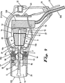
さらに図3A、図3B、および、図4を参照すると、ノーズピース20は音響結合流体15を充填されている。スキャンヘッド106の遠位端部は音響窓125によって密封されており、この音響窓は音響透過性のプラスチックフィルムを備え、および、より詳細に後述される。Oリング17がノーズピース20とピボットフレーム3のノーズ18との間のシールを形成する。ゴム製のシールダイアフラム19がノーズ18とピボットフレーム3との間に配置されており、流体密シールを形成する。シールダイアフラム19内のピボット管6のための穴がピボット管よりも小さく、および、シールダイアフラム19が組立中にピボット管6上に配置される時に密封シールを形成するので、別の流体密シールがシールダイアフラムとピボット管6との間に形成される。動作中は、シールダイアフラム19は屈曲し、流体密シールをそのシールダイアフラム9とピボット管6との間に維持しながらピボット管6が前後に振動することを可能にする。シールダイアフラム19の屈曲の度合いを小さくするために、このシールダイアフラム19は、概ねピボット管6のピボット点付近においてそのピボット管6に接触する。ヨーク7は、このピボット点を跨いでシールダイアフラム19を通り越える。例えばバヨネットタイプのロック機構を含むロッキングプレート34がノーズピース20の背面上に配置されている。ノーズピース20がノーズ18上に配置される時に、2つのねじ34aの頭部がロッキングプレート34内の穴を貫通する。一方向の約10度の回転が、ねじ34aの軸部がロッキングプレート34内の短い湾曲したスロットの中を移動して、図に示されているようにねじ34aの頭部を閉じ込め、ノーズピース20をスキャンヘッドピボットフレーム3にロックすることを引き起こす。この動作を単純に逆転させることによってノーズピース20が取り外されることが可能であるということに留意されたい。充填口35が、ノーズピース20内の中空空洞15に音響流体を最初に充填するために、および、出現する可能性があるあらゆる気泡を取り除くために空洞15に定期的にアクセスするために使用される。
Still referring to FIGS. 3A, 3B, and 4, the
再び図3A、図3B、および、図4を参照すると、トランスデューサアセンブリ124はピボット管6の遠位端部に取り付けられ、流体密シールを形成する。動作中は、トランスデューサ8の遠位面が、音響窓125から定距離(非限定的な例としては、0.5mmから1mm)のままである。トランスデューサ8に信号を搬送しおよびトランスデューサ8から信号を搬送する同軸電気ケーブル8aがピボット管6の中心を通って延び、および、ピボット軸の付近のスロット6aを通って外に出て、したがって同軸ケーブル8aの動きを最小限に保つ。スロット6aと近位端部における成端点すなわち小さなプリント配線基板(PWB)23との間に位置している同軸ケーブル8aの弛んだ長さ部分が、動作中の相対運動を吸収する。このために、同軸ケーブル8aと同軸ケーブル14は、長期の屈曲寿命を有するように作られている。例えば、ケーブル8a、14は、可とう性を強化するように、小さい直径(約1mm)と細い導体とを使用して作られることが可能である。PWB 23は、トランスデューサ8から到着する信号のための前置増幅器を含み、および、2つのホールセンサ13からの信号、電力、および、接地線のための終端点として機能する。PWB 23は、さらに、ケーブルキャップ33とエンコーダケーブル25aとを通過してスキャンヘッド106の中に入るワイヤ21を受け入れる。
Referring again to FIGS. 3A, 3B, and 4, the
図3A、図3B、および、図4を参照すると、図6にも番号10として組み合わせた形で示されているロータ巻線10a、10bと、エンコーダコードトラック12と、ホールセンサ駆動磁石13とのすべてが、ピボット管6の近位端部に接着されている。特に、中間支持構造27が、ロータ巻線24を支持するための軽量かつ硬質の芯を形成する、例えば薄い(0.1mm)エポキシガラス基板とエンコーダコードトラック12との間にサンドイッチされている、硬質のポリエチレン発泡体で形成されることが可能である。
Referring to FIGS. 3A, 3B, and 4, the
図3Bと図4とを参照すると、裏当て鉄板2、2aが側部プレート1a、1bの内側表面に取り付けられている。界磁石28、28aがそれぞれに裏当て鉄板2、2aに接着されている。界磁石28、28aは、対向面に対して垂直なその薄さ方向に磁化されている。各々の磁石28、28aは4つの磁極を有する。各面の一方の半分がN極であり、他方の半分がS極である。ロータアセンブリ5は、2つの磁石28、28aの間のギャップの中を前後に移動する。磁石28のS極は磁石28aのギャップを挟んでN極に対向する。磁石28のN極は磁石28aのS極に対向する。互いに反対方向に極性が与えられている互いに対向する磁石28、28aの間には2つの磁極ギャップが存在する。ロータコイル10の一部分10aが、一方の磁極ギャップの範囲内で振動するように抑制されており、および、別の部分10bが他方のギャップの中で振動する。
Referring to FIGS. 3B and 4, backing
図5を参照すると、この図には、ロータアセンブリ5を含むスキャンヘッド106の分解図が示されている。
Referring to FIG. 5, an exploded view of the
図6を参照すると、トルクモータ130が、限定された角度にわたって、すなわち、約10−14度の角度にわたって旋回軸上でピボット管または支持アーム6を回転させる。トランスデューサアセンブリ124は支持アーム6の一方の端部に連結されており、および、位置エンコーダのコードトラック12はその他方の端部に連結されている。アセンブリ124のトランスデューサ8は、集束超音波ビームがピボット点から離れていく形でピボット管6の縦軸線に沿って方向付けられるように意図されている。ケースとノーズピース20は、トランスデューサ8がノーズピースセクション20内に位置しているように、トルクモータ130と位置エンコーダ128とトランスデューサ8とを取り囲む。ノーズピース20は水(または、超音波を伝導するのに適した他の媒質)で満たされており、トルクモータ130と位置エンコーダ128はシール19のせいで乾燥している。ピボット管6は、ピボット管6が前後に動くことを可能にする可とう性シール19を通り抜ける。音響窓125はノーズピース20の端部に配置されることが可能である。
Referring to FIG. 6, the
スキャンヘッド106内で使用される位置エンコーダ128は、例えば、1ミクロン(μm)の分解能が可能な光学エンコーダである。位置エンコーダ128は、本明細書ではエンコーダコードトラック12と呼ばれている網目状のテープストリップと協働して機能する。位置エンコーダ128は、エンコーダコードトラック12上の網目がその位置エンコーダ128に関連したセンサを通過する時に、この網目の通過をカウントするために、光センサを使用する。このセンサは、ピボット管6の近位端部150の両方の移動方向を検出し、および、1ミクロンの範囲内でピボット管6の遠位端部152の移動位置を追跡することが可能である。
The position encoder 128 used in the
再び図6を参照すると、エンコーダコードトラック12は、ピボット管6のピボット点154から既知の半径方向距離において、スキャンヘッド106のピボット管6の後部に連結されることが可能である。エンコーダコードトラック12は、ピボット管6によって描かれる弦に対してそのエンコーダコードトラック12がどんな位置でも接線方向にあるような半径を有する高精度の表面に取り付けられている。ピボット管6が旋回するにつれて、エンコーダコードトラック12が位置エンコーダ128内の光センサの下を前後に通過する。その結果が、エンコーダコードトラック12が固定されている半径におけるピボット管6の遠位端部152の位置の数値化である。位置情報が、ピボット管6の他方の端部上のピボット点から同一の半径方向距離に位置しているトランスデューサ8の位置を求めるために使用されることが可能である。ピボット点154から測定された近位端部150と遠位端部152の互いに異なる距離も、必要に応じて使用されることが可能である。位置エンコーダ128とピボット管6の近位端部150との間の光結合が、位置エンコーダ128とトランスデューサ8からの回路102とによって発生させられる電子ノイズの伝達を減少させる。
Referring again to FIG. 6, the
トランスデューサ8は、高周波数単一エレメント集束ピエゾ電気超音波トランスデューサであることが可能であり、周波数は30MHzよりも高く、および、約40MHzであることが可能である。トランスデューサ8はRF電気パルス104を入力として受け取り、回路102の動作の送信段階中に出力として超音波音響パルス104を発生させる(図1Aと図1Bとを参照されたい)。これとは逆のプロセスが、トランスデューサ8に対する入力が、データ110によって表されている無線周波数電気信号にトランスデューサ8によって変換される超音波音響パルス104であるように、受信段階中に行われる。スキャンヘッド106内で使用されるトランスデューサ8は、空洞15内の音響媒質に対する適切な音響的整合を確実なものにするように製造された広帯域トランスデューサ8であることが可能である。
Transducer 8 can be a high frequency single element focused piezoelectric ultrasonic transducer, with a frequency higher than 30 MHz and can be about 40 MHz. Transducer 8 receives RF
ピボット管6は、そのピボット管6がその中点154を中心に旋回するように軸受アセンブリ4によって固定されている超軽量のステンレススチール管であることが可能である。トランスデューサ8はピボット管6の一方の端部に連結されており、一方、エンコーダコードトラック12はピボット管6の他方の端部に連結されている。このピボット管6は、軸受アセンブリ4とエンコーダコードトラック12との間にトルクモータ130のコイルを収容し、それによってトルクモータ130の一体的部分を形成する。管材料で形成されているピボット管6は、さらに、トランスデューサ同軸ケーブル8aのための導管としても機能する。
The pivot tube 6 can be an ultralight stainless steel tube that is secured by the bearing assembly 4 such that the pivot tube 6 pivots about its
図7を参照すると、ピボット軸軸受4は、1対のボールベアリングと、ピボット管6を保持する軸外しクランプすなわち片寄りクランプ146とを含む。片寄りクランプ146は、ケーブル8aの配線のために、および、ピボット管6に対する機械的な取り付けおよび取り外しのために、ピボット管6のピボット点がアクセス可能な状態のままであることを可能にする。軸受4は、ピボット点154を中心とした高度に反復可能な一軸回転を確実なものにするために、高精度の軸受と正確に機械加工された構成要素とを有する形に製造されることが可能である。片寄りクランプ146は、その一方の端部においてピボット管6に連結されており、および、その他方の端部においてピン148を介してピボット点154に取り付けられている。
Referring to FIG. 7, the pivot shaft bearing 4 includes a pair of ball bearings and an off-axis or offset
可とう性シール19がピボット管6の中点に取り付けられることが可能であり、および、ノーズピース20のバヨネット迅速着脱アセンブリの後部がロッキングプレート34と2つのねじ34aとを備える。シール19は、ピボット管6とノーズピース20との間に流体密シールを形成するように締め付け固定されているエラストマー膜で作られることが可能である。シール19は、乾燥状態のままであるハウジングの残り部分から流体充填されたノーズピース20を隔離する。
A
2つのホールセンサ13が、そのそれぞれのセンサ13を通過するピボット管6の移動を検出するように、スキャンヘッド106のハウジングの中に配置されている。これらのセンサ13は、トルクモータ130の最大安全作動量において信号を生じさせるように配置されている。リミットスイッチ13が、そのシステムをゼロ偏差、定位置、すなわち、平常位置に戻すために使用されることが可能であるように、そのリミットスイッチ13もピボット点154を中心として互いに対称に配置されている。
Two
ノーズピース20内の中空の空洞15が流体で満たされることが可能である。ノーズピース20は、音響窓125が取り付けられることが可能な取付構造を提供する。ノーズピース20は、流体が中を通して空洞15に加えられるかまたは空洞15から取り除かれてよい充填口35としての排出/充填ねじを特徴とする。ノーズピース20は、流体密シールを確保すると同時に道具を必要とせずにそのノーズピースが迅速に取り外されて取り替えられることを可能にする、バヨネット型迅速着脱アセンブリの一部分を含むことが可能である。
The
音響窓125は、空洞15内の流体に対して適切に音響的に整合している材料の薄膜を含む。この音響窓15は、トランスデューサの移動の全長(例えば、約0.5mmから約1mm)にわたってトランスデューサ8の表面に対して近接しておりかつ垂直のままであるような位置に保持されることが可能である。音響窓を形成する材料は、既知のバルク音響特性に基づいて最初に選択または拒否された。この膜は、例えば1.5 megarayleのような1.3megaRayleから1.7megaRayle(MRayle)の範囲内の音響インピーダンスを示すように選択されることが可能である。この薄膜が取り付けられる方法のような機械的な制約条件が、音響窓125としての使用に関する音響インピーダンスとその結果として生じる適合性とに影響する。音響窓を形成することが可能な材料は、約0.9μmから約4.5μmの範囲内の厚さのポリエステルフィルム、5μm、10μm、15μm、25μmの厚さのポリテトラフルオロエチレン(PTFE)、15μm、25μm、50μmの厚さの低密度ポリエチレン(LDPE)、2μmの厚さのポリカーボネート、4μmの厚さのポリプロピレン、60μmの厚さのラテックスエラストマー、および、25μmの厚さのシリコーンエラストマーを含み、音響窓125を形成する膜に対する超音波ビームの入射角を90度から110度に変化させることを含む様々な構成において試験された。これらの材料と厚さは、30−40MHzのトランスデューサ周波数に関して使用された。周波数が増大するのにつれて、より薄い膜が使用されることが可能だった。さらに、封入された結合流体が、音響窓125の膜との音響的整合を改善するために変更されることが可能だった。例えば、エチレングリコール、トリエチレングリコール、水、軽パラフィン油、および、様々なグリコール水溶液が使用されることが可能である。結合流体としての水と、厚さ25μmのLDPE膜とが、音響窓125のための膜として使用されることが可能である。さらに、厚さ5μmまたは厚さ15μmのPTFEで形成された音響窓125が設けられる。これに加えて、薄いシリコーンエラストマーも、音響窓125を形成する膜のために提供されることが可能である。音響窓125は、ノーズピース20とスキャンヘッド106の外部環境との間の流体密シールを維持する。したがって、高周波数超音波トランスデューサ8と共に使用される音響窓125は薄く、および、空洞15内の流体の音響インピーダンスに非常に近い音響インピーダンスを有する材料で構成されることが可能である。
The
エレクトロニクス回路102は、低ノイズRF前置増幅器と、スキャンヘッド106に対する独自の高忠実度保護回路との両方を提供する。このエレクトロニクス回路102は、トランスデューサ8を駆動するために使用される高エネルギーパルス104から受信サブシステム120内の高感度の受信機器を保護する。低ノイズ前置増幅器は、最小限の歪みしか伴わずにトランスデューサ8の信号を増強する。
The
再び図3A、図3B、および、図4を参照すると、スキャンヘッド106の動作中に、直流(DC)電圧信号が同軸ケーブル14を通してロータコイル10を通して印加される時に、ロータコイル部分10a内とロータコイル部分10b内で電流によって発生させられるローレンツ力が同一の符号で作用し、印加電圧の極性に応じてロータアセンブリ5がピボット軸受4を中心として時計回りまたは反時計回りに回転することを引き起こす。スキャンヘッド106が起動されると、ロータアセンブリ5をその移動範囲の一方の終端に向けて駆動するために、DC電圧信号がロータコイル10に印加される。ロータアセンブリ5が動程の終端に達する前に、ホールセンサ13が、その動程の各終端に1つずつ側部プレート1a、1bに固定されている2つのホールセンサ磁石26、26aの一方をトリガする。制御サブシステム127は、ロータに供給される電圧の極性を反転させることによって応答し、他方のホールセンサ13がトリガされるまでロータアセンブリ5を反対方向に駆動する。この間はずっと、位置エンコーダ128がエンコーダコードトラック12を読み取り、および、ホールセンサ13によって示された2つの動程終端事象(end−of−travel event)に対するトランスデューサ8の相対的な位置を求める。その次に、制御システムは、どんな経路または速度プロファイルがコントローラの中にプログラムされていようとも、位置フィードバックのために位置エンコーダ128からの信号を使用して、トランスデューサ8を前後に駆動することが可能である。
Referring again to FIGS. 3A, 3B, and 4, during operation of the
例えば、Mモードとドップラーが、スキャンヘッド106が適合している2つの他の動作モードである。これらのモードのどちらでも、ロータアセンブリ5は、一般的には、入力コマンドのための人間機械インタフェース136に組み合わされているジョイスティックを使用するオペレータの操作によって、定位置へと電気的に駆動される。オペレータ(図示されていない)が、定期的に更新される、表示装置116上の時間的に静止した画像または一連の画像を目視し、および、トランスデューサ8が向いている方向を操作することが可能である。トランスデューサ8が向いている方向の電子的な表現144(図1A)が、表示装置116上の超音波画像の上に表示されることが可能であり、および、視覚的フィードバックのために使用されることが可能である。組織の診断撮像のためには、超音波の伝搬経路が、組織の音響インピーダンスに非常に近い音響インピーダンスを有する水または他の流体の内部に完全に入っているべきである。空気ギャップ、または、音響インピーダンスの非整合を生じさせる伝搬経路中に位置した材料が、不要な反射の原因となる可能性があり、この不要な反射は、表示装置116上の画像の中の人工物として現れる。一般的に、水に非常に類似した音響特性を有するカップリングゲルが、スキャンヘッド106と撮像対象の組織との間で使用されることが可能である。
For example, M mode and Doppler are two other modes of operation with which the
さらに、位置エンコーダ29およびエンコーダコードトラック12と連携するトルクモータ130はクローズドループで動作する。これらはサーボモータとして作動し、および、ピボット軸受4によって所定の位置に固定されることが可能なピボット管6が制御された仕方でピボット軸154を中心として前後に回転するように、プロセッサ134に関連したモータ制御システムによって制御される。トランスデューサ8は、エンコーダコードトラック12とは反対側のピボット管6の端部に固定されることが可能である。ピボット管6はトランスデューサ8を動かし、トランスデューサ8は、流体充填ノーズピース20内を前後にスキャンさせられる。トランスデューサ8の位置は1ミクロンの範囲内で常に知られている。トランスデューサ8は、回路102を介して受信されて増幅された後にプロセッサ134に送られる超音波情報を送信/受信する。設計の軽量で精密な性質によって、このプロセスは15Hzで行われることが可能であり、このことが表示装置116における画像データ110の表示のためのリアルタイム画像の生成を可能にする。トランスデューサ8を15Hzの周波数で動作させることは、トランスデューサ8の動作範囲内のそのトランスデューサ8の2つのスイープが1ヘルツに等しいので、30フレーム/秒のフレームレートに等しい。さらに、トランスデューサ8の振動周波数が、フレームレートを増大させるために増大させられることが可能である。さらに、トランスデューサによって送信される超音波エネルギーの周波数に応じて、超音波システム131は、30ミクロンよりも小さい空間分解能を有する画像を提供する。例えば、約25MHzの周波数では、空間分解能は約75−100ミクロンである。トランスデューサ周波数が増大するのに応じて、空間分解能が向上する。40MHzから60MHzの範囲内の高いトランスデューサ周波数では、空間分解能は30ミクロンを超えるだろう。トランスデューサの高い動作周波数と、約1μmの精度でのトランスデューサの高精度の機械的位置決めとが、30μmを越える空間分解能を有するリアルタイム超音波画像を超音波システム131が提供することを可能にする。
Further, the
さらに、スキャンヘッド106は、手持ちでの使用、または、固定具上での使用のために設計されることが可能である。スキャンヘッド106は、さらに、水浴中の浸水型スキャナとしても使用されることが可能であり、または、スキャンされるべき組織に対してゲルによって結合されることが可能である。これらの状況では、音響窓125の膜は取り除かれてもよい。
Further, the
要約すると、スキャンヘッド106は、トランスデューサ8と撮像される被写体108との間の良好な音響結合を維持しながら扇形の円弧の形に超音波トランスデューサ8を振動させる電動ハンドヘルド撮像装置である。位置エンコーダ128は、リアルタイム位置情報を制御システムプロセッサ134に送る。トランスデューサ8が移動するにつれて、位置エンコーダ128からの信号が送信パルス104をトリガし、および、これらのパルス104の間に収集された結果的に得られたデータストリーム110が表示装置116上の視覚的出力を含む電子画像の形で表示されるべき位置を、システムプロセッサ134に通信する。スキャンヘッド106は、30フレーム/秒のフレームレートに相当する15Hzまでおよび15Hzを超えるレートで、制御された形で約10mmの距離にわたって流体環境内でトランスデューサ8を連続的に前後に移動させることが可能である。スキャンヘッド106内の位置エンコーダ128は、1μmの精度でリアルタイムでトランスデューサ8の位置を記録することが可能であり、および、1μmの精度でスキャン領域内の任意の位置にトランスデューサ8を位置決めすることが可能である。スキャンヘッド106は、超音波エネルギーが中を通して撮像される被写体108に向けて送られることが可能な音響窓125を含む。音響窓125は、最小限の減衰および/または反射を伴って高周波数超音波を送信することを可能にする。スキャンヘッド106は、容易に手で保持されるのに十分なコンパクトな大きさであることが可能であり、および、15Hzの機械的ピボット旋回/スキャニング/位置決めシステムによって1μmまでの位置決め精度を実現することが可能である。音響窓125は、60MHzを越える周波数の高周波数超音波エネルギーの送信に適合していることが可能である。スキャンヘッド106は、スキャン平面112に関して約8mm×約8mmの撮像領域において30μmよりも小さい画像分解能を有することが可能である(図1Aを参照されたい)。
In summary, the
スキャンヘッド106は、単一の可動部品と、ピボット管6と、可動コイルタイプの制限角度トルクモータ130とを使用する。非可動の界磁石28、28aが比較的大きく、かつ、ロータ巻線24を横断する非常に高いB磁界を維持する、ネオジム鉄ボロンを非限定的な一例とする高エネルギー生成物で作られているので、トルクモータ130は、少しの消費電流で大きなトルク力を生じさせる。可動コイルタイプのモータを使用することの別の利点が、ロータ質量と回転慣性とが最小化されることが可能だということであり、このことが電力消費と振動との低減に役立つ。40MHz以上で撮像される被写体108内の小さい構造が迅速な移動に関連している場合が多い。したがって、こうした設計は、60フレーム/秒に相当する30Hz以上の動作速度を可能にする。
The
可とう性シール19(図4を参照されたい)は、その可とう性シール19の反対側の要素から空洞15内の流体を隔離する。可とう性シール19は、その可とう性シール19がピボット管6に取り付けられることが可能な箇所をピボット軸受4が跨ぐことを可能にするために、片寄りクランプ140を使用することによってロータアセンブリ5のピボット点154の付近に配置されることが可能であり、このことが可とう性シール19上の応力を最小化するのを促進する。可とう性シール19の取り付けは、可とう性シール19内の穴とピボット管6との間の単純な摩擦ばめによって実現されることが可能である。可とう性シール19は、高い疲労寿命を有するポリウレタンエラストマーで作られることが可能である。
A flexible seal 19 (see FIG. 4) isolates the fluid in the
音響流体中に沈められているピボット管6の一部分と、全体的に沈められていることが可能なトランスデューサ8とが、中性浮力があるように設計されることが可能である。動作中は、中性浮力が、そうでない場合にトランスデューサ8とピボット管6との動きの結果として生じる可能性がある振動を打ち消すのを促進することが可能である。実際に、本発明の別の実施形態では、ピボット点154の両側の振動機構全体が中性浮力を有するように調整されることが可能であり、および、音響流体内に完全に沈められている形で動作する。このことが、そうでない場合にオペレータと被写体108とに伝達されることなる振動の概ねすべてを取り除くのに役立つ。
A portion of the pivot tube 6 that is submerged in the acoustic fluid and the transducer 8 that can be submerged entirely can be designed to have neutral buoyancy. During operation, neutral buoyancy can help counteract vibrations that might otherwise occur as a result of movement of the transducer 8 and pivot tube 6. Indeed, in another embodiment of the present invention, the entire vibration mechanism on either side of the
さらに、ノーズピース20は、オペレータによる容易な取り外しと交換とが可能である。ノーズピース20の容易化された取り外しと交換とが、壊れた音響窓125または汚染した音響空洞の交換を容易にする。ノーズピース20が取り付けられる時に最初に音響流体を空洞15に充填するために、および、使用によって音響流体中に気泡が生じる場合にその気泡を追加の流体と入れ替えるために、充填口がノーズピース20の側に設けられることが可能である。単純なバヨネット型のねじりロックが、ノーズピース20をスキャンヘッド106の本体に固定するために使用されることが可能である。特定の用途においてそうであるように、ノーズピース20が無菌でなければならない場合には、ノーズピース20が使い捨てであることが可能である。こうした交換可能なノーズピース20の不可欠な部品が、射出成形プラスチック部品であることが可能な、ノーズピースの基部にヒートシールされているかまたは他の形で取り付けられている、薄いプラスチックで作られた無菌のドレープ(drape)またはシース(sheath)であることが可能である。スキャンヘッド106は、さらに、必要に応じて音響窓125が取り外された形で作動させられることが可能である。
Further, the
図8を参照すると、スキャンヘッド106は、必要に応じて、適切な可とう性シール19によってアーム6の往復移動を可能にするように設計されることが可能である。可とう性シール19は、必要に応じて、アコーディオン設計であることも可能である。
Referring to FIG. 8, the
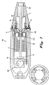
スキャンヘッド106の別の実施形態が図9と図10に示されている。参照番号206を使用して示されているスキャンヘッドのこの実施形態は、上述の説明から理解される上述の実施形態の構成要素に機能において類似している多くの構成要素を有する。スキャンヘッド206は、スキャンヘッド206の構成要素のすべてを支持することが可能なシャーシ215を含む。回路基板224がスキャンヘッド206の中に一体化されている。シャーシ215は、歪み解放クランプ基部225aと、歪み解放クランプ225bと、シャーシ215の近位端部においてケーブルアセンブリ226bを確実に保持するための歪み解放226aとを支持する。ケーブルアセンブリ226bは回路基板224上の電気コネクタ229a、229bに接続する。回路基板224は、モータ制御要素と位置監視回路とを含み、および、超音波システム131内のトランスデューサと処理要素との間でRF信号を通信する(図1Bを参照されたい)。
Another embodiment of the
シャーシ215はピボットフレーム208を支持し、一方、このピボットフレーム208は、シャーシ215の遠位端部において電機子240(図11)に取り付けられているヨーク212を支持する。電機子240は、図11を参照してさらに詳細に後述される。
バヨネット型のロックプレート205aが、ピボットフレーム208に装着されているノーズ205の上の固定具と連結する。ロックプレート205aは着脱自在なノーズピース201aに取り付けられている。ノーズピース201aは、その一方の端部に取り付けられている膜201bを含む音響窓を有する。ノーズピース201aは結合流体空洞201cを取り囲む。ノーズピース201aとロックプレート205aとを含むアセンブリが、バヨネット型のロックシステムを介してスキャンヘッド206上に取り付けられている。
A bayonet-
結合流体空洞201cはトランスデューサ202aを取り囲み、および、トランスデューサ202aは支持アーム203に取り付けられている。トランスデューサ202aはトランスデューサ同軸ケーブル202bに接続されており、トランスデューサ同軸ケーブル202bの反対側の端部は回路基板224に接続されている。ノーズピース201aは、結合流体で結合流体空洞201cを満たすための充填口を含む。充填口は充填口ねじ204で密封されている。成形ゴムシール207が支持アーム203上に取り付けられており、および、流体空洞201cとピボットフレーム208との間に配置されている。
A
軸受予荷重ねじ209と、精密ラジアルボールベアリング208aと、固定用ねじ210aとを含む軸受アセンブリが、小さい半径方向の抗力と実質的にゼロの半径方向または軸方向の遊びとを伴って、電機子アセンブリ240をピボットフレーム208に固定する。支持アーム203を跨いでおりかつロータ接着ピン214によってロータ218に固定されているヨーク212が備えられている。
A bearing assembly that includes a
図12に示されているスキャンヘッド206の部分アセンブリ250が、背部裏当て鉄板216aと、1対の裏当て鉄柱227a、227bと、背部界磁石217aとを含む。磁石ワイヤコイル218bが、トルクモータの電機子を形成するためにロータ218の周りに巻き付けられている。光学エンコーダコードトラック219が、トルクモータの動きに対してすべての箇所で接線方向にあるようにロータ218の一方の端部に取り付けられている。光学エンコーダ読み取りヘッド220が、図12に示されているように、エンコーダ調整スライド223aに固定されている。エンコーダ調整スライド223aがスライドして、電機子240に固定されているエンコーダコードトラック219に対して相対的に光学読み取りヘッド220を調整することが可能であるように、エンコーダ調整スライド223aはシャーシ215に嵌合させられている。この動きは高精度でかつ制御されており、および、エンコーダ読み取りヘッド220が、そのエンコーダ読み取りヘッド220において最大の信号強度が得られるように最適の位置にある時に、読み取りヘッド調整スライド223aが読み取りヘッド止めねじ223cによって所定の位置にロックされる。光学エンコーダが集束させられているので、この光学エンコーダは反射性のエンコーダコードトラック219から既知の距離に位置合わせされることが可能である。この距離は最大のエンコーダ信号に対応する。読み取りヘッド調整ねじ223bに連結されているコイルばね223dがバックラッシュの防止に役立つ。エンコーダコードトラック219と組み合わされている光学読み取りヘッド220が、1μmの精度で電機子240の位置が記録されることを可能にする。シャーシ215に対する電機子240の絶対位置を求めるために、および、電機子240の行程超過を防止するために、1対の光学リミットスイッチ221aが回路基板224上に備えられている。ロータ218に取り付けられている反射性表面221bが光学リミットスイッチ221aから信号を反射する。
The partial assembly 250 of the
図9と図10とに示されているように、シャーシ215は迅速解除強固取付ジャック(quick release hard mount jack)222aを含む。この機構は迅速解除アセンブリの一部分であり、この迅速解除アセンブリについては、図13と図14を参照してさらに詳細に後述する。
As shown in FIGS. 9 and 10, the
ケース頂部233と、ケース底部234と、ケースガスケット228とを含むケースが、スキャンヘッド206の内部構成要素の周囲の流体密シールを実現する。ケース頂部233とケース底部234とケースガスケット228は、RF遮蔽を改善するために導電性被覆物251で被覆されている。
A case including a
図11を参照すると、電機子240と、支持アーム203と、トランスデューサ202aと、成形シール207とが、より詳細に示されている。電機子240は精密機械加工された構成要素から作られることが可能であり、このことが、上述の実施形態で使用される複合構造に比較して、量産性を向上させ、コストを低減させ、性能を改善する。支持アーム203は着脱可能であり、および、支持アーム取付台213と2つの段付きボルト231a、231bとによって取り付けられることが可能であり、これらの段付きボルト231a、231bはヨーク212とロータ218との中の精密穴の中に配置されている。したがって、破損したトランスデューサ202aおよび/または成形シール207は、電機子240全体を交換することなしに交換されることが可能であるということが理解されるだろう。
Referring to FIG. 11, the
エンコーダコードトラック219は、ばね鋼基体から作られている。エンコーダコードトラック219は、そのエンコーダコードトラック219を事前に折り曲げることを避ける技術を使用して取り付けられることが可能である。この事前折り曲げはエンコーダコードトラック219に損傷を与える可能性がある。2つのエンコーダコードトラック保持器230aがその各端部においてエンコーダコードトラック219を保持し、ばね鋼がロータ218の正確な湾曲を描くように強制する。エンコーダコードトラック保持器230aは、ねじ230bを使用して所定の位置に固定されている。この代わりに、軽量の糸がねじ230bの周りに結びつけられて、例えば接着剤を使用してエンコーダコードトラック219の端部に接着されてもよい。
The
この実施形態のスキャンヘッド206は、22度以上のスイープ角度を与える。このスイープ角度は、ホールセンサ13と2つのホールセンサ磁石26、26aとリミットスイッチ221aとによって画定されるトランスデューサ202aの動きを意味する。着脱自在な支持アーム203によるスイープ角度の増大に加えて、製造中、または、現場での点検修理中といった製造後に、異なる撮像要件に適応するように支持アーム203の長さが変更されてもよい。支持アーム203は、トランスデューサ202aがエンコーダコードトラック219よりもピボット点154から約20%より遠く離れているような長さであることが可能である(図9を参照されたい)。この構成が、トランスデューサ202aにおいて測定される15mmを越えるスキャン幅を実現する。
The
この実施形態におけるスキャンヘッド206は剛体のシャーシ215上にアセンブリされている。このスキャンヘッド206は、ケース233、234なしで所定の位置で試験が行われることが可能であるように、シャーシ215上で機能性を完全なものにするようにアセンブリされることが可能である。したがって、シャーシ215の設計は、ワイヤ配線と歪み解放との確認、電気的な検査、光学エンコーダ読み取りヘッド220の調整、および、リミットスイッチ221aの機能検査を可能にする。
The
図13と図14を参照すると、迅速解除強固取付がより詳細に示されている。この迅速解除機構は、スキャンヘッド206を迅速に着脱するために、ばね式バヨネット止め具を使用する。迅速解除強固取付プラグ222bが、迅速解除強固取付ジャック222aの近位にある端部に位置決めピン222cを含む。強固取付プラグ222bは、位置決めピン222cに隣接した迅速着脱式の上部機能222dと、位置決めピン222cに隣接したコイルばね222fとを含む。位置決めピン222cは、スキャンヘッド106が正確な90度の増分で取り付けられ、および、再取り付けられることを可能にする。図14に示されているように、保持リング222eが、強固取付ジャック222aに取り付けられている時に、強固取付プラグ222bに押し当たる。
Referring to FIGS. 13 and 14, the quick release firm attachment is shown in more detail. This quick release mechanism uses a spring bayonet stop to quickly attach and detach the
図15を参照すると、ノーズ205がより詳細に示されている。このノーズ205はガスケット突起206bを含み、このガスケット突起206bは、ノーズ205とピボットフレーム208との間で成形シール207(図11)を締め付ける時に、その成形シール207に対する損傷を防止する。シール207は、柔軟な可とう性のエラストマーで作られることが可能である。この成形形状は中央に位置した休止位置を与え、および、動作中におけるシール207の引張りモードの変形を排除する。これとは対照的に、平らなシールは動作中に曲げと引っ張りの両方を受け、その結果としてモータ上に2つの異なった荷重を生じさせるが、これは補正が困難である。成形シール207は、自動車のギアシフト上のシフターブーツ(shifter boot)のように設計されることが可能である。この成形シール207は曲げ変形だけしか受けず、このことはモータ上のより小さくかつより均一な荷重を結果的に生じさせる。
Referring to FIG. 15, the
スキャンヘッド206は、モータ制御機能と位置監視機能とRF信号送受信とを統合する一体型の回路基板224を含む。これに加えて、回路基板224は光学リミットスイッチ221aを収容する。回路基板224は予め作られて試験されることが可能である。この回路基板224は、ピボット点のほぼ上方に接続点を配置することによって、トランスデューサ同軸ケーブル202bとモータワイヤ232との配線がモータ上で最小限の抗力で行われることを可能にする。
The
ケース233、234は無荷重軸受であることが可能であり、スキャンヘッド206の純粋に保護的な部品であることが可能である。このケースはスキャンヘッド206の内部構成要素を防水処理して、これらの内部構成要素が汚染しないように保つのに役立つ。ケース233、234は、ねじによってシャーシ215に固定されることが可能である。この代わりに、そのケースの2つの半分部分233、234は、スキャンヘッド206を改ざん防止性および耐水性にするために、互いに接着させられるか、または、他の形で互いに付着させられてよい。
ノーズピース201aは使い捨ての音響窓を含んでもよい。図17A、図17B、図18、図19A、図19B、図20、図21、図22、および図23を参照すると、ノーズピース320と音響窓330の構造が示されている。音響窓330は、上述の音響窓125に類似している。ノーズピース320は、流体を受け入れるための充填口322を含む。ノーズピース320は、取り付けられている時に音響窓330に近接している端部に肩部324を有する。凹み326とリップ(lip)328とが、音響窓330とのスナップ嵌めを形成するように、肩部324に隣接して配置されている。
The
図17Bは、採用随意の囲い板340が取り付けられているノーズピース320を示す。この囲い板340は、液体または生物学的材料による汚染からノーズピース320とスキャンヘッド206とを保護するために、音響窓330に取り付けられている。
FIG. 17B shows the
図21に示されているように、音響窓330は、ノーズピース320内のリップ328と相補形の形状を有する溝332を含む。
As shown in FIG. 21, the
音響窓330は、様々な要求の厳しい環境において高周波数高分解能超音波プローブを封入するという特定の課題を克服するように設計されることが可能である。音響窓330は、音響性能を過度に損なうことなしに、トランスデューサを保護しかつ無菌環境内で撮像を可能にするための安価な手段を提供する。音響窓330は、流体密の機械的スナップオン取付構造を含む成形プラスチックフレームから構成されることが可能である。この音響窓330は、永久機械加工ノーズピースの上に「スナップ嵌合」してプローブの流体充填封入ノーズを形成する、成形された使い捨て要素であることが可能である。音響窓をノーズピースに着脱するためには道具は不要である。例えば、音響窓の形状が、単純な転がり運動を使用するトランスデューサのノーズピースに対する取付けを可能にする。音響窓は、覆われるべきノーズピースに応じて任意の形状であることが可能である。超音波透過性材料の薄膜が、フレーム350の前面に取り付けられることが可能な膜352を形成する。フレーム350と膜352とが音響窓330を構成する。
The
音響窓の膜を形成する材料の特性と厚さが、封入されるべき特定のプローブの特性に適合するように選択される。例えば本明細書に参考として内容全体が組み入れられている米国特許第5,479,927号、同第5,983,123号、および、同第6,574,499号に開示されている超音波透過性材料のような超音波透過性材料が、音響窓330の膜352を形成するために使用されることが可能である。一側面では、この超音波透過性材料はポリエステル、ポリカーボネート、アクリル(acrylic)、熱可塑性エラストマー、または、シリコーンエラストマーであることが可能である。超音波透過性材料の例は、非限定的に、E.I.Du Pont de Nemours and Company,Wilmington Del.から入手可能なSurlynTM(登録商標)8940およびKaptonTM(登録商標)のようなSurlynTM(登録商標)イオノマーと、Mitsui & Co.,Tokyo,Japanから入手可能なTPXTM(登録商標)MX−002、TPXTM(登録商標)95、および、MX−004のようなポリメチルペンテンと、TeflonTM(登録商標)、MylarTM(登録商標)、低密度ポリエチレンのようなポリエチレン、ポリカーボネート、ポリプロピレン、および、様々なポリウレタンのフィルムとを含む。一実施形態では、超音波透過性材料は特定の厚さに押出成形され、および、流体密のシールを形成するために音響窓330のフレーム350に熱溶接されることが可能である。膜352の厚さは、選択される超音波透過性材料に応じて様々だろう。一側面では、膜352は25μm以下の厚さを有する。別の実施形態では、膜352の厚さは1μmから25μmの範囲内であることが可能である。膜352をフレーム350に封着するために使用される方法は、選択される超音波透過性材料に応じて様々だろう。膜352をフレーム350に封着する方法の例は、非限定的に、接着剤、溶接技術(例えば、RF溶接、超音波溶接、および、熱溶接)、および、メカニカルシールを含む。
The properties and thickness of the material forming the acoustic window membrane are selected to match the properties of the particular probe to be encapsulated. For example, ultrasound disclosed in US Pat. Nos. 5,479,927, 5,983,123, and 6,574,499, the entire contents of which are incorporated herein by reference. An ultrasonically transparent material, such as a transparent material, can be used to form the
図20と図21を参照すると、スナップ構造がフレーム350内の溝332を含む。音響窓330が取り付けられるノーズピース320はリップ328を含む。このリップ328は、フレーム330内の溝332に対してわずかにオーバーサイズでありかつネガティブであることが可能である。音響窓330は、リップ328と溝332との間に形成されるシールによって、完全に所定位置にある時に押し込み式の嵌合が得られるように、ノーズピース320上に押し付けられることが可能である。この嵌合は、さらに、溝332とリップ328との締まり嵌めタイプの嵌合によって流体密である。音響窓330をノーズピース320上に嵌合する前に、ノーズピースに結合流体が部分充填されることが可能である。結合流体の例は、非限定的に、水、エチレングリコール、トリエチレングリコール、軽パラフィン油、および、様々なグリコール水溶液を含む。音響窓330を嵌合した後に、気泡が取り除かれて、ノーズピース/音響窓アセンブリが、ノーズピース320の側に配置されている充填口322を経由して結合流体で完全に満たされることが可能である。
Referring to FIGS. 20 and 21, the snap structure includes a
周囲環境からのプローブの完全な隔離を必要とする環境の場合には、音響窓330のシース付きの変型が、プローブ全体にわたってケーブルにまで達する形で嵌合するように設計されることが可能なポリエチレンフィルムのヒートシールされたシース340を含む。このシースは、使い捨ての音響窓330の一部分として形成されることが可能であり、したがって、殺菌が必要な時には窓全体とシースとが取り外されて廃棄されることが可能である。
For environments that require complete isolation of the probe from the surrounding environment, a sheathed variant of the
代案の実施形態では、高周波数高フレームレート超音波撮像システムは、被写体の中に挿入されたシリンジ、カテーテル、または、他の侵襲的な要素を撮像するために使用されてもよい。図24は表示装置116上の画像360を示すスクリーンショットである。この画像は胎児368を含む。胎児368は頭部366と子宮362とを含む。超音波システム131は、針364が胎児368の子宮362の中に入る時にその針364を視覚化して案内するために使用されることが可能である。
In alternative embodiments, the high frequency, high frame rate ultrasound imaging system may be used to image a syringe, catheter, or other invasive element inserted into the subject. FIG. 24 is a screenshot showing an
図25は、高周波数高フレームレート超音波撮像システムの一側面の動作を示す流れ図400である。この流れ図のブロックが、図に示されている順序で、または、図に示されている順序とは異なる順序で、または、同時に実行されてよい。ブロック402では、トランスデューサ8は、少なくとも20MHzの周波数の超音波エネルギーを生じさせる。
FIG. 25 is a
ブロック404では、超音波エネルギーは送信サブシステム118によって被写体114の中に送信される(図1)。ブロック406では、受信サブシステム120が、戻された超音波エコーパルス104を受信し、および、プロセッサ134とスキャンコンバータ129とによる処理のために制御サブシステム127にその受信された超音波を通信する。
In
ブロック408では、表示装置116上の画像を生成するために、受信された超音波が、ソフトウェア123の命令の下でプロセッサ134とスキャンコンバータ129とによって処理される。この画像は少なくとも15フレーム/秒(fps)のフレームレートを有する。
At block 408, the received ultrasound is processed by
高周波数高フレームレート超音波撮像システムを幾つかの特定の具体的な実施形態に関して説明してきたが、本明細書に添付されている特許請求項に概説されている高周波数高フレームレート超音波撮像システムの範囲から逸脱することなしに、これらの実施形態の様々な変更が当業者に明らかだろう。 Although a high frequency high frame rate ultrasound imaging system has been described with respect to some specific embodiments, the high frequency high frame rate ultrasound imaging outlined in the claims appended hereto. Various modifications of these embodiments will be apparent to those skilled in the art without departing from the scope of the system.
Claims (49)
少なくとも20メガヘルツ(MHz)の周波数で超音波を発生し、該発生した超音波の少なくとも一部分を対象に送信し、該対象から超音波エネルギを受信するように構成された単一エレメントの超音波トランスデューサを備えるトランスデューサアセンブリと、
近端部と遠端部を有する細長い部材であって、該細長い部材は、該近端部から離れた旋回軸の周りに旋回するよう構成され、前記トランスデューサアセンブリが前記細長い部材の前記近端部に、回転不能に結合される、細長い部材と、
弓状凸面往復通路に沿って少なくとも7.5Hzの周波数で前記超音波トランスデューサを揺動させる揺動手段であって、該揺動手段が、前記ピボット軸と前記遠端部との間に前記細長い部材に対し固定されたロータ巻線を備え、前記トランスデューサの前記弓状凸面往復通路から離れた、前記弓状凸面往復通路と同一平面にある弓状往復経路に沿って前記ロータ巻線の移動がトランスデューサの相補的逆移動を引き起こすように移動する、揺動手段と、
を備え、
前記トランスデューサの前記弓状凸面往復通路は、前記揺動手段の前記部分の前記弓状凸面往復通路と同一平面にある、超音波画像システムに用いるスキャンヘッド。In a scan head used in an ultrasound imaging system ,
A single element ultrasonic transducer configured to generate ultrasound at a frequency of at least 20 megahertz (MHz), transmit at least a portion of the generated ultrasound to a subject, and receive ultrasound energy from the subject A transducer assembly comprising:
An elongate member having a proximal end and a distal end, the elongated member is configured to pivot about a pivot axis away from said proximal end, the proximal end of the transducer assembly the elongate member to non-rotatably coupled, the elongate member,
Oscillating means for oscillating the ultrasonic transducer at a frequency of at least 7.5 Hz along an arcuate convex reciprocating path, the oscillating means being elongated between the pivot shaft and the far end. A rotor winding fixed to the member, the movement of the rotor winding along an arcuate reciprocation path that is coplanar with the arcuate convex reciprocation path away from the arcuate convex reciprocation path of the transducer; It moves to cause complementary reverse movement of the transducer, and the oscillating means,
With
A scanning head for use in an ultrasound imaging system, wherein the arcuate convex reciprocating path of the transducer is flush with the arcuate convex reciprocating path of the portion of the swinging means .
前記被写体の中に送信される前に発生された超音波の少なくとも一部分が前記膜を貫通して通過できるように前記音響的に透過可能な膜が配置される、請求項2に記載のスキャンヘッド。The enclosed space is defined by a partially acoustically permeable membrane;
The scan head of claim 2 , wherein the acoustically permeable film is disposed such that at least a portion of the ultrasound generated before being transmitted into the subject can pass through the film. .
1秒につき少なくとも15フレーム(fps)のフレームレートを有する画像を提供するため、前記受信した超音波を処理するように構成されたプロセッサと、
を備えたことを特徴とする超音波画像システム。A scan head according to claim 1;
A processor configured to process the received ultrasound to provide an image having a frame rate of at least 15 frames per second (fps);
An ultrasonic imaging system comprising:
1秒につき少なくとも15フレーム(fps)のフレームレートを有する画像を提供するため、前記受信した超音波を処理するように構成されたプロセッサと、
前記弓状凸面往復経路に沿った予め決定した位置の1ミクロン(μm)以内に前記トランスデューサを配置する手段と、
を備えたことを特徴とする超音波画像システム。A scan head according to claim 1;
A processor configured to process the received ultrasound to provide an image having a frame rate of at least 15 frames per second (fps);
Means for positioning the transducer within 1 micron (μm) of a predetermined position along the arcuate convex reciprocating path;
An ultrasonic imaging system comprising:
近端部と遠端部を有する細長い部材であって、該細長い部材は、該近端部及び遠端部から離れた旋回軸の周りに旋回するよう構成され、前記トランスデューサアセンブリが前記細長い部材の前記近端部に、回転不能に結合される、細長い部材と、
ロータ巻線を備えるモータであって、前記ピボット軸と前記遠端部との間に前記ロータ巻線が前記細長い部材に結合しており、前記モータは弓状凸面往復通路に沿って少なくとも7.5Hzの周波数で前記トランスデューサを揺動させるよう構成され、前記ロータ巻線の少なくとも一部分は前記トランスデューサの前記弓状凸面往復通路から離れかつ同一平面にある弓状凹面往復経路に沿って揺動するよう構成される、モータと、
を備えたことを特徴とする超音波画像システムに用いるスキャンヘッド。A single element ultrasonic transducer configured to generate ultrasound at a frequency of at least 20 megahertz (MHz), transmit at least a portion of the generated ultrasound to a subject, and receive ultrasound energy from the subject A transducer assembly comprising:
An elongate member having a proximal end and a distal end, the elongated member is configured to pivot about a pivot axis away from said proximal end and a distal end, the transducer assembly of the elongate member It said proximal end is non-rotatably coupled, the elongate member,
A motor including a rotor winding, said rotor winding is bound to the elongate member between the pivot axis and the distal end, the motor along the arcuate convex reciprocating passage at least 7. The transducer is configured to oscillate at a frequency of 5 Hz such that at least a portion of the rotor winding oscillates along an arcuate concave reciprocating path that is spaced from and coplanar with the arcuate convex reciprocating path of the transducer. Composed of a motor,
A scan head for use in an ultrasound imaging system comprising:
1秒につき少なくとも15フレーム(fps)のフレームレートを有する画像を提供するため、前記受信した超音波を処理するように構成されたプロセッサと、
を備えたことを特徴とする超音波画像システム。A scan head according to claim 45 ;
A processor configured to process the received ultrasound to provide an image having a frame rate of at least 15 frames per second (fps);
An ultrasonic imaging system comprising:
1秒につき少なくとも15フレーム(fps)のフレームレートを有する画像を提供するため、前記受信した超音波を処理するように構成されたプロセッサと、
前記トランスデューサを前記弓状凸面往復経路に沿った所定の位置の1ミクロン(μm)以内に配置するよう構成された位置エンコーダと、を備えたことを特徴とする超音波画像システム。A scan head according to claim 45 ;
A processor configured to process the received ultrasound to provide an image having a frame rate of at least 15 frames per second (fps);
An ultrasonic imaging system comprising: a position encoder configured to position the transducer within 1 micron (μm) of a predetermined position along the arcuate convex reciprocating path.
Applications Claiming Priority (9)
| Application Number | Priority Date | Filing Date | Title |
|---|---|---|---|
| US41716402P | 2002-10-10 | 2002-10-10 | |
| US60/417,164 | 2002-10-10 | ||
| US46895603P | 2003-05-09 | 2003-05-09 | |
| US46895803P | 2003-05-09 | 2003-05-09 | |
| US60/468,958 | 2003-05-09 | ||
| US60/468,956 | 2003-05-09 | ||
| US47023403P | 2003-05-14 | 2003-05-14 | |
| US60/470,234 | 2003-05-14 | ||
| PCT/US2003/032320 WO2004034694A2 (en) | 2002-10-10 | 2003-10-10 | High frequency high frame-rate ultrasound imaging system |
Publications (3)
| Publication Number | Publication Date |
|---|---|
| JP2006502828A JP2006502828A (en) | 2006-01-26 |
| JP2006502828A5 JP2006502828A5 (en) | 2007-01-18 |
| JP4713339B2 true JP4713339B2 (en) | 2011-06-29 |
Family
ID=32097076
Family Applications (1)
| Application Number | Title | Priority Date | Filing Date |
|---|---|---|---|
| JP2005501172A Expired - Lifetime JP4713339B2 (en) | 2002-10-10 | 2003-10-10 | High frequency high frame rate ultrasound imaging system |
Country Status (8)
| Country | Link |
|---|---|
| US (5) | US7255678B2 (en) |
| EP (1) | EP1465531B1 (en) |
| JP (1) | JP4713339B2 (en) |
| AU (1) | AU2003284096A1 (en) |
| CA (1) | CA2501647C (en) |
| ES (1) | ES2402270T3 (en) |
| HK (1) | HK1085109A1 (en) |
| WO (1) | WO2004034694A2 (en) |
Families Citing this family (60)
| Publication number | Priority date | Publication date | Assignee | Title |
|---|---|---|---|---|
| GB2391625A (en) | 2002-08-09 | 2004-02-11 | Diagnostic Ultrasound Europ B | Instantaneous ultrasonic echo measurement of bladder urine volume with a limited number of ultrasound beams |
| US8221322B2 (en) | 2002-06-07 | 2012-07-17 | Verathon Inc. | Systems and methods to improve clarity in ultrasound images |
| US7819806B2 (en) | 2002-06-07 | 2010-10-26 | Verathon Inc. | System and method to identify and measure organ wall boundaries |
| US8221321B2 (en) | 2002-06-07 | 2012-07-17 | Verathon Inc. | Systems and methods for quantification and classification of fluids in human cavities in ultrasound images |
| US7255678B2 (en) * | 2002-10-10 | 2007-08-14 | Visualsonics Inc. | High frequency, high frame-rate ultrasound imaging system |
| US7052460B2 (en) * | 2003-05-09 | 2006-05-30 | Visualsonics Inc. | System for producing an ultrasound image using line-based image reconstruction |
| US8926533B2 (en) | 2003-12-30 | 2015-01-06 | Liposonix, Inc. | Therapy head for use with an ultrasound system |
| US7695437B2 (en) * | 2003-12-30 | 2010-04-13 | Medicis Technologies Corporation | Ultrasound therapy head with movement control |
| US8708909B2 (en) | 2004-01-20 | 2014-04-29 | Fujifilm Visualsonics, Inc. | High frequency ultrasound imaging using contrast agents |
| US7674228B2 (en) | 2004-03-01 | 2010-03-09 | Sunnybrook And Women's College Health Sciences Centre | System and method for ECG-triggered retrospective color flow ultrasound imaging |
| US20050245826A1 (en) * | 2004-03-23 | 2005-11-03 | Gervais Chetley Livingston C | Apparatus for imaging human tissue |
| EP1738407B1 (en) | 2004-04-20 | 2014-03-26 | Visualsonics Inc. | Arrayed ultrasonic transducer |
| US7356905B2 (en) * | 2004-05-25 | 2008-04-15 | Riverside Research Institute | Method of fabricating a high frequency ultrasound transducer |
| EP1776669A1 (en) * | 2004-08-05 | 2007-04-25 | Koninklijke Philips Electronics N.V. | Imaging system |
| WO2006136952A2 (en) * | 2005-03-04 | 2006-12-28 | Visualsonics Inc. | Method for synchronization of breathing signal with the capture of ultrasound data |
| US20060224090A1 (en) * | 2005-03-29 | 2006-10-05 | Isaac Ostrovsky | Apparatus and method for stiffening tissue |
| US20060241461A1 (en) * | 2005-04-01 | 2006-10-26 | White Chris A | System and method for 3-D visualization of vascular structures using ultrasound |
| GB0508250D0 (en) * | 2005-04-23 | 2005-06-01 | Smith & Nephew | Composition |
| US20090149748A1 (en) * | 2005-08-25 | 2009-06-11 | Virginia Commonwealth University | Portable Pulmonary Injury diagnostic Devices And Methods |
| ES2402741T3 (en) | 2005-11-02 | 2013-05-08 | Visualsonics, Inc. | Digital transmission beam shaper for an ultrasonic transducer system with distribution |
| US8275449B2 (en) * | 2005-11-11 | 2012-09-25 | Visualsonics Inc. | Overlay image contrast enhancement |
| US7750536B2 (en) | 2006-03-02 | 2010-07-06 | Visualsonics Inc. | High frequency ultrasonic transducer and matching layer comprising cyanoacrylate |
| US8128568B2 (en) * | 2006-05-02 | 2012-03-06 | U-Systems, Inc. | Handheld volumetric ultrasound scanning device |
| US8183745B2 (en) * | 2006-05-08 | 2012-05-22 | The Penn State Research Foundation | High frequency ultrasound transducers |
| CA2654086C (en) | 2006-06-02 | 2016-05-24 | St. Michael's Hospital | Ultrasonic evaluation of venous structures |
| US20080033292A1 (en) * | 2006-08-02 | 2008-02-07 | Insightec Ltd | Ultrasound patient interface device |
| JP5249218B2 (en) * | 2006-08-09 | 2013-07-31 | コーニンクレッカ フィリップス エレクトロニクス エヌ ヴィ | Ultrasonic imaging system |
| US7891230B2 (en) * | 2007-02-08 | 2011-02-22 | Penrith Corporation | Methods for verifying the integrity of probes for ultrasound imaging systems |
| US20080194963A1 (en) * | 2007-02-08 | 2008-08-14 | Randall Kevin S | Probes for ultrasound imaging systems |
| US20080194960A1 (en) * | 2007-02-08 | 2008-08-14 | Randall Kevin S | Probes for ultrasound imaging systems |
| US20080243035A1 (en) * | 2007-03-26 | 2008-10-02 | Liposonix, Inc. | Interchangeable high intensity focused ultrasound transducer |
| US8167803B2 (en) | 2007-05-16 | 2012-05-01 | Verathon Inc. | System and method for bladder detection using harmonic imaging |
| US8506490B2 (en) * | 2008-05-30 | 2013-08-13 | W.L. Gore & Associates, Inc. | Real time ultrasound probe |
| EP2323559A4 (en) | 2008-08-07 | 2016-09-21 | Verathon Inc | Device, system, and method to measure abdominal aortic aneurysm diameter |
| US7731516B2 (en) * | 2008-09-09 | 2010-06-08 | General Electric Company | Connector system for engaging a portion of a plug within a receptacle |
| US9173047B2 (en) | 2008-09-18 | 2015-10-27 | Fujifilm Sonosite, Inc. | Methods for manufacturing ultrasound transducers and other components |
| US8316518B2 (en) | 2008-09-18 | 2012-11-27 | Visualsonics Inc. | Methods for manufacturing ultrasound transducers and other components |
| US9184369B2 (en) | 2008-09-18 | 2015-11-10 | Fujifilm Sonosite, Inc. | Methods for manufacturing ultrasound transducers and other components |
| DE202008016972U1 (en) * | 2008-12-22 | 2009-03-19 | Asm Automation Sensorik Messtechnik Gmbh | probe unit |
| US8317713B2 (en) | 2009-01-09 | 2012-11-27 | Volcano Corporation | Ultrasound catheter with rotatable transducer |
| US20100292575A1 (en) * | 2009-05-15 | 2010-11-18 | General Electric Company | Device and method for identifying tampering of an ultrasound probe |
| TWI384252B (en) * | 2009-07-01 | 2013-02-01 | Pai Chi Li | Ultrasonic probe |
| CN101988965A (en) * | 2009-07-30 | 2011-03-23 | 建兴电子科技股份有限公司 | Ultrasonic sensing device with function of adjusting signal attenuation time and application method |
| WO2011031753A2 (en) * | 2009-09-08 | 2011-03-17 | Volcano Corporation | Devices, systems, and methods for field of view control in imaging systems |
| DE102009046146A1 (en) * | 2009-10-29 | 2011-05-12 | Robert Bosch Gmbh | Ultrasonic transducer for use in a fluid medium |
| US20110166455A1 (en) * | 2010-01-07 | 2011-07-07 | Cully Edward H | Catheter |
| CN102370497B (en) * | 2010-08-18 | 2016-03-09 | 深圳迈瑞生物医疗电子股份有限公司 | 3D mechanical probe |
| US9255834B2 (en) * | 2011-06-15 | 2016-02-09 | Textron Innovations Inc. | System and method for detecting objects in a fluid system |
| JP2013031151A (en) * | 2011-06-20 | 2013-02-07 | Renesas Electronics Corp | Encryption communication system and encryption communication method |
| WO2014099760A1 (en) | 2012-12-21 | 2014-06-26 | Mai Jerome | Ultrasound imaging with variable line density |
| US9211110B2 (en) | 2013-03-15 | 2015-12-15 | The Regents Of The University Of Michigan | Lung ventillation measurements using ultrasound |
| PT106930A (en) * | 2013-05-03 | 2014-11-03 | Univ Trás Os Montes E Alto Douro | WORKING SURFACE WITH CONTROLLED HEATING AREA FOR BODY TEMPERATURE MAINTENANCE IN ANIMALS |
| US10001948B2 (en) * | 2013-05-13 | 2018-06-19 | Rambus Inc. | Buffer circuit with data bit inversion |
| CN106456111B (en) | 2014-03-12 | 2020-02-11 | 富士胶片索诺声公司 | High frequency ultrasound transducer with ultrasound lens with integrated central matching layer |
| US10592120B2 (en) * | 2014-12-19 | 2020-03-17 | Rambus Inc. | Memory system with threaded transaction support |
| CN108938004A (en) * | 2015-07-13 | 2018-12-07 | 古野电气株式会社 | Probe adapter, ultrasonic imaging apparatus |
| EP3350586A1 (en) * | 2015-09-17 | 2018-07-25 | Consejo Superior De Investigaciones Científicas | Method for detecting circulating cells in superficial body fluids |
| EP3383275B1 (en) | 2015-11-25 | 2021-01-06 | Fujifilm Sonosite, Inc. | High frequency ultrasound transducer and method for manufacture |
| EP3326572A1 (en) | 2016-11-25 | 2018-05-30 | RWTH Aachen University | Intraoral scanning device and method for high-resolution ultrasonic scan and 3d reconstruction of tooth region |
| EP3524160B1 (en) * | 2018-02-07 | 2022-12-21 | Esaote S.p.A. | Ultrasound probe and ultrasound system provided with the said ultrasound probe |
Citations (11)
| Publication number | Priority date | Publication date | Assignee | Title |
|---|---|---|---|---|
| JPS605132A (en) * | 1983-06-23 | 1985-01-11 | 松下電器産業株式会社 | Ultrasonic probe |
| JPS6168034A (en) * | 1984-09-12 | 1986-04-08 | 松下電器産業株式会社 | Ultrasonic probe |
| JPS61119249A (en) * | 1984-11-14 | 1986-06-06 | 松下電器産業株式会社 | Ultrasonic probe |
| JPS61154653A (en) * | 1984-12-28 | 1986-07-14 | 旭光学工業株式会社 | Probe for ultrasonic diagnostic apparatus |
| JPS6315943A (en) * | 1986-07-07 | 1988-01-23 | 松下電器産業株式会社 | Ultrasonic probe |
| JPH021248A (en) * | 1988-03-29 | 1990-01-05 | Toshiba Corp | Mechanical scanning type ultrasonic scanner |
| JPH04319662A (en) * | 1991-04-18 | 1992-11-10 | Toshiba Corp | Ultrasonic probe |
| JPH05176931A (en) * | 1991-12-27 | 1993-07-20 | Olympus Optical Co Ltd | Intracelom ultrasonic diagnostic device |
| JPH05237111A (en) * | 1992-02-28 | 1993-09-17 | Fujitsu Ltd | Ultrasonic probe |
| JPH05509247A (en) * | 1990-08-02 | 1993-12-22 | ベー・ファウ・オプティシェ・インダストリー・“デ・オウデ・デルフト” | Endoscope |
| JP2002017731A (en) * | 2000-07-10 | 2002-01-22 | Matsushita Electric Ind Co Ltd | Three-dimensional drive motor device, and ultrasonic vibrator drive motor device and ultrasonograph using the same |
Family Cites Families (145)
| Publication number | Priority date | Publication date | Assignee | Title |
|---|---|---|---|---|
| US3886490A (en) | 1973-05-25 | 1975-05-27 | Stanford Research Inst | Apparatus for coupling an array of ultrasonic transducers to an ultrasonic compressional image field and scanning the image field |
| US3955561A (en) | 1974-09-16 | 1976-05-11 | Indianapolis Center For Advanced Research, Inc. | Cardioscan probe |
| US3974826A (en) | 1974-09-16 | 1976-08-17 | Indianapolis Center For Advanced Research, Inc. Non-Profit | Display circuitry for ultrasonic imaging |
| US4034744A (en) | 1975-11-13 | 1977-07-12 | Smith Kline Instruments, Inc. | Ultrasonic scanning system with video recorder |
| US4065976A (en) | 1976-09-20 | 1978-01-03 | Stanford Research Institute | Mechanical scanning method and apparatus for ultrasonic imaging, or the like |
| US4141347A (en) | 1976-09-21 | 1979-02-27 | Sri International | Real-time ultrasonic B-scan imaging and Doppler profile display system and method |
| US4092867A (en) | 1977-02-10 | 1978-06-06 | Terrance Matzuk | Ultrasonic scanning apparatus |
| US4143554A (en) * | 1977-03-14 | 1979-03-13 | Second Foundation | Ultrasonic scanner |
| US4231373A (en) | 1978-07-18 | 1980-11-04 | Diasonics | Ultrasonic imaging apparatus |
| US4375818A (en) * | 1979-03-12 | 1983-03-08 | Olympus Optical Company Ltd. | Ultrasonic diagnosis system assembled into endoscope |
| US4284755A (en) * | 1979-05-08 | 1981-08-18 | Ciba-Geigy Corporation | N-Substituted aspartic acid derivatives as curing agents for epoxide resins |
| US4276491A (en) | 1979-10-02 | 1981-06-30 | Ausonics Pty. Limited | Focusing piezoelectric ultrasonic medical diagnostic system |
| JPS5675686A (en) | 1979-11-26 | 1981-06-22 | Kureha Chem Ind Co Ltd | Ultrasonic video device |
| US4282755A (en) | 1979-12-05 | 1981-08-11 | Technicare Corporation | Transducer drive and control |
| US4399703A (en) | 1980-10-16 | 1983-08-23 | Dymax Corporation | Ultrasonic transducer and integral drive circuit therefor |
| US4442715A (en) * | 1980-10-23 | 1984-04-17 | General Electric Company | Variable frequency ultrasonic system |
| US4316271A (en) * | 1981-01-14 | 1982-02-16 | Honeywell Inc. | Purging and expansion mechanism |
| US4431007A (en) | 1981-02-04 | 1984-02-14 | General Electric Company | Referenced real-time ultrasonic image display |
| US4407293A (en) | 1981-04-24 | 1983-10-04 | Diasonics, Inc. | Ultrasound imaging apparatus for providing simultaneous B-scan and Doppler data |
| US4421118A (en) | 1981-08-12 | 1983-12-20 | Smithkline Instruments, Inc. | Ultrasonic transducer |
| US4424813A (en) | 1981-08-14 | 1984-01-10 | Diasonics, Inc. | Multi-mode ultrasound scanner |
| US4546771A (en) * | 1982-03-04 | 1985-10-15 | Indianapolis Center For Advanced Research, Inc. (Icfar) | Acoustic microscope |
| US4489729A (en) | 1982-09-03 | 1984-12-25 | Medtronic, Inc. | Ultrasound imaging system |
| US4612937A (en) | 1983-11-10 | 1986-09-23 | Siemens Medical Laboratories, Inc. | Ultrasound diagnostic apparatus |
| US4722346A (en) | 1983-12-16 | 1988-02-02 | Hewlett-Packard Company | Stand-off device with special fluid |
| US4524623A (en) | 1984-02-27 | 1985-06-25 | Diasonics, Inc. | Transducer drive assembly |
| JPS6111025A (en) | 1984-06-26 | 1986-01-18 | 株式会社東芝 | Ultrasonic tissue diagnostic apparatus |
| US4649925A (en) | 1985-01-14 | 1987-03-17 | Technicare Corporation | Ultrasonic transducer probe drive mechanism with position sensor |
| US5000185A (en) | 1986-02-28 | 1991-03-19 | Cardiovascular Imaging Systems, Inc. | Method for intravascular two-dimensional ultrasonography and recanalization |
| US4867169A (en) | 1986-07-29 | 1989-09-19 | Kaoru Machida | Attachment attached to ultrasound probe for clinical application |
| US4796632A (en) | 1986-08-11 | 1989-01-10 | General Electric Company | Standoff adapter for ultrasound probe |
| US4893013A (en) * | 1987-03-17 | 1990-01-09 | Neoprobe Corporation | Detector and localizer for low energy radiation emissions |
| US4917097A (en) * | 1987-10-27 | 1990-04-17 | Endosonics Corporation | Apparatus and method for imaging small cavities |
| US4932414A (en) * | 1987-11-02 | 1990-06-12 | Cornell Research Foundation, Inc. | System of therapeutic ultrasound and real-time ultrasonic scanning |
| DE3829999A1 (en) | 1988-09-01 | 1990-03-15 | Schering Ag | ULTRASONIC METHOD AND CIRCUITS THEREOF |
| IL91664A (en) * | 1988-09-28 | 1993-05-13 | Yissum Res Dev Co | Ammonium transmembrane gradient system for efficient loading of liposomes with amphipathic drugs and their controlled release |
| US5099847A (en) | 1989-11-13 | 1992-03-31 | Advanced Technology Laboratories, Inc. | High frame rate ultrasound system |
| US5115805A (en) | 1990-02-23 | 1992-05-26 | Cygnus Therapeutic Systems | Ultrasound-enhanced delivery of materials into and through the skin |
| US5079752A (en) * | 1990-03-26 | 1992-01-07 | E.L.F. Limited Partnership | Platform mounted ultrasonic sweep detection system |
| US5215680A (en) * | 1990-07-10 | 1993-06-01 | Cavitation-Control Technology, Inc. | Method for the production of medical-grade lipid-coated microbubbles, paramagnetic labeling of such microbubbles and therapeutic uses of microbubbles |
| US5699798A (en) | 1990-08-10 | 1997-12-23 | University Of Washington | Method for optically imaging solid tumor tissue |
| US5105814A (en) | 1990-08-15 | 1992-04-21 | Hewlett-Packard Company | Method of transforming a multi-beam ultrasonic image |
| EP0480086A1 (en) | 1990-10-05 | 1992-04-15 | Acoustic Imaging Technologies Corporation | Programmable beam former |
| US5161536A (en) | 1991-03-22 | 1992-11-10 | Catheter Technology | Ultrasonic position indicating apparatus and methods |
| US5278757A (en) | 1991-11-15 | 1994-01-11 | The Trustees Of The University Of Pennsylvania | Synthetic aperture ultrasonic imaging system using a minimum or reduced redundancy phased array |
| US5313950A (en) | 1992-02-25 | 1994-05-24 | Fujitsu Limited | Ultrasonic probe |
| FR2688923B1 (en) * | 1992-03-23 | 1994-06-10 | Sagem | WATERPROOF MAGNETIC DRIVE DEVICE WITHOUT WALL CROSSING AND ULTRA-SOUND PROBE COMPRISING APPLICATION. |
| US5318033A (en) | 1992-04-17 | 1994-06-07 | Hewlett-Packard Company | Method and apparatus for increasing the frame rate and resolution of a phased array imaging system |
| US5329194A (en) * | 1992-11-23 | 1994-07-12 | Capistrano Labs, Inc. | Ultrasonic peripheral vascular probe assembly |
| US5402789A (en) * | 1992-11-23 | 1995-04-04 | Capistrano Labs, Inc. | Ultrasonic peripheral vascular probe assembly |
| US5798461A (en) | 1993-06-02 | 1998-08-25 | Hewlett-Packard Company | Methods and apparatus for ultrasound imaging using combined scan patterns |
| US5412854A (en) * | 1993-06-18 | 1995-05-09 | Humphrey Instruments, Inc. | Method of making a high frequency focused transducer |
| US5379642A (en) | 1993-07-19 | 1995-01-10 | Diasonics Ultrasound, Inc. | Method and apparatus for performing imaging |
| US5505088A (en) | 1993-08-27 | 1996-04-09 | Stellartech Research Corp. | Ultrasound microscope for imaging living tissues |
| US5792058A (en) | 1993-09-07 | 1998-08-11 | Acuson Corporation | Broadband phased array transducer with wide bandwidth, high sensitivity and reduced cross-talk and method for manufacture thereof |
| US5379772A (en) * | 1993-09-14 | 1995-01-10 | Intelliwire, Inc. | Flexible elongate device having forward looking ultrasonic imaging |
| US5456256A (en) | 1993-11-04 | 1995-10-10 | Ultra-Scan Corporation | High resolution ultrasonic imaging apparatus and method |
| AU1294995A (en) | 1993-11-29 | 1995-06-19 | Perception, Inc. | Pc based ultrasound device with virtual control user interface |
| US5474074A (en) | 1994-03-08 | 1995-12-12 | Cardiovascular Imaging Systems, Incorporated | Low profile transducer for intravascular ultrasound imaging and method for mounting |
| JP3833282B2 (en) | 1994-06-24 | 2006-10-11 | 株式会社東芝 | Ultrasonic diagnostic equipment |
| US5615680A (en) | 1994-07-22 | 1997-04-01 | Kabushiki Kaisha Toshiba | Method of imaging in ultrasound diagnosis and diagnostic ultrasound system |
| US5488954A (en) | 1994-09-09 | 1996-02-06 | Georgia Tech Research Corp. | Ultrasonic transducer and method for using same |
| US5606975A (en) | 1994-09-19 | 1997-03-04 | The Board Of Trustees Of The Leland Stanford Junior University | Forward viewing ultrasonic imaging catheter |
| JP2848586B2 (en) | 1994-10-03 | 1999-01-20 | オリンパス光学工業株式会社 | Ultrasound diagnostic equipment |
| WO1996016600A1 (en) * | 1994-11-30 | 1996-06-06 | Boston Scientific Corporation | Acoustic imaging and doppler catheters and guidewires |
| US5647364A (en) | 1995-02-15 | 1997-07-15 | Ultra-Scan Corporation | Ultrasonic biometric imaging and identity verification system |
| JP3114553B2 (en) | 1995-02-17 | 2000-12-04 | 富士写真光機株式会社 | Ultrasound diagnostic equipment |
| GB9504751D0 (en) | 1995-03-09 | 1995-04-26 | Quality Medical Imaging Ltd | Apparatus for ultrasonic tissue investigation |
| DE69634714T2 (en) | 1995-03-31 | 2006-01-19 | Kabushiki Kaisha Toshiba, Kawasaki | Therapeutic ultrasound device |
| DE19514308A1 (en) | 1995-04-18 | 1996-10-24 | Siemens Ag | Ultrasonic transducer head with integrated controllable amplifier devices |
| US5485845A (en) | 1995-05-04 | 1996-01-23 | Hewlett Packard Company | Rotary encoder for intravascular ultrasound catheter |
| US5596990A (en) * | 1995-06-06 | 1997-01-28 | Yock; Paul | Rotational correlation of intravascular ultrasound image with guide catheter position |
| US6248073B1 (en) | 1995-06-29 | 2001-06-19 | Teratech Corporation | Ultrasound scan conversion with spatial dithering |
| US5839442A (en) | 1995-06-29 | 1998-11-24 | Teratech Corporation | Portable ultrasound imaging system |
| US5524623A (en) | 1995-06-30 | 1996-06-11 | Siemens Medical Systems, Inc. | Adaptive artifact suppression for ultrasound imaging |
| US5640961A (en) * | 1995-09-25 | 1997-06-24 | Hewlett-Packard Company | Device with aspherical compensation for focusing ultrasound |
| US5629865A (en) | 1995-10-23 | 1997-05-13 | The United States Of America As Represented By The Administrator Of The National Aeronautics And Space Administration | Pulse-echo ultrasonic imaging method for eliminating sample thickness variation effects |
| US5588435A (en) | 1995-11-22 | 1996-12-31 | Siemens Medical Systems, Inc. | System and method for automatic measurement of body structures |
| AU1983397A (en) | 1996-02-29 | 1997-09-16 | Acuson Corporation | Multiple ultrasound image registration system, method and transducer |
| US5844140A (en) | 1996-08-27 | 1998-12-01 | Seale; Joseph B. | Ultrasound beam alignment servo |
| US5865650A (en) | 1996-10-22 | 1999-02-02 | Acuson Corporation | Ultrasound adapter |
| US6530887B1 (en) | 1996-12-24 | 2003-03-11 | Teratech Corporation | Ultrasound probe with integrated electronics |
| US5921931A (en) | 1997-04-08 | 1999-07-13 | Endosonics Corporation | Method and apparatus for creating a color blood flow image based upon ultrasonic echo signals received by an intravascular ultrasound imaging probe |
| DE19718513C5 (en) * | 1997-05-02 | 2010-06-02 | Sanuwave, Inc., | Device for generating acoustic shock waves, in particular for medical use |
| US5776068A (en) | 1997-06-19 | 1998-07-07 | Cornell Research Foundation | Ultrasonic scanning of the eye using a stationary transducer |
| JP3723663B2 (en) | 1997-07-15 | 2005-12-07 | フクダ電子株式会社 | Ultrasonic diagnostic equipment |
| US6280388B1 (en) * | 1997-11-19 | 2001-08-28 | Boston Scientific Technology, Inc. | Aerogel backed ultrasound transducer |
| FR2772590B1 (en) | 1997-12-18 | 2000-04-14 | Michel Puech | USE OF AN ULTRASONIC TRANSDUCER FOR ECHOGRAPHIC EXPLORATION OF THE POSTERIOR SEGMENT OF THE EYEBALL |
| FR2773459B1 (en) * | 1998-01-12 | 2000-04-14 | Centre Nat Rech Scient | PROCESS FOR EXPLORING AND VISUALIZING TISSUES OF HUMAN OR ANIMAL ORIGIN FROM A HIGH FREQUENCY ULTRASONIC SENSOR |
| US6547731B1 (en) | 1998-05-05 | 2003-04-15 | Cornell Research Foundation, Inc. | Method for assessing blood flow and apparatus thereof |
| US6511426B1 (en) | 1998-06-02 | 2003-01-28 | Acuson Corporation | Medical diagnostic ultrasound system and method for versatile processing |
| US6056691A (en) | 1998-06-24 | 2000-05-02 | Ecton, Inc. | System for collecting ultrasound imaging data at an adjustable collection image frame rate |
| US6036647A (en) | 1998-07-31 | 2000-03-14 | Scimed Life Systems, Inc. | PZT off-aperture bonding technique |
| US6001062A (en) | 1998-08-03 | 1999-12-14 | Scimed Life Systems, Inc. | Slewing bandpass filter for selective passage of time varying acoustic signals |
| AU5366499A (en) | 1998-08-19 | 2000-03-14 | Ontario Cancer Institute, The | The use of high frequency ultrasound imaging to detect and monitor the process of apoptosis in living tissues, (ex-vivo) tissues and cell-culture |
| US6022362A (en) | 1998-09-03 | 2000-02-08 | Rubicor Medical, Inc. | Excisional biopsy devices and methods |
| US6261231B1 (en) | 1998-09-22 | 2001-07-17 | Dupont Pharmaceuticals Company | Hands-free ultrasound probe holder |
| US6245017B1 (en) | 1998-10-30 | 2001-06-12 | Kabushiki Kaisha Toshiba | 3D ultrasonic diagnostic apparatus |
| US6066099A (en) | 1998-11-23 | 2000-05-23 | General Electric Company | Method and apparatus for high-frame-rate high-resolution ultrasonic image data acquisition |
| US6042545A (en) | 1998-11-25 | 2000-03-28 | Acuson Corporation | Medical diagnostic ultrasound system and method for transform ultrasound processing |
| US6574499B1 (en) * | 1998-11-25 | 2003-06-03 | Xdata Corporation | Mammography method and apparatus |
| US6152877A (en) | 1998-12-16 | 2000-11-28 | Scimed Life Systems, Inc. | Multimode video controller for ultrasound and X-ray video exchange system |
| US6139502A (en) | 1998-12-30 | 2000-10-31 | G.E. Vingmed Ultrasound A/S | Ultrasonic transducer probe and handle housing and stand-off pad |
| US6228031B1 (en) | 1999-02-17 | 2001-05-08 | Atl Ultrasound | High frame rate ultrasonic diagnostic imaging systems with motion artifact reduction |
| US6193662B1 (en) | 1999-02-17 | 2001-02-27 | Atl Ultrasound | High frame rate pulse inversion harmonic ultrasonic diagnostic imaging system |
| US6398736B1 (en) | 1999-03-31 | 2002-06-04 | Mayo Foundation For Medical Education And Research | Parametric imaging ultrasound catheter |
| US6315732B1 (en) | 1999-07-20 | 2001-11-13 | Scimed Life Systems, Inc. | Imaging catheter and methods of use for ultrasound-guided ablation |
| US6251073B1 (en) | 1999-08-20 | 2001-06-26 | Novasonics, Inc. | Miniaturized ultrasound apparatus and method |
| US6325759B1 (en) | 1999-09-23 | 2001-12-04 | Ultrasonix Medical Corporation | Ultrasound imaging system |
| US6198956B1 (en) * | 1999-09-30 | 2001-03-06 | Oti Ophthalmic Technologies Inc. | High speed sector scanning apparatus having digital electronic control |
| JP4377495B2 (en) * | 1999-10-29 | 2009-12-02 | 株式会社東芝 | Ultrasonic diagnostic equipment |
| JP3300313B2 (en) | 1999-11-01 | 2002-07-08 | 松下電器産業株式会社 | Ultrasound diagnostic equipment |
| US6312382B1 (en) | 1999-11-15 | 2001-11-06 | Ronald Mucci | Method and apparatus for extracting cardiac information from acoustic information acquired with an ultrasound device |
| US6406428B1 (en) | 1999-12-15 | 2002-06-18 | Eastman Kodak Company | Ultrasound lenticular image product |
| DE60027887T2 (en) | 1999-12-15 | 2006-12-28 | Koninklijke Philips Electronics N.V. | DIAGNOSTIC IMAGING UNIT WITH ULTRASONIC SENSOR |
| EP1241994A4 (en) | 1999-12-23 | 2005-12-14 | Therus Corp | Ultrasound transducers for imaging and therapy |
| CA2295431A1 (en) | 2000-01-06 | 2001-07-06 | Scott Howard Phillips | Ophthalmic apparatus |
| US6494835B1 (en) | 2000-02-16 | 2002-12-17 | Jomed Inc. | Method and apparatus for intravascular brachytherapy treatment planning |
| US6346079B1 (en) | 2000-05-25 | 2002-02-12 | General Electric Company | Method and apparatus for adaptive frame-rate adjustment in ultrasound imaging system |
| US6679845B2 (en) * | 2000-08-30 | 2004-01-20 | The Penn State Research Foundation | High frequency synthetic ultrasound array incorporating an actuator |
| US6589174B1 (en) * | 2000-10-20 | 2003-07-08 | Sunnybrook & Women's College Health Sciences Centre | Technique and apparatus for ultrasound therapy |
| US6404428B1 (en) * | 2000-11-21 | 2002-06-11 | Ati International Srl | Method and apparatus for selectively providing drawing commands to a graphics processor to improve processing efficiency of a video graphics system |
| US6508768B1 (en) | 2000-11-22 | 2003-01-21 | University Of Kansas Medical Center | Ultrasonic elasticity imaging |
| US6540681B1 (en) | 2000-11-24 | 2003-04-01 | U-Systems, Inc. | Extended view ultrasound imaging system |
| US7092867B2 (en) * | 2000-12-18 | 2006-08-15 | Bae Systems Land & Armaments L.P. | Control system architecture for a multi-component armament system |
| US6685644B2 (en) | 2001-04-24 | 2004-02-03 | Kabushiki Kaisha Toshiba | Ultrasound diagnostic apparatus |
| US6524247B2 (en) | 2001-05-15 | 2003-02-25 | U-Systems, Inc. | Method and system for ultrasound imaging of a biopsy needle |
| US7204807B2 (en) * | 2001-07-24 | 2007-04-17 | Sunlight Medical Ltd. | Joint analysis using ultrasound |
| US6638226B2 (en) | 2001-09-28 | 2003-10-28 | Teratech Corporation | Ultrasound imaging system |
| US6572549B1 (en) | 2001-12-18 | 2003-06-03 | Koninklijke Philips Electronics Nv | High frame rate extended field of view ultrasound imaging system and method |
| DE60211563T2 (en) * | 2002-01-08 | 2007-04-26 | Bio Scan Ltd. | ULTRASOUND TRANSDUCER PROBE |
| US6579122B1 (en) * | 2002-01-17 | 2003-06-17 | Jess-Link Products Co., Ltd. | Connector for portable or hand-held electronic device |
| FR2839543B1 (en) * | 2002-05-07 | 2004-08-27 | Quantel Medical | SCANNING SYSTEM BASED ON AN ARCIFORM PATH WITH VARIABLE CURVE RADIUS |
| US7931596B2 (en) | 2002-07-12 | 2011-04-26 | Iscience Interventional Corporation | Ultrasound interfacing device for tissue imaging |
| EP1539381A1 (en) | 2002-07-15 | 2005-06-15 | Eagle Ultrasound AS | High frequency and multi frequency band ultrasound transducers based on ceramic films |
| US7255678B2 (en) * | 2002-10-10 | 2007-08-14 | Visualsonics Inc. | High frequency, high frame-rate ultrasound imaging system |
| US7052462B2 (en) | 2002-10-24 | 2006-05-30 | Olympus Corporation | Ultrasonic probe and ultrasonic diagnostic equipment |
| US6629929B1 (en) | 2002-11-08 | 2003-10-07 | Koninklijke Philips Electronics N.V. | Method and apparatus for automatically setting the transmit aperture and apodization of an ultrasound transducer array |
| US6740037B1 (en) * | 2002-12-10 | 2004-05-25 | Myron R. Schoenfeld | High Frequency ultrasonagraphy utilizing constructive interference |
| US7901355B2 (en) | 2003-01-23 | 2011-03-08 | L'oreal | Skin analysis apparatus including an ultrasound probe |
| US20040193054A1 (en) * | 2003-02-19 | 2004-09-30 | Leblanc Paul D. | Hand-held ophthalmic device |
| US7052460B2 (en) | 2003-05-09 | 2006-05-30 | Visualsonics Inc. | System for producing an ultrasound image using line-based image reconstruction |
| US7297118B2 (en) * | 2003-06-12 | 2007-11-20 | Ge Medical Systems Global Technology Company | Ultrasound method and apparatus for multi-line acquisition |
| US20050070796A1 (en) * | 2003-09-30 | 2005-03-31 | Fuji Photo Film Co., Ltd. | Ultrasonic diagnosing apparatus |
| US7367943B2 (en) * | 2004-01-06 | 2008-05-06 | General Electric Company | Systems and methods for determining the electrical activity of a material |
-
2003
- 2003-10-10 US US10/683,890 patent/US7255678B2/en not_active Expired - Lifetime
- 2003-10-10 CA CA 2501647 patent/CA2501647C/en not_active Expired - Lifetime
- 2003-10-10 ES ES03776327T patent/ES2402270T3/en not_active Expired - Lifetime
- 2003-10-10 JP JP2005501172A patent/JP4713339B2/en not_active Expired - Lifetime
- 2003-10-10 WO PCT/US2003/032320 patent/WO2004034694A2/en active Application Filing
- 2003-10-10 AU AU2003284096A patent/AU2003284096A1/en not_active Abandoned
- 2003-10-10 EP EP20030776327 patent/EP1465531B1/en not_active Expired - Lifetime
-
2006
- 2006-05-08 HK HK06105370A patent/HK1085109A1/en not_active IP Right Cessation
-
2007
- 2007-07-11 US US11/776,401 patent/US20080015438A1/en not_active Abandoned
-
2010
- 2010-04-28 US US12/769,419 patent/US8827907B2/en active Active
-
2013
- 2013-11-15 US US14/082,034 patent/US20140073929A1/en not_active Abandoned
-
2014
- 2014-07-24 US US14/340,477 patent/US20140336512A1/en not_active Abandoned
Patent Citations (11)
| Publication number | Priority date | Publication date | Assignee | Title |
|---|---|---|---|---|
| JPS605132A (en) * | 1983-06-23 | 1985-01-11 | 松下電器産業株式会社 | Ultrasonic probe |
| JPS6168034A (en) * | 1984-09-12 | 1986-04-08 | 松下電器産業株式会社 | Ultrasonic probe |
| JPS61119249A (en) * | 1984-11-14 | 1986-06-06 | 松下電器産業株式会社 | Ultrasonic probe |
| JPS61154653A (en) * | 1984-12-28 | 1986-07-14 | 旭光学工業株式会社 | Probe for ultrasonic diagnostic apparatus |
| JPS6315943A (en) * | 1986-07-07 | 1988-01-23 | 松下電器産業株式会社 | Ultrasonic probe |
| JPH021248A (en) * | 1988-03-29 | 1990-01-05 | Toshiba Corp | Mechanical scanning type ultrasonic scanner |
| JPH05509247A (en) * | 1990-08-02 | 1993-12-22 | ベー・ファウ・オプティシェ・インダストリー・“デ・オウデ・デルフト” | Endoscope |
| JPH04319662A (en) * | 1991-04-18 | 1992-11-10 | Toshiba Corp | Ultrasonic probe |
| JPH05176931A (en) * | 1991-12-27 | 1993-07-20 | Olympus Optical Co Ltd | Intracelom ultrasonic diagnostic device |
| JPH05237111A (en) * | 1992-02-28 | 1993-09-17 | Fujitsu Ltd | Ultrasonic probe |
| JP2002017731A (en) * | 2000-07-10 | 2002-01-22 | Matsushita Electric Ind Co Ltd | Three-dimensional drive motor device, and ultrasonic vibrator drive motor device and ultrasonograph using the same |
Also Published As
| Publication number | Publication date |
|---|---|
| US7255678B2 (en) | 2007-08-14 |
| US20140073929A1 (en) | 2014-03-13 |
| WO2004034694A2 (en) | 2004-04-22 |
| US20080015438A1 (en) | 2008-01-17 |
| US20140336512A1 (en) | 2014-11-13 |
| AU2003284096A8 (en) | 2004-05-04 |
| CA2501647A1 (en) | 2004-04-22 |
| US20040122319A1 (en) | 2004-06-24 |
| CA2501647C (en) | 2013-06-18 |
| EP1465531A4 (en) | 2005-05-04 |
| US8827907B2 (en) | 2014-09-09 |
| EP1465531B1 (en) | 2012-12-19 |
| HK1085109A1 (en) | 2006-08-18 |
| WO2004034694A9 (en) | 2004-06-03 |
| US20110021919A1 (en) | 2011-01-27 |
| WO2004034694A3 (en) | 2004-07-15 |
| EP1465531A2 (en) | 2004-10-13 |
| JP2006502828A (en) | 2006-01-26 |
| ES2402270T3 (en) | 2013-04-30 |
| AU2003284096A1 (en) | 2004-05-04 |
Similar Documents
| Publication | Publication Date | Title |
|---|---|---|
| JP4713339B2 (en) | High frequency high frame rate ultrasound imaging system | |
| CA3017627C (en) | Ultrasonic probe and ultrasonic detecting device provided with same | |
| US4917096A (en) | Portable ultrasonic probe | |
| KR101362378B1 (en) | Probe for ultrasonic diagnostic apparatus | |
| US5329927A (en) | Apparatus and method for locating an interventional medical device with a ultrasound color imaging system | |
| JP2006502828A5 (en) | ||
| Azuma et al. | Dual-frequency ultrasound imaging and therapeutic bilaminar array using frequency selective isolation layer | |
| CN107438393B (en) | Magnetic resonance MR compatible transducer for magnetic resonance elastography | |
| JP2006122673A (en) | Connection apparatus and connection method for controlling ultrasound probe | |
| JP2010515522A (en) | Catheter for three-dimensional intracardiac echocardiography and system having the same | |
| He et al. | 3-D high frequency ultrasound imaging by piezo-driving a single-element transducer | |
| JPS61280850A (en) | Ultrasonic transducer probe assembly | |
| Burgess et al. | Fast qualitative two-dimensional mapping of ultrasound fields with acoustic cavitation-enhanced ultrasound imaging | |
| CN100539949C (en) | High frequency, high frame-rate ultrasound imaging system | |
| KR20110003056A (en) | Ultrasonic probe and ultrasonic diagnostic apparatus | |
| WO2018216062A1 (en) | Ultrasound-guided needle puncturing device | |
| CN117694917A (en) | Shear wave excitation device, elastic imaging device, method and system | |
| JP2002330969A (en) | Cart for ultrasound probe instrument ultrasound probe instrument | |
| JPS5841539A (en) | Ultrasonic transmitting and receiving apparatus for body cavity | |
| JP2001157679A (en) | Ultrasonic diagnostic apparatus |
Legal Events
| Date | Code | Title | Description |
|---|---|---|---|
| A621 | Written request for application examination |
Free format text: JAPANESE INTERMEDIATE CODE: A621 Effective date: 20061010 |
|
| A521 | Request for written amendment filed |
Free format text: JAPANESE INTERMEDIATE CODE: A523 Effective date: 20061124 |
|
| A131 | Notification of reasons for refusal |
Free format text: JAPANESE INTERMEDIATE CODE: A131 Effective date: 20090825 |
|
| A601 | Written request for extension of time |
Free format text: JAPANESE INTERMEDIATE CODE: A601 Effective date: 20091124 |
|
| A602 | Written permission of extension of time |
Free format text: JAPANESE INTERMEDIATE CODE: A602 Effective date: 20091201 |
|
| A521 | Request for written amendment filed |
Free format text: JAPANESE INTERMEDIATE CODE: A523 Effective date: 20100225 |
|
| A131 | Notification of reasons for refusal |
Free format text: JAPANESE INTERMEDIATE CODE: A131 Effective date: 20100727 |
|
| A601 | Written request for extension of time |
Free format text: JAPANESE INTERMEDIATE CODE: A601 Effective date: 20101026 |
|
| A602 | Written permission of extension of time |
Free format text: JAPANESE INTERMEDIATE CODE: A602 Effective date: 20101102 |
|
| A521 | Request for written amendment filed |
Free format text: JAPANESE INTERMEDIATE CODE: A523 Effective date: 20110127 |
|
| TRDD | Decision of grant or rejection written | ||
| A01 | Written decision to grant a patent or to grant a registration (utility model) |
Free format text: JAPANESE INTERMEDIATE CODE: A01 Effective date: 20110222 |
|
| A61 | First payment of annual fees (during grant procedure) |
Free format text: JAPANESE INTERMEDIATE CODE: A61 Effective date: 20110324 |
|
| R150 | Certificate of patent or registration of utility model |
Ref document number: 4713339 Country of ref document: JP Free format text: JAPANESE INTERMEDIATE CODE: R150 |
|
| R250 | Receipt of annual fees |
Free format text: JAPANESE INTERMEDIATE CODE: R250 |
|
| R250 | Receipt of annual fees |
Free format text: JAPANESE INTERMEDIATE CODE: R250 |
|
| R250 | Receipt of annual fees |
Free format text: JAPANESE INTERMEDIATE CODE: R250 |
|
| R250 | Receipt of annual fees |
Free format text: JAPANESE INTERMEDIATE CODE: R250 |
|
| R250 | Receipt of annual fees |
Free format text: JAPANESE INTERMEDIATE CODE: R250 |
|
| R250 | Receipt of annual fees |
Free format text: JAPANESE INTERMEDIATE CODE: R250 |
|
| R250 | Receipt of annual fees |
Free format text: JAPANESE INTERMEDIATE CODE: R250 |
|
| R250 | Receipt of annual fees |
Free format text: JAPANESE INTERMEDIATE CODE: R250 |
|
| R250 | Receipt of annual fees |
Free format text: JAPANESE INTERMEDIATE CODE: R250 |
|
| R250 | Receipt of annual fees |
Free format text: JAPANESE INTERMEDIATE CODE: R250 |
|
| EXPY | Cancellation because of completion of term |