EP1465297A1 - Elektrischer Steckverbinder - Google Patents
Elektrischer Steckverbinder Download PDFInfo
- Publication number
- EP1465297A1 EP1465297A1 EP03007823A EP03007823A EP1465297A1 EP 1465297 A1 EP1465297 A1 EP 1465297A1 EP 03007823 A EP03007823 A EP 03007823A EP 03007823 A EP03007823 A EP 03007823A EP 1465297 A1 EP1465297 A1 EP 1465297A1
- Authority
- EP
- European Patent Office
- Prior art keywords
- connector
- receiving part
- connector according
- connector part
- release button
- Prior art date
- Legal status (The legal status is an assumption and is not a legal conclusion. Google has not performed a legal analysis and makes no representation as to the accuracy of the status listed.)
- Granted
Links
Images




Classifications
-
- H—ELECTRICITY
- H01—ELECTRIC ELEMENTS
- H01R—ELECTRICALLY-CONDUCTIVE CONNECTIONS; STRUCTURAL ASSOCIATIONS OF A PLURALITY OF MUTUALLY-INSULATED ELECTRICAL CONNECTING ELEMENTS; COUPLING DEVICES; CURRENT COLLECTORS
- H01R13/00—Details of coupling devices of the kinds covered by groups H01R12/70 or H01R24/00 - H01R33/00
- H01R13/46—Bases; Cases
- H01R13/502—Bases; Cases composed of different pieces
- H01R13/506—Bases; Cases composed of different pieces assembled by snap action of the parts
-
- H—ELECTRICITY
- H01—ELECTRIC ELEMENTS
- H01R—ELECTRICALLY-CONDUCTIVE CONNECTIONS; STRUCTURAL ASSOCIATIONS OF A PLURALITY OF MUTUALLY-INSULATED ELECTRICAL CONNECTING ELEMENTS; COUPLING DEVICES; CURRENT COLLECTORS
- H01R13/00—Details of coupling devices of the kinds covered by groups H01R12/70 or H01R24/00 - H01R33/00
- H01R13/46—Bases; Cases
- H01R13/516—Means for holding or embracing insulating body, e.g. casing, hoods
-
- H—ELECTRICITY
- H01—ELECTRIC ELEMENTS
- H01R—ELECTRICALLY-CONDUCTIVE CONNECTIONS; STRUCTURAL ASSOCIATIONS OF A PLURALITY OF MUTUALLY-INSULATED ELECTRICAL CONNECTING ELEMENTS; COUPLING DEVICES; CURRENT COLLECTORS
- H01R13/00—Details of coupling devices of the kinds covered by groups H01R12/70 or H01R24/00 - H01R33/00
- H01R13/62—Means for facilitating engagement or disengagement of coupling parts or for holding them in engagement
- H01R13/627—Snap or like fastening
- H01R13/6271—Latching means integral with the housing
- H01R13/6273—Latching means integral with the housing comprising two latching arms
-
- H—ELECTRICITY
- H01—ELECTRIC ELEMENTS
- H01R—ELECTRICALLY-CONDUCTIVE CONNECTIONS; STRUCTURAL ASSOCIATIONS OF A PLURALITY OF MUTUALLY-INSULATED ELECTRICAL CONNECTING ELEMENTS; COUPLING DEVICES; CURRENT COLLECTORS
- H01R13/00—Details of coupling devices of the kinds covered by groups H01R12/70 or H01R24/00 - H01R33/00
- H01R13/62—Means for facilitating engagement or disengagement of coupling parts or for holding them in engagement
- H01R13/639—Additional means for holding or locking coupling parts together, after engagement, e.g. separate keylock, retainer strap
Definitions
- the invention relates to an electrical connector with a Receiving part insertable connector part, which is inserted in its Position can be locked.
- the invention has for its object an improved electrical To create connectors of the type mentioned, the particular is easier to handle. Especially in the case of a blind plug should defined relationships.
- this object is achieved in that the connector part and the receiving part via a snap connection are coupled when the receptacle part and connector part are put together after passing a dead center through the immanent Spring force pulls the connector part into the receiving part.
- this ensures that the Connector part is automatically pulled into the receiving part. This can a force built up during assembly can be used by this relaxes in the other direction after passing the dead center.
- the snap connection can also be made when the connector part is separated from the Recording part can be used accordingly again. That's how one draws expedient practical embodiment characterized in that the Snap connection when moving the connector part out of the Recording part after passing the dead center through the immanent Spring force pulls the connector part out of the receiving part.
- the snap connection preferably comprises at least one film hinge, such a film hinge in particular in combination with a Kinematic dead center beam system can be provided.
- the connector is the receiving part for releasing the snap connection provided with a release button.
- This release button can in particular be designed like a slide. It is with respect to the housing of the receiving part preferably slidable transversely to the direction of insertion.
- Such a release button can be used to lock the connector part if necessary, can be easily solved again.
- the release button can, for example, at least have an inclined surface which is associated with one of the connector part Counter surface interacts accordingly. Expediently with when the release button is pressed, the locking connection is first released and then pushed the connector part out of the receiving part.
- the snap connection is expediently in its latching position engaging connector part in a stress-free state. Even when pulled out of the receiving part and correspondingly its Starting position taking the connector part is the snap connection preferably again in a voltage-free state.
- the release button can be inserted with the connector part be pushed back into their starting position.
- the release button is resiliently loaded in the starting position. in the in the latter case, the release button must be pressed against its spring force Position releasing the locking connection can be moved.
- the receiving part can, for example, as a header or device connector or can also be provided as an inline connector in the opposite of the Side a second connector part can be inserted.
- the first connector part can be with the receiving part or, for example can also be locked with a second connector part.
- the connector has the first connector part for locking the receiving part or the second connector part has a resilient locking arm, the one with the receiving part or the second connector part associated locking surface can be brought into engagement.
- the rest area can for example on a catch of the receiving part or the second Connector part may be provided.
- the resilient Locking arm made in two parts and with one the free ends of the two Provide partial arms connecting web that the counter-locking surface for manufacturing engages behind the locking connection.
- the resilient locking arm is expedient for releasing the locking connection deflectable accordingly.
- the first connector part coupled to the receiving part can, for example a receptacle housing, in particular flat receptacle housing include. According to a preferred embodiment, this also includes the receiving part coupled first connector part a multi-pin receptacle housing. Basically, however, is also a single-pole socket housing conceivable.
- the second connector part can be, for example, a connector housing, in particular Include flat connector housing.
- a connector housing in particular Include flat connector housing.
- a multi-pin connector housing may be provided.
- a single-pole connector housing is also conceivable.
- a respective connector part with a second locking is advantageous provided for the relevant electrical contacts.
- 1 to 4 is an electrical in a purely schematic representation Connector 10 shown with a receiving part 12, the present Case is provided as an inline connector, in the opposite of each other Two sides here, for example two-pole connector parts 14, 16 are insertable, which can be locked in the inserted position.
- the first connector part 14 and the receiving part 12 are over a Snap connection 18 coupled together when plugging together of receiving part 12 and connector part 14 after exceeding one Dead center through the inherent spring force the connector part 14 in the receiving part 12 pulls.
- This snap connection 18 also allows opening or disconnection supported by connector part 14 and receiving part 12 accordingly become. So when moving the connector part 14 out of the Receiving part 12 after passing the dead center, the connector part 14 by the spring force inherent in the snap connection 18 the receiving part 12 are pulled out.
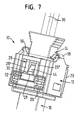
- the snap connection 18 comprises at least one film hinge, preferably at least one film hinge in combination with a kinematic Over-center beam system. In the present case it is on two opposite sides each have such a film hinge or such a combination is provided (compare, for example, also Fig. 5 to 7).
- the first connector part 14 can be plugged together State, for example, directly with the second connector part 16 be locked. Basically, however, a respective latching is also conceivable with the receiving part 12.
- the receiving part 12 is with a release button 20 provided.
- This release button 20, in particular a slide-like design is in the present embodiment with respect to the housing of the Receiving part 12 displaceable transversely to the insertion direction S.
- the release button 20 can, for example have at least one inclined surface 22 (compare, for example 11 to 16), the one with the connector part 12th associated counter surface 24 cooperates accordingly.
- the present Embodiment is on two opposite Sides each cooperating with a respective counter surface 24 Inclined surface 22 is provided.
- this has first connector part 14 for locking, for example with the second Connector part 16 has a resilient locking arm 26 which, for example, with a here the locking surface 28 associated with the second connector part 16 is feasible.
- the locking surface 28 is in the present case on a locking lug 30 of the second connector part 16 is provided.
- one such counter-latching element however, also on the receiving part 12, for example be provided.
- the resilient locking arm 26 made in two parts and with one the free ends of the two arms 26 ', 26 "connecting web 32 which the counter locking surface 28 to Establishes the locking connection behind (compare, for example, Fig. 7).
- the Pressing the release button 20 first released the latching connection 26, 30 and then the connector part 14 is pushed out of the receiving part 12.
- the snap connection 18 With its locking position taking connector part 14 or when closed Connector 10, the snap connection 18 in one are de-energized. Such a tension-free state the snap connection 18 can also be made in the receiving part 12 pulled out and taking its starting position accordingly Connector part 14 may be given.
- the release button comes when the connector part is inserted pushed back into its starting position in the receiving part.
- the release button is spring loaded into the starting position.
- the resilient connection is for releasing the latching connection 26, 30 Locking arm 26 can be deflected accordingly (compare, for example, FIG. 12).
- first connector part 14 e.g. a receptacle housing, in particular flat receptacle housing
- latchable electrical contacts 34 here e.g. Receptacles are each connected to a line 36.
- line 36 In the present case, for example two electrical contacts 34 and correspondingly two lines 36 are provided.
- the second connector part 16 can accordingly, for example, a connector housing, in particular include flat connector housings.
- the in this second connector part 16 insertable and lockable in this electrical Contacts 38, here e.g. Flat plugs, each with a cable 40 connected.
- the first connector part 14 with associated receiving part 12 for example a two-pin receptacle housing and the second connector part 16 for example a two-pin connector housing.
- the two are Connector parts 14, 16 each with a second lock 42, 43 for the electrical contacts 34 and 38 provided.
- the first connector part 14 is already like this inserted far into the receiving part 12 that the dead center of the snap connection 18 is reached.
- the resilient locking arm 26 was through a run-on slope provided on the catch 30 and acting on the web 32 44 pivoted outwards.
- this first connector part 14 by the Snap connection 18 immanent, previously applied during assembly Spring force drawn into the receiving part 12.
- this first connector part 14 is completely in the receiving part 12 retracted and locked for example with the second connector part 16.
- the free end of the resilient locking arm 26 which has the web 32 is snapped back into its starting position here, so that the web 32nd from the latching surface 38 of the second connector part 16, for example assigned detent 30 is engaged.
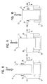
- Fig. 8 shows the simplified again 5 immediately before the connector is closed 10, that is, immediately before inserting the first connector part 14 in the receiving part 12.
- this phase is the first connector part 14 by the snap connection 18 in its shown in FIG. 8 Starting position charged.
- Fig. 9 shows again in a simplified schematic representation 6, in which the first connector part 14 in particular manually in the direction of the arrow F or in the insertion direction S so far is pressed into the receiving part 12 that the dead center of the snap connection 18 is reached. The first connector part 14 can then that is, due to the previously established snap connection 18 Spring force are automatically drawn into the receiving part 12.
- FIG. 10 again shows the in a simplified schematic representation 7, in which the connector part 14 completely in the Receiving part 14 is retracted.
- the connector part 14 in this phase for example with the second connector part 16 (see Fig. 7) be locked.
- the connector part 14 in this case is the connector part 14 in this case by that of the snap connection 18 immanent spring force loaded into the retracted position.
- Fig. 11 shows the phase immediately before the connector is opened 10.
- the first connector part 14 still takes its retracted position one in which it is via the resilient locking arm 26 and the locking lug 30, for example is locked with the second connector part 16.
- the release button 20 is then used to release the latching connection 26, 30 operated accordingly.
- this release button is 20 already so far depressed that by an appropriate application the web 32 of the elastic locking arm 26 to release the Latch 30 is pivoted outwards. You can do this by pressing the release button 20 inclined surfaces 46 engaging with the web 32, for example (Compare, for example, FIGS. 12 and 13) or the like his.
- the Detent connection 26, 30 released, but the connector part 14 takes over of the receiving part 12 still in its retracted position.
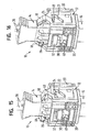
- Fig. 13 shows a further phase of the opening process, in which by a further actuation of the release button 20, the first connector part 14 from the Receiving part 12 is pushed. This happens through the interaction the inclined surfaces 22 of the release button 20 with the connector part 14 assigned counter surfaces 24, for example in the present case corresponding angled arms or lugs 48 of the connector part 14 are provided.
- the connector part 14 is now by pressing the release button again 20 initially pushed outward until the one shown in FIG. 14 Phase is reached in which the dead center of the snap connection 18 is exceeded. Should the release button 20 before reaching this dead center would be released again, the connector part 14 would again be drawn into the receiving part 14.
- Fig. 15 shows a further phase of the opening process, in which the dead center the snap connection 18 has already been exceeded and that Corresponding connector part 14 by the snap connection 18 immanent spring force is automatically pulled out of the receiving part 12.
- the connector part comes here 14 assigned counter surfaces 24 of the inclined surfaces 22 of the Release button 20 free.
- the release button 20 is resilient in its initial position loaded, it will automatically return to its starting position reset.
- Fig. 16 shows the final phase of the opening process in which the first connector part 14 assumes its outer starting position, in which it by which the snap connection 18 is loaded with spring force.
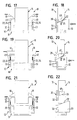
- 17 and 18 show a simplified schematic representation 11 again immediately before opening the connector 10, in which the connector part 14 is still completely in the receiving part 12 retracted and for example with a second connector part is locked. As already mentioned, the connector part 14 can for example also be locked with the receiving part 12.
- 19 and 20 show a simplified schematic representation 14 again, in which the first connector part 14 by pressing the release button 20 so far from the Receiving part 12 is pushed that the dead center of the snap connection 18 has already been reached. Subsequently, the connector part 14 by the spring force inherent in the snap connection 18 pushed outwards into the end position.
- 21 and 22 show a simplified schematic illustration 16, in which the first connector part 14 due to the spring force inherent in the snap connection 18 returns to its outward starting position, into which it is positioned by the Snap connection 18 is loaded.
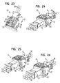
- FIG. 23 shows a schematic, perspective representation of an electrical one Connector 10 with a receiving part provided as a header 16 insertable connector part 14.
- the Locking for example between the connector part 14 and the Recording part or header 16 take place.
- this embodiment at least essentially the same structure as that have previously described embodiment.
- the connector parts 14, 16 are each bipolar, which have in the embodiments 24 to 26 provided connector parts 14, 16 each more as two poles. So are the two connector parts 14, 16 of the in FIG. 4th shown connector 10 each three-pole, the three contacts or lines 36, 40 each lie in one plane.
- the receiving part 12 serves here as well as in the embodiment according to FIG. 1 again as an inline connector, in the opposite sides the two connector parts 14, 16 can be inserted.
- the two connector parts 14, 16 each have, for example, four poles, the contacts or lines 36, 40 are arranged in two planes.
- the receiving part also serves here 12 again as an inline connector.
- two connector parts 14, 16 are provided, of two opposite one another Sides into one again serving as an inline connector Receiving part 12 can be inserted.
- the two connector parts 14, 16 are in this case, for example, six poles. Are in this too Fall the contacts or lines 36, 40 again in two planes arranged.
- FIGS. 24 to 26 can at least essentially the same structure as the embodiments described in connection with FIGS. 1 to 22 have.
Landscapes
- Details Of Connecting Devices For Male And Female Coupling (AREA)
Abstract
Description
- Fig. 1
- eine schematische, perspektivische Darstellung eines elektrischen Steckverbinders mit zwei beispielsweise zweipoligen Verbinderteilen, die von einander gegenüberliegenden Seiten her in ein als Inline-Verbinder dienendes Aufnahmeteil einsteckbar sind,
- Fig. 2
- eine mit der Fig. 1 vergleichbare Darstellung, wobei der elektrische Steckverbinder jedoch um 180° um seine Längsachse gedreht ist,
- Fig. 3
- eine mit der Fig. 1 vergleichbare Darstellung des elektrischen Steckverbinders, wobei das zweite Verbinderteil jedoch von dem Aufnahmeteil mit zugeordnetem ersten Verbinderteil getrennt ist,
- Fig. 4
- eine schematische, auseinander gezogene Darstellung des elektrischen Steckverbinders gemäß Fig. 1,
- Fig. 5
- eine schematische Darstellung des auf das zweite Verbinderteil aufgesteckten Aufnahmeteils mit zugeordnetem ersten Verbinderteil, wobei das erste Verbinderteil seine äußere Ausgangsposition einnimmt, in der es sich zumindest teilweise außerhalb des Aufnahmeteils befindet,
- Fig. 6
- eine schematische Darstellung des Aufnahmeteils mit zugeordnetem ersten Verbinderteil, wobei das erste Verbinderteil bereits so weit in das Aufnahmeteil eingesteckt ist, dass der Totpunkt der Schnappverbindung erreicht ist,
- Fig. 7
- eine schematische Darstellung des Aufnahmeteils mit zugeordnetem ersten Verbinderteil, wobei das erste Verbinderteil vollständig in das Aufnahmeteil eingezogen und verrastet ist,
- Fig. 8
- eine vereinfachte schematische Darstellung des mit dem Zustand gemäß Fig. 5 vergleichbaren Ausgangszustandes unmittelbar vor dem Schließen des Steckverbinders,
- Fig. 9
- eine vereinfachte schematische Darstellung des mit dem Zustand gemäß Fig. 6 vergleichbaren Zwischenzustandes des Schließvorgangs,
- Fig. 10
- eine vereinfachte schematische Darstellung des mit dem Zustand gemäß Fig. 7 vergleichbaren Endzustandes des Schließvorgangs,
- Fig. 11
- eine schematische Darstellung des Aufnahmeteils mit zugeordnetem ersten Verbinderteil unmittelbar vor dem Öffnen des Steckverbinders, wobei das erste Verbinderteil noch vollständig in das Aufnahmeteil eingezogen und verrastet ist,
- Fig. 12
- eine schematische Darstellung des Aufnahmeteils mit zugeordnetem ersten Verbinderteil in einer weiteren Phase des Öffnungsvorgangs, in der durch eine entsprechende Betätigung der Lösetaste die Rastverbindung gelöst wird,
- Fig. 13
- eine schematische Darstellung des Aufnahmeteils mit zugeordnetem ersten Verbinderteil in einer weiteren Phase des Öffnungsvorgangs, in der durch eine weitere Betätigung der Lösetaste das erste Verbinderteil durch die Lösetaste aus dem Aufnahmeteil gedrängt wird,
- Fig. 14
- eine schematische Darstellung des Aufnahmeteils mit zugeordnetem ersten Verbinderteil in einer weiteren Phase des Öffnungsvorgangs, in der das erste Verbinderteil durch eine weitere Betätigung der Lösetaste bereits so weit aus dem Aufnahmeteil gedrängt ist, dass der Totpunkt der Schnappverbindung bereits erreicht ist,
- Fig. 15
- eine schematische Darstellung des Aufnahmeteils mit zugeordnetem ersten Verbinderteil in einer weiteren Phase des Öffnungsvorgangs, in der das erste Verbinderteil durch die der Schnappverbindung immanente Federkraft aus dem Aufnahmeteil gezogen wird,
- Fig. 16
- eine schematische Darstellung des Aufnahmeteils mit zugeordnetem ersten Verbinderteil in der Endphase des Öffnungsvorgangs, in der das erste Verbinderteil wieder seine äußere Ausgangsposition einnimmt,
- Fig. 17
- einen vereinfachte schematische Darstellung des mit der Phase gemäß Fig. 11 vergleichbaren Ausgangszustandes unmittelbar vor dem Öffnen des Steckverbinders, wobei der Steckverbinder in einer Draufsicht wiedergegeben ist,
- Fig. 18
- eine schematische Seitenansicht des in der Fig. 17 gezeigten Steckverbinders,
- Fig. 19
- eine vereinfachte schematische Darstellung einer mit der Phase gemäß Fig. 14 vergleichbaren weiteren Phase des Öffnungsvorgangs, in der das erste Verbinderteil durch eine weitere Betätigung der Lösetaste bereits so weit aus dem Aufnahmeteil gedrängt ist, dass der Todpunkt der Schnappverbindung bereits erreicht ist, wobei der Steckverbinder in einer Draufsicht wiedergegeben ist,
- Fig. 20
- eine schematische Seitenansicht des in der Fig. 19 gezeigten Steckverbinders,
- Fig. 21
- eine vereinfachte schematische Darstellung der mit der Phase gemäß Fig. 16 vergleichbaren Endphase des Öffnungsvorgangs, in der das erste Verbinderteil bedingt durch die der Schnappverbindung immanente Federkraft wieder seine äußere Ausgangsposition einnimmt, wobei der Steckverbinder in einer Draufsicht wiedergegeben ist,
- Fig. 22
- eine schematische Seitenansicht des in der Fig. 21 gezeigten Steckverbinders,
- Fig. 23
- eine schematische, perspektivische Darstellung eines elektrischen Steckverbinders mit einem in ein als Header vorgesehenes Aufnahmeteil einsteckbaren Verbinderteil,
- Fig. 24
- eine schematische Darstellung einer mit der Ausführung gemäß Fig. 1 vergleichbaren weiteren Ausführungsform mit zwei dreipoligen Verbinderteilen,
- Fig. 25
- eine schematische Darstellung einer mit der Ausführung gemäß Fig. 1 vergleichbaren weiteren Ausführungsform mit zwei vierpoligen Verbinderteilen und
- Fig. 26
- eine schematische Darstellung einer mit der Ausführung gemäß Fig. 1 vergleichbaren weiteren Ausführungsform mit zwei sechspoligen Verbinderteilen.
- 10
- elektrischer Steckverbinder
- 12
- Aufnahmeteil
- 14
- erstes Verbinderteil
- 16
- zweites Verbinderteil
- 18
- Schnappverbindung
- 20
- Lösetaste
- 22
- Schrägfläche
- 24
- Gegenfläche
- 26
- federnder Rastarm
- 26'
- Teilarm
- 26"
- Teilarm
- 28
- Rastfläche
- 30
- Rastnase
- 32
- Steg
- 34
- elektrischer Kontakt, Steckhülse
- 36
- Leitung
- 38
- elektrischer Kontakt, Flachstecker
- 40
- Leitung
- 42
- Zweitverriegelung
- 43
- Zweitverriegelung
- 44
- Auflaufschräge
- 46
- Schrägfläche
- 48
- Arm, Ansatz
- S
- Steckrichtung
Claims (26)
- Elektrischer Steckverbinder (10) mit einem in ein Aufnahmeteil (12) einsteckbaren Verbinderteil (14), das in seiner eingesteckten Position verrastbar ist,
dadurch gekennzeichnet, dass das Verbinderteil (14) und das Aufnahmeteil (12) über eine Schnappverbindung (18) miteinander gekoppelt sind, die beim Zusammenstecken von Aufnahmeteil (12) und Verbinderteil (14) nach Überschreiten eines Totpunktes durch die ihr immanente Federkraft das Verbinderteil (14) in das Aufnahmeteil (12) zieht. - Steckverbinder nach Anspruch 1,
dadurch gekennzeichnet, dass die Schnappverbindung (18) beim Herausbewegen des Verbinderteils (14) aus dem Aufnahmeteil (12) nach Überschreiten des Totpunktes durch die ihr immanente Federkraft das Verbinderteil (14) aus dem Aufnahmeteil (12) zieht. - Steckverbinder nach Anspruch 1 oder 2,
dadurch gekennzeichnet, dass die Schnappverbindung (18) zumindest ein Filmscharnier umfasst. - Steckverbinder nach Anspruch 3,
dadurch gekennzeichnet, dass die Schnappverbindung (18) zumindest ein Filmscharnier in Kombination mit einem kinematischen Übertotpunkt-Balkensystem umfasst. - Steckverbinder nach einem der vorhergehenden Ansprüche, dadurch gekennzeichnet, dass das Aufnahmeteil (12) zum Lösen der Rastverbindung (26, 30) mit einer Lösetaste (20) versehen ist.
- Steckverbinder nach Anspruch 5,
dadurch gekennzeichnet, dass die Lösetaste (20) schieberartig ausgeführt ist. - Steckverbinder nach Anspruch 5 oder 6,
dadurch gekennzeichnet, dass die Lösetaste (20) bezüglich des Gehäuses des Aufnahmeteils (12) quer zur Steckrichtung (S) verschiebbar ist. - Steckverbinder nach einem der vorhergehenden Ansprüche,
dadurch gekennzeichnet, dass mit der Betätigung der Lösetaste (20) gleichzeitig das Verbinderteil (14) aus dem Aufnahmeteil (12) gedrängt wird. - Steckverbinder nach Anspruch 8,
dadurch gekennzeichnet, dass die Lösetaste (20) wenigstens eine Schrägfläche (22) aufweist, die mit einer dem Verbinderteil (12) zugeordneten Gegenfläche (24) so zusammenwirkt, dass mit der Betätigung der Lösetaste (20) das Verbinderteil (14) aus dem Aufnahmeteil (12) gedrängt wird. - Steckverbinder nach einem der vorhergehenden Ansprüche,
dadurch gekennzeichnet, dass mit der Betätigung der Lösetaste (20) zunächst die Rastverbindung (26, 30) gelöst und anschließend das Verbinderteil (14) aus dem Aufnahmeteil (12) gedrängt wird. - Steckverbinder nach einem der vorhergehenden Ansprüche,
dadurch gekennzeichnet, dass sich die Schnappverbindung (18) bei seine Rastposition einnehmendem Verbinderteil (14) in einem spannungsfreien Zustand befindet. - Steckverbinder nach einem der vorhergehenden Ansprüche,
dadurch gekennzeichnet, dass sich die Schnappverbindung (18) bei aus dem Aufnahmeteil (12) herausgezogenem und entsprechend seine Ausgangsposition einnehmendem Verbinderteil (14) in einem spannungsfreien Zustand befindet. - Steckverbinder nach einem der vorhergehenden Ansprüche,
dadurch gekennzeichnet, dass die Lösetaste (20) mit dem Einstecken des Verbinderteils (14) wieder in ihre Ausgangsposition drängbar oder federnd in die Ausgangsposition belastet ist. - Steckverbinder nach einem der vorhergehenden Ansprüche,
dadurch gekennzeichnet, dass das Aufnahmeteil (12) als Header vorgesehen ist. - Steckverbinder nach einem der Ansprüche 1 bis 13,
dadurch gekennzeichnet, dass das Aufnahmeteil (12) als Inline-Verbinder vorgesehen ist, in den von der gegenüberliegenden Seite her ein zweites Verbinderteil (16) einsteckbar ist. - Steckverbinder nach einem der vorhergehenden Ansprüche,
dadurch gekennzeichnet, dass das erste Verbinderteil (14) mit dem Aufnahmeteil (12) verrastbar ist. - Steckverbinder nach einem der vorhergehenden Ansprüche,
dadurch gekennzeichnet, dass das erste Verbinderteil (14) mit einem zweiten Verbinderteil (16) verrastbar ist. - Steckverbinder nach einem der vorhergehenden Ansprüche,
dadurch gekennzeichnet, dass das erste Verbinderteil (14) zur Verrastung mit dem Aufnahmeteil (12) bzw. dem zweiten Verbinderteil (16) einen federnden Rastarm (26) besitzt, der mit einer dem Aufnahmeteil (12) bzw. dem zweiten Verbinderteil (16) zugeordneten Rastfläche (28) in Eingriff bringbar ist. - Steckverbinder nach Anspruch 18,
dadurch gekennzeichnet, dass die Rastfläche (28) an einer Rastnase (30) des Aufnahmeteils (12) bzw. des zweiten Verbinderteils (16) vorgesehen ist. - Steckverbinder nach Anspruch 18 oder 19,
dadurch gekennzeichnet, dass der federnde Rastarm (26) zweiteilig ausgeführt und mit einem die freien Enden der beiden Teilarme (26', 26") verbindenden Steg (32) versehen ist, den die Gegenrastfläche (28) zur Herstellung der Rastverbindung (26, 30) hintergreift. - Steckverbinder nach einem der vorhergehenden Ansprüche,
dadurch gekennzeichnet, dass zum Lösen der Rastverbindung (26, 30) der federnde Rastarm (26) entsprechend auslenkbar ist. - Steckverbinder nach einem der vorhergehenden Ansprüche,
dadurch gekennzeichnet, dass das mit dem Aufnahmeteil (12) gekoppelte erste Verbinderteil (14) ein Steckhülsengehäuse, insbesondere Flachsteckhülsengehäuse, umfasst. - Steckverbinder nach Anspruch 22,
dadurch gekennzeichnet, dass das mit dem Aufnahmeteil (12) gekoppelte erste Verbinderteil (14) ein mehrpoliges Steckhülsengehäuse umfasst. - Steckverbinder nach einem der vorhergehenden Ansprüche,
dadurch gekennzeichnet, dass das zweite Verbinderteil (16) ein Steckergehäuse, insbesondere Flachsteckergehäuse, umfasst. - Steckverbinder nach Anspruch 24,
dadurch gekennzeichnet, dass das zweite Verbinderteil (16) ein mehrpoliges Steckergehäuse umfasst. - Steckverbinder nach einem der vorhergehenden Ansprüche,
dadurch gekennzeichnet, dass zumindest ein Verbinderteil (14, 16) mit einer Zweitverriegelung (42, 43) für die betreffenden elektrischen Kontakte (34, 38) versehen ist.
Priority Applications (2)
| Application Number | Priority Date | Filing Date | Title |
|---|---|---|---|
| DE50301224T DE50301224D1 (de) | 2003-04-04 | 2003-04-04 | Elektrischer Steckverbinder |
| EP20030007823 EP1465297B1 (de) | 2003-04-04 | 2003-04-04 | Elektrischer Steckverbinder |
Applications Claiming Priority (1)
| Application Number | Priority Date | Filing Date | Title |
|---|---|---|---|
| EP20030007823 EP1465297B1 (de) | 2003-04-04 | 2003-04-04 | Elektrischer Steckverbinder |
Publications (2)
| Publication Number | Publication Date |
|---|---|
| EP1465297A1 true EP1465297A1 (de) | 2004-10-06 |
| EP1465297B1 EP1465297B1 (de) | 2005-09-21 |
Family
ID=32842779
Family Applications (1)
| Application Number | Title | Priority Date | Filing Date |
|---|---|---|---|
| EP20030007823 Expired - Lifetime EP1465297B1 (de) | 2003-04-04 | 2003-04-04 | Elektrischer Steckverbinder |
Country Status (2)
| Country | Link |
|---|---|
| EP (1) | EP1465297B1 (de) |
| DE (1) | DE50301224D1 (de) |
Citations (3)
| Publication number | Priority date | Publication date | Assignee | Title |
|---|---|---|---|---|
| DE1152460B (de) * | 1961-11-15 | 1963-08-08 | Geyer Fa Christian | Steckvorrichtung |
| DE19828968A1 (de) * | 1998-06-29 | 1999-12-30 | Delphi Automotive Systems Gmbh | Elektrischer Steckverbinder |
| DE19828636A1 (de) * | 1998-06-26 | 2000-01-05 | Framatome Connectors Int | Steckverbinder mit Schnappverschluß |
-
2003
- 2003-04-04 EP EP20030007823 patent/EP1465297B1/de not_active Expired - Lifetime
- 2003-04-04 DE DE50301224T patent/DE50301224D1/de not_active Expired - Fee Related
Patent Citations (3)
| Publication number | Priority date | Publication date | Assignee | Title |
|---|---|---|---|---|
| DE1152460B (de) * | 1961-11-15 | 1963-08-08 | Geyer Fa Christian | Steckvorrichtung |
| DE19828636A1 (de) * | 1998-06-26 | 2000-01-05 | Framatome Connectors Int | Steckverbinder mit Schnappverschluß |
| DE19828968A1 (de) * | 1998-06-29 | 1999-12-30 | Delphi Automotive Systems Gmbh | Elektrischer Steckverbinder |
Also Published As
| Publication number | Publication date |
|---|---|
| DE50301224D1 (de) | 2005-10-27 |
| EP1465297B1 (de) | 2005-09-21 |
Similar Documents
| Publication | Publication Date | Title |
|---|---|---|
| DE60027611T2 (de) | Kabelverbinder mit gesteuerter Impedanz | |
| DE102004038123B4 (de) | Elektrischer Stecker und elektrische Steckeraufnahme | |
| DE69525623T2 (de) | Elektrischer Verbinder mit verbessertem Verriegelungssystem | |
| EP1972037B1 (de) | Elektrische steckerbuchse | |
| EP2839544B1 (de) | Prüfklemmenblock | |
| DE10045498A1 (de) | Elektrische Reihenklemme | |
| EP2442403A1 (de) | Schraubenlose Anschlussklemme | |
| EP3895256B1 (de) | Rundsteckverbinder mit verriegelung | |
| DE69619467T2 (de) | Elektrischer Verbinder mit Kontaktlagesicherungsvorrichtung welche das vollständige Einsetzen der Kontakte erleichtert | |
| EP3375046A1 (de) | Elektrische anschlussklemme | |
| WO2019192911A1 (de) | Elektrischer steckverbinder, modulares system und verfahren zur bereitstellung eines steckverbinders | |
| EP3375048A1 (de) | Steckkontakt | |
| EP3782235B1 (de) | Direktsteckverbinder | |
| DE4016114C2 (de) | Elektrischer Mehrkontakt-Verbinder, der eine geringe Verbindungs- und Trennkraft erfordert | |
| WO2008110190A2 (de) | Elektrischer verbinder mit einer staubabdeckung | |
| DE3643087A1 (de) | Schnellkupplungsklemme fuer den klemmenpol eines elektrischen geraetes | |
| CH652865A5 (de) | Steckverbinder. | |
| EP0757409B1 (de) | Steckverbinder | |
| DE102023128664B3 (de) | Ladesteckerhalter für eine Ladevorrichtung zum Laden von Elektrofahrzeugen, und Ladevorrichtung | |
| DE19532623B4 (de) | Elektrischer Stecker mit einem Betätigungsschieber | |
| EP3830905A1 (de) | Prüfsteckerblock und prüfklemmenblock | |
| EP1465297B1 (de) | Elektrischer Steckverbinder | |
| DE19929672B4 (de) | Verbinderanordnung für Koaxialleitungen | |
| DE102022134013A1 (de) | Steckverbinderteil mit entriegelbarem Steckelement | |
| DE19949386A1 (de) | Geräte-Anschlusskasten mit Schneidtechnik |
Legal Events
| Date | Code | Title | Description |
|---|---|---|---|
| GRAP | Despatch of communication of intention to grant a patent |
Free format text: ORIGINAL CODE: EPIDOSNIGR1 |
|
| PUAI | Public reference made under article 153(3) epc to a published international application that has entered the european phase |
Free format text: ORIGINAL CODE: 0009012 |
|
| 17P | Request for examination filed |
Effective date: 20040408 |
|
| AK | Designated contracting states |
Kind code of ref document: A1 Designated state(s): AT BE BG CH CY CZ DE DK EE ES FI FR GB GR HU IE IT LI LU MC NL PT SE SI SK TR |
|
| AX | Request for extension of the european patent |
Extension state: AL LT LV MK RO |
|
| GRAS | Grant fee paid |
Free format text: ORIGINAL CODE: EPIDOSNIGR3 |
|
| AKX | Designation fees paid |
Designated state(s): DE FR IT |
|
| GRAA | (expected) grant |
Free format text: ORIGINAL CODE: 0009210 |
|
| RBV | Designated contracting states (corrected) |
Designated state(s): DE FR IT |
|
| AK | Designated contracting states |
Kind code of ref document: B1 Designated state(s): DE FR IT |
|
| REF | Corresponds to: |
Ref document number: 50301224 Country of ref document: DE Date of ref document: 20051027 Kind code of ref document: P |
|
| ET | Fr: translation filed | ||
| PLBE | No opposition filed within time limit |
Free format text: ORIGINAL CODE: 0009261 |
|
| STAA | Information on the status of an ep patent application or granted ep patent |
Free format text: STATUS: NO OPPOSITION FILED WITHIN TIME LIMIT |
|
| 26N | No opposition filed |
Effective date: 20060622 |
|
| PGFP | Annual fee paid to national office [announced via postgrant information from national office to epo] |
Ref country code: DE Payment date: 20070329 Year of fee payment: 5 |
|
| PGFP | Annual fee paid to national office [announced via postgrant information from national office to epo] |
Ref country code: IT Payment date: 20070511 Year of fee payment: 5 |
|
| PGFP | Annual fee paid to national office [announced via postgrant information from national office to epo] |
Ref country code: FR Payment date: 20070411 Year of fee payment: 5 |
|
| PG25 | Lapsed in a contracting state [announced via postgrant information from national office to epo] |
Ref country code: DE Free format text: LAPSE BECAUSE OF NON-PAYMENT OF DUE FEES Effective date: 20081101 |
|
| REG | Reference to a national code |
Ref country code: FR Ref legal event code: ST Effective date: 20081231 |
|
| PG25 | Lapsed in a contracting state [announced via postgrant information from national office to epo] |
Ref country code: FR Free format text: LAPSE BECAUSE OF NON-PAYMENT OF DUE FEES Effective date: 20080430 |
|
| PG25 | Lapsed in a contracting state [announced via postgrant information from national office to epo] |
Ref country code: IT Free format text: LAPSE BECAUSE OF NON-PAYMENT OF DUE FEES Effective date: 20080404 |