EP1464793A1 - Nockenwellenauslegung für Motoren - Google Patents
Nockenwellenauslegung für Motoren Download PDFInfo
- Publication number
- EP1464793A1 EP1464793A1 EP03290829A EP03290829A EP1464793A1 EP 1464793 A1 EP1464793 A1 EP 1464793A1 EP 03290829 A EP03290829 A EP 03290829A EP 03290829 A EP03290829 A EP 03290829A EP 1464793 A1 EP1464793 A1 EP 1464793A1
- Authority
- EP
- European Patent Office
- Prior art keywords
- camshaft
- support shaft
- rivet
- shaft
- target
- Prior art date
- Legal status (The legal status is an assumption and is not a legal conclusion. Google has not performed a legal analysis and makes no representation as to the accuracy of the status listed.)
- Granted
Links
Images


Classifications
-
- F—MECHANICAL ENGINEERING; LIGHTING; HEATING; WEAPONS; BLASTING
- F01—MACHINES OR ENGINES IN GENERAL; ENGINE PLANTS IN GENERAL; STEAM ENGINES
- F01L—CYCLICALLY OPERATING VALVES FOR MACHINES OR ENGINES
- F01L1/00—Valve-gear or valve arrangements, e.g. lift-valve gear
- F01L1/02—Valve drive
- F01L1/04—Valve drive by means of cams, camshafts, cam discs, eccentrics or the like
- F01L1/047—Camshafts
- F01L1/053—Camshafts overhead type
-
- Y—GENERAL TAGGING OF NEW TECHNOLOGICAL DEVELOPMENTS; GENERAL TAGGING OF CROSS-SECTIONAL TECHNOLOGIES SPANNING OVER SEVERAL SECTIONS OF THE IPC; TECHNICAL SUBJECTS COVERED BY FORMER USPC CROSS-REFERENCE ART COLLECTIONS [XRACs] AND DIGESTS
- Y10—TECHNICAL SUBJECTS COVERED BY FORMER USPC
- Y10T—TECHNICAL SUBJECTS COVERED BY FORMER US CLASSIFICATION
- Y10T29/00—Metal working
- Y10T29/49—Method of mechanical manufacture
- Y10T29/49229—Prime mover or fluid pump making
- Y10T29/49293—Camshaft making
-
- Y—GENERAL TAGGING OF NEW TECHNOLOGICAL DEVELOPMENTS; GENERAL TAGGING OF CROSS-SECTIONAL TECHNOLOGIES SPANNING OVER SEVERAL SECTIONS OF THE IPC; TECHNICAL SUBJECTS COVERED BY FORMER USPC CROSS-REFERENCE ART COLLECTIONS [XRACs] AND DIGESTS
- Y10—TECHNICAL SUBJECTS COVERED BY FORMER USPC
- Y10T—TECHNICAL SUBJECTS COVERED BY FORMER US CLASSIFICATION
- Y10T403/00—Joints and connections
- Y10T403/49—Member deformed in situ
- Y10T403/4924—Inner member is expanded by longitudinally inserted element
-
- Y—GENERAL TAGGING OF NEW TECHNOLOGICAL DEVELOPMENTS; GENERAL TAGGING OF CROSS-SECTIONAL TECHNOLOGIES SPANNING OVER SEVERAL SECTIONS OF THE IPC; TECHNICAL SUBJECTS COVERED BY FORMER USPC CROSS-REFERENCE ART COLLECTIONS [XRACs] AND DIGESTS
- Y10—TECHNICAL SUBJECTS COVERED BY FORMER USPC
- Y10T—TECHNICAL SUBJECTS COVERED BY FORMER US CLASSIFICATION
- Y10T74/00—Machine element or mechanism
- Y10T74/21—Elements
- Y10T74/2101—Cams
Definitions
- the present invention relates to camshaft arrangements for engines and in particular to a camshaft including a camshaft element mounted thereon for co-rotation therewith.
- a camshaft element may comprise, for example but not exclusively, a target member for a camshaft rotational speed and position sensing arrangement.
- camshafts with targets for rotational speed and position sensors and a prior art example can be found in GB-2317958.
- the camshaft sensor target is formed in one piece with the camshaft itself. This requires machining operations to be carried out on the camshaft so as to produce the target lobes from solid.
- a camshaft sensor target is formed as a separate component and is then attached to the camshaft for co-rotation. Examples of such arrangements may be found in US-5627464, US-5987973 and in US-6277045. In each of these cases, a separate component incorporating a camshaft sensor target is attached to an end of the camshaft using a threaded fastener.
- the width of the sensor-to-target air-gap is often dependent on a tolerance stack that comprises essentially two components.
- the first part is the tolerance stack built up in making the sensor itself and putting it into position, often on a bracket or boss on the cylinder head or cam-cover.
- the second component is the tolerance stack in making the target, fitting it to the camshaft and in putting the camshaft into place with due consideration to running clearances and wear in service.
- camshaft lobes and journal elements are made as components that are initially separate from a tube forming the basis of the camshaft. The lobes and journals are then pushed onto the tube and fixed in place by a permanent interlock.
- the preferred approach is to stake or crimp the lobes and journals in place, with alternatives of welding and brazing being suggested. While the suggested methods of interlocking may be acceptable for cam lobes and bearing journals, it should be born in mind that these are fairly sizeable parts.
- a target arrangement for camshaft rotational speed and position sensing is to be provided on a portion of a camshaft that is not solid, it may prove difficult to hold it in position with a sufficient level of accuracy. This is particularly so if the target used is formed from a thin plate. For example, with a hollow portion of a camshaft, staking in place a pre-formed target by crimping it to the hollow portion may result in crush deformation of the target, the shaft or both. That in turn may cause variations in sensor-to-target air-gap tolerance that are unacceptable. Similar problems may arise from heat joints such as welding or brazing due to distortion on heating or cooling and shrinkage. In addition, such heat joints call for complicated production methods and equipment.
- camshaft elements such as sensor targets to camshafts and to do so with good build consistency in high volume applications. It is also apparent that this need may be particularly difficult to satisfy if such a camshaft element is to be applied to a portion of a camshaft that is hollow.
- the present invention provides a camshaft for an engine, said camshaft comprising a support shaft carrying in the region of one end thereof a camshaft shaft element for co-rotation therewith, characterised in that said shaft element is captured on said support shaft by the head of a rivet formed from plastic deformation of said end of said support shaft.
- Said support shaft may include a hollow portion extending inwardly from one end thereof.
- Said support shaft may comprise a tube.
- Said hollow portion may extend through at least part of the portion of said support shaft that is adapted to support said camshaft element.
- Said rivet may comprise a radially extending eyelet rivet.
- Said rivet head may be formed by means of a radial cold flow forming technique, such as an orbital or daisy riveting technique.
- Said rivet head may be formed from a deformation zone of said support shaft, which zone overhangs said camshaft element when in place and preferably includes, before deformation, a hollow rim at said end.
- Said camshaft shaft element may comprise a rotation sensor target member, preferably a substantially planar target member and preferably formed from a sheet or plate material. Said camshaft element may be located on a journal at the end of said support shaft and may be captured against a shoulder on said support shaft by said rivet head.
- the present invention also provides a method of producing a camshaft for an engine, the method including:
- the method may include riveting said shaft element onto said support shaft using a radial cold flow forming technique.
- the method may include riveting said shaft element onto said support shaft using an orbital or daisy riveting technique.
- the present invention also provides an engine including a camshaft according to the present invention or a camshaft made according to the method of the present invention.
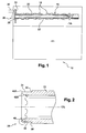
- an engine 10 includes a cylinder block 12 on which is mounted a cylinder head 14.
- An overhead camshaft assembly 16 runs in the cylinder head 14.
- the camshaft 16 is a tubular camshaft and is built up from a series of camshaft elements that include a series of camshaft lobes 18 and bearing journals 20, each of which is interlocked onto a tubular support shaft 22.
- the camshaft 16 carries a further camshaft element in the form of a rotation sensor target member 24 that is mounted onto one end 26 of the camshaft 16.
- the target member 24 is fixed onto the camshaft 16 by a rivet head 28 formed from plastic deformation of the support shaft 22 itself, the support shaft 22 acting as the shank of the rivet 22, 28 thus formed.
- the technique for formation of the rivet head 28 will be described in greater detail below.
- the rivet head 28 keeps the target member 24 in place on the support shaft 22, at least from the point of view of axial location and preferably also ensures co-rotation with that shaft 22 of the target member 24.
- the target member 24 is used in co-operation with a sensor 30 for the detection of the rotational speed and/or position of the camshaft 16.
- the information thus obtained may be processed to determine the phase of the camshaft 16 in relation to the rotation of an associated crankshaft (not illustrated) and the phase information may typically be used for timing fuel injection events or controlling variable valve timing.
- the sensor 30 may be axially reading as illustrated, i.e. end-on to a planar face 32 of the target member 24, or may be radially reading.
- Target form will depend on the type of sensor 30 used and the information sought and may for example comprise a hall effect sensor.
- the target member 24 may conveniently be formed from a substantially planar material such as a sheet or thin plate. A typical thickness may be a few millimetres.
- the target member planar face 32 extends radially outwards from a region of the target member 24 that sits on a target journal 34 of the support shaft 22.
- This region of the target member 24 may for convenience be referred to as the target hub 36 and, when in position on the support shaft 22, preferably extends all the way around the target journal 34.
- the target journal 34 and may be of reduced diameter in comparison with the rest of the tubular support shaft 22.
- the target member 24 is fitted onto the target journal 34, e.g. by sliding or pressing, and is preferably positioned close to or substantially abutting a shoulder 38.
- the length of the target journal 34 is fixed by the axial position of the shoulder 38 and this feature in turn fixes the nominal axial position on the camshaft assembly 16 of the target face 32.
- the outer edge of the shoulder 38 is preferably lightly chamfered or de-burred so as to reduce the likelihood of burrs or similar interfering with proper axial positioning of the target member 24 or of distorting it and resulting in axial run-out.
- the target member 24 on the support shaft 22 is a rivet head 28 formed by plastic deformation of an end 26 of the support shaft 22 itself that holds the target member 24 in position, at least axially and also for co-rotation.
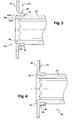
- the end region 26 of the tubular support shaft 22 is considered in some detail for a camshaft assembly 16 according to a first version of the present invention.
- the target hub 36 may comprise a tubular portion 40 that extends axially away from the target face 32 and may be formed by for example a pressing or stamping technique.
- the tubular portion 40 of the target hub 36 sits on the target journal 34 such that the free end of the tubular portion 38 butts up against the shoulder 38 that defines the inner end and therefore length of the target journal 34.
- the target hub 36 supports the target face 32, which is therefore spaced away from the shoulder 38. This ensures that the distance from the datum provided by the shoulder 38 to the target face 32 is substantially constant and is not affected by any curvature present in the translation of the target hub 36 from an axial to a radial direction.
- the target member 24 is confined to substantially one plane and may, for example, comprise a flat washer-type piece having targets in the form of holes or supported as radially extending teeth.
- production of the target member 24 may be simpler than in the first version but also appreciated that the length of the target journal 34 will preferably be correspondingly shorter.
- the end 26 of the support shaft 22 includes an external chamfer 42A adapted to ease initial introduction of the target member 24 onto the target journal 34.
- the inside of the support shaft may include an internal chamfer 42B.
- the length of the target member journal 34 is such that, once the target member 24 is in position, there is sufficient support shaft material overhanging the outer face of the target member as to permit formation of the rivet head 28 directly from the material of the support shaft 22 itself. This overhanging material may for convenience be referred to as a deformation zone 46, so as to indicate that it is this portion of the support shaft 22 that is used to form the rivet head 28.
- the riveting of the target member 24 onto the end of the camshaft assembly 16 may be broadly the same for each of the exemplary arrangements under consideration and will therefore be discussed in common between them.
- riveting is meant upsetting by plastic deformation a quantity of material so as to form a rivet head 28 that holds several assembled parts together.
- the rivet head 28 may for example be in the form of a bulge that extends radially away from the undisturbed diameter of the target journal 34.
- the rivet head 28 may be one of several shapes such as for example a substantially planar surface, a mushroom head or a countersunk rivet head.
- the specific shape of the rivet head 26 is preferably not a limiting factor, but rather the principle of forming the rivet head 28 out of the material of the support shaft 22 itself.
- the plastic deformation is applied by way of radial deformation of the end of the hollow support shaft 22, the deformation being applied outwardly so as to form such a rivet head that captures the target member 24 onto the target journal and prevents it from easily coming off the end 26 of the camshaft assembly 16.
- the rivet head 28 may then comprise a form of rivet known in the art as an eyelet rivet, e.g. indicating that the rivet head 26 is formed integrally with, and preferably from, a tubular or at least partially hollow member.
- the purpose of the rivet head 28 is to capture the target member 24 on the camshaft assembly 16 against dismounting and preferably in such a manner that the target face 32 and any associated targets are fixed within predetermined tolerances for axial positioning and axial run-out.
- the tolerances themselves will be determined by the specific sensor installation employed.
- Such a sensor target member 24 is anticipated to be, in preference for a tubular camshaft 16, a lightweight part and an axial force applied by the rivet head 28 should be sufficient to hold the target member 24 against the shoulder 38 and guarantee co-rotation. It will be appreciated, however, that further fixation may be employed as necessary to ensure co-rotation and/or angular alignment, e.g. radial keying or splines.
- camshaft elements other than a rotation sensor target member 24 may be captured onto a camshaft assembly by means of a rivet head 28 formed out of the end of the camshaft 16.
- a rivet head 28 could be used to hold on a camshaft lobe, bearing journal, thrust plate or drive wheel, at least against axial displacement if not also against rotational slippage for which other locking techniques may be needed in addition.
- the support shaft 22 is not necessarily tubular, or at least not hollow all the way through.
- the present invention may be applied in substantially the same way as for a hollow support shaft 22.
- that end of the shaft could still be plastically deformed so as to form a rivet head without necessarily departing from the spirit and scope of the present invention when considered in its broadest sense.
- the present invention is, however, considered particularly suited to implementation for hollow or tubular camshaft assemblies 16.
- a direct thrust or press riveting technique may be employed, but this is not preferred and in particular not preferred for tubular camshafts.
- the high thrust forces used may upset the rivet shank.
- such upsetting of the shank may translate into radial run-out of the camshaft 16 at some point along its length.
- metallurgical problems may be caused in the region of the rivet head 28 due to rapid metal deformation and the process can be noisy. For this reason, a radial cold flow riveting process is much preferred, as will now be considered in reference to Figures 7 and 8.
- FIG. 7 the general principle of a radial cold flow forming technique is illustrated in the form of a basic orbital or gyroscopic riveting motion.
- a tool member known in the art as a peen 48 is mounted in a machine head (not shown) at a predetermined angle.
- the rivet angle is set in dependence on the result desired, e.g. from 1° to 8°, and may be found by the skilled person during development testing.
- the peen 48 is angled towards the axis of rotation and its riveting anvil 50 sits inside for tubular or hollow rivet work-pieces 22 or on top for solid work-pieces.
- the spindle of the machine head rotates the off-set end 52 of the peen 48 around the centre-line of the machine head, which is preferably aligned with the centre-line C/L of the camshaft 16.
- This rotation may be unidirectional and is represented as such by the circle 54, a typical rotary speed being 1500 to 3000 revolutions per minute.
- the peen 48 is then brought into contact with the deformation zone 46 of a hollow support shaft 22 of a camshaft 16 according to the present invention and a preferably constant pressure is applied, the target member 24 having already been fitted.
- a variation on the theme of radial cold flow forming is considered in the form of so-called "daisy" riveting.
- the general principle is similar to the orbital or gyroscopic riveting discussed in relation to Figure 7, the main difference being that the rotation scribes a more complex shape.
- four passes / petals are shown per cycle, the passes all touching the centre and being angularly equi-spaced thereabouts. More passes or less are possible and the rivet set peen 48 may be considered to describe a petal for each revolution of the machine head spindle.
- the material may be pushed outwards as the peen 48 moves radially outwards and then inwards as the peen 48 moves back towards the centre.
- This version usually increases the riveting time when compared with orbital riveting but may prove preferable if working with a thicker tubular support shaft or a solid one.
- the use of a radial cold flow forming technique may well take longer per work-piece than simple press-riveting.
- the principle of operation means that the upsetting load applied to the support shaft 22 is up to six times lower than a press riveting technique to produce the same level of deformation of the deformation zone 46. The use of this significantly reduced upsetting load helps reduce the chances of distortion of the cam sensor target member 24 and of its support shaft 22.
- the improvements in target mounting and general camshaft production reduce the pressure on the sensor system with regard to tolerance stacking and help keep down camshaft production costs, as no welding or separate mechanical fixings are called for. There is little or no change in the structure of the parts being joined and only limited deformation and pressure need be put on them. As multiple head riveting machines can be used and the process is suitable for a high degree of automation, along with little noise pollution, the process is considered to be a significant improvement and addition to the art of camshaft production.
Landscapes
- Engineering & Computer Science (AREA)
- Mechanical Engineering (AREA)
- General Engineering & Computer Science (AREA)
- Valve-Gear Or Valve Arrangements (AREA)
Priority Applications (3)
| Application Number | Priority Date | Filing Date | Title |
|---|---|---|---|
| EP03290829A EP1464793B1 (de) | 2003-04-02 | 2003-04-02 | Nockenwellenauslegung für Motoren |
| DE60317875T DE60317875T2 (de) | 2003-04-02 | 2003-04-02 | Nockenwellenauslegung für Motoren |
| US10/815,844 US7314031B2 (en) | 2003-04-02 | 2004-04-02 | Camshaft arrangements for engines |
Applications Claiming Priority (1)
| Application Number | Priority Date | Filing Date | Title |
|---|---|---|---|
| EP03290829A EP1464793B1 (de) | 2003-04-02 | 2003-04-02 | Nockenwellenauslegung für Motoren |
Publications (2)
| Publication Number | Publication Date |
|---|---|
| EP1464793A1 true EP1464793A1 (de) | 2004-10-06 |
| EP1464793B1 EP1464793B1 (de) | 2007-12-05 |
Family
ID=32842870
Family Applications (1)
| Application Number | Title | Priority Date | Filing Date |
|---|---|---|---|
| EP03290829A Expired - Fee Related EP1464793B1 (de) | 2003-04-02 | 2003-04-02 | Nockenwellenauslegung für Motoren |
Country Status (3)
| Country | Link |
|---|---|
| US (1) | US7314031B2 (de) |
| EP (1) | EP1464793B1 (de) |
| DE (1) | DE60317875T2 (de) |
Cited By (3)
| Publication number | Priority date | Publication date | Assignee | Title |
|---|---|---|---|---|
| DE102006000846A1 (de) * | 2006-01-05 | 2007-07-19 | Mahle International Gmbh | Nockenwelle |
| WO2007131865A1 (de) * | 2006-05-13 | 2007-11-22 | Schaeffler Kg | Verfahren zur verbindung einer nockenwelle mit einem nockenwellenversteller |
| WO2012171595A1 (de) * | 2011-06-17 | 2012-12-20 | Daimler Ag | Verbindungsanordnung eines wellenteils mit einem nabenteil |
Families Citing this family (11)
| Publication number | Priority date | Publication date | Assignee | Title |
|---|---|---|---|---|
| US20070039173A1 (en) * | 2005-08-04 | 2007-02-22 | Braun Thomas A | Method and apparatus for staking a hardened shaft |
| JP5219246B2 (ja) * | 2007-12-28 | 2013-06-26 | 武蔵精密工業株式会社 | カムシャフトの成形方法 |
| DE102009001661A1 (de) * | 2009-03-19 | 2010-09-23 | Zf Friedrichshafen Ag | Anordnung zur Befestigung und axialen Fixierung einer Welle in einem Bauteil |
| DE102009022869A1 (de) * | 2009-05-27 | 2010-12-09 | Hydraulik-Ring Gmbh | Flügelzellennockenwellenverstellersystem |
| DE102009049218A1 (de) * | 2009-10-13 | 2011-04-28 | Mahle International Gmbh | Nockenwelle für eine Brennkraftmaschine |
| DE102009050779B4 (de) | 2009-10-27 | 2016-05-04 | Hilite Germany Gmbh | Schwenkmotornockenwellenversteller mit einer Reibscheibe und Montageverfahren |
| DE102009052841A1 (de) * | 2009-11-13 | 2011-05-19 | Hydraulik-Ring Gmbh | Nockenwelleneinsatz |
| DE102010045358A1 (de) | 2010-04-10 | 2011-10-13 | Hydraulik-Ring Gmbh | Schwenkmotornockenwellenversteller mit einem Hydraulikventil |
| DE102010019005B4 (de) | 2010-05-03 | 2017-03-23 | Hilite Germany Gmbh | Schwenkmotorversteller |
| CN102906462B (zh) * | 2010-05-18 | 2015-06-10 | 丰田自动车株式会社 | 内啮合齿轮的紧固构造 |
| CN107869366B (zh) | 2016-09-22 | 2022-03-22 | 博格华纳公司 | 滚压成型液压可变凸轮正时相位器 |
Citations (10)
| Publication number | Priority date | Publication date | Assignee | Title |
|---|---|---|---|---|
| US3800579A (en) * | 1971-02-24 | 1974-04-02 | Langendorf Watch Co | Wobble riveting machine |
| GB2263516A (en) * | 1992-01-27 | 1993-07-28 | Go Gro Ind Ltd | "connection of tubular members in holes" |
| US5469759A (en) * | 1992-07-13 | 1995-11-28 | The Torrington Company | Camshaft and method of making a camshaft |
| US5627464A (en) | 1995-03-17 | 1997-05-06 | Mitsubishi Denki Kabushiki Kaisha | Rotation angle detecting device for a camshaft provided in an internal combustion engine |
| GB2317958A (en) | 1996-10-03 | 1998-04-08 | Rover Group | A rotational speed and position sensing system |
| US5987973A (en) | 1996-07-24 | 1999-11-23 | Honda Giken Kogyo Kabushiki Kaisha | Rotation detecting device of an engine |
| US6182361B1 (en) * | 1999-05-20 | 2001-02-06 | The Torrington Company | Method for assembling a camshaft |
| US6277045B1 (en) | 1999-12-08 | 2001-08-21 | Daimlerchrysler Corporation | Thin profile cam sprocket with integrated timing target |
| US20020011222A1 (en) * | 2000-02-29 | 2002-01-31 | Bombardier-Rotax Gmbh | Modular engine family |
| DE10129419A1 (de) * | 2001-06-19 | 2003-01-02 | Opel Adam Ag | Gebaute Nockenwelle |
Family Cites Families (4)
| Publication number | Priority date | Publication date | Assignee | Title |
|---|---|---|---|---|
| US4512441A (en) * | 1980-02-25 | 1985-04-23 | General Screw Products Company | Blowdown fitting |
| JPS61266132A (ja) * | 1985-05-21 | 1986-11-25 | Musashi Seimitsu Ind Co Ltd | 組立カムシヤフトの製造方法 |
| US5101554A (en) * | 1986-10-01 | 1992-04-07 | Emitec Gesellschaft Fur Emissionstechnologie Mbh | Process for producing an assembled camshaft as well as assembled camshaft consisting of a shaft tube and slid-on elements |
| US5287615A (en) * | 1987-12-15 | 1994-02-22 | Emitech Gesellschaft Fur Emissionstechnologie Mbh | Process for joining a hollow shaft and elements slid thereon |
-
2003
- 2003-04-02 DE DE60317875T patent/DE60317875T2/de not_active Expired - Lifetime
- 2003-04-02 EP EP03290829A patent/EP1464793B1/de not_active Expired - Fee Related
-
2004
- 2004-04-02 US US10/815,844 patent/US7314031B2/en active Active
Patent Citations (10)
| Publication number | Priority date | Publication date | Assignee | Title |
|---|---|---|---|---|
| US3800579A (en) * | 1971-02-24 | 1974-04-02 | Langendorf Watch Co | Wobble riveting machine |
| GB2263516A (en) * | 1992-01-27 | 1993-07-28 | Go Gro Ind Ltd | "connection of tubular members in holes" |
| US5469759A (en) * | 1992-07-13 | 1995-11-28 | The Torrington Company | Camshaft and method of making a camshaft |
| US5627464A (en) | 1995-03-17 | 1997-05-06 | Mitsubishi Denki Kabushiki Kaisha | Rotation angle detecting device for a camshaft provided in an internal combustion engine |
| US5987973A (en) | 1996-07-24 | 1999-11-23 | Honda Giken Kogyo Kabushiki Kaisha | Rotation detecting device of an engine |
| GB2317958A (en) | 1996-10-03 | 1998-04-08 | Rover Group | A rotational speed and position sensing system |
| US6182361B1 (en) * | 1999-05-20 | 2001-02-06 | The Torrington Company | Method for assembling a camshaft |
| US6277045B1 (en) | 1999-12-08 | 2001-08-21 | Daimlerchrysler Corporation | Thin profile cam sprocket with integrated timing target |
| US20020011222A1 (en) * | 2000-02-29 | 2002-01-31 | Bombardier-Rotax Gmbh | Modular engine family |
| DE10129419A1 (de) * | 2001-06-19 | 2003-01-02 | Opel Adam Ag | Gebaute Nockenwelle |
Cited By (4)
| Publication number | Priority date | Publication date | Assignee | Title |
|---|---|---|---|---|
| DE102006000846A1 (de) * | 2006-01-05 | 2007-07-19 | Mahle International Gmbh | Nockenwelle |
| US7621245B2 (en) | 2006-01-05 | 2009-11-24 | Mahle International Gmbh | Camshaft |
| WO2007131865A1 (de) * | 2006-05-13 | 2007-11-22 | Schaeffler Kg | Verfahren zur verbindung einer nockenwelle mit einem nockenwellenversteller |
| WO2012171595A1 (de) * | 2011-06-17 | 2012-12-20 | Daimler Ag | Verbindungsanordnung eines wellenteils mit einem nabenteil |
Also Published As
| Publication number | Publication date |
|---|---|
| US20040255885A1 (en) | 2004-12-23 |
| EP1464793B1 (de) | 2007-12-05 |
| DE60317875T2 (de) | 2008-11-27 |
| DE60317875D1 (de) | 2008-01-17 |
| US7314031B2 (en) | 2008-01-01 |
Similar Documents
| Publication | Publication Date | Title |
|---|---|---|
| EP1464793B1 (de) | Nockenwellenauslegung für Motoren | |
| US4903543A (en) | Camshaft for controlling valves in internal combustion engines and method of manufacturing the camshaft | |
| US4774852A (en) | Campshaft for actuating valve tappets in internal combustion engines | |
| US5435207A (en) | Camshaft and method of making a camshaft | |
| US20030115755A1 (en) | Wheel bearing assembly for motor vehicles | |
| US20030024345A1 (en) | Crankshaft damper with integral pulse ring and method | |
| US5469759A (en) | Camshaft and method of making a camshaft | |
| US8210143B2 (en) | Adjustable camshaft arrangement | |
| JP3577635B2 (ja) | モータビークルのホイール用のハブ軸受けユニットを機械加工する方法 | |
| US20010026727A1 (en) | Caulking roller and sintered flanged pulley caulked by the caulking roller | |
| KR20160111525A (ko) | 차량 모듈을 조립하기 위한 방법 | |
| JPH04318209A (ja) | エンジンのバルブリフタの製造方法 | |
| US7252056B2 (en) | Target wheel pre-assembly for a camshaft phaser | |
| US6978750B2 (en) | Cam follower provided with rocker arm made of sheet metal | |
| JP2013194544A (ja) | センサープレート及び該センサープレートを備えたカムシャフト | |
| JP4123883B2 (ja) | ころ軸受の製造方法 | |
| JP6037017B2 (ja) | 組立カムシャフト | |
| JP2000202536A (ja) | 組立カムシャフトの製造方法 | |
| EP1447526A1 (de) | Nockenfolger mit blechkipphebel | |
| JP2719487B2 (ja) | カムシャフトの製造方法 | |
| Horvat et al. | Assembled camshafts for automotive engines | |
| JPH10317926A (ja) | 内燃機関用スプリングリテーナ及びその製造方法 | |
| US20230407769A1 (en) | Method for manufacturing a piston indicator for a camshaft | |
| JP2763375B2 (ja) | カムシャフトの製造方法 | |
| CN117469007A (zh) | 用于制造凸轮轴的方法 |
Legal Events
| Date | Code | Title | Description |
|---|---|---|---|
| PUAI | Public reference made under article 153(3) epc to a published international application that has entered the european phase |
Free format text: ORIGINAL CODE: 0009012 |
|
| AK | Designated contracting states |
Kind code of ref document: A1 Designated state(s): AT BE BG CH CY CZ DE DK EE ES FI FR GB GR HU IE IT LI LU MC NL PT RO SE SI SK TR |
|
| AX | Request for extension of the european patent |
Extension state: AL LT LV MK |
|
| 17P | Request for examination filed |
Effective date: 20050412 |
|
| AKX | Designation fees paid |
Designated state(s): BE DE FR GB |
|
| GRAP | Despatch of communication of intention to grant a patent |
Free format text: ORIGINAL CODE: EPIDOSNIGR1 |
|
| GRAS | Grant fee paid |
Free format text: ORIGINAL CODE: EPIDOSNIGR3 |
|
| GRAA | (expected) grant |
Free format text: ORIGINAL CODE: 0009210 |
|
| AK | Designated contracting states |
Kind code of ref document: B1 Designated state(s): BE DE FR GB |
|
| REG | Reference to a national code |
Ref country code: GB Ref legal event code: FG4D |
|
| REF | Corresponds to: |
Ref document number: 60317875 Country of ref document: DE Date of ref document: 20080117 Kind code of ref document: P |
|
| ET | Fr: translation filed | ||
| PG25 | Lapsed in a contracting state [announced via postgrant information from national office to epo] |
Ref country code: BE Free format text: LAPSE BECAUSE OF FAILURE TO SUBMIT A TRANSLATION OF THE DESCRIPTION OR TO PAY THE FEE WITHIN THE PRESCRIBED TIME-LIMIT Effective date: 20071205 |
|
| PLBE | No opposition filed within time limit |
Free format text: ORIGINAL CODE: 0009261 |
|
| STAA | Information on the status of an ep patent application or granted ep patent |
Free format text: STATUS: NO OPPOSITION FILED WITHIN TIME LIMIT |
|
| 26N | No opposition filed |
Effective date: 20080908 |
|
| REG | Reference to a national code |
Ref country code: FR Ref legal event code: PLFP Year of fee payment: 13 |
|
| REG | Reference to a national code |
Ref country code: FR Ref legal event code: PLFP Year of fee payment: 14 |
|
| REG | Reference to a national code |
Ref country code: FR Ref legal event code: PLFP Year of fee payment: 15 |
|
| REG | Reference to a national code |
Ref country code: FR Ref legal event code: PLFP Year of fee payment: 16 |
|
| PGFP | Annual fee paid to national office [announced via postgrant information from national office to epo] |
Ref country code: GB Payment date: 20190418 Year of fee payment: 17 |
|
| PGFP | Annual fee paid to national office [announced via postgrant information from national office to epo] |
Ref country code: DE Payment date: 20200420 Year of fee payment: 18 Ref country code: FR Payment date: 20200420 Year of fee payment: 18 |
|
| GBPC | Gb: european patent ceased through non-payment of renewal fee |
Effective date: 20200402 |
|
| PG25 | Lapsed in a contracting state [announced via postgrant information from national office to epo] |
Ref country code: GB Free format text: LAPSE BECAUSE OF NON-PAYMENT OF DUE FEES Effective date: 20200402 |
|
| REG | Reference to a national code |
Ref country code: DE Ref legal event code: R119 Ref document number: 60317875 Country of ref document: DE |
|
| PG25 | Lapsed in a contracting state [announced via postgrant information from national office to epo] |
Ref country code: FR Free format text: LAPSE BECAUSE OF NON-PAYMENT OF DUE FEES Effective date: 20210430 Ref country code: DE Free format text: LAPSE BECAUSE OF NON-PAYMENT OF DUE FEES Effective date: 20211103 |