EP1464753A2 - Bandreinigung - Google Patents
Bandreinigung Download PDFInfo
- Publication number
- EP1464753A2 EP1464753A2 EP04101091A EP04101091A EP1464753A2 EP 1464753 A2 EP1464753 A2 EP 1464753A2 EP 04101091 A EP04101091 A EP 04101091A EP 04101091 A EP04101091 A EP 04101091A EP 1464753 A2 EP1464753 A2 EP 1464753A2
- Authority
- EP
- European Patent Office
- Prior art keywords
- cleaning liquid
- cleaning
- belt
- collecting container
- impurities
- Prior art date
- Legal status (The legal status is an assumption and is not a legal conclusion. Google has not performed a legal analysis and makes no representation as to the accuracy of the status listed.)
- Withdrawn
Links
Images


Classifications
-
- D—TEXTILES; PAPER
- D21—PAPER-MAKING; PRODUCTION OF CELLULOSE
- D21F—PAPER-MAKING MACHINES; METHODS OF PRODUCING PAPER THEREON
- D21F1/00—Wet end of machines for making continuous webs of paper
- D21F1/32—Washing wire-cloths or felts
Definitions
- the invention relates to several methods and a device for cleaning a endless belt in a machine for manufacturing and / or finishing a paper, cardboard, tissue or other fibrous web with one Cleaning fluid that is applied to the tape and during and / or after the Cleaning together with loosened impurities at least essentially Scope is discharged again.
- the cleaning fluid is applied to the tapes with high pressure sprayed and collected with the dissolved impurities.
- the contaminated cleaning liquid then gets into the Waste water treatment of the company. This is relatively expensive.
- the object of the invention is therefore the cost of cleaning and / or Reduce disposal of cleaning fluid.
- the object was achieved in that at least part of the Contamination during the removal of the cleaning liquid from it is discharged separately and separately and / or the cleaning liquid with the Contamination is discharged into at least one collecting container.
- the waste water from the machine is removed by the removal of impurities relieves and facilitates its preparation, which also affects the effort or affects the cost.
- the collection of the resulting cleaning liquid also enables relief of the machine's waste water and the separate treatment of the Cleaning liquid of the collection container. Both have a positive impact on costs and may even allow the cleaning fluid to be reused or components thereof.
- the collection container should preferably be the one that accumulates over several hours Can absorb cleaning liquid. Therefore, the capacity of the Collection container between 150 and 3600 l, preferably between 300 and 1500 l lie.
- This size allows, especially with a movable design the collecting container is easy and easy to handle. So it is Operating personnel can fill a full collection container relatively easily replace empty, which of course can also be realized automatically.
- the cleaning liquid can contain a reduced amount of the collecting container Contaminants are removed from the upper area of the collecting container.
- the relatively lightly contaminated cleaning liquid that comes out of the collection container dissipated, can either be reused for cleaning or for Wastewater treatment of the machine.
- the cleaning liquid should be in front of the Applied to the tape to be heated.
- the energy required to heat the cleaning liquid can be used be significantly reduced when the thermal energy of the cleaning fluid during the discharge and / or in the collecting container for heating the for Cleaning the tape provided cleaning liquid is used.
- the collection container should have a heat exchanger for heating the Have cleaning liquid.
- An endlessly circulating, water-permeable belt 1 for example, As seen in Figure 1, a dryer of a dryer section of a paper machine sprayed with a cleaning liquid 6 for cleaning from a nozzle 2.
- the dryer fabric guides the fibrous web 15 for drying around guide rollers 13 and heated drying cylinder 14 of the drying group.
- the Cleaning device In order to be able to record the entire width of the strip 1, the Cleaning device have several nozzles 2 and / or transversely to the tape running direction be designed to be traversable.
- the cleaning liquid 6 bouncing off the dryer fabric is used together with the dissolved contaminants from one connected to a vacuum source 12 Hood 3 suctioned off.
- the discharged, dirty cleaning liquid 6 of several Cleaning devices enter a mobile system via a pipeline system 18 Collection container 9.
- This collecting container 9 is located under the machine in the basement. The Movability of the collecting container 9 facilitates replacement by an empty one.
- the nozzle 2 is located on the opposite side of the belt 1, a collecting device 4 for receiving the cleaning liquid 6 passing through the belt 1.
- the nozzle 2 is here also from a hood 3 surround.
- Both the hood 3 and the collecting device 4 are provided with a vacuum source 12 connected. This supports the recording and forwarding of the Cleaning liquid 6 to a separator 11.
- the separator 11 directs the collected cleaning liquid 6 into a collecting container 9.
- the collection container 9 has a capacity of 500 to 2000 l and can at least the amount usually obtained over a period of about 4 to 24 hours absorb on cleaning liquid 6.
- the collecting container 9 is located on the drive side of the paper machine, so that the operation of the machine is not hindered.
- the cleaning liquid 6 before the Nozzle 2 heated by a heater 5 heated by a heater 5.
- the energy required for this can considerably through the use of the thermal energy in the collecting container 9 collected cleaning liquid 6 can be reduced.
- the collected and still warm cleaning liquid 6 is in the heat exchanger 10 Thermal energy through the wall of the heat exchanger 10 to the for cleaning provided cleaning liquid 6, which leads to a preheating thereof.
- the contaminants settle on the bottom from where they are together with part of the cleaning liquid 6 to a wastewater treatment 8 are performed.
- This process of settling can still be done by adding binders are supported, which are dissolved in the cleaning liquid 6 Bind impurities.
- the cleaning liquid 6 has in the upper region of the collecting container 9 a significantly lower proportion of impurities and can thus be used again Cleaning can be used.
- this cleaning liquid 6 from the Collection container 9 is added to the fresh cleaning liquid 6 via a filter 7.
- the collecting container 9 is mobile, i.e. With Wheels equipped so that a change of the collecting container 9 is possible without any problems is.
- the cleaning liquid 6 passes through a filter 16 and is then over a High-pressure pump 17 led to a heat exchanger 10.
- the heat exchanger 10 is in the collection container 9 and uses the thermal energy of the dirty Cleaning liquid 6 for heating the fresh cleaning liquid 6 out.
- the cleaning liquid 6 heated in this way is then fed to the nozzles 2. Since the Heating of the cleaning liquid 6 takes place after the high-pressure pump 17, the pump and its seals are protected from thermal stress.
Landscapes
- Paper (AREA)
Abstract
Description
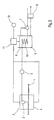
- Figur 1:
- eine schematische Darstellung einer Trockengruppe mit Reinigungsvorrichtung,
- Figur 2:
- eine andere Reinigungsvorrichtung mit Wärmetauscher 10 und
- Figur 3:
- eine schematische Darstellung eines Sammelbehälters 9.
Claims (12)
- Verfahren zur Reinigung eines endlos umlaufenden Bandes (1) in einer Maschine zur Herstellung und/oder Veredlung einer Papier-, Karton-, Tissueoder einer anderen Faserstoffbahn mit einer Reinigungsflüssigkeit (6), die auf das Band (1) aufgebracht und während und/oder nach der Reinigung gemeinsam mit gelösten Verunreinigungen zumindest in wesentlichem Umfang wieder abgeführt wird, dadurch gekennzeichnet, dass
wenigstens ein Teil der Verunreinigungen während der Abführung der Reinigungsflüssigkeit (6) von dieser getrennt und separat abgeführt wird. - Verfahren zur Reinigung eines endlos umlaufenden Bandes (1) in einer Maschine zur Herstellung und/oder Veredlung einer Papier-, Karton-, Tissueoder einer anderen Faserstoffbahn mit einer Reinigungsflüssigkeit (6), die auf das Band (1) aufgebracht und während und/oder nach der Reinigung gemeinsam mit gelösten Verunreinigungen zumindest in wesentlichem Umfang wieder abgeführt wird, insbesondere nach Anspruch 1, dadurch gekennzeichnet, dass
die Reinigungsflüssigkeit (6) in wenigstens einen Sammelbehälter (9) abgeführt wird. - Verfahren nach Anspruch 1 oder 2, dadurch gekennzeichnet, dass
die Reinigungsflüssigkeit (6) auf das Band (1) gesprüht wird. - Verfahren nach einem der vorhergehenden Ansprüche, dadurch gekennzeichnet, dass
die Reinigungsflüssigkeit (6) vom Band (1) abgesaugt wird. - Verfahren nach einem der Ansprüche 2 bis 4, dadurch gekennzeichnet, dass wenigstens ein Teil der Verunreinigungen im Sammelbehälter (9) mit Hilfe von Bindemitteln chemisch gebunden wird.
- Verfahren nach einem der Ansprüche 2 bis 5, dadurch gekennzeichnet, dass nach dem Absetzen der Verunreinigungen Reinigungsflüssigkeit (6) mit vermindertem Anteil an Verunreinigungen aus dem oberen Bereich des Sammelbehälters (9) abgeführt wird.
- Verfahren nach einem der vorhergehenden Ansprüche dadurch gekennzeichnet, dass
die Reinigungsflüssigkeit (6) vor dem Aufbringen auf das Band (1) erwärmt wird. - Verfahren nach Anspruch 7, dadurch gekennzeichnet, dass
die Wärmeenergie der Reinigungsflüssigkeit (6) während der Abführung und/oder im Sammelbehälter (9) zum Erwärmen der für die Reinigung des Bandes (1) vorgesehenen Reinigungsflüssigkeit (6) benutzt wird. - Vorrichtung zur Reinigung eines endlos umlaufenden Bandes (1) in einer Maschine zur Herstellung und/oder Veredlung einer Papier-, Karton-, Tissueoder einer anderen Faserstoffbahn mit einer Reinigungsflüssigkeit (6), die auf das Band (1) aufgebracht und während und/oder nach der Reinigung gemeinsam mit gelösten Verunreinigungen zumindest in wesentlichem Umfang wieder abgeführt wird, insbesondere zur Durchführung der Verfahren nach einem der vorhergehenden Ansprüche, dadurch gekennzeichnet, dass
die Reinigungsflüssigkeit (6) mit den Verunreinigungen in wenigstens einen Sammelbehälter (9) abgeführt wird. - Vorrichtung nach Anspruch 9, dadurch gekennzeichnet, dass
der Sammelbehälter (9) verfahrbar gestaltet ist. - Vorrichtung nach Anspruch 9 oder 10, dadurch gekennzeichnet, dass
der Sammelbehälter (9) zwischen 150 und 3600 l, vorzugsweise zwischen 300 und 1500 l Reinigungsflüssigkeit (6) aufnehmen kann. - Vorrichtung nach einem der Ansprüche 9 bis 11, dadurch gekennzeichnet, dass
der Sammelbehälter (9) einen Wärmetauscher (10) zur Aufwärmung der zur Reinigung vorgesehen Reinigungsflüssigkeit (6) besitzt.
Applications Claiming Priority (2)
| Application Number | Priority Date | Filing Date | Title |
|---|---|---|---|
| DE2003115606 DE10315606A1 (de) | 2003-04-05 | 2003-04-05 | Bandreinigung |
| DE10315606 | 2003-04-05 |
Publications (2)
| Publication Number | Publication Date |
|---|---|
| EP1464753A2 true EP1464753A2 (de) | 2004-10-06 |
| EP1464753A3 EP1464753A3 (de) | 2005-08-17 |
Family
ID=32842276
Family Applications (1)
| Application Number | Title | Priority Date | Filing Date |
|---|---|---|---|
| EP04101091A Withdrawn EP1464753A3 (de) | 2003-04-05 | 2004-03-17 | Bandreinigung |
Country Status (2)
| Country | Link |
|---|---|
| EP (1) | EP1464753A3 (de) |
| DE (1) | DE10315606A1 (de) |
Cited By (1)
| Publication number | Priority date | Publication date | Assignee | Title |
|---|---|---|---|---|
| WO2010103169A1 (en) * | 2009-03-09 | 2010-09-16 | Metso Paper, Inc. | Conditioning equipment for the fabric of a fiber web machine |
Family Cites Families (4)
| Publication number | Priority date | Publication date | Assignee | Title |
|---|---|---|---|---|
| DE2632241A1 (de) * | 1976-07-17 | 1978-01-19 | Paul Hammelmann | Vorrichtung zum austragen von ueber hin- und herbewegbare spritzrohre geloesten schadstoffen, schmutzteilchen o.dgl. |
| DE3413567A1 (de) * | 1984-04-11 | 1985-10-24 | Bayer Ag, 5090 Leverkusen | Papierhilfsmittel |
| DE4018074C2 (de) * | 1990-06-06 | 1995-09-14 | Voith Gmbh J M | Vorrichtung zum Reinigen eines umlaufenden Papiermaschinensiebes |
| FI117102B (fi) * | 1996-05-23 | 2006-06-15 | Metso Paper Inc | Menetelmä paperikoneella sen vesikiertojen järjestämiseksi |
-
2003
- 2003-04-05 DE DE2003115606 patent/DE10315606A1/de not_active Withdrawn
-
2004
- 2004-03-17 EP EP04101091A patent/EP1464753A3/de not_active Withdrawn
Cited By (1)
| Publication number | Priority date | Publication date | Assignee | Title |
|---|---|---|---|---|
| WO2010103169A1 (en) * | 2009-03-09 | 2010-09-16 | Metso Paper, Inc. | Conditioning equipment for the fabric of a fiber web machine |
Also Published As
| Publication number | Publication date |
|---|---|
| DE10315606A1 (de) | 2004-11-04 |
| EP1464753A3 (de) | 2005-08-17 |
Similar Documents
| Publication | Publication Date | Title |
|---|---|---|
| DE3005681C2 (de) | Verfahren und Vorrichtung zum Waschen einer aus Altpapier gewonnenen Faserstoffsuspension | |
| DE2758434A1 (de) | Filtereinrichtung | |
| EP0215392A2 (de) | Doppelbandpresse zur kontinuierlichen Herstellung kupferkaschierter Laminate | |
| DE1411905A1 (de) | Vorrichtung zum Entfernen von Fluessigkeit aus einer bewegten Papierbahn | |
| DE4213200A1 (de) | Flüssigkeitsfilter | |
| DE3126466A1 (de) | Siebmaschine | |
| DE69732524T2 (de) | Verfahren zur einrichtung des wasserkreislaufs in einer papiermaschine | |
| DE10331998A1 (de) | Vorrichtung zum Filtern von verunreinigten Flüssigkeiten, wie Kühlschmiermittel, insbesondere aus Werkzeugmaschinen | |
| DE10315606A1 (de) | Bandreinigung | |
| DE102011111454B4 (de) | Vorrichtung und Verfahren zur Filtration mit einem bandförmigen Filtermedium | |
| DE3245232C2 (de) | ||
| EP1100605B1 (de) | Eindicker | |
| DE20321567U1 (de) | Bandreinigung | |
| EP0863252B1 (de) | Verfahren und Vorrichtung zum Entwässern einer Faserstoffsuspension | |
| EP1342574B1 (de) | Filtereinrichtung für den Feuchtmittelkreislauf einer Offset-Druckmaschine | |
| DE2735548A1 (de) | Verfahren und vorrichtung zum reinigen von fluessigkeitsoberflaechen | |
| DE3020119A1 (de) | Verfahren und vorrichtung zum waschen von vakuumfiltrierbaren materialien, insbesondere papierfaserpulpe | |
| DE2816378A1 (de) | Verfahren und vorrichtung zur diskontinuierlichen vakuumbandfiltration von fluessigkeiten | |
| DE4013597C1 (en) | Dewatering of sludge - by pressing, thin pressing filtrate out of sludge layer, stacking then sludge layers on top of each other, etc. | |
| EP3014019A1 (de) | Pressenpartie für die entwässerung einer faserstoffbahn | |
| DE69715984T2 (de) | Apparat zur Herstellung eines Filtermediums in Blattform | |
| DE112010005105T5 (de) | Papierherstellungsvorrichtung und Papierherstellungsanlage | |
| DE2832710C3 (de) | Bandfilter | |
| DE2021389A1 (de) | Verfahren zum kontinuierlichen Entwassern von Suspensionen | |
| DE29915410U1 (de) | Vorrichtung zum Abtragen von Harzrückständen an einem metallischen Pressblech |
Legal Events
| Date | Code | Title | Description |
|---|---|---|---|
| PUAI | Public reference made under article 153(3) epc to a published international application that has entered the european phase |
Free format text: ORIGINAL CODE: 0009012 |
|
| AK | Designated contracting states |
Kind code of ref document: A2 Designated state(s): AT BE BG CH CY CZ DE DK EE ES FI FR GB GR HU IE IT LI LU MC NL PL PT RO SE SI SK TR |
|
| AX | Request for extension of the european patent |
Extension state: AL LT LV MK |
|
| PUAL | Search report despatched |
Free format text: ORIGINAL CODE: 0009013 |
|
| AK | Designated contracting states |
Kind code of ref document: A3 Designated state(s): AT BE BG CH CY CZ DE DK EE ES FI FR GB GR HU IE IT LI LU MC NL PL PT RO SE SI SK TR |
|
| AX | Request for extension of the european patent |
Extension state: AL LT LV MK |
|
| 17P | Request for examination filed |
Effective date: 20060217 |
|
| AKX | Designation fees paid |
Designated state(s): AT BE BG CH CY CZ DE DK EE ES FI FR GB GR HU IE IT LI LU MC NL PL PT RO SE SI SK TR |
|
| RAP1 | Party data changed (applicant data changed or rights of an application transferred) |
Owner name: VOITH PATENT GMBH |
|
| 17Q | First examination report despatched |
Effective date: 20070516 |
|
| STAA | Information on the status of an ep patent application or granted ep patent |
Free format text: STATUS: THE APPLICATION IS DEEMED TO BE WITHDRAWN |
|
| 18D | Application deemed to be withdrawn |
Effective date: 20071127 |