EP1464488B1 - Printing unit - Google Patents
Printing unit Download PDFInfo
- Publication number
- EP1464488B1 EP1464488B1 EP04100557A EP04100557A EP1464488B1 EP 1464488 B1 EP1464488 B1 EP 1464488B1 EP 04100557 A EP04100557 A EP 04100557A EP 04100557 A EP04100557 A EP 04100557A EP 1464488 B1 EP1464488 B1 EP 1464488B1
- Authority
- EP
- European Patent Office
- Prior art keywords
- printing
- pressure cylinder
- counter pressure
- drive
- printing unit
- Prior art date
- Legal status (The legal status is an assumption and is not a legal conclusion. Google has not performed a legal analysis and makes no representation as to the accuracy of the status listed.)
- Expired - Lifetime
Links
- 238000007639 printing Methods 0.000 title claims description 129
- 238000012546 transfer Methods 0.000 claims description 24
- 230000001105 regulatory effect Effects 0.000 claims description 7
- 230000009467 reduction Effects 0.000 claims description 6
- 230000005540 biological transmission Effects 0.000 abstract description 7
- 230000008901 benefit Effects 0.000 description 6
- 230000001172 regenerating effect Effects 0.000 description 5
- 238000000034 method Methods 0.000 description 4
- 230000008569 process Effects 0.000 description 3
- 230000008878 coupling Effects 0.000 description 2
- 238000010168 coupling process Methods 0.000 description 2
- 238000005859 coupling reaction Methods 0.000 description 2
- 238000011161 development Methods 0.000 description 2
- 230000006698 induction Effects 0.000 description 2
- 238000012545 processing Methods 0.000 description 2
- 230000001360 synchronised effect Effects 0.000 description 2
- 230000000712 assembly Effects 0.000 description 1
- 238000000429 assembly Methods 0.000 description 1
- 230000009286 beneficial effect Effects 0.000 description 1
- 238000013461 design Methods 0.000 description 1
- 230000004069 differentiation Effects 0.000 description 1
- 238000010017 direct printing Methods 0.000 description 1
- 230000000694 effects Effects 0.000 description 1
- 230000002349 favourable effect Effects 0.000 description 1
- 238000007645 offset printing Methods 0.000 description 1
- 230000002093 peripheral effect Effects 0.000 description 1
- 230000001737 promoting effect Effects 0.000 description 1
Images


Classifications
-
- B—PERFORMING OPERATIONS; TRANSPORTING
- B41—PRINTING; LINING MACHINES; TYPEWRITERS; STAMPS
- B41F—PRINTING MACHINES OR PRESSES
- B41F13/00—Common details of rotary presses or machines
- B41F13/004—Electric or hydraulic features of drives
- B41F13/0045—Electric driving devices
Definitions
- the invention relates to a printing unit with a drive of cylinders of the printing unit according to the features of claim 1.
- a drive of cylinders of a printing unit with a counter-pressure cylinder and a cooperating cylinder of a printing unit is known, wherein the two cylinders are driven by different drive motors.
- the motors are assigned to controllers to which setpoint values for the angular position or speed are specified by a setpoint generator and with which a current to be supplied to the motor is regulated.
- the DE 197 23 059 A1 discloses a drive of a printing unit, wherein a counter-pressure cylinder is assigned four printing units, and is mechanically driven independently of the printing units by a separate drive motor.
- two impression cylinders are each driven by a separate drive motor independently of four associated printing units.
- the DE 195 25 593 C2 discloses a multi-motor drive for a sheet-fed press, wherein the individual printing units are each driven by two drive motors on the transfer cylinder, namely by a high-dynamic engine low power and one with low dynamics and high performance.
- the inverters of the drives are connected to each other via a DC intermediate circuit in order to maintain the full DC voltage in case of power failure via the regenerated braking energy of the then regeneratively operated drives.
- the principle of the double engine arrangement on the transfer cylinder can also on each individually driven cylinder of the printing press are transmitted.
- the EP 0 669 208 A discloses a machine for processing a stream of individual carton blanks, wherein as processing units include two an impression cylinder and a co-acting pressure cylinder having printing units are provided.
- One of the two motors of two co-acting cylinders may be operated by a digital control unit as a slave of the other with respect to the desired relative angular position and speed. In one embodiment of a roller this is driven by two drive motors each end face.
- a counter-pressure cylinder via selectively switchable clutches on two drive motors can be coupled.
- WO 02/074540 A discloses a drive of cylinders of a printing unit, wherein a counter-pressure cylinder and a cooperating printing cylinder are mechanically driven independently by drive motors.
- drive controllers are assigned to the drive motors, to which setpoint values for the peripheral speed or speed are specified by a common control. The determination of the setpoint values to be specified takes place as a function of a detected power of the drive motor driving the counter-pressure cylinder and given to the control unit.
- the invention has for its object to provide a printing unit with a respect to a motor dimensioning and / or drive performance improved drive concept.
- the achievable with the present invention consist in particular that a drive power of a printing unit can be optimized and / or a favorable dimensioning the drive motors is enabled.
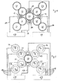
- a printing press in particular a web-fed rotary printing press, has at least one printing unit 01.
- the printing unit 01 has at least one cylinder 02, which is embodied as a counter-pressure cylinder 02, on which at least two cylinders 03 or 04, eg. B. several transfer cylinder 03 in the indirect printing process or multiple forme cylinder 04 in direct printing process can be adjusted.
- the impression cylinder 02 is designed as a satellite cylinder 02, the printing unit 01 as a satellite printing unit 01.
- the advantageous embodiment of the printing unit 01 as a nine-cylinder satellite printing unit 01 ensures a very good Passerhaltmaschine or a low fan-out. But it can also be designed as a ten-cylinder satellite printing unit 01.
- the printing unit 01 has several, in the example four printing units 06, by means of which ink from an inking unit 07 on the forme cylinder 04 on a the impression cylinder 02 looping web can be applied.
- the printing unit 06 is executed as an offset printing unit 06 for the wet offset and has in addition to the inking 07 a dampening 08 and a o.g. Transfer cylinder 03 on.
- the transfer cylinder 03 forms a pressure point with the impression cylinder 02.
- the forme cylinder 04 forms the pressure point with the impression cylinder 02.
- the same parts are given the same reference numerals, as far as they are not necessary for differentiation. However, a difference in the spatial position may exist and remains in the case of awarding the same reference i. d. R. unconsidered.
- the following drive and supply concepts are basically for all printing units 01 (for direct or indirect printing method) of advantage, in which a Impression cylinder 02 and at least one, in particular two, with this cooperating cylinder 03; 04 by different drive motors 09; 12 are driven. Particularly advantageous is the execution of the impression cylinder 02 with two drive motors 09 in conjunction with wide printing units 06, z. B. at least twice, in particular three times wide, ie for the pressure of four, in particular six axially juxtaposed newspaper pages.
- the forme cylinder 04 has z. B. a circumference between 900 and 1300 mm, in particular from 940 to 1200 mm.
- the scope is z. B. for receiving two stationary printed pages, z. B. newspaper pages in the broadsheet format, by means of two in the circumferential direction on the forme cylinder 04 successively fixable elevators, z. B. flexible printing forms formed.
- the printing plates can be mounted in the circumferential direction on the forme cylinder 04 and, for example, in each case individually replaceable as a single printing plate equipped with a printing side in the axial direction.
- a length of the usable bale of the forme cylinder 04 is z. B. 1,850 to 2,400 mm, in particular 1,900 to 2,300 mm and is in the axial direction for receiving z.
- the length of the usable bale is between 2,000 and 2,400 mm.
- the transfer cylinder 03 has in the exemplary embodiment also has a scope z. B. between 900 and 1300 mm, in particular from 940 to 1200 mm.
- the length of the usable bale of the transfer cylinder 03 is z. B. 1,850 to 2,400 mm, in particular 1,900 to 2,300 mm and is in the longitudinal direction of each other z. B. with three lifts, z. B. blankets, occupied. They extend in the circumferential direction substantially to the full extent.
- the blankets are beneficial to the vibration behavior of the printing unit in the operating case, advantageously alternating, z. B. by 180 °, offset from one another.
- the length of the usable bales also between 2,000 and 2,400 mm.
- a ratio of a length of the usable bale of the cylinders 03; 04 to the diameter should be 5.8 to 8.8, z. B. at 6.3 to 8.0, in a broader version but especially at 6.5 to 8.0.
- the length of the usable bale here is the width or length of the bale to understand, which is suitable for receiving elevators. This corresponds approximately to a maximum possible web width of a web to be printed. Based on an entire length of the bale of the cylinder 03; 04 would be added to this length of usable bale still the width of any existing bearer rings, possibly existing grooves and / or possibly existing lateral surface areas, which z. B. for the operation of clamping and / or clamping devices must be accessible.
- the impression cylinder 02 also essentially has the dimensions and ratios of at least the assigned transfer cylinder 03.
- a gear 11, in particular at least one reduction gear 11 is arranged between the drive motor 09 and the driven cylinder 02.
- the printing unit 01 is driven so that the printing units 06 each at least by one of the others Pressure units 06 and the impression cylinder 02 mechanically independent drive motor 12 are rotationally driven.
- the drive motors 12 are preferably as with respect to their angular position controlled electric motors 12, z. B. as induction motors, synchronous motors or DC motors.
- In an advantageous embodiment is between the drive motor 12 and the driven cylinder 03; 04 or cylinder pair 03, 04 at least one gear 13, in particular at least one reduction gear 62 (such as pinion, attachment and / or planetary gear) arranged.
- the individual drives contribute to high flexibility and to avoid vibrations in the mechanical drive system, and thus also to high quality in the product.
- Fig. 1 have form and transfer cylinder 03; 04 in pairs a common drive motor 11.
- the drive can be coaxial, z. B. via a gear 13, on one of the cylinder 03; 04 and from there to the other cylinder 04; 03 done or as explained in more detail below about a pinion and a drive wheel.
- the drive connection (shown as a connecting line) can be done as a gear connection or via belt.
- 04 is also a drive from the forme cylinder 04 without advantage of its own drive motor.
- the cylinders 02; 03; 04 represent in their respective pressure-on position friction gear. Between the cylinders 02; 03; 04 can, for. B. due to different conveying behavior and / or surface properties, a power exchange via the friction gear. For example, z. B. in so-called positive-promoting lifts on the transfer cylinder 03, the impression cylinder 02 be driven in one case on the transfer cylinder 03, wherein the drive motors 09 are then operated as a generator and the transfer cylinder 03 by motor. Conversely, z. B. in so-called. Negative promotional lifts on the transfer cylinder 03, the Counter-pressure cylinder 02, the transfer cylinder 03 to be driven with the drive motors 09 then motorized and the drive motors 12 are operated as a generator.
- the drive motors 09; 12 of the printing unit 01 are connected via at least one supply unit 17, z. B. power supplies 17, supplied with electrical power. This is done, for example, from the supply unit 17 via lines 19 to a respective drive motor 09; It is essential that the two drive motors 09 are supplied with electrical power by at least one supply unit 17, by means of which at least one drive motor 12 of a printing unit 06 is also supplied. This ensures that energy generated by regenerative operation does not have to be completely destroyed by heat, but can be fed back into the respective other drive.
- the risk of overload (in regenerative and / or motor operation) of the supply units 17 is significantly reduced, since at significant power exchange via the friction gear always a power between a printing unit 06 and the impression cylinder 02 is moved, which on the common supply unit 17 again at least partly traceable.
- the drive motors 09; 12 of the printing unit 01 are supplied via several, here two supply units 17, it is of particular advantage that the impression cylinder 02 is driven by two drive motors 09.
- the two drive motors 09 are supplied with electrical power by various supply units 17, by means of which in each case at least one drive motor 12 of a printing unit 06 is also supplied.
- the controllers 18 and controls 18 are in addition to the electrical energy of a Control device 21, which has, for example, a virtual (electronic) master axis or represents transmitted signals to a desired angular position and / or target speed.
- the controller 18 then regulate z. B. according to this setpoint specification, the power supply (motor) or -abbow (regenerative, braking effect).
- FIG. 2 to 5 Various advantageous drive configurations are shown on a nine-cylinder printing unit 01.
- each printing unit 03 each have mutually meshing drive wheels 22; 23 (eg gears 22, 23) and are driven via a pinion 24 by a common drive motor 12 on the transfer cylinder 03.
- the drive can also coaxial, z. B. via an unillustrated, og attachment gear, done.
- From the drive wheel of the transfer cylinder 17 is then on the drive wheel 23 of the forme cylinder 03, and possibly from there to the inking and / or dampening unit 07; 08 driven.
- the drive connection between the two cylinders 03; 04 can also be done via belt.
- the counter-pressure cylinder 02 is here driven by the two drive motors 09 via pinion 26, which drives on a common drive wheel 27 or on two different axially mutually offset drive wheels 27 of the impression cylinder 02. Between the drive motors 09; 12 and the drive wheels 22; 27 can still further transmission elements, such. As gears and / or belt drives, may be provided.
- the drive assembly is of particular advantage in terms of a clear moment flow in the printing unit 06 from the transfer cylinder 03 to the forme cylinder 04 and then eg color and possibly dampening unit 07; 08.
- the power supply is designed such that the drive motors 12 of the left printing units 06 are supplied together with a drive motor 09 of the impression cylinder 02 by a power supply unit 17 and the rest by the other power supply unit 17.
- the drive arrangement is of particular advantage with regard to an adjusting movement of the transfer cylinder 03, without therefore a high cost in the storage of the drive motor 12 and / or compromises in the gear engagement would have to be considered.
- the power supply is exemplarily designed such that the drive motors 12 of the upper printing units 06 are supplied together with a drive motor 09 of the impression cylinder 02 by a power supply 17 and the rest by the other power supply 17.
- the supply scheme off Fig. 3 can on the drive concept of Fig. 2 applied and vice versa.
- Fig. 4 In each case two pairs 03, 04 are driven together in a drive network by a drive motor. It is driven by the two transfer cylinders 03 to "outside" (torque flow). In a variant not shown may be driven by one of the two forme cylinder 04 of the drive assembly, wherein between the drive wheels 22 of the transfer cylinder 03 is provided at least one intermediate.
- the drive wheel 27 and the drive wheels 27 are as to Fig. 2 described driven.
- the concept provides for the supply of a respective drive motor 09 together with one of the drive motors 12 of the two drive assemblies.
- cylinders have 03; 04 of the printing units 06 each have their own drive motor 12, which, for. B. each have a not shown, coaxial (Intentional) gearbox, substantially coaxial with the cylinder 03; 04 drives.
- the drive by the drive motor 12 can not coaxial in the above-mentioned manner, but via pinion 24 or belt drives on drive wheels 22; 23 done.
- the impression cylinder 02 is again driven by means of the two drive motors 09.
- the inking unit 07 shown above has, among other, not designated rolls z. B.
- the inking unit may also have only a distribution cylinder.
- the above applies to the drive of the dampening unit 08 in the same way.
- the concept provides for the supply of the drive motors 12 of two printing units 06 together with a drive motor 09 of the impression cylinder 02.
- Fig. 6 shows a side view of the drive for the impression cylinder in the embodiment with a rotationally rigidly connected to the impression cylinder 02 drive wheel 27. On this is by a respective drive motor 09, z. B. via an auxiliary gear 11, and a pinion 26 driven.
- the two pinions 26 drive on two axially offset drive wheels 27th
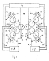
- Fig. 7 shows a satellite printing unit 01 with two satellite cylinders 02, which are each associated with two printing units 06.
- each of the two impression cylinders 02 has its own drive motor 09.
- Drive motor 09 and the cylinder 02 is o.
- the too off Fig. 2 to 5 described supply concepts of the drive motors 09; 12 and the drive concepts of the printing units 06 are applicable here.
- the only difference to the above examples is that the corresponding Fig. 2 to 5 supplied drive motors 09 not on the same impression cylinder 02, but drive on two different impression cylinder 02.
- two drive motors 09 are provided per impression cylinder 02.
- the supply concepts are the FIGS. 2 to 5 be applied so that the two associated drive motors 09 each a supply unit 17 and the other two of the other supply unit 17 are added.
- the drive motors 12 are preferably as with respect to their angular position controlled electric motors 12, z. B. as induction motors, synchronous motors or DC motors.
- the two drive motors 09 can also be designed in this way. This is especially true if as in Fig. 7 two counter-pressure cylinders 02 each have a drive motor 09 is assigned.
- an impression cylinder 02 has two drive motors 09, it is advantageous if one of the two drive motors 09 is regulated with respect to its angular position, and the other drive motor with respect to its moment (or its output).
- the angular position-controlled drive motor 09 acts here z. B. as "master”, while the other drive motor 09 is tracked as a "slave” torque-controlled.
- the supply unit 17 is - as well as the two above-described supply units 17 - designed to lead from regenerative drive drive power derived at least to a significant extent in the drive power for the motor drive back.
- a named power supply 17 for supplying several drives in the manner described has, for example, a power supply from a local network (printing or energy supplier), through which only energy is fed into the power supply unit, but can not be fed back from this.
- a generator-operated drive without dispensing possibility to a consumer would possibly overheat.
- each operating motor (pressure-on) operated in generator mode is drive 09; 12 (in particular 09) of a same printing unit at least one drive motor 12 which is operated by a motor during operation; 09 assigned via the common power supply 17.
Abstract
Description
Die Erfindung betrifft eine Druckeinheit mit einem Antrieb von Zylindern der Druckeinheit gemäß den Merkmalen des Anspruches 1.The invention relates to a printing unit with a drive of cylinders of the printing unit according to the features of
Durch die
In der
Die
Durch die
Die
In der
Durch die
Der Erfindung liegt die Aufgabe zugrunde, eine Druckeinheit mit einem hinsichtlich einer Motorendimensionierung und/oder einer Antriebsleistung verbessertem Antriebskonzept zu schaffen.The invention has for its object to provide a printing unit with a respect to a motor dimensioning and / or drive performance improved drive concept.
Die Aufgabe wird erfindungsgemäß durch die Merkmale des Anspruchs 1 gelöst.The object is achieved by the features of
Die mit der Erfindung erzielbaren Vorteile bestehen insbesondere darin, dass eine Antriebsleistung einer Druckeinheit optimierbar und/oder eine günstige Dimensionierung der Antriebsmotoren ermöglicht wird.The achievable with the present invention consist in particular that a drive power of a printing unit can be optimized and / or a favorable dimensioning the drive motors is enabled.
Durch zwei einem Gegendruckzylinder zugeordnete Antriebsmotoren wird, insbesondere für breite Zylinder, die Verwendung von Antriebsmotoren ermöglicht, welche auch für die Zylinderpaare einsetzbar sind. Die Versorgung der beiden Antriebsmotoren über Netzgeräte, welche auch mindestens einen Antrieb eines Druckwerkes versorgen, gewährleistet eine zumindest teilweise Rückführung von durch Reibgetriebe übertragener Energie. Von Vorteil ist eine Ausführung, wobei die beiden Antriebsmotoren jeweils verschiedenen Netzgeräten zugeordnet sind, welche jedoch gleichzeitig zumindest jeweils dem Antrieb eines Zylinderpaares zugeordnet sind.By two drive cylinders associated with a counter-pressure cylinder, the use of drive motors, in particular for wide cylinders, which can also be used for the cylinder pairs, is made possible. The supply of the two drive motors via power supplies, which also supply at least one drive of a printing unit, ensures at least partial return of energy transmitted through friction gear. An advantage is an embodiment, wherein the two drive motors are each assigned to different power supplies, which are, however, at least each associated with the drive of a pair of cylinders at the same time.
Ausführungsbeispiele der Erfindung sind in den Zeichnungen dargestellt und werden im folgenden näher beschrieben.Embodiments of the invention are illustrated in the drawings and will be described in more detail below.
Es zeigen:
- Fig. 1
- eine Neunzylinder-Satelliten-Druckeinheit;
- Fig. 2
- ein erstes Ausführungsbeispiel für den Antrieb und die Versorgung;
- Fig. 3
- ein zweites Ausführungsbeispiel für den Antrieb und die Versorgung;
- Fig. 4
- ein drittes Ausführungsbeispiel für den Antrieb und die Versorgung;
- Fig. 5
- ein viertes Ausführungsbeispiel für den Antrieb und die Versorgung;
- Fig. 6
- eine seitliche Darstellung des Antriebes für den Gegendruckzylinder;
- Fig. 7
- eine Zehn-Satelliten-Druckeinheit.
- Fig. 1
- a nine cylinder satellite printing unit;
- Fig. 2
- a first embodiment of the drive and the supply;
- Fig. 3
- a second embodiment of the drive and the supply;
- Fig. 4
- a third embodiment for the drive and the supply;
- Fig. 5
- a fourth embodiment for the drive and the supply;
- Fig. 6
- a side view of the drive for the impression cylinder;
- Fig. 7
- a ten-satellite printing unit.
Eine Druckmaschine, insbesondere eine Rollenrotationsdruckmaschine, weist mindestens eine Druckeinheit 01 auf. Die Druckeinheit 01 weist mindestens einen als Gegendruckzylinder 02 ausgeführten Zylinder 02, auf, an welchen zumindest zwei Zylinder 03 oder 04, z. B. mehrere Übertragungszylinder 03 im indirekten Druckverfahren oder mehrere Formzylinder 04 im direkten Druckverfahren anstellbar sind. Der Gegendruckzylinder 02 ist als Satellitenzylinder 02, die Druckeinheit 01 als Satellitendruckeinheit 01 ausgeführt.A printing press, in particular a web-fed rotary printing press, has at least one
Die vorteilhafte Ausführung der Druckeinheit 01 als Neunzylinder-Satelliten-Druckeinheit 01 gewährleistet eine sehr gute Passerhaltigkeit bzw. einen geringen Fan-Out. Sie kann aber auch als Zehnzylinder-Satelliten-Druckeinheit 01 ausgeführt sein.The advantageous embodiment of the
Die Druckeinheit 01 weist mehrere, im Beispiel vier Druckwerke 06 auf, mittels welchem Farbe von einem Farbwerk 07 über den Formzylinder 04 auf eine den Gegendruckzylinder 02 umschlingende Bahn aufbringbar ist. Im vorliegenden Beispiel ist das Druckwerk 06 als Offsetdruckwerk 06 für den Naßoffset ausgeführt und weist zusätzlich zum Farbwerk 07 ein Feuchtwerk 08 und einen o.g. Übertragungszylinder 03 auf. Der Übertragungszylinder 03 bildet mit dem Gegendruckzylinder 02 eine Druckstelle. Im direkten Verfahren bildet der Formzylinder 04 mit dem Gegendruckzylinder 02 die Druckstelle. Die gleichen Teile erhalten, soweit zur Unterscheidung nicht erforderlich, die selben Bezugszeichen. Ein Unterschied in der räumlichen Lage kann jedoch bestehen und bleibt im Falle der Vergabe gleicher Bezugszeichen i. d. R. unberücksichtigt.The
Die nachfolgenden Antriebs- und Versorgungskonzepte sind grundsätzlich für alle Druckeinheiten 01 (für direkte oder indirekte Druckverfahren) von Vorteil, bei welchen ein Gegendruckzylinder 02 und mindestens ein, insbesondere zwei, mit diesem zusammen wirkende Zylinder 03; 04 durch verschiedene Antriebsmotoren 09; 12 angetrieben sind. Insbesondere von Vorteil ist die Ausführung des Gegendruckzylinders 02 mit zwei Antriebsmotoren 09 in Verbindung mit breiten Druckeinheiten 06, z. B. zumindest doppelt, insbesondere dreifach breit, d. h. für den Druck von jeweils vier, insbesondere sechs axial nebeneinander angeordneten Zeitungsseiten.The following drive and supply concepts are basically for all printing units 01 (for direct or indirect printing method) of advantage, in which a
Der Formzylinder 04 besitzt z. B. einen Umfang zwischen 900 und 1.300 mm, insbesondere von 940 bis 1.200 mm. Der Umfang ist z. B. zur Aufnahme zweier stehenden Druckseiten, z. B. Zeitungsseiten im Broadsheetformat, mittels zweier in Umfangsrichtung auf den Formzylinder 04 hintereinander fixierbarer Aufzüge, z. B. flexibler Druckformen, ausgebildet. Die Druckformen sind in Umfangsrichtung auf dem Formzylinder 04 montierbar und beispielsweise jeweils als in axialer Richtung mit einer Druckseite bestückte Einzeldruckplatte einzeln austauschbar. Eine Länge des nutzbaren Ballens des Formzylinders 04 beträgt z. B. 1.850 bis 2.400 mm, insbesondere 1.900 bis 2.300 mm und ist in axialer Richtung zur Aufnahme von z. B. mindestens sechs nebeneinander angeordneten stehenden Druckseiten, insbesondere Zeitungsseiten im Broadsheetformat, bemessen. Dabei ist es u. a. von der Art des herzustellenden Produktes abhängig, ob jeweils nur eine Druckseite oder mehrere Druckseiten in axialer Richtung nebeneinander auf einer Druckform angeordnet sind. In einer noch breiteren Variante der Ausführung ist die Länge des nutzbaren Ballens zwischen 2.000 und 2.400 mm.The
Der Übertragungszylinder 03 besitzt in der beispielhaften Ausführung ebenfalls einen Umfang z. B. zwischen 900 und 1.300 mm, insbesondere von 940 bis 1.200 mm. Die Länge des nutzbaren Ballens des Übertragungszylinders 03 beträgt z. B. 1.850 bis 2.400 mm, insbesondere 1.900 bis 2.300 mm und ist in Längsrichtung nebeneinander z. B. mit drei Aufzügen, z. B. Gummitüchern, belegt. Sie reichen in Umfangsrichtung im wesentlichen um den vollen Umfang. Die Gummitücher sind, das Schwingungsverhalten des Druckwerkes im Betriebsfall günstig beeinflussend, vorteilhaft alternierend, z. B. um 180°, zueinander versetzt angeordnet. In der breiteren Variante ist die Länge des nutzbaren Ballens ebenfalls zwischen 2.000 und 2.400 mm.The
Ein Verhältnis einer Länge des nutzbaren Ballens der Zylinder 03; 04 zu deren Durchmesser sollte bei 5,8 bis 8,8 liegen, z. B. bei 6,3 bis 8,0, in breiter Ausführung jedoch insbesondere bei 6,5 bis 8,0.A ratio of a length of the usable bale of the
Als Länge des nutzbaren Ballens ist hier diejenige Breite bzw. Länge des Ballens zu verstehen, welche zur Aufnahme von Aufzügen geeignet ist. Dies entspricht in etwa auch einer maximal möglichen Bahnbreite einer zu bedruckenden Bahn. Bezogen auf eine gesamte Länge des Ballens der Zylinder 03; 04 wäre zu dieser Länge des nutzbaren Ballens noch die Breite von ggf. vorhandenen Schmitzringen, von ggf. vorhandenen Nuten und/oder von ggf. vorhandenen Mantelflächenbereichen hinzuzurechnen, welche z. B. zur Bedienung von Spann- und/oder Klemmvorrichtungen zugänglich sein müssen.The length of the usable bale here is the width or length of the bale to understand, which is suitable for receiving elevators. This corresponds approximately to a maximum possible web width of a web to be printed. Based on an entire length of the bale of the
In vorteilhafter Ausführung weist der Gegendruckzylinder 02 ebenfalls im wesentlichen die genannten Abmessungen und Verhältnisse zumindest des zugeordneten Übertragungszylinders 03 auf.In an advantageous embodiment, the
Der rotatorische Antrieb der Druckeinheit 01 erfolgt nun in der Weise, dass der Gegendruckzylinder 02 der Druckeinheit 01 mechanisch unabhängig von den Zylindern 03; 04 der Druckwerke 06 angetrieben ist. Weist die Druckeinheit 01 wie in
In einer in
In
Die Zylinder 02; 03; 04 stellen in ihrer jeweiligen Druck-An-Stellung Reibgetriebe dar. Zwischen den Zylindern 02; 03; 04 kann, z. B. aufgrund verschiedenen Förderverhaltens und/oder Oberflächeneigenschaften, ein Leistungsaustausch über die Reibgetriebe erfolgen. Beispielsweise kann, z. B. bei sog. positiv fördernden Aufzügen auf dem Übertragungszylinder 03, der Gegendruckzylinder 02 in einem Fall über die Übertragungszylinder 03 mit angetrieben sein, wobei dessen Antriebsmotoren 09 dann generatorisch und die der Übertragungszylinder 03 motorisch betrieben sind. Umgekehrt kann, z. B. bei sog. negativ fördernden Aufzügen auf dem Übertragungszylinder 03, der Gegendruckzylinder 02 die Übertragungszylinder 03 mit antreiben sein, wobei dessen Antriebsmotoren 09 dann motorisch und die Antriebsmotoren 12 generatorisch betrieben sind.The
Die Antriebsmotoren 09; 12 der Druckeinheit 01 werden über mindestens eine Versorgungseinheit 17, z. B. Netzgeräte 17, mit elektrischer Leistung versorgt. Dies erfolgt beispielsweise von der Versorgungseinheit 17 über Leitungen 19 zu einem dem jeweiligen Antriebsmotor 09; 12 zugeordneten Regler 18 bzw. einer Steuerung 18. Wesentlich ist es, dass die beiden Antriebsmotoren 09 durch mindestens eine Versorgungseinheit 17 mit elektrischer Leistung versorgt wird, durch welche auch mindestens ein Antriebsmotor 12 eines Druckwerkes 06 versorgt wird. Somit ist gewährleistet, dass eine durch generatorischen Betrieb gewonnene Energie nicht gänzlich über Wärme vernichtet werden muss, sondern in den jeweiligen anderen Antrieb rückgespeist werden kann. Auch die Gefahr einer Überlast (im generatorischen oder/und im motorischen Betrieb) der Versorgungseinheiten 17 ist deutlich verringert, da bei signifikantem Leistungsaustausch über das Reibgetriebe immer eine Leistung zwischen einem Druckwerk 06 und dem Gegendruckzylinder 02 verschoben wird, welche über die gemeinsame Versorgungseinheit 17 wieder zumindest zum Teil rückführbar ist.The
Für den Fall, dass die Antriebsmotoren 09; 12 der Druckeinheit 01 über mehrere, hier zwei Versorgungseinheiten 17 versorgt werden, ist es von besonderem Vorteil, dass der Gegendruckzylinder 02 durch zwei Antriebsmotoren 09 angetrieben ist. Die beiden Antriebsmotoren 09 werden durch verschiedene Versorgungseinheiten 17 mit elektrischer Leistung versorgt, durch welche jeweils auch mindestens ein Antriebsmotor 12 eines Druckwerkes 06 versorgt wird. Somit ist es für beide Versorgungseinheiten 17 gewährleistet, dass eine durch generatorischen Betrieb gewonnene Energie nicht gänzlich über Wärme vernichtet werden muss, sondern in den jeweiligen anderen Antrieb rückgespeist werden kann. Auch hier ist die Gefahr einer Überlast der Versorgungseinheiten 17 aus o.g. Gründen deutlich verringert.In the event that the
Den Reglern 18 bzw. Steuerungen 18 werden neben der elektrischen Energie von einer Steuereinrichtung 21, welche beispielsweise eine virtuelle (elektronische) Leitachse aufweist oder darstellt, Signale zu einer Soll-Winkellage und/oder Soll-Drehzahl übermittelt. Die Regler 18 regeln dann z. B. entsprechend dieser Sollwertvorgabe die Leistungszufuhr (motorisch) bzw. -abfuhr (generatorisch, Bremswirkung).The
In den folgenden
Die beiden in
Im Gegensatz zu
In einer Weiterbildung der Ausführung nach
Im Beispiel nach
In
Die in den Beispielen zu
Die zu aus
The too off
In einer Weiterbildung, insbesondere geeignet für breite Druckeinheiten (s.o.), sind je Gegendruckzylinder 02 zwei Antriebsmotoren 09 vorgesehen. In diesem Fall sind die Versorgungskonzepte der
In den Ausführungsbeispielen sind die Antriebsmotoren 12 vorzugsweise als bezüglich ihrer Winkellage geregelte Elektromotoren 12, z. B. als Asynchronmotoren, Synchronmotoren oder Gleichstrommotoren, ausgeführt. Auch die beiden Antriebsmotoren 09 können derart ausgeführt sein. Dies gilt insbesondere, wenn wie in
Weist ein Gegendruckzylinder 02 jedoch zwei Antriebsmotoren 09 auf, so ist es von Vorteil, wenn einer der beiden Antriebsmotoren 09 bzgl. seiner Winkellage geregelt ist, und der andere Antriebsmotor bzgl. seinem Moment (bzw. seiner Leistung). Der winkellagegeregelte Antriebsmotor 09 fungiert hierbei z. B. als "Master", während der andere Antriebsmotor 09 als "Slave" momentengeregelt nachgeführt wird.However, if an
In einer Weiterbildung der Energierückführung der aus den Reibgetrieben entstehenden Leistungsflüsse, weisen alle Antriebsmotoren 09; 12 der Zylinder 02; 03; 04 der Druckeinheit 01 eine gemeinsame Versorgungseinheit 17 auf. Die Versorgungseinheit 17 ist - wie auch die beiden vorbeschriebenen Versorgungseinheiten 17 - dazu ausgebildet, aus generatorischem Antrieb gewonnene Antriebsleistung zumindest zu einem signifikanten Teil in die Antriebsleistung für den motorischen Antrieb zurück zu führen. Ein genanntes Netzgerät 17 zur Versorgung mehrerer Antriebe in beschriebener Weise weist beispielsweise eine Energiezufuhr aus einem örtlichen Netz (Druckerei oder Energieversorger) auf, durch welches lediglich Energie in das Netzgerät gespeist, jedoch nicht aus diesem rückspeisbar ist. Je einem (oder mehreren gemeinsam) unabhängig von anderen Antrieben drehzahl- und/oder lagezuregelnden Antriebsmotor 09; 11 weist das Netzgerät 17 beispielsweise einen Umrichter (insbesondere Frequenzumrichter) auf, deren Leistungsbedarf aus einem gemeinsamen Stromkreis gespeist wird. Elektrische Energie, welche aus einem generatorisch betriebenen Antriebsmotor 09; 12 zurückfließt, kann auf diesem Wege einem motorisch betriebeben Antriebsmotor 12; 09 zugeführt werden. Diese Energie wird daher nicht allein in Wärme verwandelt, sondern einem anderen Verbraucher zur Verfügung gestellt. Ein generatorisch betriebener Antrieb ohne Abgabemöglichkeit an einen Verbraucher würde ggf. überhitzen.In a refinement of the energy return of the power flows arising from the friction gears, all drive
Zumindest ist in einer vorteilhaften Ausführung jedem im Betrieb (Druck-An) generatorisch betriebenen Antriebsmotor 09; 12 (insbesondere 09) einer selben Druckeinheit mindestens ein im Betrieb motorisch betriebener Antriebsmotor 12; 09 über das gemeinsame Netzgerät 17 zugeordnet. In besonders vorteilhafter Ausführung sind sämtliche Antriebsmotoren 09; 11 einer Druckeinheit 01 - insbesondere Neunzylinderdruckeinheit 01 - über ein gemeinsames Netzgerät 17 in der Weise miteinander verbunden, dass von dem oder den generatorisch in Druck-An betriebenen Antriebsmotoren 09; 12 zumindest ein signifikanter Anteil der Leistung zum Antrieb des oder der motorisch betriebenen Antriebsmotoren 12; 09 zugeführt ist. Von einem generatorisch betriebenen Antriebsmotor 09; 12 fließ somit Energie, z. B. Antriebsenergie, insbesondere elektrische Energie, über das Netzgerät 17 in den motorisch betriebenen Antriebsmotor 12; 09.At least, in an advantageous embodiment, each operating motor (pressure-on) operated in generator mode is drive 09; 12 (in particular 09) of a same printing unit at least one
- 0101
- Druckeinheit, Neun- bzw. Zehnzylinder-Satelliten-DruckeinheitPrinting unit, nine- or ten-cylinder satellite printing unit
- 0202
- Zylinder, GegendruckzylinderCylinder, impression cylinder
- 0303
- Zylinder, ÜbertragungszylinderCylinder, transfer cylinder
- 0404
- Zylinder, FormzylinderCylinder, forme cylinder
- 0505
- --
- 0606
- Druckwerkprinting unit
- 0707
- Farbwerkinking
- 0808
- Feuchtwerkdampening
- 0909
- Antriebsmotordrive motor
- 1010
- --
- 1111
- Getriebe, UntersetzungsgetriebeTransmission, reduction gear
- 1212
- Antriebsmotordrive motor
- 1313
- Getriebe, UntersetzungsgetriebeTransmission, reduction gear
- 1414
- Antriebsmotordrive motor
- 1515
- --
- 1616
- Antriebsmotordrive motor
- 1717
- Versorgungseinheit, NetzgerätSupply unit, power supply
- 1818
- Regler, SteuerungController, control
- 1919
- Leitungmanagement
- 2020
- --
- 2121
- Steuereinrichtungcontrol device
- 2222
- Antriebsrad, ZahnradDrive wheel, gear
- 2323
- Antriebsrad, ZahnradDrive wheel, gear
- 2424
- Ritzelpinion
- 2525
- --
- 2626
- Ritzelpinion
- 2727
- Antriebsrad, ZahnradDrive wheel, gear
Claims (21)
- Printing unit comprising a drive of cylinders (02; 03; 04) of the printing unit (01) and comprising at least one supply unit (17) for supplying drive motors (09; 12) of the printing unit (01) with electric power, a counter pressure cylinder (02) of the printing unit (01) and at least one cylinder (03; 04) cooperating with said counter pressure cylinder and belonging to a printing couple (06) coordinated with the counter pressure cylinder (02) being driven mechanically independently of one another by different drive motors (09; 12), in each case regulators (18) to which signals relating to a required angular position and/or required rotational speed can be transmitted from a control device (21) and which regulate a power supply or removal according to this required value specification being coordinated with the drive motors (09), the counter pressure cylinder (02) being driveable simultaneously by two drive motors (09) mechanically independently of the cooperating cylinder (03; 04), and both the regulator (18) of at least one drive motor (09) of the counter pressure cylinder (02) and the regulator (18) of the drive motor (12) of the at least one cooperating cylinder (03; 04) being supplied with electric power, the at least one supply unit (17) being formed for feeding back drive power obtained from driving of one of the drive motors (09; 12) as a generator at least partly into the drive power for the motor drive of another of the drive motors (09; 12).
- Printing unit according to Claim 1, characterized in that the printing unit (01) has at least two cylinders (03; 04) of two printing couples (06), which cylinders are coordinated with the counter pressure cylinder (02).
- Printing unit according to Claim 1, characterized in that, during operation of the printing unit (01), one of the two drive motors (09; 12) supplied together via the supply unit (17) is operated as a generator and the other as a motor in such a way that, via the common supply unit (17), energy delivered back from the drive motor (09; 12) operated as a generator flows to the drive motor (12; 09) operated as a motor.
- Printing unit according to Claim 2, characterized in that all rotational drive motors (09; 12) of cylinders (02; 03; 04) of the printing unit (01) are supplied with energy via a common supply unit (17).
- Printing unit according to Claim 2, characterized in that at least one drive motor (09) of the counter pressure cylinder (02) and a drive of at least one printing couple (06) coordinated with the counter pressure cylinder (02) are supplied with energy via a first supply unit (17) and at least one other drive motor (09) of the counter pressure cylinder (02) and a drive of at least one other printing couple (06) coordinated with the counter pressure cylinder (02) are supplied with energy via a second supply unit (17) differing from the first supply unit (17).
- Printing unit according to Claim 1, characterized in that the printing couples (06) coordinated with the counter pressure cylinder (02) have at least one cylinder (03; 04) cooperating with the counter pressure cylinder (02).
- Printing unit according to Claim 1, characterized in that the printing couples (06) coordinated with the counter pressure cylinder (02) have a transfer cylinder (03) cooperating with the counter pressure cylinder (02) and have a coordinated forme cylinder (04).
- Printing unit according to Claim 6 or 7, characterized in that the cylinders (03; 04) of two printing couples (06) coordinated with the counter pressure cylinder (02) have a common drive motor (12).
- Printing unit according to Claim 6 or 7, characterized in that the cylinders (03; 04) of each printing couple (06) coordinated with the counter pressure cylinder (02) have at least one drive motor (12) mechanically independent of other printing couples (06) coordinated with the counter pressure cylinder (02) and mechanically independent of the counter pressure cylinder (02).
- Printing unit according to Claim 9, characterized in that the cylinders (03; 04) of the printing couple (06) coordinated with the counter pressure cylinder (02) are mechanically coupled for driving and are driven in pairs by a common drive motor (12) mechanically independently of other cylinders (02, 03; 04).
- Printing unit according to Claim 9, characterized in that the cylinders (03; 04) of the printing couple (06) coordinated with the counter pressure cylinder (02) are in each case driven by a separate drive motor (12) mechanically independently of one another.
- Printing unit according to Claim 1, characterized in that, in the case of a nine-cylinder printing unit, the drives of two of the four printing couples (06) coordinated with the counter pressure cylinder (02) are supplied with energy together with the drive motor (09) of the counter pressure cylinder (02) by a supply unit (17) and the drives of the other two printing couples (06) are supplied with energy by a further supply unit (17).
- Printing unit according to Claim 1, characterized in that, in the case of a nine-cylinder printing unit, in each case the drives of two of the four printing couples (06) coordinated with the counter pressure cylinder (02) and one of the drive motors (09) of the counter pressure cylinder (02) are supplied with electric energy by a supply unit (17).
- Printing unit according to Claim 1, characterized in that, in the case of a ten-cylinder satellite printing unit, in each case the drives of two of the four printing couples (06) coordinated with the counter pressure cylinder (02) and one of the drive motors (09) of the counter pressure cylinder (02) are supplied with electric energy by a common supply unit (12).
- Printing unit according to Claim 1, 8, 9, 10 or 11, characterized in that the cylinder (03; 04) of the printing couple (06) coordinated with the counter pressure cylinder (02) is driven from the drive motor (12) via a gear (13), in particular a reduction gear (13).
- Printing unit according to Claim 1, characterized in that the counter pressure cylinder (02) is driven from the drive motor (09) via a gear (11), in particular a reduction gear (11).
- Printing unit according to Claim 1, 8, 9, 10 or 11, characterized in that the drive motor (12) for the cylinders (03; 04) of the printing couple (06) coordinated with the counter pressure cylinder (02) is in the form of an electric motor which can be regulated with respect to its angular position.
- Printing unit according to Claim 1, characterized in that at least one of the two drive motors (09) of the counter pressure cylinder (09) is in the form of an electric motor which can be regulated with respect to its angular position.
- Printing unit according to Claim 1, characterized in that one of two drive motors (09) driving the same counter pressure cylinder (02) is in the form of an electric motor which can be regulated with respect to its angular position and the other is in the form of an electric motor which can be regulated with respect to an applied moment.
- Printing unit according to Claim 1, characterized in that the printing unit is in the form of a printing unit of a web-fed rotary printing press in which the counter pressure cylinder (02) is coordinated with one or more printing couples (06) via a web on which printing is to be effected.
- Printing unit according to Claim 1, characterized in that the supply unit (17) for the two drive motors (09; 12) to be regulated with respect to speed and/or position has a converter whose power requirement is supplied from a common circuit.
Applications Claiming Priority (2)
| Application Number | Priority Date | Filing Date | Title |
|---|---|---|---|
| DE10309092A DE10309092B3 (en) | 2003-03-03 | 2003-03-03 | Drive mechanism for cylinders of printing machine, has several motors driving different groups of cylinders and connected to two separate electrical power supplies |
| DE10309092 | 2003-03-03 |
Publications (3)
| Publication Number | Publication Date |
|---|---|
| EP1464488A2 EP1464488A2 (en) | 2004-10-06 |
| EP1464488A3 EP1464488A3 (en) | 2008-10-29 |
| EP1464488B1 true EP1464488B1 (en) | 2010-04-28 |
Family
ID=32842095
Family Applications (1)
| Application Number | Title | Priority Date | Filing Date |
|---|---|---|---|
| EP04100557A Expired - Lifetime EP1464488B1 (en) | 2003-03-03 | 2004-02-13 | Printing unit |
Country Status (3)
| Country | Link |
|---|---|
| EP (1) | EP1464488B1 (en) |
| AT (1) | ATE465872T1 (en) |
| DE (2) | DE10309092B3 (en) |
Families Citing this family (8)
| Publication number | Priority date | Publication date | Assignee | Title |
|---|---|---|---|---|
| US7383771B2 (en) * | 2003-12-05 | 2008-06-10 | Man Roland Druckmaschinen Ag | Web-fed rotary printing unit |
| DE102006003005B3 (en) * | 2005-06-17 | 2006-11-23 | Koenig & Bauer Ag | Press for flexographic printing has drive motor in form of synchronous motor with permanent magnet excitation |
| DE102007008539B4 (en) * | 2007-02-21 | 2009-11-12 | Koenig & Bauer Aktiengesellschaft | Satellite printing unit and a printing tower |
| DE102006056828B4 (en) * | 2006-12-01 | 2010-04-08 | Koenig & Bauer Aktiengesellschaft | Satellite printing unit and a printing tower |
| FR2927837A1 (en) * | 2008-02-25 | 2009-08-28 | Goss Int Montataire Sa | Printing unit i.e. recto or verso printing unit for rotary press to print e.g. paper strip, has dampening roller coupled in rotation to cylinder motor that rotationally drives roller together with plate and blanket bearing cylinders |
| DE102008040132B4 (en) | 2008-07-03 | 2011-07-21 | KOENIG & BAUER Aktiengesellschaft, 97080 | Machine unit of a printing press with at least one drive unit |
| DE102008045402A1 (en) * | 2008-09-02 | 2010-03-04 | Fischer & Krecke Gmbh | Method for operating a central cylinder printing machine |
| DE102009001304A1 (en) * | 2009-03-03 | 2010-09-09 | Manroland Ag | Printing unit for newspaper printing machine, has auxiliary drive motor positively or negatively supporting main drive motor at torque during printing operation of web-fed rotary printing machine |
Citations (1)
| Publication number | Priority date | Publication date | Assignee | Title |
|---|---|---|---|---|
| DE4344896A1 (en) * | 1993-12-29 | 1995-07-06 | Wifag Maschf | Rotary printing machine with many cylinders |
Family Cites Families (8)
| Publication number | Priority date | Publication date | Assignee | Title |
|---|---|---|---|---|
| DE10016409B4 (en) * | 1999-12-02 | 2007-03-15 | Koenig & Bauer Ag | Printing unit of a rotary printing machine |
| US5582569A (en) * | 1994-02-28 | 1996-12-10 | Ward Holding Company, Inc. | Shaft mounting and drive for carton blank processing machine |
| DE19525593C2 (en) * | 1995-07-13 | 1997-04-30 | Roland Man Druckmasch | Multi-motor drive for a printing press |
| DE19723059A1 (en) * | 1997-06-02 | 1998-12-03 | Wifag Maschf | Register-matching method for printing cylinders on rotary printing machines |
| DE19732330C2 (en) * | 1997-07-28 | 2001-04-19 | Koenig & Bauer Ag | Drive for a printing unit |
| DE10046368C2 (en) * | 2000-09-20 | 2003-02-06 | Koenig & Bauer Ag | Drive a printing unit |
| DE10113338B4 (en) * | 2001-03-20 | 2004-10-28 | Koenig & Bauer Ag | Method and devices for driving a printing unit |
| EP1412183A1 (en) * | 2001-08-03 | 2004-04-28 | Koenig & Bauer Aktiengesellschaft | Printing groups of a printing press |
-
2003
- 2003-03-03 DE DE10309092A patent/DE10309092B3/en not_active Expired - Fee Related
-
2004
- 2004-02-13 DE DE502004011088T patent/DE502004011088D1/en not_active Expired - Lifetime
- 2004-02-13 AT AT04100557T patent/ATE465872T1/en active
- 2004-02-13 EP EP04100557A patent/EP1464488B1/en not_active Expired - Lifetime
Patent Citations (1)
| Publication number | Priority date | Publication date | Assignee | Title |
|---|---|---|---|---|
| DE4344896A1 (en) * | 1993-12-29 | 1995-07-06 | Wifag Maschf | Rotary printing machine with many cylinders |
Also Published As
| Publication number | Publication date |
|---|---|
| ATE465872T1 (en) | 2010-05-15 |
| EP1464488A2 (en) | 2004-10-06 |
| DE502004011088D1 (en) | 2010-06-10 |
| DE10309092B3 (en) | 2004-09-09 |
| EP1464488A3 (en) | 2008-10-29 |
Similar Documents
| Publication | Publication Date | Title |
|---|---|---|
| EP0699524B2 (en) | Rotary web offset printing machine | |
| DE4345570B4 (en) | Drive for cylinder of a rotary printing machine | |
| EP1377452B1 (en) | Printing group pertaining to a printing machine having a linearly displaceable transfer cylinder | |
| DE19852438A1 (en) | Printing unit for a web-fed rotary printing press | |
| EP2195166A1 (en) | Color deck of a printing machine | |
| DE19525593A1 (en) | Multi-motor drive for a printing press | |
| EP1412183A1 (en) | Printing groups of a printing press | |
| EP1464488B1 (en) | Printing unit | |
| DE4344896C2 (en) | Drive for cylinders of a web-fed rotary printing press | |
| WO2002024454A1 (en) | Printing unit | |
| EP1412184A1 (en) | Printing groups of a printing press | |
| EP1226937B1 (en) | Shaftless motor drive for a printing machine with an anilox inking roller | |
| EP1633563B1 (en) | Printing units comprising bearing rings in a rotary press | |
| DE10348828A1 (en) | Drive for a printing machine comprises a main drive motor for driving a printing cylinder and a form cylinder, an auxiliary motor for driving the form cylinder, and a further independently controlled motor for driving inking rollers | |
| DE102005014060B4 (en) | Inking unit of a printing press | |
| EP3370965B1 (en) | Drive for sheet-fed rotary printing presses | |
| DE10350098A1 (en) | Printing machine has clutch which interrupts the drive to a form cylinder from a first motor to allow engagement by a second motor | |
| EP2233291B1 (en) | Printing group and method for operating the same | |
| DE10046365B4 (en) | Method and device for driving a printing unit | |
| DE10229784A1 (en) | Printing group for an offset printing machine comprises a form cylinder and an inking system rotationally driven by mechanically independent drive motors | |
| WO2003016058A1 (en) | Printing groups of a printing press | |
| DE10350097A1 (en) | Drive for printer copier has auxiliary motor in driving connection with two or more plate cylinders in copying mode | |
| DE10229785A1 (en) | Printing group for a printing machine comprises a transfer cylinder and a form cylinder each having their own drive motor which is mechanically independent from the drive of the other cylinder |
Legal Events
| Date | Code | Title | Description |
|---|---|---|---|
| PUAI | Public reference made under article 153(3) epc to a published international application that has entered the european phase |
Free format text: ORIGINAL CODE: 0009012 |
|
| AK | Designated contracting states |
Kind code of ref document: A2 Designated state(s): AT BE BG CH CY CZ DE DK EE ES FI FR GB GR HU IE IT LI LU MC NL PT RO SE SI SK TR |
|
| AX | Request for extension of the european patent |
Extension state: AL LT LV MK |
|
| PUAL | Search report despatched |
Free format text: ORIGINAL CODE: 0009013 |
|
| AK | Designated contracting states |
Kind code of ref document: A3 Designated state(s): AT BE BG CH CY CZ DE DK EE ES FI FR GB GR HU IE IT LI LU MC NL PT RO SE SI SK TR |
|
| AX | Request for extension of the european patent |
Extension state: AL LT LV MK |
|
| 17P | Request for examination filed |
Effective date: 20081006 |
|
| 17Q | First examination report despatched |
Effective date: 20090310 |
|
| AKX | Designation fees paid |
Designated state(s): AT BE BG CH CY CZ DE DK EE ES FI FR GB GR HU IE IT LI LU MC NL PT RO SE SI SK TR |
|
| RTI1 | Title (correction) |
Free format text: PRINTING UNIT |
|
| GRAP | Despatch of communication of intention to grant a patent |
Free format text: ORIGINAL CODE: EPIDOSNIGR1 |
|
| GRAS | Grant fee paid |
Free format text: ORIGINAL CODE: EPIDOSNIGR3 |
|
| GRAA | (expected) grant |
Free format text: ORIGINAL CODE: 0009210 |
|
| AK | Designated contracting states |
Kind code of ref document: B1 Designated state(s): AT BE BG CH CY CZ DE DK EE ES FI FR GB GR HU IE IT LI LU MC NL PT RO SE SI SK TR |
|
| REG | Reference to a national code |
Ref country code: GB Ref legal event code: FG4D Free format text: NOT ENGLISH |
|
| REG | Reference to a national code |
Ref country code: CH Ref legal event code: EP |
|
| REG | Reference to a national code |
Ref country code: IE Ref legal event code: FG4D Free format text: LANGUAGE OF EP DOCUMENT: GERMAN |
|
| REF | Corresponds to: |
Ref document number: 502004011088 Country of ref document: DE Date of ref document: 20100610 Kind code of ref document: P |
|
| REG | Reference to a national code |
Ref country code: NL Ref legal event code: VDEP Effective date: 20100428 |
|
| PG25 | Lapsed in a contracting state [announced via postgrant information from national office to epo] |
Ref country code: ES Free format text: LAPSE BECAUSE OF FAILURE TO SUBMIT A TRANSLATION OF THE DESCRIPTION OR TO PAY THE FEE WITHIN THE PRESCRIBED TIME-LIMIT Effective date: 20100808 Ref country code: NL Free format text: LAPSE BECAUSE OF FAILURE TO SUBMIT A TRANSLATION OF THE DESCRIPTION OR TO PAY THE FEE WITHIN THE PRESCRIBED TIME-LIMIT Effective date: 20100428 Ref country code: SE Free format text: LAPSE BECAUSE OF FAILURE TO SUBMIT A TRANSLATION OF THE DESCRIPTION OR TO PAY THE FEE WITHIN THE PRESCRIBED TIME-LIMIT Effective date: 20100428 |
|
| REG | Reference to a national code |
Ref country code: IE Ref legal event code: FD4D |
|
| PG25 | Lapsed in a contracting state [announced via postgrant information from national office to epo] |
Ref country code: SI Free format text: LAPSE BECAUSE OF FAILURE TO SUBMIT A TRANSLATION OF THE DESCRIPTION OR TO PAY THE FEE WITHIN THE PRESCRIBED TIME-LIMIT Effective date: 20100428 Ref country code: FI Free format text: LAPSE BECAUSE OF FAILURE TO SUBMIT A TRANSLATION OF THE DESCRIPTION OR TO PAY THE FEE WITHIN THE PRESCRIBED TIME-LIMIT Effective date: 20100428 |
|
| PG25 | Lapsed in a contracting state [announced via postgrant information from national office to epo] |
Ref country code: CY Free format text: LAPSE BECAUSE OF FAILURE TO SUBMIT A TRANSLATION OF THE DESCRIPTION OR TO PAY THE FEE WITHIN THE PRESCRIBED TIME-LIMIT Effective date: 20100428 Ref country code: GR Free format text: LAPSE BECAUSE OF FAILURE TO SUBMIT A TRANSLATION OF THE DESCRIPTION OR TO PAY THE FEE WITHIN THE PRESCRIBED TIME-LIMIT Effective date: 20100729 |
|
| PG25 | Lapsed in a contracting state [announced via postgrant information from national office to epo] |
Ref country code: IE Free format text: LAPSE BECAUSE OF FAILURE TO SUBMIT A TRANSLATION OF THE DESCRIPTION OR TO PAY THE FEE WITHIN THE PRESCRIBED TIME-LIMIT Effective date: 20100428 Ref country code: PT Free format text: LAPSE BECAUSE OF FAILURE TO SUBMIT A TRANSLATION OF THE DESCRIPTION OR TO PAY THE FEE WITHIN THE PRESCRIBED TIME-LIMIT Effective date: 20100830 Ref country code: EE Free format text: LAPSE BECAUSE OF FAILURE TO SUBMIT A TRANSLATION OF THE DESCRIPTION OR TO PAY THE FEE WITHIN THE PRESCRIBED TIME-LIMIT Effective date: 20100428 Ref country code: DK Free format text: LAPSE BECAUSE OF FAILURE TO SUBMIT A TRANSLATION OF THE DESCRIPTION OR TO PAY THE FEE WITHIN THE PRESCRIBED TIME-LIMIT Effective date: 20100428 |
|
| PG25 | Lapsed in a contracting state [announced via postgrant information from national office to epo] |
Ref country code: SK Free format text: LAPSE BECAUSE OF FAILURE TO SUBMIT A TRANSLATION OF THE DESCRIPTION OR TO PAY THE FEE WITHIN THE PRESCRIBED TIME-LIMIT Effective date: 20100428 Ref country code: RO Free format text: LAPSE BECAUSE OF FAILURE TO SUBMIT A TRANSLATION OF THE DESCRIPTION OR TO PAY THE FEE WITHIN THE PRESCRIBED TIME-LIMIT Effective date: 20100428 Ref country code: CZ Free format text: LAPSE BECAUSE OF FAILURE TO SUBMIT A TRANSLATION OF THE DESCRIPTION OR TO PAY THE FEE WITHIN THE PRESCRIBED TIME-LIMIT Effective date: 20100428 |
|
| PLBE | No opposition filed within time limit |
Free format text: ORIGINAL CODE: 0009261 |
|
| STAA | Information on the status of an ep patent application or granted ep patent |
Free format text: STATUS: NO OPPOSITION FILED WITHIN TIME LIMIT |
|
| PG25 | Lapsed in a contracting state [announced via postgrant information from national office to epo] |
Ref country code: IT Free format text: LAPSE BECAUSE OF FAILURE TO SUBMIT A TRANSLATION OF THE DESCRIPTION OR TO PAY THE FEE WITHIN THE PRESCRIBED TIME-LIMIT Effective date: 20100428 |
|
| 26N | No opposition filed |
Effective date: 20110131 |
|
| BERE | Be: lapsed |
Owner name: KOENIG & BAUER A.G. Effective date: 20110228 |
|
| PG25 | Lapsed in a contracting state [announced via postgrant information from national office to epo] |
Ref country code: MC Free format text: LAPSE BECAUSE OF NON-PAYMENT OF DUE FEES Effective date: 20110228 |
|
| PG25 | Lapsed in a contracting state [announced via postgrant information from national office to epo] |
Ref country code: BE Free format text: LAPSE BECAUSE OF NON-PAYMENT OF DUE FEES Effective date: 20110228 |
|
| PGFP | Annual fee paid to national office [announced via postgrant information from national office to epo] |
Ref country code: FR Payment date: 20120229 Year of fee payment: 9 Ref country code: CH Payment date: 20120227 Year of fee payment: 9 |
|
| PGFP | Annual fee paid to national office [announced via postgrant information from national office to epo] |
Ref country code: DE Payment date: 20120315 Year of fee payment: 9 |
|
| PGFP | Annual fee paid to national office [announced via postgrant information from national office to epo] |
Ref country code: GB Payment date: 20120221 Year of fee payment: 9 |
|
| REG | Reference to a national code |
Ref country code: AT Ref legal event code: MM01 Ref document number: 465872 Country of ref document: AT Kind code of ref document: T Effective date: 20110213 |
|
| PG25 | Lapsed in a contracting state [announced via postgrant information from national office to epo] |
Ref country code: AT Free format text: LAPSE BECAUSE OF NON-PAYMENT OF DUE FEES Effective date: 20110213 |
|
| PG25 | Lapsed in a contracting state [announced via postgrant information from national office to epo] |
Ref country code: LU Free format text: LAPSE BECAUSE OF NON-PAYMENT OF DUE FEES Effective date: 20110213 |
|
| PG25 | Lapsed in a contracting state [announced via postgrant information from national office to epo] |
Ref country code: TR Free format text: LAPSE BECAUSE OF FAILURE TO SUBMIT A TRANSLATION OF THE DESCRIPTION OR TO PAY THE FEE WITHIN THE PRESCRIBED TIME-LIMIT Effective date: 20100428 Ref country code: BG Free format text: LAPSE BECAUSE OF FAILURE TO SUBMIT A TRANSLATION OF THE DESCRIPTION OR TO PAY THE FEE WITHIN THE PRESCRIBED TIME-LIMIT Effective date: 20100728 |
|
| REG | Reference to a national code |
Ref country code: CH Ref legal event code: PL |
|
| GBPC | Gb: european patent ceased through non-payment of renewal fee |
Effective date: 20130213 |
|
| PG25 | Lapsed in a contracting state [announced via postgrant information from national office to epo] |
Ref country code: CH Free format text: LAPSE BECAUSE OF NON-PAYMENT OF DUE FEES Effective date: 20130228 Ref country code: HU Free format text: LAPSE BECAUSE OF FAILURE TO SUBMIT A TRANSLATION OF THE DESCRIPTION OR TO PAY THE FEE WITHIN THE PRESCRIBED TIME-LIMIT Effective date: 20100428 Ref country code: LI Free format text: LAPSE BECAUSE OF NON-PAYMENT OF DUE FEES Effective date: 20130228 |
|
| REG | Reference to a national code |
Ref country code: FR Ref legal event code: ST Effective date: 20131031 |
|
| REG | Reference to a national code |
Ref country code: DE Ref legal event code: R119 Ref document number: 502004011088 Country of ref document: DE Effective date: 20130903 |
|
| PG25 | Lapsed in a contracting state [announced via postgrant information from national office to epo] |
Ref country code: DE Free format text: LAPSE BECAUSE OF NON-PAYMENT OF DUE FEES Effective date: 20130903 Ref country code: GB Free format text: LAPSE BECAUSE OF NON-PAYMENT OF DUE FEES Effective date: 20130213 Ref country code: FR Free format text: LAPSE BECAUSE OF NON-PAYMENT OF DUE FEES Effective date: 20130228 |