EP1464485A2 - Ladegerät für Druckplattenkassetten in einer Bebilderungseinrichtung - Google Patents
Ladegerät für Druckplattenkassetten in einer Bebilderungseinrichtung Download PDFInfo
- Publication number
- EP1464485A2 EP1464485A2 EP03100929A EP03100929A EP1464485A2 EP 1464485 A2 EP1464485 A2 EP 1464485A2 EP 03100929 A EP03100929 A EP 03100929A EP 03100929 A EP03100929 A EP 03100929A EP 1464485 A2 EP1464485 A2 EP 1464485A2
- Authority
- EP
- European Patent Office
- Prior art keywords
- cassette
- plate
- plates
- inverter
- loader
- Prior art date
- Legal status (The legal status is an assumption and is not a legal conclusion. Google has not performed a legal analysis and makes no representation as to the accuracy of the status listed.)
- Withdrawn
Links
Images


Classifications
-
- B—PERFORMING OPERATIONS; TRANSPORTING
- B65—CONVEYING; PACKING; STORING; HANDLING THIN OR FILAMENTARY MATERIAL
- B65H—HANDLING THIN OR FILAMENTARY MATERIAL, e.g. SHEETS, WEBS, CABLES
- B65H1/00—Supports or magazines for piles from which articles are to be separated
-
- B—PERFORMING OPERATIONS; TRANSPORTING
- B41—PRINTING; LINING MACHINES; TYPEWRITERS; STAMPS
- B41C—PROCESSES FOR THE MANUFACTURE OR REPRODUCTION OF PRINTING SURFACES
- B41C1/00—Forme preparation
- B41C1/10—Forme preparation for lithographic printing; Master sheets for transferring a lithographic image to the forme
- B41C1/1083—Mechanical aspects of off-press plate preparation
-
- B—PERFORMING OPERATIONS; TRANSPORTING
- B65—CONVEYING; PACKING; STORING; HANDLING THIN OR FILAMENTARY MATERIAL
- B65H—HANDLING THIN OR FILAMENTARY MATERIAL, e.g. SHEETS, WEBS, CABLES
- B65H2301/00—Handling processes for sheets or webs
- B65H2301/40—Type of handling process
- B65H2301/42—Piling, depiling, handling piles
- B65H2301/422—Handling piles, sets or stacks of articles
- B65H2301/4225—Handling piles, sets or stacks of articles in or on special supports
- B65H2301/42254—Boxes; Cassettes; Containers
-
- B—PERFORMING OPERATIONS; TRANSPORTING
- B65—CONVEYING; PACKING; STORING; HANDLING THIN OR FILAMENTARY MATERIAL
- B65H—HANDLING THIN OR FILAMENTARY MATERIAL, e.g. SHEETS, WEBS, CABLES
- B65H2301/00—Handling processes for sheets or webs
- B65H2301/40—Type of handling process
- B65H2301/42—Piling, depiling, handling piles
- B65H2301/422—Handling piles, sets or stacks of articles
- B65H2301/4226—Delivering, advancing piles
-
- B—PERFORMING OPERATIONS; TRANSPORTING
- B65—CONVEYING; PACKING; STORING; HANDLING THIN OR FILAMENTARY MATERIAL
- B65H—HANDLING THIN OR FILAMENTARY MATERIAL, e.g. SHEETS, WEBS, CABLES
- B65H2405/00—Parts for holding the handled material
- B65H2405/10—Cassettes, holders, bins, decks, trays, supports or magazines for sheets stacked substantially horizontally
-
- B—PERFORMING OPERATIONS; TRANSPORTING
- B65—CONVEYING; PACKING; STORING; HANDLING THIN OR FILAMENTARY MATERIAL
- B65H—HANDLING THIN OR FILAMENTARY MATERIAL, e.g. SHEETS, WEBS, CABLES
- B65H2701/00—Handled material; Storage means
- B65H2701/10—Handled articles or webs
- B65H2701/17—Nature of material
- B65H2701/171—Physical features of handled article or web
- B65H2701/1719—Photosensitive, e.g. exposure, photographic or phosphor
-
- B—PERFORMING OPERATIONS; TRANSPORTING
- B65—CONVEYING; PACKING; STORING; HANDLING THIN OR FILAMENTARY MATERIAL
- B65H—HANDLING THIN OR FILAMENTARY MATERIAL, e.g. SHEETS, WEBS, CABLES
- B65H2701/00—Handled material; Storage means
- B65H2701/10—Handled articles or webs
- B65H2701/19—Specific article or web
- B65H2701/1928—Printing plate
Definitions
- the present invention relates to a system and a method for loading a plate cassette.
- Plates are typically large substrates that have been coated with photosensitive or thermally-sensitive material layers. Depending on the type of plate, they can be sensitive or insensitive to ambient light. The plates are usually used in commercial printing operations. For large run applications, the substrates are fabricated from aluminum, although organic substrates, such as polyester or paper, are also available for smaller runs. Because of the composition, the plates can be somewhat heavy, especially in the context of a stack of relatively large plates.
- Computer-to-plate printing systems are used to render digitally stored print content onto these printing plates.
- a computer system is used to drive an imaging engine of a platesetter.
- the engine selectively exposes the surfaces of these plates.
- the plate is fixed to the outside or inside of a drum and then scanned with a modulated laser source in a raster fashion.
- Plate managers typically house multiple plate cassettes. Each cassette holds tens of plates in a stack. For example, in one common implementation, each cassette holds about thirty to fifty plates.
- the plate manager selects plates from one of its cassettes and then feeds the plates, automatically, into the imaging engine. In these designs, cassettes are loaded into the plate manager on separate tables. The tables are then raised and lowered inside the manager to bring the plates of a selected cassette into cooperation with a plate picker that grabs individual plates and feeds them to the imaging engine.
- the plates can be shipped and stored in these cassettes. In other cases, the plates are shipped to the end user in a crate and then transferred to the cassettes by an operator.
- Some institutions that use these platesetters require or have a need for an automated solution for feeding plates to the imaging engine. It is not cost effective for these institutions to devote personnel to the task of feeding plates one at a time into the imaging engine. At the same time, however, these institutions may not have the space or the need for a full plate manager that can handle multiple cassettes, since these plate managers can be relatively large and expensive.
- the present invention concerns a plate cassette loader for a platesetter.
- the plate cassette loader comprises a cassette holder for receiving a cassette, containing a stack of plates.
- a cassette inverter then rotates this cassette to a feed position in which the plates can be fed into the imaging engine of the platesetter.
- the somewhat unwieldy process of loading plates into the imaging engine is handled by the cassette inverter, in combination with the fact that the stack of plates, contained in the cassette, can be loaded in one step, rather than requiring the feeding of individual plates by a dedicated operator.
- the cassette holder comprises a frame into which the cassette is inserted by the operator.
- This frame comprises tracks for guiding the cassette upon insertion.
- Springs are used on either side of the cassette to urge the cassette into engagement with the tracks. These springs also help to constrain the cassette during its rotation by the cassette inverter.
- a latch is provided for retaining the cassette in the holder, especially during rotation to the feed position.
- Plate picker is also preferably provided. It is installed on the cassette holder in the present invention to pick a plate from the stack of plates so that it can be fed to the imaging engine.
- the cassette is inserted into the cassette holder by the operator in a generally horizontal position.
- the cassette inverter then translates a mouth of the cassette to the infeed port, while raising a distal end of the cassette to pivot the cassette around a horizontal axis. In this way, it inverts the cassette from a generally horizontal orientation, for ease of loading by the operator, to a generally vertical orientation, compatible with the angle of the infeed port.
- the cassette inverter comprises an actuation system and an inverter track for guiding the movement of a distal end of the cassette.
- the present configuration mimics the operation of a four-bar linkage.
- a link arm connects between the cassette holder and a frame to control its movement.
- the invention can also be characterized as a method for loading a plate cassette in a platesetter.
- This method comprises receiving a cassette containing a stack of plates, and then rotating the cassette to a feed position. Plates are then fed into an imaging engine of the platesetter.
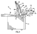
- Fig. 1 shows a platesetter 10 with a plate cassette loader 100 comprising a cassette holder 110 and a cassette inverter 105, which have been constructed according to the principles of the present invention.
- the platesetter 10 generally comprises an infeed port 16 that conveys plates to an imaging engine in the general region of 12.
- the plates are typically loaded onto an imaging drum of the image engine and exposed, typically in a raster fashion by a scanning laser. Plates are thereafter ejected through an outfeed port 18 to a finished plate location 20. Thereafter, the plates are typically transported for further processing including development.
- the plate cassette loader 100 generally comprises a cassette holder 110 and a cassette inverter 105.
- the cassette holder 110 comprises a cassette frame 112.
- a cassette 14 is inserted into this frame 112 by an operator by sliding the cassette in the rearward direction into the frame 112.
- the cassette holder 110 further comprises, in the illustrated embodiment, a plate picker system 114.
- This plate picker engages a top plate of a stack of plates held in the cassette 14, and then conveys that picked plate to the picker mouth 116.
- the cassette inverter 105 comprises two stationary inverter arms 118 and two link arms 124.
- the inverter arms 118 generally extend vertically from the frame or body of the platesetter 10 in the fashion of a cantilever.
- Each inverter arm comprises an inverter track 120, which is generally arcuate, curving upward from the body of the platesetter and slightly rearward.
- a roller 122 which is journaled to the cassette frame 112, rides in and is confined by the inverter track 120 in the inverter arm 118.
- link arm 124 One end of the link arm 124 is journaled to the inverter arm 118 near the base of the inverter arm 118, where it connects to the body of the platesetter 10. This allows the link arm 124 to pivot on the inverter arm 118. In the illustrated load position of Fig. 1, the link arm extends from the base of the inverter arm 118, generally forward. The proximal or other end of the link arm 124 is journaled to a pin 126 on the cassette frame 112.
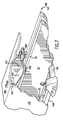
- Fig. 2 shows the plate cassette loader 100 in an intermediate position, between a load position and a feed position.
- An actuation system 200 of the cassette inverter 105 is lifting the rear or distal end of the cassette 14 and frame 112, while lifting and rotating the proximal end of the cassette 14 in the rearward direction. This action moves the picker mouth 116 in the direction of the infeed port 16.
- the path of this translation and inversion of the cassette 14 is controlled by the movement of roller 122 in the inverter track 120, which constrain the movement of the distal end of the frame 112, while the path of the proximal end of the frame and cassette is controlled by the link arm 124.
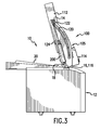
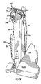
- Fig. 3 shows the plate cassette loader 100 in the feed position.
- the cassette 14 is oriented in a position that is 15 degrees from vertical. It corresponds to the typical feed position for plates into the imaging engine 12.
- the picker mouth 116 is cooperating with the infeed port 16 of the imaging engine 12. This allows individual plates to be picked-off of the stack of plates in the cassette 14 and fed through the picker mouth 116, into the infeed port 16 and to the drum of the imaging engine 12.
- Fig. 4 shows some more details of the plate cassette loader 100 and specifically the cassette holder 110 and the two inverter arms 118 of the cassette inverter 105, with the picker 114 removed. Specifically, the two arms 118 are located on either side of the cassette holder's frame 112. The inverter arms 118 are connected to the platesetter body 22 by corresponding brackets 160. The imaging engine 12 is located within the platesetter frame 22.
- Fig. 5 is a more detailed view of the interconnection between the inverter arm 118 shown in phantom, the link arm 124, and the frame 112 of the cassette holder.
- the cassette frame 112 comprises a U-shaped member 132 that wraps under and over the cassette 14.
- a lower leg 162 extends under a bottom of a tray portion 130 of the cassette 14.
- An upper leg 164 extends over a cover portion 166 of the cassette.
- a cross member 170 extends laterally across the cassette frame 112 to another U-shaped member on the other side of the frame.
- the U-shaped member 132 defines an insertion channel 168 into which the operator inserts the cassette 14 between the upper and lower legs 164, 162 of the U-shaped member 132.
- a reinforcing frame member 134 is attached to the side of the U-shaped member 132. It carries the journaled pin 126 that engages the link arm 124 to provide the pivot engagement and the roller 122 that rides in the inverter track of the inverter arm 118.
- Fig. 6 shows an underside of the cassette frame and cassette 14 with the U-shaped member 132 partially cut-away. This exposes a track 140, which is secured to the lower leg 162 of the U-shaped member 132.
- This track 140 comprises outer and inner rails 170, 172 that are riveted to the lower leg 162. Wheels 22 of the cassette 14 ride in a V-shaped trough between these outer and inner rails 170, 172 so that the cassette 14 may be smoothly inserted into the channel between the U-shaped brackets 132 on either side of the frame.
- a latching mechanism 141 which is bolted to lower leg 162.
- the latching mechanism 141 is used to retain the cassette 14 in the channel of the cassette holder.
- a pin 124 on the cassette 14, is provided that projects down from the bottom of the tray 130 of the cassette 14. Upon full insertion, it engages the latching mechanism 141 that is secured onto the lower leg 162.
- This latching mechanism 141 retains the pin 124, and thus holds the cassette 14 in the cassette holder 110 during the process of inverting the cassette 14 to the feed position.
- Fig. 7 shows a spring member 151 that is used to constrain the cassette 14 in the channel defined by the U-shaped bracket 132.
- the spring members 151 are secured to an inner side of the upper legs 164 such that they project down into the insertion channel 168.
- the spring members 151 each include a nib 150 that engages a top edge 32 of the cassette 14.
- the leaf spring portion 152 then urges the cassette 14 downward so that the wheels 22 stay within the track 140.
- the leaf spring portion is bolted to the upper leg 164 with intervening resilent blocks 154, 156. This way, the cassette 14 is securely held in the cassette holder 105 during its movement between the load position and the feed position.
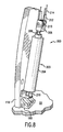
- Fig. 8 shows the detail of the actuation system 200. It comprises an air cylinder system 203, which includes an outer cylinder 204 and an inner piston 206. The cylinder's base is attached to a bracket 216 that is bolted to the inverter arm 118. A piston pulley block 208 is attached to the head of the piston 206. The piston pulley block 208 carries a pulley 210. Tackle wire 214 is further terminated 212 on the piston pulley block 208.
- Fig. 9 shows a top pulley block 220 that is attached at the top of the inverter arm 118.
- the wire tackle 214 extends from termination 212 over pulley 222 on the top block 220 to pulley 210 on the piston block 208, to pulley 224 on the top block 220.
- the tackle then runs over pulley 226, with the other end attaching to roller 122.
- the system of pulleys provides a mechanical advantage of one third (1/3).
- the piston displacement is 203mm (8 inches) thereby moving the slide joint 609mm (24 inches).
Landscapes
- Engineering & Computer Science (AREA)
- Mechanical Engineering (AREA)
- Manufacturing & Machinery (AREA)
- Sheets, Magazines, And Separation Thereof (AREA)
Applications Claiming Priority (2)
| Application Number | Priority Date | Filing Date | Title |
|---|---|---|---|
| US11748203A | 2003-04-05 | 2003-04-05 | |
| US117482 | 2003-04-05 |
Publications (2)
| Publication Number | Publication Date |
|---|---|
| EP1464485A2 true EP1464485A2 (de) | 2004-10-06 |
| EP1464485A3 EP1464485A3 (de) | 2007-02-21 |
Family
ID=32848896
Family Applications (1)
| Application Number | Title | Priority Date | Filing Date |
|---|---|---|---|
| EP03100929A Withdrawn EP1464485A3 (de) | 2003-04-05 | 2003-04-07 | Ladegerät für Druckplattenkassetten in einer Bebilderungseinrichtung |
Country Status (1)
| Country | Link |
|---|---|
| EP (1) | EP1464485A3 (de) |
Cited By (1)
| Publication number | Priority date | Publication date | Assignee | Title |
|---|---|---|---|---|
| CN114228307A (zh) * | 2021-12-13 | 2022-03-25 | 杭州科雷机电工业有限公司 | 一种五版盒的供版系统及其供版实现方法 |
Family Cites Families (5)
| Publication number | Priority date | Publication date | Assignee | Title |
|---|---|---|---|---|
| JPS61248834A (ja) * | 1985-04-24 | 1986-11-06 | Mitsubishi Heavy Ind Ltd | 枚葉印刷機における刷版交換装置 |
| DE4130359C2 (de) * | 1991-09-12 | 1997-04-17 | Heidelberger Druckmasch Ag | Vorrichtung zum Ab- und/oder Zuführen von Druckplatten einer Druckmaschine |
| US5788455A (en) * | 1996-07-31 | 1998-08-04 | Agfa Divison, Bayer Corporation | Method and apparatus for picking and transporting plates in an automated platesetter |
| DE19814661B4 (de) * | 1998-03-31 | 2004-05-13 | Heidelberger Druckmaschinen Ag | Zusatzeinrichtung für ein Druckwerk |
| JP4410344B2 (ja) * | 1999-09-17 | 2010-02-03 | 株式会社小森コーポレーション | 版保持装置 |
-
2003
- 2003-04-07 EP EP03100929A patent/EP1464485A3/de not_active Withdrawn
Cited By (1)
| Publication number | Priority date | Publication date | Assignee | Title |
|---|---|---|---|---|
| CN114228307A (zh) * | 2021-12-13 | 2022-03-25 | 杭州科雷机电工业有限公司 | 一种五版盒的供版系统及其供版实现方法 |
Also Published As
| Publication number | Publication date |
|---|---|
| EP1464485A3 (de) | 2007-02-21 |
Similar Documents
| Publication | Publication Date | Title |
|---|---|---|
| US6726433B1 (en) | Apparatus for loading and unloading a supply of plates in an automated plate handler | |
| US5992324A (en) | Method and apparatus for making lithographic printing plates in an automated computer to plate imaging system | |
| US7301550B2 (en) | CD recorder and printer | |
| US5655452A (en) | Method and apparatus for an automated plate handler with slip sheet removal mechanism | |
| US5809360A (en) | Cassette for storing and accessing plates within an automated plate handler | |
| US4889233A (en) | Cassette for stimulable phosphor sheet | |
| US5788455A (en) | Method and apparatus for picking and transporting plates in an automated platesetter | |
| US7004717B2 (en) | Plate cassette loader for platesetter | |
| EP0767574A3 (de) | Datenverarbeitungsgerät mit beweglichem Behältertisch | |
| EP1464485A2 (de) | Ladegerät für Druckplattenkassetten in einer Bebilderungseinrichtung | |
| EP1630597A3 (de) | Bildabtastvorrichtung | |
| US4986527A (en) | Method and mechanism for feeding and positioning a sheet | |
| US5087025A (en) | Sheet delivery mechanism having a suction feeder including a movable roller pair | |
| CN1572687A (zh) | 送纸装置、图像读取设备和成像设备 | |
| JPS63267619A (ja) | ドキュメント入出力のための複数モードで作動する装置 | |
| US4444493A (en) | Platen cover for a copier having a document retaining pocket | |
| JP2005070781A (ja) | 版面管理システムの版面インバータおよび版面管理方法 | |
| JP4129117B2 (ja) | シート体用容器の排出機構 | |
| JP4015777B2 (ja) | 容器の誤挿入防止構造および容器処理装置 | |
| JPH07444Y2 (ja) | ドラム型画像走査記録装置の感材着脱装置 | |
| JPS63101227A (ja) | シ−ト体搬送機構 | |
| JPS6011858Y2 (ja) | プリンタにおける給紙装置 | |
| JPS6360859A (ja) | シ−ト体搬送機構 | |
| US20050040586A1 (en) | Sheet body feeding guide structure | |
| JPH1080996A (ja) | 昇降及びテーブル支持機構を備えた自動版ハンドラーのための方法及び装置 |
Legal Events
| Date | Code | Title | Description |
|---|---|---|---|
| PUAI | Public reference made under article 153(3) epc to a published international application that has entered the european phase |
Free format text: ORIGINAL CODE: 0009012 |
|
| AK | Designated contracting states |
Kind code of ref document: A2 Designated state(s): AT BE BG CH CY CZ DE DK EE ES FI FR GB GR HU IE IT LI LU MC NL PT RO SE SI SK TR |
|
| AX | Request for extension of the european patent |
Extension state: AL LT LV MK |
|
| PUAL | Search report despatched |
Free format text: ORIGINAL CODE: 0009013 |
|
| AK | Designated contracting states |
Kind code of ref document: A3 Designated state(s): AT BE BG CH CY CZ DE DK EE ES FI FR GB GR HU IE IT LI LU MC NL PT RO SE SI SK TR |
|
| AX | Request for extension of the european patent |
Extension state: AL LT LV MK |
|
| RIC1 | Information provided on ipc code assigned before grant |
Ipc: B41C 1/00 20060101ALI20070112BHEP Ipc: B41C 1/10 20060101ALI20070112BHEP Ipc: B41F 35/00 20060101ALI20070112BHEP Ipc: B41F 13/24 20060101ALI20070112BHEP Ipc: B41F 13/00 20060101ALI20070112BHEP Ipc: B41F 27/12 20060101AFI20070112BHEP |
|
| 17P | Request for examination filed |
Effective date: 20070821 |
|
| AKX | Designation fees paid |
Designated state(s): DE FR GB |
|
| 17Q | First examination report despatched |
Effective date: 20071022 |
|
| GRAP | Despatch of communication of intention to grant a patent |
Free format text: ORIGINAL CODE: EPIDOSNIGR1 |
|
| GRAS | Grant fee paid |
Free format text: ORIGINAL CODE: EPIDOSNIGR3 |
|
| STAA | Information on the status of an ep patent application or granted ep patent |
Free format text: STATUS: THE APPLICATION IS DEEMED TO BE WITHDRAWN |
|
| 18D | Application deemed to be withdrawn |
Effective date: 20091103 |