EP1464459B1 - Verformbare, schwimmend gelagerte schneidvorrichtung - Google Patents
Verformbare, schwimmend gelagerte schneidvorrichtung Download PDFInfo
- Publication number
- EP1464459B1 EP1464459B1 EP01274994A EP01274994A EP1464459B1 EP 1464459 B1 EP1464459 B1 EP 1464459B1 EP 01274994 A EP01274994 A EP 01274994A EP 01274994 A EP01274994 A EP 01274994A EP 1464459 B1 EP1464459 B1 EP 1464459B1
- Authority
- EP
- European Patent Office
- Prior art keywords
- striking plate
- cutting
- deformable
- blade
- cutting apparatus
- Prior art date
- Legal status (The legal status is an assumption and is not a legal conclusion. Google has not performed a legal analysis and makes no representation as to the accuracy of the status listed.)
- Expired - Lifetime
Links
- 238000005520 cutting process Methods 0.000 title claims abstract description 66
- 238000007667 floating Methods 0.000 title claims description 11
- 229920001971 elastomer Polymers 0.000 claims abstract description 12
- 239000000806 elastomer Substances 0.000 claims abstract description 12
- 229910000831 Steel Inorganic materials 0.000 claims abstract description 6
- 239000010959 steel Substances 0.000 claims abstract description 6
- 238000009966 trimming Methods 0.000 claims abstract description 3
- 238000004519 manufacturing process Methods 0.000 claims description 3
- 238000003825 pressing Methods 0.000 claims description 3
- 229910000851 Alloy steel Inorganic materials 0.000 claims description 2
- 239000002184 metal Substances 0.000 claims description 2
- 229910052751 metal Inorganic materials 0.000 claims description 2
- 238000005304 joining Methods 0.000 claims 1
- 230000000284 resting effect Effects 0.000 claims 1
- 241000761557 Lamina Species 0.000 abstract 1
- 239000000463 material Substances 0.000 description 5
- 239000011152 fibreglass Substances 0.000 description 3
- 238000010008 shearing Methods 0.000 description 3
- 229920005830 Polyurethane Foam Polymers 0.000 description 2
- 239000000853 adhesive Substances 0.000 description 2
- 230000001070 adhesive effect Effects 0.000 description 2
- 230000008878 coupling Effects 0.000 description 2
- 238000010168 coupling process Methods 0.000 description 2
- 238000005859 coupling reaction Methods 0.000 description 2
- 239000004744 fabric Substances 0.000 description 2
- 238000012423 maintenance Methods 0.000 description 2
- 239000000123 paper Substances 0.000 description 2
- 239000011496 polyurethane foam Substances 0.000 description 2
- 229920001875 Ebonite Polymers 0.000 description 1
- 230000002159 abnormal effect Effects 0.000 description 1
- 230000005540 biological transmission Effects 0.000 description 1
- 230000002950 deficient Effects 0.000 description 1
- 230000005489 elastic deformation Effects 0.000 description 1
- 238000005516 engineering process Methods 0.000 description 1
- 239000011810 insulating material Substances 0.000 description 1
- 150000002739 metals Chemical class 0.000 description 1
- 238000000034 method Methods 0.000 description 1
- 239000000203 mixture Substances 0.000 description 1
- 238000000465 moulding Methods 0.000 description 1
- 230000000149 penetrating effect Effects 0.000 description 1
- 239000004033 plastic Substances 0.000 description 1
- 229920003023 plastic Polymers 0.000 description 1
- 239000002985 plastic film Substances 0.000 description 1
- 229920006255 plastic film Polymers 0.000 description 1
- 230000002028 premature Effects 0.000 description 1
Images

Classifications
-
- B—PERFORMING OPERATIONS; TRANSPORTING
- B26—HAND CUTTING TOOLS; CUTTING; SEVERING
- B26D—CUTTING; DETAILS COMMON TO MACHINES FOR PERFORATING, PUNCHING, CUTTING-OUT, STAMPING-OUT OR SEVERING
- B26D7/00—Details of apparatus for cutting, cutting-out, stamping-out, punching, perforating, or severing by means other than cutting
- B26D7/20—Cutting beds
-
- B—PERFORMING OPERATIONS; TRANSPORTING
- B26—HAND CUTTING TOOLS; CUTTING; SEVERING
- B26F—PERFORATING; PUNCHING; CUTTING-OUT; STAMPING-OUT; SEVERING BY MEANS OTHER THAN CUTTING
- B26F1/00—Perforating; Punching; Cutting-out; Stamping-out; Apparatus therefor
- B26F1/38—Cutting-out; Stamping-out
- B26F1/40—Cutting-out; Stamping-out using a press, e.g. of the ram type
-
- B—PERFORMING OPERATIONS; TRANSPORTING
- B29—WORKING OF PLASTICS; WORKING OF SUBSTANCES IN A PLASTIC STATE IN GENERAL
- B29C—SHAPING OR JOINING OF PLASTICS; SHAPING OF MATERIAL IN A PLASTIC STATE, NOT OTHERWISE PROVIDED FOR; AFTER-TREATMENT OF THE SHAPED PRODUCTS, e.g. REPAIRING
- B29C51/00—Shaping by thermoforming, i.e. shaping sheets or sheet like preforms after heating, e.g. shaping sheets in matched moulds or by deep-drawing; Apparatus therefor
- B29C51/26—Component parts, details or accessories; Auxiliary operations
- B29C51/30—Moulds
- B29C51/32—Moulds having cutting means
-
- B—PERFORMING OPERATIONS; TRANSPORTING
- B26—HAND CUTTING TOOLS; CUTTING; SEVERING
- B26F—PERFORATING; PUNCHING; CUTTING-OUT; STAMPING-OUT; SEVERING BY MEANS OTHER THAN CUTTING
- B26F2210/00—Perforating, punching, cutting-out, stamping-out, severing by means other than cutting of specific products
- B26F2210/06—Trimming plastic mouldings
-
- B—PERFORMING OPERATIONS; TRANSPORTING
- B29—WORKING OF PLASTICS; WORKING OF SUBSTANCES IN A PLASTIC STATE IN GENERAL
- B29C—SHAPING OR JOINING OF PLASTICS; SHAPING OF MATERIAL IN A PLASTIC STATE, NOT OTHERWISE PROVIDED FOR; AFTER-TREATMENT OF THE SHAPED PRODUCTS, e.g. REPAIRING
- B29C2793/00—Shaping techniques involving a cutting or machining operation
-
- B—PERFORMING OPERATIONS; TRANSPORTING
- B29—WORKING OF PLASTICS; WORKING OF SUBSTANCES IN A PLASTIC STATE IN GENERAL
- B29C—SHAPING OR JOINING OF PLASTICS; SHAPING OF MATERIAL IN A PLASTIC STATE, NOT OTHERWISE PROVIDED FOR; AFTER-TREATMENT OF THE SHAPED PRODUCTS, e.g. REPAIRING
- B29C51/00—Shaping by thermoforming, i.e. shaping sheets or sheet like preforms after heating, e.g. shaping sheets in matched moulds or by deep-drawing; Apparatus therefor
- B29C51/08—Deep drawing or matched-mould forming, i.e. using mechanical means only
- B29C51/082—Deep drawing or matched-mould forming, i.e. using mechanical means only by shaping between complementary mould parts
-
- B—PERFORMING OPERATIONS; TRANSPORTING
- B29—WORKING OF PLASTICS; WORKING OF SUBSTANCES IN A PLASTIC STATE IN GENERAL
- B29L—INDEXING SCHEME ASSOCIATED WITH SUBCLASS B29C, RELATING TO PARTICULAR ARTICLES
- B29L2031/00—Other particular articles
- B29L2031/30—Vehicles, e.g. ships or aircraft, or body parts thereof
- B29L2031/3005—Body finishings
- B29L2031/3011—Roof linings
Definitions
- the present invention relates to a cutting apparatus which will be termed deformable floating, for application in any pressure cutting process in which the linear cutting pressure is less than 10 7 N/m and the tolerance in the cutting direction is greater than 0.2 mm, which signifies that with this apparatus it is possible to cut, among other things, sandwich type panels of different compositions.
- these can contain layers of fabric, polyurethane foams, fibreglass, paper, etc., with different thickness.
- a typical example of a sandwich panel employed in the manufacturing technologies of roof linings is that constituted by the following layers: paper, fibreglass, adhesive, polyurethane foam, adhesive, fibreglass, plastic film and fabric.
- the cutting apparatus is specially suitable for use in the automobile industry, specifically in the production of motor vehicle roof linings, wherein simultaneously with the moulding of the roof the trimming of the surplus material thereof takes place, in the same machine and in the same operation.
- the object of the invention is to be able to absorb the possible misalignments, wear, or imperfections of moulds and working machines, that is to absorb possible deviations in position of moulds, blades and presses within certain limits. This is because in any machine of the aforementioned type there is no "zero" tolerance, and however to achieve an adequate cut a perfect alignment of the elements which intervene is required, for which reason it is necessary that at least one of them be capable of adjustment until adapting to the geometry and position of the other.
- Pressure cutting is characterised in that the piece is held between blade and striking plate until the pressure applied by both reaches the value sufficient to cut the piece.
- blade and striking plate are gradually brought together until in the final instant in which the cutting becomes effective, direct contact takes place between the two.
- the cutting apparatus of the invention is applicable to pressure cutting systems, which in many cases of cutting and conforming linings is preferred over the other two systems because of its greater simplicity in implementation and reliability.
- pressure cutting to be effective, requires a very precise alignment between striking plate and blade, which limits its use and needs frequent and specialized operations of maintenance and alignment.
- the cutting apparatus of the invention comprises the features of claim 1. It is applicable to pressure cutting systems.
- the cutting apparatus which the invention discloses centres its characteristics on the fact that one of the two basic elements that participates therein, be it the striking plate, admits certain relative movements of alignment apart from the actual cutting movement. This implies a matching of the moving part to the fixed part, which permits perfect coupling between the two at the end of each cutting cycle, as well as self-alignment with time during the useful life of the cutting tool, and between different machines.
- the striking plate is flexible and is mounted on an elastic support, in such a way that the pressure of the blade deforms the striking plate to adapt it to the profile of the blade, while the elastic support must have a sufficiently high spring constant to absorb and distribute the cutting force evenly over all points of the edge.
- the steel striking plate needs to have sufficient thickness to prevent it from being damaged by the blade, and at the same time also sufficient to be able to adapt by elastic deformation to the latter through its own deformation.
- the elastic support located under the striking plate has to be sufficiently rigid to permit a similar thrust on all points of its surface and at the same time prevent the striking plate from being introduced inside it.
- the striking plate will be made of alloy steel for wear-resistant tools of the group F-500 (according to Spanish IHA standards), with surface hardness of between 40 and 60 HRc.
- the striking plate can be formed by a single sheet, its thickness being between 0.5 and 5 millimetres, by two or three superimposed sheets of thickness between 0.5 and 5 millimetres each one.
- the striking plate runs the whole cutting line and is formed by consecutive segments of at least 200 mm each, and whose width will lie between 4 and 50 mm.
- the elastic support or elastomer will be of a thickness between 2 and 8 millimetres and have a Shore A hardness of between 75 and 95.
- the join between the striking plate and the elastomer or elastic support is free by simply support, the movement of these being guided by the channel in which they are housed and restricted in the direction parallel to that of cutting by a fastening which maintains both elements within said channel by way of a retainer.
- the steel striking plate (3) rests on an elastic support (4), preferably an elastomer which deforms at the same time as the striking plate (3), absorbing the deformation of the latter, as one observes in figure 2.
- the striking plate (3) basically laminar, needs to have sufficient thickness to prevent it from being damaged by the blade (1), allowing nevertheless a perfect coupling with the latter when both are subjected to the cutting force.
- the thickness of the striking plate is small the latter will be cut by the blade, whilst if the thickness of the striking plate is large the desired deformation will not be achieved and therefore gaps will be produced between blade and striking plate, resulting in a faulty cut.
- the elastomer (4) has to be sufficiently rigid to allow a similar thrust on all points thereof and at the same time prevent the striking plate from penetrating inside it.
- a soft elastomer would cause the striking plate to be driven inside it causing the shearing thereof, whilst a very hard elastomer, even if achieving the deformation to match the blade and striking plate, would have differences in pressure which would also cause the cut to be deficient in some points and increase the risk of wear or premature damage in the blade.
- the striking plate has to have its movement restricted inside its housing to prevent it being pulled by the blade on withdrawing the latter.
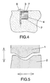
- the striking plate (3) can be of the same width as the channel (6), so that said striking plate (3) with the elastomer (4) and the lagging (7) is secured to the mould by means of a fastening screw (9) located laterally with respect to the striking plate (3), the same as what occurred with the press-fitted wedge (8) of the example of the previous figure.
- the purpose of the lagging (7) is to prevent transmission of the heat from the mould to the striking plate, when the working temperatures are sufficiently high as to degrade the material of the elastomer.
Landscapes
- Engineering & Computer Science (AREA)
- Mechanical Engineering (AREA)
- Life Sciences & Earth Sciences (AREA)
- Forests & Forestry (AREA)
- Perforating, Stamping-Out Or Severing By Means Other Than Cutting (AREA)
- Shearing Machines (AREA)
- Control Of Cutting Processes (AREA)
- Finish Polishing, Edge Sharpening, And Grinding By Specific Grinding Devices (AREA)
- Surgical Instruments (AREA)
- Nonmetal Cutting Devices (AREA)
Claims (7)
- Verformbare, schwebende Schneidvorrichtung, die besonders sowohl bei Maschinen, die nur das Schneiden durchführen, als auch bei denen, die gleichzeitig das Pressen, Anpassen und Beschneiden eines Schichtwerkstoffteils oder dergleichen ausführen, eingesetzt wird, so beispielsweise bei der Herstellung von Dachhimmeln für Fahrzeuge, und die dazu dient, mögliche Positionsabweichungen sowohl bei den Schneidelementen als auch den Formen und den Bearbeitungsmaschinen selbst auszugleichen, wobei sie dadurch gekennzeichnet ist, dass die Schlagplatte (3) beweglich und elastisch verformbar ist und vorzugsweise aus flexiblem Stahl besteht, um sich an das Schneidprofil (2) der Schneide (1) anzupassen, wobei die Schlagplatte (3) so angebracht ist, dass sie einfach oder mit einer dazwischen befindlichen Isolierschicht (7) auf einem elastischen Träger (4) aufliegt, der den Schneiddruck und die Verformung der Schlagplatte absorbiert, und die folgenden Parameter gegeben sind:die Schlagplatte (3) besteht aus verschleißbeständigem Legierungsstahl der Gruppe F-500 nach IHA-Standards mit einer Oberflächenhärte zwischen 40 und 60 HRc;die Dicke der Schlagplatte (3) beträgt zwischen 0,5 und 5 mm, ihre Länge deckt die gesamte Schnittlinie ab, sie ist in aufeinander folgenden Segmenten von wenigstens jeweils 200 mm ausgebildet und ihre Breite beträgt zwischen 4 und 100 mm,der elastische Träger (4) hat eine Dicke zwischen 2 und 8 mm, und er hat eine Shore-A-Härte zwischen 75 und 95.
- Verformbare schwebende Schneidvorrichtung nach Anspruch 1, dadurch gekennzeichnet, dass die Schlagplatte (3) als ein Metallstreifen, vorzugsweise aus Stahl, ausgeführt ist, der elastisch verformbar ist und auf einem Träger (4) aufliegt, der seinerseits elastisch ist und vorzugsweise aus einem Elastomer besteht und eine Federkonstante hat, die ausreicht, um dem Schneiddruck zu widerstehen und die dauerhafte Verformung der Schlagplatte zu vermeiden.
- Verformbare schwebende Schneidvorrichtung nach Anspruch 1 oder 2, dadurch gekennzeichnet, dass optional die Schlagplatte (3) eine mehrschichtige Struktur hat und insbesondere mit einer Dicke zwischen 0,5 und 5 mm in jeder Schicht.
- Verformbare schwebende Schneidvorrichtung nach einem der vorangehenden Ansprüche, dadurch gekennzeichnet, dass die Schlagplatte (3) und der elastische Träger (4) im freien Segment des letzteren miteinander verbunden sind, ohne dass zusätzliche Einrichtungen zum Verbinden der beiden miteinander erforderlich sind.
- Verformbare schwebende Schneidvorrichtung nach einem der vorangehenden Ansprüche, dadurch gekennzeichnet, dass sie auch eine isolierende Schicht mit einer Dicke zwischen 0,5 und 2,5 mm und einer Beständigkeit gegenüber Temperaturen bis zu wenigstens 200°C enthalten kann.
- Verformbare schwebende Schneidvorrichtung nach den vorangehenden Ansprüchen, dadurch gekennzeichnet, dass die Schlagplatte und der elastische Träger (4) in einem Kanal (6) der Form (5) im Zusammenwirken mit einem Befestigungssystem angeordnet sind, das beide Elemente mittels einer Halteeinrichtung in dem Kanal hält, wobei die Bewegung derselben durch den Kanal geführt wird, der sie aufnimmt, und in der Richtung parallel zu der des Schneidens eingeschränkt ist.
- Verformbare schwebende Schneidvorrichtung nach einem der vorangehenden Ansprüche, dadurch gekennzeichnet, dass das System zum Befestigen der Schlagplatte (3) in dem Kanal (6) der Form (5) im Zusammenwirken mit einem Spannkeil (8) oder im Zusammenwirken mit einer Schraube (9) umgesetzt wird, die in jedem Fall auf wenigstens eine der Seiten der Schlagplatte (3) wirken.
Applications Claiming Priority (1)
| Application Number | Priority Date | Filing Date | Title |
|---|---|---|---|
| PCT/ES2001/000492 WO2003051591A1 (es) | 2001-12-18 | 2001-12-18 | Dispositivo de corte flotante deformable |
Publications (2)
| Publication Number | Publication Date |
|---|---|
| EP1464459A1 EP1464459A1 (de) | 2004-10-06 |
| EP1464459B1 true EP1464459B1 (de) | 2007-02-07 |
Family
ID=8244412
Family Applications (1)
| Application Number | Title | Priority Date | Filing Date |
|---|---|---|---|
| EP01274994A Expired - Lifetime EP1464459B1 (de) | 2001-12-18 | 2001-12-18 | Verformbare, schwimmend gelagerte schneidvorrichtung |
Country Status (8)
| Country | Link |
|---|---|
| EP (1) | EP1464459B1 (de) |
| CN (1) | CN1325234C (de) |
| AT (1) | ATE353273T1 (de) |
| AU (1) | AU2002216124A1 (de) |
| DE (1) | DE60126518T2 (de) |
| ES (1) | ES2282203T3 (de) |
| MX (1) | MXPA04005846A (de) |
| WO (1) | WO2003051591A1 (de) |
Families Citing this family (4)
| Publication number | Priority date | Publication date | Assignee | Title |
|---|---|---|---|---|
| US8057206B1 (en) * | 2007-09-13 | 2011-11-15 | Hrl Laboratories, Llc | Reconfigurable tooling using variable stiffness material |
| DE102010031408B4 (de) * | 2010-07-15 | 2017-12-21 | Bayerische Motoren Werke Aktiengesellschaft | Werkzeug zum Beschneiden von Fasermaterialien |
| US11528916B2 (en) | 2019-02-12 | 2022-12-20 | Marel A/S | Cutting apparatus with element for receiving and abutting cutting blade |
| CN113245608B (zh) * | 2021-05-06 | 2022-09-27 | 福建省阳光三源铝业有限公司 | 一种防挤压变形的铝型材切削加工装置 |
Family Cites Families (4)
| Publication number | Priority date | Publication date | Assignee | Title |
|---|---|---|---|---|
| US2120926A (en) * | 1937-01-26 | 1938-06-14 | Wilmington Fibre Specialty Com | Cutting stick |
| FR840211A (fr) * | 1937-07-05 | 1939-04-21 | Barre de coupe, notamment pour machines à couper le papier | |
| AT247131B (de) * | 1962-11-30 | 1966-05-25 | Josef Grafl | Schneidleistenanordnung für eine Papierschneidmaschine |
| US3269234A (en) * | 1964-07-17 | 1966-08-30 | Compo Shoe Machinery Corp | Automatic cutting machine and method for compensation of minor structural misalignment |
-
2001
- 2001-12-18 CN CNB018239315A patent/CN1325234C/zh not_active Expired - Fee Related
- 2001-12-18 ES ES01274994T patent/ES2282203T3/es not_active Expired - Lifetime
- 2001-12-18 MX MXPA04005846A patent/MXPA04005846A/es active IP Right Grant
- 2001-12-18 AU AU2002216124A patent/AU2002216124A1/en not_active Abandoned
- 2001-12-18 AT AT01274994T patent/ATE353273T1/de not_active IP Right Cessation
- 2001-12-18 WO PCT/ES2001/000492 patent/WO2003051591A1/es not_active Ceased
- 2001-12-18 DE DE60126518T patent/DE60126518T2/de not_active Expired - Fee Related
- 2001-12-18 EP EP01274994A patent/EP1464459B1/de not_active Expired - Lifetime
Also Published As
| Publication number | Publication date |
|---|---|
| CN1325234C (zh) | 2007-07-11 |
| MXPA04005846A (es) | 2005-05-17 |
| CN1582219A (zh) | 2005-02-16 |
| EP1464459A1 (de) | 2004-10-06 |
| AU2002216124A1 (en) | 2003-06-30 |
| WO2003051591A1 (es) | 2003-06-26 |
| ES2282203T3 (es) | 2007-10-16 |
| ATE353273T1 (de) | 2007-02-15 |
| DE60126518D1 (de) | 2007-03-22 |
| DE60126518T2 (de) | 2007-11-08 |
Similar Documents
| Publication | Publication Date | Title |
|---|---|---|
| EP1464458B1 (de) | Starre, schwimmend gelagerte schneidvorrichtung | |
| EP2479010A1 (de) | Schneidegerät | |
| KR101083483B1 (ko) | 웨지 드라이브 | |
| KR101897794B1 (ko) | 공작물 위치고정 클램핑장치 | |
| EP1464459B1 (de) | Verformbare, schwimmend gelagerte schneidvorrichtung | |
| US8863566B2 (en) | Tool fastening device for a wedge drive | |
| CN201507511U (zh) | 一种弹性楔键 | |
| US4207048A (en) | Power presses and components for such presses | |
| EP0472097B1 (de) | Rotierende Stanzvorrichtung | |
| KR200209848Y1 (ko) | 펀칭다이 결합구조 | |
| KR100722877B1 (ko) | 파인 블랭킹 프레스의 2매타발 방지장치 | |
| US5067339A (en) | Cutting and forming tool for complicated flat structures | |
| JP2007268650A (ja) | ダイカットロール | |
| CN213495905U (zh) | 用于h型导轨的斜切端头模具结构 | |
| CN219541857U (zh) | 碎断剪 | |
| CN218694309U (zh) | 一种钣金件生产用剪板机 | |
| CN207857943U (zh) | 剪板机手动送料限位组件 | |
| KR100412679B1 (ko) | 크롭 블랭킹 다이 | |
| KR101904460B1 (ko) | 와이퍼용 구동샤프트 및 그 가공장치 | |
| CN211371232U (zh) | 一种减速机 | |
| EP1529593A1 (de) | Verfahren zur Herstellung grosser Bleche mit Laserschweissen in Kombination mit Druckrollen und Spanntisch mit Mittel zum Bewegen zweier Spanntischteile | |
| CN209902026U (zh) | 料片剪切装置 | |
| EP3906125B1 (de) | Biegemaschine | |
| CN217193938U (zh) | 一种机械加工用固定夹具 | |
| CN215395572U (zh) | 一种裁切装置及滚刀机构 |
Legal Events
| Date | Code | Title | Description |
|---|---|---|---|
| PUAI | Public reference made under article 153(3) epc to a published international application that has entered the european phase |
Free format text: ORIGINAL CODE: 0009012 |
|
| 17P | Request for examination filed |
Effective date: 20040628 |
|
| AK | Designated contracting states |
Kind code of ref document: A1 Designated state(s): AT BE CH CY DE DK ES FI FR GB GR IE IT LI LU MC NL PT SE TR |
|
| AX | Request for extension of the european patent |
Extension state: AL LT LV MK RO SI |
|
| 17Q | First examination report despatched |
Effective date: 20050704 |
|
| GRAP | Despatch of communication of intention to grant a patent |
Free format text: ORIGINAL CODE: EPIDOSNIGR1 |
|
| GRAS | Grant fee paid |
Free format text: ORIGINAL CODE: EPIDOSNIGR3 |
|
| GRAA | (expected) grant |
Free format text: ORIGINAL CODE: 0009210 |
|
| AK | Designated contracting states |
Kind code of ref document: B1 Designated state(s): AT BE CH CY DE DK ES FI FR GB GR IE IT LI LU MC NL PT SE TR |
|
| PG25 | Lapsed in a contracting state [announced via postgrant information from national office to epo] |
Ref country code: DK Free format text: LAPSE BECAUSE OF FAILURE TO SUBMIT A TRANSLATION OF THE DESCRIPTION OR TO PAY THE FEE WITHIN THE PRESCRIBED TIME-LIMIT Effective date: 20070207 Ref country code: FI Free format text: LAPSE BECAUSE OF FAILURE TO SUBMIT A TRANSLATION OF THE DESCRIPTION OR TO PAY THE FEE WITHIN THE PRESCRIBED TIME-LIMIT Effective date: 20070207 Ref country code: LI Free format text: LAPSE BECAUSE OF FAILURE TO SUBMIT A TRANSLATION OF THE DESCRIPTION OR TO PAY THE FEE WITHIN THE PRESCRIBED TIME-LIMIT Effective date: 20070207 Ref country code: NL Free format text: LAPSE BECAUSE OF FAILURE TO SUBMIT A TRANSLATION OF THE DESCRIPTION OR TO PAY THE FEE WITHIN THE PRESCRIBED TIME-LIMIT Effective date: 20070207 Ref country code: BE Free format text: LAPSE BECAUSE OF FAILURE TO SUBMIT A TRANSLATION OF THE DESCRIPTION OR TO PAY THE FEE WITHIN THE PRESCRIBED TIME-LIMIT Effective date: 20070207 Ref country code: CH Free format text: LAPSE BECAUSE OF FAILURE TO SUBMIT A TRANSLATION OF THE DESCRIPTION OR TO PAY THE FEE WITHIN THE PRESCRIBED TIME-LIMIT Effective date: 20070207 Ref country code: AT Free format text: LAPSE BECAUSE OF FAILURE TO SUBMIT A TRANSLATION OF THE DESCRIPTION OR TO PAY THE FEE WITHIN THE PRESCRIBED TIME-LIMIT Effective date: 20070207 |
|
| REG | Reference to a national code |
Ref country code: GB Ref legal event code: FG4D |
|
| REG | Reference to a national code |
Ref country code: CH Ref legal event code: EP |
|
| REG | Reference to a national code |
Ref country code: IE Ref legal event code: FG4D |
|
| REF | Corresponds to: |
Ref document number: 60126518 Country of ref document: DE Date of ref document: 20070322 Kind code of ref document: P |
|
| PG25 | Lapsed in a contracting state [announced via postgrant information from national office to epo] |
Ref country code: SE Free format text: LAPSE BECAUSE OF FAILURE TO SUBMIT A TRANSLATION OF THE DESCRIPTION OR TO PAY THE FEE WITHIN THE PRESCRIBED TIME-LIMIT Effective date: 20070507 |
|
| PG25 | Lapsed in a contracting state [announced via postgrant information from national office to epo] |
Ref country code: PT Free format text: LAPSE BECAUSE OF FAILURE TO SUBMIT A TRANSLATION OF THE DESCRIPTION OR TO PAY THE FEE WITHIN THE PRESCRIBED TIME-LIMIT Effective date: 20070709 |
|
| NLV1 | Nl: lapsed or annulled due to failure to fulfill the requirements of art. 29p and 29m of the patents act | ||
| REG | Reference to a national code |
Ref country code: CH Ref legal event code: PL |
|
| ET | Fr: translation filed | ||
| REG | Reference to a national code |
Ref country code: ES Ref legal event code: FG2A Ref document number: 2282203 Country of ref document: ES Kind code of ref document: T3 |
|
| PLBE | No opposition filed within time limit |
Free format text: ORIGINAL CODE: 0009261 |
|
| STAA | Information on the status of an ep patent application or granted ep patent |
Free format text: STATUS: NO OPPOSITION FILED WITHIN TIME LIMIT |
|
| 26N | No opposition filed |
Effective date: 20071108 |
|
| PG25 | Lapsed in a contracting state [announced via postgrant information from national office to epo] |
Ref country code: IT Free format text: LAPSE BECAUSE OF FAILURE TO SUBMIT A TRANSLATION OF THE DESCRIPTION OR TO PAY THE FEE WITHIN THE PRESCRIBED TIME-LIMIT Effective date: 20070207 Ref country code: GR Free format text: LAPSE BECAUSE OF FAILURE TO SUBMIT A TRANSLATION OF THE DESCRIPTION OR TO PAY THE FEE WITHIN THE PRESCRIBED TIME-LIMIT Effective date: 20070508 |
|
| PGFP | Annual fee paid to national office [announced via postgrant information from national office to epo] |
Ref country code: GB Payment date: 20071212 Year of fee payment: 7 |
|
| PG25 | Lapsed in a contracting state [announced via postgrant information from national office to epo] |
Ref country code: MC Free format text: LAPSE BECAUSE OF NON-PAYMENT OF DUE FEES Effective date: 20071231 |
|
| PG25 | Lapsed in a contracting state [announced via postgrant information from national office to epo] |
Ref country code: IE Free format text: LAPSE BECAUSE OF NON-PAYMENT OF DUE FEES Effective date: 20071218 |
|
| PGFP | Annual fee paid to national office [announced via postgrant information from national office to epo] |
Ref country code: DE Payment date: 20090129 Year of fee payment: 8 |
|
| PG25 | Lapsed in a contracting state [announced via postgrant information from national office to epo] |
Ref country code: CY Free format text: LAPSE BECAUSE OF FAILURE TO SUBMIT A TRANSLATION OF THE DESCRIPTION OR TO PAY THE FEE WITHIN THE PRESCRIBED TIME-LIMIT Effective date: 20070207 |
|
| GBPC | Gb: european patent ceased through non-payment of renewal fee |
Effective date: 20081218 |
|
| PG25 | Lapsed in a contracting state [announced via postgrant information from national office to epo] |
Ref country code: LU Free format text: LAPSE BECAUSE OF NON-PAYMENT OF DUE FEES Effective date: 20071218 |
|
| PG25 | Lapsed in a contracting state [announced via postgrant information from national office to epo] |
Ref country code: TR Free format text: LAPSE BECAUSE OF FAILURE TO SUBMIT A TRANSLATION OF THE DESCRIPTION OR TO PAY THE FEE WITHIN THE PRESCRIBED TIME-LIMIT Effective date: 20070207 |
|
| PGFP | Annual fee paid to national office [announced via postgrant information from national office to epo] |
Ref country code: FR Payment date: 20081224 Year of fee payment: 8 |
|
| PG25 | Lapsed in a contracting state [announced via postgrant information from national office to epo] |
Ref country code: GB Free format text: LAPSE BECAUSE OF NON-PAYMENT OF DUE FEES Effective date: 20081218 |
|
| REG | Reference to a national code |
Ref country code: FR Ref legal event code: ST Effective date: 20100831 |
|
| PG25 | Lapsed in a contracting state [announced via postgrant information from national office to epo] |
Ref country code: FR Free format text: LAPSE BECAUSE OF NON-PAYMENT OF DUE FEES Effective date: 20091231 |
|
| PG25 | Lapsed in a contracting state [announced via postgrant information from national office to epo] |
Ref country code: DE Free format text: LAPSE BECAUSE OF NON-PAYMENT OF DUE FEES Effective date: 20100701 |
|
| PGFP | Annual fee paid to national office [announced via postgrant information from national office to epo] |
Ref country code: ES Payment date: 20151207 Year of fee payment: 15 |
|
| PG25 | Lapsed in a contracting state [announced via postgrant information from national office to epo] |
Ref country code: ES Free format text: LAPSE BECAUSE OF NON-PAYMENT OF DUE FEES Effective date: 20161219 |
|
| REG | Reference to a national code |
Ref country code: ES Ref legal event code: FD2A Effective date: 20181116 |