EP1463959B1 - Method and apparatus for determining location of objects based on range reading from mulitiple sensors - Google Patents
Method and apparatus for determining location of objects based on range reading from mulitiple sensors Download PDFInfo
- Publication number
- EP1463959B1 EP1463959B1 EP02806462A EP02806462A EP1463959B1 EP 1463959 B1 EP1463959 B1 EP 1463959B1 EP 02806462 A EP02806462 A EP 02806462A EP 02806462 A EP02806462 A EP 02806462A EP 1463959 B1 EP1463959 B1 EP 1463959B1
- Authority
- EP
- European Patent Office
- Prior art keywords
- sensors
- range
- range measurements
- potential
- objects
- Prior art date
- Legal status (The legal status is an assumption and is not a legal conclusion. Google has not performed a legal analysis and makes no representation as to the accuracy of the status listed.)
- Expired - Fee Related
Links
Images


Classifications
-
- G—PHYSICS
- G01—MEASURING; TESTING
- G01S—RADIO DIRECTION-FINDING; RADIO NAVIGATION; DETERMINING DISTANCE OR VELOCITY BY USE OF RADIO WAVES; LOCATING OR PRESENCE-DETECTING BY USE OF THE REFLECTION OR RERADIATION OF RADIO WAVES; ANALOGOUS ARRANGEMENTS USING OTHER WAVES
- G01S13/00—Systems using the reflection or reradiation of radio waves, e.g. radar systems; Analogous systems using reflection or reradiation of waves whose nature or wavelength is irrelevant or unspecified
- G01S13/87—Combinations of radar systems, e.g. primary radar and secondary radar
- G01S13/878—Combination of several spaced transmitters or receivers of known location for determining the position of a transponder or a reflector
-
- G—PHYSICS
- G01—MEASURING; TESTING
- G01S—RADIO DIRECTION-FINDING; RADIO NAVIGATION; DETERMINING DISTANCE OR VELOCITY BY USE OF RADIO WAVES; LOCATING OR PRESENCE-DETECTING BY USE OF THE REFLECTION OR RERADIATION OF RADIO WAVES; ANALOGOUS ARRANGEMENTS USING OTHER WAVES
- G01S13/00—Systems using the reflection or reradiation of radio waves, e.g. radar systems; Analogous systems using reflection or reradiation of waves whose nature or wavelength is irrelevant or unspecified
- G01S13/02—Systems using reflection of radio waves, e.g. primary radar systems; Analogous systems
- G01S13/06—Systems determining position data of a target
- G01S13/08—Systems for measuring distance only
-
- G—PHYSICS
- G01—MEASURING; TESTING
- G01S—RADIO DIRECTION-FINDING; RADIO NAVIGATION; DETERMINING DISTANCE OR VELOCITY BY USE OF RADIO WAVES; LOCATING OR PRESENCE-DETECTING BY USE OF THE REFLECTION OR RERADIATION OF RADIO WAVES; ANALOGOUS ARRANGEMENTS USING OTHER WAVES
- G01S13/00—Systems using the reflection or reradiation of radio waves, e.g. radar systems; Analogous systems using reflection or reradiation of waves whose nature or wavelength is irrelevant or unspecified
- G01S13/02—Systems using reflection of radio waves, e.g. primary radar systems; Analogous systems
- G01S13/06—Systems determining position data of a target
- G01S13/46—Indirect determination of position data
-
- G—PHYSICS
- G01—MEASURING; TESTING
- G01S—RADIO DIRECTION-FINDING; RADIO NAVIGATION; DETERMINING DISTANCE OR VELOCITY BY USE OF RADIO WAVES; LOCATING OR PRESENCE-DETECTING BY USE OF THE REFLECTION OR RERADIATION OF RADIO WAVES; ANALOGOUS ARRANGEMENTS USING OTHER WAVES
- G01S15/00—Systems using the reflection or reradiation of acoustic waves, e.g. sonar systems
- G01S15/87—Combinations of sonar systems
- G01S15/876—Combination of several spaced transmitters or receivers of known location for determining the position of a transponder or a reflector
-
- G—PHYSICS
- G01—MEASURING; TESTING
- G01S—RADIO DIRECTION-FINDING; RADIO NAVIGATION; DETERMINING DISTANCE OR VELOCITY BY USE OF RADIO WAVES; LOCATING OR PRESENCE-DETECTING BY USE OF THE REFLECTION OR RERADIATION OF RADIO WAVES; ANALOGOUS ARRANGEMENTS USING OTHER WAVES
- G01S13/00—Systems using the reflection or reradiation of radio waves, e.g. radar systems; Analogous systems using reflection or reradiation of waves whose nature or wavelength is irrelevant or unspecified
- G01S13/66—Radar-tracking systems; Analogous systems
- G01S13/72—Radar-tracking systems; Analogous systems for two-dimensional tracking, e.g. combination of angle and range tracking, track-while-scan radar
- G01S13/723—Radar-tracking systems; Analogous systems for two-dimensional tracking, e.g. combination of angle and range tracking, track-while-scan radar by using numerical data
- G01S13/726—Multiple target tracking
-
- G—PHYSICS
- G01—MEASURING; TESTING
- G01S—RADIO DIRECTION-FINDING; RADIO NAVIGATION; DETERMINING DISTANCE OR VELOCITY BY USE OF RADIO WAVES; LOCATING OR PRESENCE-DETECTING BY USE OF THE REFLECTION OR RERADIATION OF RADIO WAVES; ANALOGOUS ARRANGEMENTS USING OTHER WAVES
- G01S13/00—Systems using the reflection or reradiation of radio waves, e.g. radar systems; Analogous systems using reflection or reradiation of waves whose nature or wavelength is irrelevant or unspecified
- G01S13/88—Radar or analogous systems specially adapted for specific applications
- G01S13/93—Radar or analogous systems specially adapted for specific applications for anti-collision purposes
- G01S13/931—Radar or analogous systems specially adapted for specific applications for anti-collision purposes of land vehicles
-
- G—PHYSICS
- G01—MEASURING; TESTING
- G01S—RADIO DIRECTION-FINDING; RADIO NAVIGATION; DETERMINING DISTANCE OR VELOCITY BY USE OF RADIO WAVES; LOCATING OR PRESENCE-DETECTING BY USE OF THE REFLECTION OR RERADIATION OF RADIO WAVES; ANALOGOUS ARRANGEMENTS USING OTHER WAVES
- G01S13/00—Systems using the reflection or reradiation of radio waves, e.g. radar systems; Analogous systems using reflection or reradiation of waves whose nature or wavelength is irrelevant or unspecified
- G01S13/02—Systems using reflection of radio waves, e.g. primary radar systems; Analogous systems
- G01S13/06—Systems determining position data of a target
- G01S13/46—Indirect determination of position data
- G01S2013/466—Indirect determination of position data by Trilateration, i.e. two antennas or two sensors determine separately the distance to a target, whereby with the knowledge of the baseline length, i.e. the distance between the antennas or sensors, the position data of the target is determined
-
- G—PHYSICS
- G01—MEASURING; TESTING
- G01S—RADIO DIRECTION-FINDING; RADIO NAVIGATION; DETERMINING DISTANCE OR VELOCITY BY USE OF RADIO WAVES; LOCATING OR PRESENCE-DETECTING BY USE OF THE REFLECTION OR RERADIATION OF RADIO WAVES; ANALOGOUS ARRANGEMENTS USING OTHER WAVES
- G01S13/00—Systems using the reflection or reradiation of radio waves, e.g. radar systems; Analogous systems using reflection or reradiation of waves whose nature or wavelength is irrelevant or unspecified
- G01S13/88—Radar or analogous systems specially adapted for specific applications
- G01S13/93—Radar or analogous systems specially adapted for specific applications for anti-collision purposes
- G01S13/931—Radar or analogous systems specially adapted for specific applications for anti-collision purposes of land vehicles
- G01S2013/9327—Sensor installation details
- G01S2013/93275—Sensor installation details in the bumper area
Definitions
- the invention relates to the determination of the locations of multiple objects based on the measurements of multiple sensors. More particularly, the invention relates to determining by trilateration the locations of multiple objects detected by multiple, spaced range sensors.
- Trilateration is the art of determining the location of an object in space based on knowledge of the range (distance) of the object from multiple known locations. For instance, knowledge of the range of an object from a known location (e.g., one particular sensor) defines a sphere on which the object must lie, that sphere being the sphere that is centered at the sensor and has a radius equal to the measured range value.
- a range value from two separate locations (sensors) defines two distinct spheres on which the object must lie. Accordingly, the object must lie on the locus of points defined by the intersection of the two spheres, which is a circle.
- the object is known to lie on the locus of points defined by the intersection of all three spheres. For many practical scenarios, the intersection of these three spheres defines a single point which locates the object.
- range readings from only two sensors to the same object will define two circles that intersect at two points. For many practical scenarios, however, only one of these intersections will be located within the detection area of the sensors.
- a sensor that provides a range measurement, but no bearing measurement is a broad azimuth radar reflection system.
- RF radio frequency
- the delay period can be converted to a round-trip distance by multiplying it by the speed of the waves.
- the radar detection system also provides at least some bearing information.
- Air traffic radar is a well known example of a radar that provides both range and bearing information. Such radars send out very narrow beams from a rotating transmitter antenna. Therefore, range can be determined from the delay of the reflected beam, while bearing can be determined from the angular orientation of the antenna at the time of the receipt of the reflected beam.
- each sensor receives a plurality of reflected wave fronts and, therefore, a plurality of range readings.
- each sensor receives a plurality of reflected wave fronts and, therefore, a plurality of range readings.
- this means that as many as 10 x 10 x 10 10,000 "potential objects" will be identified.
- each of the four sensors has a range reading that defines a circle (or a sphere if a three dimensional system) that intersects a range circle from all three other sensors.
- DE19949409A discloses a pulse radar object detection system having two sensors which locate objects in their overlapping fields of view and track them over time to calculate their speed and acceleration and allow the separation of real from apparent objects using a plausibility test with limits on speed and direction.
- DE19711467A discloses a method for determining the vertical distance between an object and a device with a changing position, especially a motor vehicle, whereby a first sensor placed in this device gives off a signal, said signal is reflected by the object, and the reflected signal is received by the first sensor.
- the distance between the first sensor and the object is calculated from the transit time of the signal from being sent to being received by the first sensor. This distance is used to calculate all possible positions of the object in relation to the sensor, in order to determine the vertical distance of the object.
- the signal reflected by the object is also received by a second sensor, this second sensor also being positioned in the device with a variable position.
- a path from the first sensor to the object and from the object to the second sensor is then calculated from the transit time of the signal from the first sensor to the second sensor. This path is used to determine all possible positions of the object in relation to the second sensor. Finally, the positions calculated for the first and second sensors with the same distance are compared and the vertical distance to the device with a variable position is determined for the positions of the object detected by both the first and second sensors.
- the invention is a method and apparatus for determining the locations of a plurality of actual objects using trilateration based on the output of a plurality of range sensors.
- a plurality of range measurements are obtained from a plurality of sensors, each sensor capable of providing a multiplicity of range measurements.
- the range measurements from the plurality of sensors are correlated with each other to generate a list of potential objects.
- the list of potential objects is then ordered from highest to lowest likelihood of being an actual object, for example, by ordering the objects according to a calculated cumulative error of the individual sensor measurements upon which the potential object is based.
- the ordered list of potential objects is then pared down to a smaller list of actual objects by selecting the potential object highest on the ordered list and assuming it is an actual object, and then removing from the list all other lower-ordered potential objects that are based on any of the measurements upon which the selected object is based. This process is then repeated for the next highest potential object remaining on the list until all potential objects on the list have either been selected as an actual object or removed from the list.
- the present invention pertains to a method and apparatus for sensing range to multiple objects using multiple, spaced sensors, and determining the locations of the multiple objects using trilateration.
- One of the primary problems with such trilateration techniques in complex environments e.g., environments in which there are multiple objects, complex shaped objects, and/or false readings, is paring down the number of potential objects generated by the basic trilateration step of determining intersecting spheres/circles into a map or list of likely actual objects. For instance, as noted above, in a complex environment in which a sensor receives reflections from multiple objects, the number of potential objects identified can number in the hundreds, when the number of actual objects is less than a dozen.
- a technique should be implemented to determine which potential objects are likely to be actual objects so that the list of potential objects can be pared down to a reasonably accurate number of actual objects (and their locations).
- Trilateration techniques can be used in many different applications and environments.
- the invention will be described hereinbelow in connection with several different embodiments relating to automotive use. It should be understood by those of skill in the art that this is not a limitation of the invention and is merely an exemplary embodiment.
- the invention will particularly be described in connection with an embodiment for detecting obstacles in front of a moving car.
- Such a system might be used in connection with an intelligent stop & go system in which the map of obstacles or objects in front of a vehicle is used to control the speed of the vehicle such as, for instance, matching the speed of a vehicle directly in front of the car when operating in a traffic jam environment.
- the discussion thus far has focused on the determination of the location of objects at a given instant in time from the sensor readings.
- the track (i.e., direction and velocity) of the detected objects also is determined.
- a multiplicity of temporally displaced sets of readings are taken, each set used to generate a static map of the locations of the objects in the field of view.
- the multiplicity of maps are correlated with one another in order to determine the tracks (or velocity and direction) of the objects.
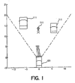
- FIG. 1 is a plan view of an exemplary application of the present invention.
- four radar sensors 103 are positioned in a line in the front end of an automobile 101.
- the radar sensors may be pulsed or variable frequency sensors so that they can detect and distinguish multiple reflected wave fronts in order to provide range measurements to multiple objects 111.
- each sensor is a short range 24 GHz pulse radar, such as Model MLAU0003-006 manufactured by M/A-COM of Lowell, Massachusetts.
- each sensor emits a very short radio frequency (RF) pulse and then detects reflections of that pulse back to the sensor.
- the sensor determines the delay between the issuance of the pulse and the reflected wave fronts and calculates the distances to the objects off of which the reflected wave pulses reflected.
- the range of the sensors should be limited to some reasonable distance based on the application. This can be done by discarding any reflected wave fronts below a predetermined magnitude and/or received after a predetermined delay. Alternately or in addition, the number of range measurements can be limited to a particular number, e.g., the ten closest objects (reflected wave fronts). Further, since automobiles are earthbound, in an automotive application it is often reasonable to assume a two dimensional environment without incurring a substantial loss of useful information.
- the use of more than two sensors helps eliminate situations where readings from two different sensors can only reduce the location of the potential location of the object to two possible locations rather than one.
- the use of more than two sensors provides the means to reduce false objects in accordance with the present invention when range readings from different sensors of different objects are interpreted as a false object. We have found, that, in the automotive field, four sensors arranged in a line in the bumper of an automobile provide good performance.
- FIG. 2 is a block diagram of an intelligent vehicle control system in accordance with the present invention. It comprises four range sensors 201, 203, 205, and 207 and a digital processor 209 coupled to receive the sensors' range measurement outputs.
- the digital processor 209 takes those measurements, and runs them through an algorithm to create a map of objects in the field of view of the sensors.
- the processor 209 might output that map to a tracking processor 211 that compares the map to previous maps to track the velocity and direction of the objects and generates signals for controlling other components 213 of the automobile, such as the brakes and accelerator, in order to implement the aforementioned stop & go vehicle control system.
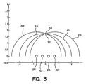
- Figure 3 illustrates a simple simulated scenario involving a single object 302 viewed by a four sensor array.
- Boxes 201, 203, 205, and 207 indicate the location of the four sensors, respectively.
- Semicircles 309, 311, 313, and 315 represent the range observation from the four sensors 201, 203, 205, and 207, respectively.
- the center of each range semicircle is the position of the sensor that generated the observation.
- all four range semicircles intersect at a single point 321. That point is the location of the detected object 302 with respect to the sensor array.
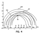
- Figure 4 represents a more realistic environment encountered by an automobile. However, even the environment depicted in Figure 4 is rather simplified.
- the same four sensors 201, 203, 205, and 207 detect two objects, namely, a person 401 and pole 403.
- each of the four sensors 201, 203, 205, and 207 should detect the two objects and only the two objects, i.e., each sensor should generate two accurate range semicircles.
- there is a high probability that one or more of the sensors may (a) not detect one or more of the objects, (b) receive two or more reflections from a single object (particularly if the object is large and/or has a complex shape), and/or (3) simply receive false telemetry.
- the first step of trilateration can generate a map such as the map illustrated in Figures 3 and 4 , further mathematical manipulation of that data is necessary to make reasonable assumptions about which combinations of range circles of different sensors correspond to actual objects and what is the actual location of that object.
- Figure 5 is a simple flow diagram breaking down a trilateration algorithm in accordance with the present invention that generates a list of actual objects from the sensor range measurements.
- Figure 5 basically is a breakdown of the steps that occur in processor 209 of Figure 2 .
- the first step 501 in the process is parsing through the range measurements of the plurality of sensors to identify which range semicircles might correspond to the same object in order to create a list of potential objects.
- Certain assumptions usually can be made to simplify this first step.
- the first reasonable assumption is that all of the range measurements upon which a potential object is based must be from different sensors.
- circles from different sensors that do not intersect with each other do not correspond to the same object. Note that both of these assumptions are not necessarily true in all cases. However, in the overall scheme, tend not to lead to significant error.
- potential objects only if they correspond to three or four sensor readings, i.e., we exclude any potential objects that are based on only two sensor readings. In a preferred embodiment of the invention, however, potential objects that are based on only two sensor readings are considered in a distinct algorithm that separately identifies and validates potential objects that are based on only two sensor readings.
- any two range measurements (or semicircles) from two or more sensors that differ by more than the spacing between the sensors will not intersect.
- any one or more of the sensors may detect fewer than ten reflected wave fronts.
- the number of potential objects generated in this first phase is likely to be substantially less than the potential maximum number, but still could number in the hundreds in a real world situation.
- a list of potential objects is generated based on the pertinent range measurements and a location is assigned to each potential object.
- Several algorithms for estimating location based on range measurements that do not intersect perfectly at a single point are known. Any such suitable algorithm may be employed.
- the specific location that is determined for each potential object is a nonlinear problem that can be solved using an iterative least-squares method, such as the Levenberg-Marquardt method. See, for example, William Press et al, "Numerical Recipes in C", Cambridge University Press, 1999 . However, we choose a simpler algorithm in order to reduce computational burden.
- the potential object location is calculated using only the range measurement from the two sensors most distant from each other (i.e., the two outermost sensors) of the three or four sensors upon which the potential object is based. Recall that, in a preferred embodiment, for a potential object to even make it on to the list of potential objects, it must be based on intersecting semicircles of three or four different sensors.
- the possible existence of an object is based on three or four sensor readings, but the assumed location of that potential object is calculated using only two of those range readings, namely the ones from the outermost sensors, and only these two range readings must intersect.
- a Monte-Carlo simulation indicates that the above-described outermost sensor method produces location results the accuracy of which is degraded by less than ten percent compared to the iterative Levenberg-Marquardt algorithm.
- the second phase of the trilateration technique of the present invention is sorting or ordering the list of potential objects according to a metric that provides a reasonable estimate of the likelihood that the potential object corresponds to an actual object (hereinafter termed a "rank metric").
- a metric that provides a reasonable estimate of the likelihood that the potential object corresponds to an actual object
- rank metric There are many well-known mathematical algorithms for this purpose.
- a cumulative error for each potential object is calculated.
- the cumulative error is representative of the difference between the range measurements upon which the particular potential object is based and the assigned location of that potential object as determined in the first step 501. More specifically, one simple, yet effective algorithm for generating a cumulative error is a sum of the squares of the errors (or SSE) algorithm.
- the SSE of a potential object that is based on the three readings cannot be compared directly to the SSE of a potential object that is based on the four readings.
- the SSE's can be normalized, for instance, by dividing the SSE by the number of sensor readings upon which the potential object is based.
- the metric is calculated as the sum of the squared errors of the inner sensor range(s) with respect to the location of the potential object.
- Each square error term is further normalized by dividing by sensor-measurement variance.
- the rank metric can be considered to be the sum of one or two random variables, each having zero mean and unity variance. If it is assumed that each variable is also normal and independent, then the ranking metric has a chi-square distribution. Specifically, a three sensor metric has a chi-square distribution with one degree of freedom (from its one inner sensor), whereas a four sensor metric has two degrees of freedom.
- the rank metric of both three and four sensor potential objects is advantageous for the rank metric of both three and four sensor potential objects to have the same statistical distribution. This would permit these objects to be compared directly to each other using the metric, without bias favoring either kind.
- the ranking metric of three sensor objects is mapped to the equivalent chi-square value having two degrees of freedom.
- the mapping function can be implemented by a polynomial approximation.
- the list of potential objects is ordered from lowest metric to highest metric, i.e., from smallest error to largest error.
- This ordered list essentially is the output of 503.
- Elimination is the third and final step of the trilateration algorithm and is illustrated at 505 in Figure 5 .
- the elimination algorithm in accordance with the invention is actually quite simple mathematically.
- the highest ranked potential object on the list e.g., the potential object having the lowest cumulative error
- Every other potential object on the list having a lower rank and which is based on any one or more of the range measurements upon which the selected object is based is assumed to be a false object and is removed from the potential object list.
- the next highest ranking potential object on the list is assumed to correspond to an actual object.
- every other potential object on the list having a lower rank and which is based on any one or more of the range measurements upon which that selected object was based is also removed from the list. The process continues until all objects on the list have been either selected as an actual object or removed from the list.
- the above described trilateration algorithm was applied to the example illustrated in Figure 4 , in which an automobile with four sensors 201. 203, 205, 207 is facing a person 401 and a pole 403.
- the algorithm identified two objects as shown in the Figure. Accordingly, the algorithm generated a perfectly accurate map of this particular environment. Specifically, it correctly identified point objects at the location of the pole and the person.
- the pole 403 in this experiment was a three inch schedule-40 PVC pole.
- This pole has a small radar cross-section because of its non-metal material.
- the pole was observed by three sensors 203, 205 and 207, which generated range semicircles 203a, 205a and 207a, but not by the left-most sensor 201. This might have been due to antenna gain considerations.
- the left-most sensor 201 has the least antenna gain toward the pole because its look angle is furthest from bore sight of that particular sensor.
- the person 401 is the closest point object to the sensor array.
- a person does not always present a well-defined reflection point to the sensor array.
- a sensor may detect one leg, the other leg, or the belt buckle. Different sensors may observe different parts of the person.
- the person was observed by all four sensors (see range semicircles 201b, 203b, 205b, and 207b). However, one sensor 205 reported a slightly short range 205b to the person.
- the trilateration algorithm identified the person 401 as a three-sensor object, and did not associate the fourth sensor range reading 205b as belonging to any object.
- the second from left sensor 203 generated two false observations: one halfway between the person and the pole 203c, and one beyond the pole 203d.
- sensors report false observations. This might occur from electromagnetic interference, multipath interference, or sensor imperfections.
- a new trilateration algorithm has been developed to locate objects using range data from a high resolution radar sensor array. Further, the algorithm has been demonstrated to properly resolve objects using real world data from a difficult automotive scenario.
Landscapes
- Engineering & Computer Science (AREA)
- Radar, Positioning & Navigation (AREA)
- Remote Sensing (AREA)
- Computer Networks & Wireless Communication (AREA)
- Physics & Mathematics (AREA)
- General Physics & Mathematics (AREA)
- Radar Systems Or Details Thereof (AREA)
- Position Fixing By Use Of Radio Waves (AREA)
- Testing Or Calibration Of Command Recording Devices (AREA)
Applications Claiming Priority (3)
| Application Number | Priority Date | Filing Date | Title |
|---|---|---|---|
| US10/042,903 US6522288B1 (en) | 2002-01-09 | 2002-01-09 | Method and apparatus for determining location of objects based on range readings from multiple sensors |
| US42903 | 2002-01-09 | ||
| PCT/US2002/040347 WO2003060545A2 (en) | 2002-01-09 | 2002-12-17 | Method and apparatus for determining location of objects based on range reading from mulitiple sensors |
Publications (2)
| Publication Number | Publication Date |
|---|---|
| EP1463959A2 EP1463959A2 (en) | 2004-10-06 |
| EP1463959B1 true EP1463959B1 (en) | 2013-03-20 |
Family
ID=21924350
Family Applications (1)
| Application Number | Title | Priority Date | Filing Date |
|---|---|---|---|
| EP02806462A Expired - Fee Related EP1463959B1 (en) | 2002-01-09 | 2002-12-17 | Method and apparatus for determining location of objects based on range reading from mulitiple sensors |
Country Status (6)
| Country | Link |
|---|---|
| US (1) | US6522288B1 (ja) |
| EP (1) | EP1463959B1 (ja) |
| JP (1) | JP4145800B2 (ja) |
| CN (1) | CN1320370C (ja) |
| AU (1) | AU2002366996A1 (ja) |
| WO (1) | WO2003060545A2 (ja) |
Families Citing this family (30)
| Publication number | Priority date | Publication date | Assignee | Title |
|---|---|---|---|---|
| US6628227B1 (en) * | 2002-07-23 | 2003-09-30 | Ford Global Technologies, Llc | Method and apparatus for determining a target vehicle position from a source vehicle using a radar |
| DE10258287A1 (de) * | 2002-12-13 | 2004-06-24 | Robert Bosch Gmbh | Verfahren und Einrichtung zur Objektdetekrierung |
| JP4371115B2 (ja) * | 2006-03-01 | 2009-11-25 | トヨタ自動車株式会社 | 物体検出装置 |
| US8073564B2 (en) * | 2006-07-05 | 2011-12-06 | Battelle Energy Alliance, Llc | Multi-robot control interface |
| US8271132B2 (en) * | 2008-03-13 | 2012-09-18 | Battelle Energy Alliance, Llc | System and method for seamless task-directed autonomy for robots |
| US7587260B2 (en) | 2006-07-05 | 2009-09-08 | Battelle Energy Alliance, Llc | Autonomous navigation system and method |
| US8355818B2 (en) * | 2009-09-03 | 2013-01-15 | Battelle Energy Alliance, Llc | Robots, systems, and methods for hazard evaluation and visualization |
| US7668621B2 (en) * | 2006-07-05 | 2010-02-23 | The United States Of America As Represented By The United States Department Of Energy | Robotic guarded motion system and method |
| US7974738B2 (en) * | 2006-07-05 | 2011-07-05 | Battelle Energy Alliance, Llc | Robotics virtual rail system and method |
| US7584020B2 (en) * | 2006-07-05 | 2009-09-01 | Battelle Energy Alliance, Llc | Occupancy change detection system and method |
| US7801644B2 (en) * | 2006-07-05 | 2010-09-21 | Battelle Energy Alliance, Llc | Generic robot architecture |
| US7620477B2 (en) * | 2006-07-05 | 2009-11-17 | Battelle Energy Alliance, Llc | Robotic intelligence kernel |
| US8965578B2 (en) | 2006-07-05 | 2015-02-24 | Battelle Energy Alliance, Llc | Real time explosive hazard information sensing, processing, and communication for autonomous operation |
| US7211980B1 (en) * | 2006-07-05 | 2007-05-01 | Battelle Energy Alliance, Llc | Robotic follow system and method |
| NL1032520C2 (nl) * | 2006-09-15 | 2008-03-18 | Thales Nederland Bv | Werkwijze en systeem voor het volgen van een object. |
| JP2008209321A (ja) * | 2007-02-27 | 2008-09-11 | Fujitsu Ltd | 探知測距装置および探知測距プログラム |
| US8101790B2 (en) * | 2007-06-13 | 2012-01-24 | Invista North America S.A.R.L. | Process for improving adiponitrile quality |
| JP5164546B2 (ja) * | 2007-12-07 | 2013-03-21 | クラリオン株式会社 | 測位方法 |
| SE532431C2 (sv) * | 2008-05-30 | 2010-01-19 | Atlas Copco Rock Drills Ab | Metod och anordning för bestämning av en överensstämmelse mellan en representation av en omgivning och nämnda omgivning |
| US8340818B2 (en) * | 2009-04-24 | 2012-12-25 | Robert Bosch Gmbh | Method of accurate mapping with mobile robots |
| US8816895B2 (en) * | 2011-04-15 | 2014-08-26 | Raytheon Company | Target-tracking radar classifier with glint detection and method for target classification using measured target epsilon and target glint information |
| JP5634423B2 (ja) * | 2012-03-02 | 2014-12-03 | 株式会社東芝 | 目標追跡装置、目標追跡プログラム、目標追跡システム、及び目標追跡方法 |
| JP6123133B2 (ja) * | 2013-03-04 | 2017-05-10 | パナソニックIpマネジメント株式会社 | 車両用障害物検知装置および、車両用障害物検知システム |
| JP5950122B2 (ja) * | 2013-12-27 | 2016-07-13 | 株式会社国際電気通信基礎技術研究所 | キャリブレーション装置、キャリブレーション方法およびキャリブレーションプログラム |
| US10156853B2 (en) | 2015-04-02 | 2018-12-18 | Electric 80 S.P.A. | Group for localizing a moving target in a warehouse with automatic guided vehicles |
| WO2019185739A1 (en) * | 2018-03-29 | 2019-10-03 | Sony Corporation | Device, system and method for localization of a target in a scene |
| JP7074593B2 (ja) * | 2018-07-03 | 2022-05-24 | 株式会社Soken | 物体検出装置 |
| JP7111586B2 (ja) * | 2018-11-09 | 2022-08-02 | 株式会社Soken | 物体検出装置 |
| JP7208112B2 (ja) * | 2019-06-19 | 2023-01-18 | 株式会社Soken | 物体検出装置 |
| EP3997483A1 (en) * | 2019-07-12 | 2022-05-18 | Artis LLC | Microsecond time of flight (mtof) sensor |
Family Cites Families (8)
| Publication number | Priority date | Publication date | Assignee | Title |
|---|---|---|---|---|
| US4914604A (en) * | 1988-10-07 | 1990-04-03 | Hughes Aircraft Company | Processor for analyzing angle-only data |
| US5392225A (en) * | 1992-10-20 | 1995-02-21 | E-Sytems, Inc. | Method and apparatus for correlating target data |
| JP2989428B2 (ja) * | 1993-06-17 | 1999-12-13 | 本田技研工業株式会社 | 時分割型fmレーダシステム |
| DE19711467C2 (de) * | 1997-03-20 | 2000-12-07 | Mannesmann Vdo Ag | Verfahren zur Bestimmung des senkrechten Abstandes zwischen einem Objekt und einer sich örtlich verändernden Einrichtung |
| US6055042A (en) * | 1997-12-16 | 2000-04-25 | Caterpillar Inc. | Method and apparatus for detecting obstacles using multiple sensors for range selective detection |
| JP2000292538A (ja) * | 1999-04-07 | 2000-10-20 | Mitsubishi Electric Corp | 車両用障害物検出装置 |
| US6456239B1 (en) * | 1999-08-25 | 2002-09-24 | Rf Technologies, Inc. | Method and apparatus for locating mobile tags |
| DE19949409A1 (de) * | 1999-10-13 | 2001-04-19 | Bosch Gmbh Robert | Verfahren und Vorrichtung zur Objektdetektierung |
-
2002
- 2002-01-09 US US10/042,903 patent/US6522288B1/en not_active Expired - Lifetime
- 2002-12-17 WO PCT/US2002/040347 patent/WO2003060545A2/en active Application Filing
- 2002-12-17 JP JP2003560587A patent/JP4145800B2/ja not_active Expired - Fee Related
- 2002-12-17 CN CNB028279468A patent/CN1320370C/zh not_active Expired - Fee Related
- 2002-12-17 EP EP02806462A patent/EP1463959B1/en not_active Expired - Fee Related
- 2002-12-17 AU AU2002366996A patent/AU2002366996A1/en not_active Abandoned
Also Published As
| Publication number | Publication date |
|---|---|
| AU2002366996A8 (en) | 2003-07-30 |
| WO2003060545A3 (en) | 2003-11-13 |
| EP1463959A2 (en) | 2004-10-06 |
| JP2005515444A (ja) | 2005-05-26 |
| CN1320370C (zh) | 2007-06-06 |
| WO2003060545A2 (en) | 2003-07-24 |
| JP4145800B2 (ja) | 2008-09-03 |
| US6522288B1 (en) | 2003-02-18 |
| CN1636149A (zh) | 2005-07-06 |
| AU2002366996A1 (en) | 2003-07-30 |
Similar Documents
| Publication | Publication Date | Title |
|---|---|---|
| EP1463959B1 (en) | Method and apparatus for determining location of objects based on range reading from mulitiple sensors | |
| US6664918B2 (en) | Method and apparatus for identifying complex objects based on range readings from multiple sensors | |
| US10175348B2 (en) | Use of range-rate measurements in a fusion tracking system via projections | |
| EP1923717B1 (en) | Method and apparatus for discriminating with respect to low elevation target objections | |
| EP2307908B1 (en) | Automotive radar with composite multi-slope fm chirp waveform | |
| US7420501B2 (en) | Method and system for correlating radar position data with target identification data, and determining target position using round trip delay data | |
| EP1954920B1 (en) | System for identifying high-quality phase angle measurements in an interferometric radar system | |
| EP1588188B1 (en) | Method of detecting a target | |
| Folster et al. | An automotive radar network based on 77 GHz FMCW sensors | |
| KR100852103B1 (ko) | 고도 추정 시스템 및 방법 | |
| JP6699904B2 (ja) | レーダ装置及びそのレーダ信号処理方法 | |
| EP3483630B1 (en) | Detection of parking slot configuration based on repetitive patterns | |
| EP3982160A1 (en) | Method and system for indoor multipath ghosts recognition | |
| EP3775989B1 (en) | Device, system and method for localization of a target in a scene | |
| US20030112183A1 (en) | Localisation of a signal emitting source | |
| US10551493B2 (en) | Widely spaced radar nodes with unambiguous beam pattern | |
| US10401472B2 (en) | System and method for range and angle determination to an array of radio receivers | |
| US20230026149A1 (en) | Radar mount-angle calibration | |
| Fritsche et al. | Comparison of two radar-based scanning-techniques for the use in robotic mapping | |
| Leba et al. | Receivers placement for UAV localization in a surveillance area | |
| Ren et al. | Discrimination of Automotive Radar Distributed Targets | |
| US20240159889A1 (en) | Radar Detection Multipath Detector | |
| EP1849021B1 (fr) | Procede de localisation d'un objet mobile a partir de mesures de distance et de vitesse bistatiques de cet objet a l'aide d'un systeme multistatique | |
| Soysal et al. | Information analysis in passive radar networks for target tracking | |
| Lee et al. | Radio Slam with Hybrid Sensing for Mixed Reflection Type Environments |
Legal Events
| Date | Code | Title | Description |
|---|---|---|---|
| PUAI | Public reference made under article 153(3) epc to a published international application that has entered the european phase |
Free format text: ORIGINAL CODE: 0009012 |
|
| 17P | Request for examination filed |
Effective date: 20040629 |
|
| AK | Designated contracting states |
Kind code of ref document: A2 Designated state(s): AT BE BG CH CY CZ DE DK EE ES FI FR GB GR IE IT LI LU MC NL PT SE SI SK TR |
|
| AX | Request for extension of the european patent |
Extension state: AL LT LV MK RO |
|
| 17Q | First examination report despatched |
Effective date: 20080605 |
|
| RAP1 | Party data changed (applicant data changed or rights of an application transferred) |
Owner name: AUTOLIV ASP, INC. |
|
| GRAP | Despatch of communication of intention to grant a patent |
Free format text: ORIGINAL CODE: EPIDOSNIGR1 |
|
| GRAS | Grant fee paid |
Free format text: ORIGINAL CODE: EPIDOSNIGR3 |
|
| GRAA | (expected) grant |
Free format text: ORIGINAL CODE: 0009210 |
|
| AK | Designated contracting states |
Kind code of ref document: B1 Designated state(s): DE FR GB |
|
| REG | Reference to a national code |
Ref country code: GB Ref legal event code: FG4D |
|
| REG | Reference to a national code |
Ref country code: DE Ref legal event code: R096 Ref document number: 60244676 Country of ref document: DE Effective date: 20130516 |
|
| PLBE | No opposition filed within time limit |
Free format text: ORIGINAL CODE: 0009261 |
|
| STAA | Information on the status of an ep patent application or granted ep patent |
Free format text: STATUS: NO OPPOSITION FILED WITHIN TIME LIMIT |
|
| PGFP | Annual fee paid to national office [announced via postgrant information from national office to epo] |
Ref country code: FR Payment date: 20131011 Year of fee payment: 12 |
|
| 26N | No opposition filed |
Effective date: 20140102 |
|
| REG | Reference to a national code |
Ref country code: DE Ref legal event code: R097 Ref document number: 60244676 Country of ref document: DE Effective date: 20140102 |
|
| GBPC | Gb: european patent ceased through non-payment of renewal fee |
Effective date: 20131217 |
|
| PG25 | Lapsed in a contracting state [announced via postgrant information from national office to epo] |
Ref country code: GB Free format text: LAPSE BECAUSE OF NON-PAYMENT OF DUE FEES Effective date: 20131217 |
|
| REG | Reference to a national code |
Ref country code: FR Ref legal event code: ST Effective date: 20150831 |
|
| PG25 | Lapsed in a contracting state [announced via postgrant information from national office to epo] |
Ref country code: FR Free format text: LAPSE BECAUSE OF NON-PAYMENT OF DUE FEES Effective date: 20141231 |
|
| REG | Reference to a national code |
Ref country code: DE Ref legal event code: R082 Ref document number: 60244676 Country of ref document: DE Representative=s name: MUELLER VERWEYEN PATENTANWAELTE PARTNERSCHAFT , DE Ref country code: DE Ref legal event code: R081 Ref document number: 60244676 Country of ref document: DE Owner name: VEONEER US, INC., SOUTHFIELD, US Free format text: FORMER OWNER: AUTOLIV ASP, INC., OGDEN, UTAH, US |
|
| PGFP | Annual fee paid to national office [announced via postgrant information from national office to epo] |
Ref country code: DE Payment date: 20201223 Year of fee payment: 19 |
|
| REG | Reference to a national code |
Ref country code: DE Ref legal event code: R119 Ref document number: 60244676 Country of ref document: DE |
|
| PG25 | Lapsed in a contracting state [announced via postgrant information from national office to epo] |
Ref country code: DE Free format text: LAPSE BECAUSE OF NON-PAYMENT OF DUE FEES Effective date: 20220701 |