EP1463018B1 - Vorrichtung zur audiovisuellen Präsentation von Ton und Bild - Google Patents
Vorrichtung zur audiovisuellen Präsentation von Ton und Bild Download PDFInfo
- Publication number
- EP1463018B1 EP1463018B1 EP04006253A EP04006253A EP1463018B1 EP 1463018 B1 EP1463018 B1 EP 1463018B1 EP 04006253 A EP04006253 A EP 04006253A EP 04006253 A EP04006253 A EP 04006253A EP 1463018 B1 EP1463018 B1 EP 1463018B1
- Authority
- EP
- European Patent Office
- Prior art keywords
- monitor
- movement
- memory
- screen
- control unit
- Prior art date
- Legal status (The legal status is an assumption and is not a legal conclusion. Google has not performed a legal analysis and makes no representation as to the accuracy of the status listed.)
- Expired - Lifetime
Links
Images

Classifications
-
- G—PHYSICS
- G09—EDUCATION; CRYPTOGRAPHY; DISPLAY; ADVERTISING; SEALS
- G09F—DISPLAYING; ADVERTISING; SIGNS; LABELS OR NAME-PLATES; SEALS
- G09F27/00—Combined visual and audible advertising or displaying, e.g. for public address
Definitions
- the present invention relates to a device for audiovisual presentation of sound and image, in particular for advertising purposes, with a memory and a screen for displaying image information from the memory.
- the invention provides a completely novel audiovisual presentation device in which picture and sound contents are tuned to the movement of the display medium, the screen.
- the advertised product is thus always present and offers a highly efficient advertising platform. Since the display medium in the form of the screen according to the invention represents the actor of the presentation, it attracts the attention of the public concerned, be it professionals or end users, to an extent that is not feasible by the previous audiovisual presentation device with static screen through the long-standing habituation effect ,
- the screen drive unit comprises a rotary drive for rotating the screen from an axis perpendicular to the screen, preferably around the screen center, so that this presentation medium can be correlated with the image information and optionally the sound information.
- the movement in this case the Rotational motion of the screen is replicated to the representation of image and / or sound on the screen.
- a modification of the image information read from the image memory takes place as a function of the screen movement or position, in particular by disassembling and reassembling or synthesizing the decomposed image content as a function of the screen movement.
- the image information displayed on it is subdivided into image segments, which are moved apart during a further rotation of the screen and are reassembled to the original image during a subsequent movement of the screen.
- This dynamic image design as a function of the screen movement represents a novel form of presentation that draws a viewer involuntarily into the action on the screen.
- the screen may attractively follow the ride of a skier or a bob by simulating the rhythmic motion of this sports device through an angular limited rotation of the screen in a clockwise and counterclockwise direction.
- the rotary drive provided for the rotary movement of the screen preferably comprises a low-friction rotary bearing in order to be able to realize a screen rotation in the most arbitrary speed, acceleration and direction possible.
- a rotary transformer for the transmitted between the control unit and the screen signals or data and / or its Power provided.
- the signal or data transmission can alternatively be made without contact.
- the correlation between screen movement and image information is implemented by implementing a control loop for the synchronization of screen movement and image information.
- control loop for a dynamic synchronization of the screen movement is designed with the image information such that in addition to a constant speed of this movement (for example, rotational movement) whose acceleration and deceleration are freely definable.
- control loop provides bidirectional data transmission between the screen drive unit and the control unit with constant comparison of the actual value of the image information with the target value of the screen movement and the actual value of the screen movement with the target value of the image information in front.
- control loop according to the invention is preferably realized in the form of a programmable software.
- control loop or the control unit preferably with the involvement of a computer, especially a personal computer.
- image and possibly the sound information is stored in a memory of the computer as well as the motion data for the screen drive.
- a content player (or a data player) acted upon by the contents of the memory is implemented, above all, as software, which stores the image and, if appropriate, audio data stored in the memory of the computer and the movement data on the basis of timeline data (clock data or time code data) plays, which are also stored in memory.
- the computer preferably implements a motion player (eg, as software) that communicates bidirectionally with the output of the content player and the screen drive unit based on a common trigger signal for memory, content player, and motion player.
- a motion player eg, as software
- the sound information is included in the control of the screen drive by computer.
- the moving screen according to the invention does not present a safety risk
- safety information is exchanged between the drive unit and / or screen and control unit, especially with respect to maximum speed, acceleration and safety distance to the environment, the drive unit possibly being stopped when the maximum values are exceeded becomes.
- the screen is preferably a matrix display, especially a plasma or LCD display.
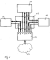
- the audiovisual presentation device shown in Fig. 1 comprises a screen 10, preferably in the form of a matrix display, such as a plasma or LCD display, a drive unit 11 for moving the matrix display 10, a control unit 12 for controlling the movement of the Screen 10 via the drive unit 11 and an audio unit 13 for reproducing sound information.
- Sound and image information as well as movement data are stored, preferably in digital format, in a memory 14, which is in data communication with the control unit 12, as indicated by an arrow, which starts from the memory 14 and points to the control unit 12.
- the control unit 12 communicates with the screen 10, the drive unit 11 and the audio unit 13 as indicated by arrows, partly in two-way communication, and the entirety of these communication means is schematically summarized as the central communication unit 15 in FIG.
- the communication terminals of the control unit 12 are designated A, B, C, D, E, F, K and form the starting point or end point of the arrows used in FIG. 1 to designate the communication.
- A denotes a communication line from the control unit 12 to the audio unit 13, and this communication line is for transmitting a warning signal from the control unit 12 to the audio unit 13.
- This warning signal is generated in the control unit 12 together with a fault message signal, which emanates from the screen 10 and is transmitted via the communication line K to the control unit 12.
- An audio signal is transmitted from the memory 14 to the audio unit 13 via the communication line B through the control unit 12.
- a non-stop actuation signal is transmitted from the control unit 12 to the drive unit 11 via the communication line C.
- An action signal is transmitted from the control unit 12 to the drive unit 11 via the communication line D.
- a reaction signal corresponding to this action is transmitted from the drive unit 11 to the control unit 12 via the communication line E.
- a video signal is transmitted to the screen 10 via the communication line F from the control unit 12 (originating from the memory 14).
- Another communication line L exists, starting from the drive unit 11 to the screen 10 and schematically represents the movement, which transmits the drive unit 11 to the screen 10.
- the audiovisual presentation device shown schematically in Fig. 1 is used to move the screen 10 via the drive unit 11 in response to the image information stored in the image memory and vice versa for transmitting the screen movement via the drive unit 11 to the control unit 12, to modify in this way image and / or sound data or audio data depending on the screen movement, for example, to break into segments and then put together again depending on the further course of motion of the screen 10 to a coherent image.
- the control unit 12 in the form of a computer preferably a personal computer is realized, which contains the data memory 14 in the form of a hard disk drive.
- the data memory 14 is connected to an intermediate unit, which in the present case is designated as a content player (data playback unit) 16.
- This content player 16 has three outputs, a first of which is connected to a motion player, in the present case a rotary player 17.
- the connection between rotation player 17 and content player 16 is a bidirectional connection.
- the second output of the content player 16 is connected to a graphics card 18 and the third output of the content player 16 is connected to a sound card 19.
- the rotary player 17 has a bidirectional output, which is connected to a preferably external controller 20, which in turn is connected on the output side to an electric motor 21 of the drive unit 11.
- the controller 20 as well as the motor 21 is integrated into the drive unit 11, which is otherwise in drive connection with the screen 10, in the present embodiment to rotate about a vertical axis passing through its center.
- Signals between the electric motor 21 and the screen 10 are transmitted, for example via a rotary transformer or contactless.
- the power supply for the screen 10 is also transmitted from a rotary transformer or the rotary transformer for signal transmission from the electric motor 21 to the screen 10.
- Corresponding image information passes from the graphics card 18 to the screen 10.
- the output of the sound card 19 is connected to an external power amplifier or a power amplifier 22, which drives a sound transducer 23 on the output side.
- the output stage 22 is integrated in the sound transducer 23.
- the memory 14 contains rotation data supplied to a rotation section 24 (in the general case a moving section) of the content player 16. Similarly, image data contained in the memory 14 is supplied to an image portion 25 of the content player 16. Video data is supplied to a corresponding video section 26 of the content player 16. The image data and the video data supplied to the image section 25 and the video section 26 of the content player 16 are image information including still image information (25) and moving image information (26). Audio data contained in the memory 14 is supplied to a sound section 27 of the content player. Data from the image portion 25 and video portion 26 are respectively supplied to the graphics card 18 and data from the sound portion 27 are supplied to the sound card 19.
- the memory 14 also stores timeline data (timing data) supplied to a timeline 28 in the content player 16 and for synchronizing the data of the content player with each other and with the rotary player 17 and the external motor 21 and the Screen 10 (its position) are used, as explained in more detail below.
- timeline data timing data supplied to a timeline 28 in the content player 16 and for synchronizing the data of the content player with each other and with the rotary player 17 and the external motor 21 and the Screen 10 (its position) are used, as explained in more detail below.
- initialization signals are supplied from the memory via an initialization signal line 29 to the content player 16, the rotary player 17 and the controller 20.
- the rotation player 17 is connected to a limit value memory 30 which holds maximum values for the rotation signals supplied to the electric motor 21 by the rotary player 17 via the controller 20, which maximum values are always compared with the actual values of the rotation player 17 and optionally used to block its output signals in order to prevent unwanted movement or movement conditions of the screen 10, which is set in rotation by the motor 11.
- the device according to the invention shown in FIG. 2 is in particular designed to dynamically synchronize its hardware components. Since, due to the objective of controlling screen motion and image information for the screen in favor of a highly efficient advertising platform, conventional distribution of image (and sound) contents as well as control signals to the drive unit is sufficient 11, because the temporal play behavior depends on some factors of the hardware components, such as resolution (in particular of the screen), different data formats and the like, and because a temporal prediction can not be made. For this reason, a control loop is implemented which dynamically synchronizes image content and motion, in this case rotational movement of the screen.
- This control loop as shown in FIG. 2, has a bidirectional structure. That is, it is constantly compared both the actual value of the image content with the target value of the rotational movement and, conversely, the actual value of the rotational movement with the target value of the image content.
- the control loop consists essentially of the players 16 and 17 and the control unit 12 of FIG. 2.
- the drive action, ie the angular velocity, the acceleration, the deceleration and the direction of rotation of the electric motor 21 and thus of the screen 10 are transmitted from the rotation player to the motor control, and the reaction (the angular position) is simultaneously reported back to the rotation player in this way.
- any rotation of the screen 10 by the rotation data stored in the memory 14 can be dependent on the image information stored in this memory (image data and / or video data).
- the rotational movement of the screen 10 for modifying the image information can be used.
Landscapes
- Physics & Mathematics (AREA)
- General Physics & Mathematics (AREA)
- Engineering & Computer Science (AREA)
- Theoretical Computer Science (AREA)
- Controls And Circuits For Display Device (AREA)
- Stereophonic System (AREA)
- Electrically Operated Instructional Devices (AREA)
Description
- Die vorliegende Erfindung betrifft eine Vorrichtung zur audiovisuellen Präsentation von Ton und Bild, insbesondere zu Werbezwecken, mit einem Speicher und einem Bildschirm zum Anzeigen von Bildinformation aus dem Speicher.
- Es ist bekannt, zu audiovisuellen Präsentationszwecken Bildschirme bzw. Displays einzusetzen, die in Gestalt von Röhren oder zunehmend Flachbildschirmen, vor allem LCD- und TFT-Flachbildschirmen zur Verfügung stehen. Über diese Bildschirme werden beispielsweise Werbebotschaften an Verkaufsstätten, auf Messen und in öffentlichen Verkehrsmitteln präsentiert. Diese Bildschirme werden üblicherweise stationär am Zielort eingesetzt und von einem Videoplayer oder einem DVD-Player mit Tonund Bildmaterial beschickt. Diese Videoinformation wird regelmäßig in der auf Datenträger aufgezeichneten Konfiguration unverändert über den Bildschirm wiedergegeben. Diese weit verbreitete Präsentationsart hat aufgrund ihres langjährigen unveränderten Einsatzes stark an Attraktivität verloren, weil das angesprochene Publikum nicht zuletzt aufgrund des Einsatzes von Fernsehern im heimischen Bereich an diese Präsentationsart gewöhnt ist, ihr also in der Regel keine besondere Aufmerksamkeit mehr schenkt.
- Es besteht deshalb ein Bedarf an einer audiovisuellen Präsentationsvorrichtung, die geeignet ist, die Aufmerksamkeit von sowohl Fachkreisen wie Endabnehmern im Hinblick auf Werbebotschaften zu erwecken.
- Eine Aufgabe der vorliegenden Erfindung besteht deshalb darin, eine Vorrichtung zur audiovisuellen Präsentation von Ton und Bild der eingangs genannten Art zu schaffen, das eine hochgradig effizient Werbeplattform darstellt.
- Gelöst wird diese Aufgabe durch die Merkmale des Anspruchs 1. Vorteilhafte Weiterbildungen der Erfindung sind in den Unteransprüchen angegeben.
- Die Erfindung stellt demnach mit anderen Worten eine vollständig neuartige audiovisuelle Präsentationsvorrichtung bereit, bei der Bild- und Toninhalte auf die Bewegung des Darstellungsmediums, des Bildschirms, abgestimmt sind. Das beworbene Produkt ist hierdurch stets präsent und bietet eine höchst effiziente Werbeplattform. Da das Darstellungsmedium in Gestalt des Bildschirms erfindungsgemäß den Handlungstrager der Prasentation darstellt, zieht es die Aufmerksamkeit des betroffenen Publikums, seien es Fachkreise oder Endabnehmer, in einem Maße auf sich, das durch die bisherige audiovisuelle Präsentationsvorrichtung mit statischem Bildschirm durch den langjährigen Gewöhnungseffekt nicht realisierbar ist.
- Gemäß einer bevorzugten Ausgestaltung der Erfindung umfasst die Bildschirm-Antriebseinheit einen Drehantrieb zum Rotieren des Bildschirms von einer Achse senkrecht zum Bildschirm, vorzugsweise um das Bildschirmzentrum, so dass dieses Darstellungsmedium mit der Bildinformation und gegebenenfalls der Toninformation korreliert werden kann. Alternativ oder zusätzlich hierzu wird erfindungsgemäß die Bewegung, vorliegend die Drehbewegung des Bildschirms rückabgebildet auf die Darstellung von Bild und/oder Ton auf dem Bildschirm. Mit anderen Worten erfolgt eine Modifikation der aus dem Bildspeicher gelesenen Bildinformation in Abhängigkeit der Bildschirmbewegung bzw. -position , vor allem durch Zerlegen und neues Zusammensetzen bzw. Synthetisieren des zerlegten Bildinhalts in Abhängigkeit der Bildschirmbewegung. Beispielsweise wird während eines Bewegungssegments des Bildschirms die auf ihm angezeigte Bildinformation in Bildsegmente unterteilt, die bei einer weiteren Drehung des Bildschirms auseinanderbewegt und bei einer darauf folgenden Bewegung des Bildschirms wieder zum ursprunglichen Bild zusammengesetzt werden. Diese dynamische Bildgestaltung in Abhängigkeit der Bildschirmbewegung stellt eine neuartige Präsentationsform dar, die einen Betrachter unwillkürlich in das Geschehen auf dem Bildschirm hineinzieht. Eine Übertragung des Bildinhalts auf die Bildschirmbewegung, vorliegend die Drehbewegung des Bildschirms, um diese Bewegung zu modifizieren, führt zu einem ähnlichen visuell interessanten Effekt. Beispielsweise kann der Bildschirm in attraktiver Weise der Fahrt eines Skifahrers oder eines Bobs folgen, indem er die rhythmische Bewegung dieses Sportgeräts simuliert durch eine winkelmaßig begrenzte Drehung des Bildschirms im Uhrzeigersinn und gegen den Uhrzeigersinn.
- Der für die Drehbewegung des Bildschirms vorgesehene Drehantrieb umfasst bevorzugt ein reibungsarmes Drehlager, um eine Bildschirmdrehbewegung in möglichst beliebiger Geschwindigkeit, Beschleunigung und Richtung realisieren zu können.
- Im Fall eines drehbaren Bildschirms ist vorteilhafterweise ein Drehübertrager für die zwischen der Steuereinheit und dem Bildschirm übertragenen Signale bzw. Daten und/oder dessen Stromversorgung vorgesehen. Die Signal- bzw. Datenübertragung kann alternativ auch kontaktfrei erfolgen.
- Gemäß einem besonders vorteilhaften Aspekt der Erfindung erfolgt die Korrelation zwischen Bildschirmbewegung und Bildinformation durch Implementierung einer Regelschleife zur Synchronisation von Bildschirmbewegung und Bildinformation.
- Bevorzugt ist die Regelschleife für eine dynamische Synchronisation der Bildschirmbewegung mit der Bildinformation derart ausgelegt, dass neben einer gleichbleibenden Geschwindigkeit dieser Bewegung (beispielsweise Drehbewegung) deren Beschleunigen und Abbremsen frei definierbar sind.
- Gemäß einer vorteilhaften Weiterbildung dieses Aspekts der Erfindung sieht die Regelschleife eine bidirektionelle Datenübertragung zwischen Bildschirm-Antriebseinheit und Steuereinheit unter ständigem Vergleich des Ist-Werts der Bildinformation mit dem Soll-Wert der Bildschirmbewegung und des Ist-Werts der Bildschirmbewegung mit dem Soll-Wert der Bildinformation vor.
- Die erfindungsgemäße Regelschleife ist bevorzugt in Gestalt einer programmierbaren Software verwirklicht.
- Implementiert ist die Regelschleife bzw. die Steuereinheit bevorzugt unter Einbeziehung eines Computers, vor allem eines Personal Computers. In diesem Fall ist die Bild- und gegebenenfalls die Toninformation in einem Speicher des Computers ebenso gespeichert wie die Bewegungsdaten für den Bildschirmantrieb.
- In dem Computer ist ein vom Inhalt des Speichers beaufschlagter Content-Player (bzw. ein Daten-Abspielgerät) vor allem als Software implementiert, der die im Speicher des Computers gespeicherten Bild- und gegebenenfalls Tondaten sowie die Bewegungsdaten auf Grundlage von Timeline-Daten (Taktdaten bzw. Zeitcode-Daten) abspielt, die ebenfalls im Speicher abgelegt sind.
- Ferner ist im Computer bevorzugt ein Bewegungsplayer (beispielsweise als Software) implementiert, der mit dem Ausgang des Content-Players und der Bildschirm-Antriebseinheit bidirektionell auf Grundlage eines gemeinsamen Auslösesignals für Speicher, Content-Player und Bewegungsplayer kommuniziert.
- Bevorzugt ist die Toninformation in die Steuerung des Bildschirm-Antriebs per Computer einbezogen.
- Damit der erfindungsgemaß bewegte Bildschirm kein Sicherheitsrisiko darstellt, ist erfindungsgemäß vorgesehen, dass zwischen Antriebseinheit und/oder Bildschirm und Steuereinheit Sicherheitsinformation, vor allem in Bezug auf maximale Geschwindigkeit, Beschleunigung und Sicherheitsabstand zur Umgebung ausgetauscht werden, wobei die Antriebseinheit bei Überschreiten der Maximalwerte gegebenenfalls still gesetzt wird.
- Um Maße und Gewichte des Bildschirms möglichst klein zu halten, dabei jedoch eine optimal große Bildschirmanzeige zu gewährleisten, ist der Bildschirm bevorzugt ein Matrix-Display, vor allem ein Plasma- oder LCD-Display.
- Die Erfindung wird nachfolgend anhand der Zeichnung beispielhaft näher erläutert; in dieser zeigen:
- Fig. 1 schematisch ein Blockdiagramm der erfindungsgemäßen audiovisuellen Präsentationsvorrichtung, und
- Fig. 2 ein detaillierteres Blockschaltbild der Vorrichtung von Fig. 1.
- Die in Fig. 1 gezeigte audiovisuelle Präsentationsvorrichtung umfasst einen Bildschirm 10, bevorzugt in Gestalt eines Matrix-Displays, wie etwa eines Plasma- oder LCD-Displays, eine Antriebseinheit 11 zum Bewegen des Matrix-Displays 10, eine Steuereinheit 12 zum Steuern der Bewegung des Bildschirms 10 über die Antriebseinheit 11 und eine Audioeinheit 13 zum Wiedergeben von Toninformation. Ton- und Bildinformation sowie Bewegungsdaten sind, jeweils bevorzugt in digitalem Format, in einem Speicher 14 abgelegt, der in Datenkommunikation mit der Steuereinheit 12 steht, wie durch einen Pfeil bezeichnet, der von dem Speicher 14 ausgeht und zur Steuereinheit 12 zeigt.
- Die Steuereinheit 12 steht mit dem Bildschirm 10, der Antriebseinheit 11 und der Audioeinheit 13, wie durch Pfeile bezeichnet, in Kommunikation, teilweise in Zwei-Wege-Kommunikation, und die Gesamtheit dieser Kommunikationsmittel ist schematisch als zentrale Kommunikationseinheit 15 in Fig. 1 zusammengefasst. Die Kommunikationsanschlüsse der Steuereinheit 12 sind mit A, B, C, D, E, F, K bezeichnet und bilden Ausgangspunkt bzw. Endpunkt der in Fig. 1 zur Bezeichnung der Kommunikation verwendeten Pfeile.
- Im einzelnen ist mit A eine Kommunikationsleitung von der Steuereinheit 12 zu der Audioeinheit 13 bezeichnet, und diese Kommunikationsleitung dient zur Übertragung eines Warnsignals von der Steuereinheit 12 zur Audioeinheit 13. Dieses Warnsignal wird in der Steuereinheit 12 gemeinsam mit einem Störmeldungssignal erzeugt, das vom Bildschirm 10 ausgeht und über die Kommunikationsleitung K zur Steuereinheit 12 übertragen wird.
- Ein Audiosignal wird aus dem Speicher 14 mittels der Steuereinheit 12 über die Kommunikationsleitung B zu der Audioeinheit 13 übertragen.
- Ein Non Stopp Betätigungssignal wird von der Steuereinheit 12 zu der Antriebseinheit 11 über die Kommunikationsleitung C übertragen.
- Ein Aktionssignal wird von der Steuereinheit 12 über die Kommunikationsleitung D zu der Antriebseinheit 11 übertragen. Ein dieser Aktion entsprechendes Reaktionssignal wird von der Antriebseinheit 11 über die Kommunikationsleitung E zu der Steuereinheit 12 übertragen. Ein Videosignal wird über die Kommunikationsleitung F von der Steuereinheit 12 (vom Speicher 14 herrührend) zu dem Bildschirm 10 übertragen.
- Eine weiterer Kommunikationsstrang L existiert ausgehend von der Antriebseinheit 11 zu dem Bildschirm 10 und stellt schematisch die Bewegung dar, welche die Antriebseinheit 11 auf den Bildschirm 10 überträgt.
- Die in Fig. 1 schematisch dargestellte audiovisuelle Präsentationsvorrichtung dient zur Bewegung des Bildschirms 10 über die Antriebseinheit 11 in Abhängigkeit der im Bildspeicher gespeicherten Bildinformation und umgekehrt zur Übertragung der Bildschirmbewegung über die Antriebseinheit 11 zur Steuereinheit 12, um auf diese Weise Bild- und/oder Tondaten bzw. Audiodaten abhängig von der Bildschirmbewegung zu modifizieren, beispielsweise in Segmente zu zerlegen und anschließend wieder abhängig von dem weiteren Bewegungsverlauf des Bildschirms 10 zu einem zusammenhängenden Bild zusammen zu setzen.
- Die Steuerung des Bildschirms und dessen Antrieb über die Steuereinheit 12 ausgehend von den im Speicher 14 bereitstehenden Daten ist nachfolgend unter Bezug auf Fig. 2 näher erläutert.
- In Fig. 2 ist die Steuereinheit 12 in Gestalt eines Computers, bevorzugt eines Personal Computers verwirklicht, der den Datenspeicher 14 in Gestalt eines Festplattenantriebs enthält. Ausgangsseitig ist der Datenspeicher 14 mit einer Zwischeneinheit verbunden, die vorliegend als Content-Player (Daten-Abspieleinheit) 16 bezeichnet ist. Dieser Content-Player 16 besitzt drei Ausgänge, von denen ein erster mit einem Bewegungsplayer, im vorliegenden Fall einem Rotationsplayer 17 verbunden ist. Die Verbindung zwischen Rotationsplayer 17 und Content-Player 16 ist eine bidirektionelle Verbindung. Der zweite Ausgang des Content-Players 16 ist mit einer Grafikkarte 18 verbunden und der dritte Ausgangs des Content-Players 16 ist mit einer Soundkarte 19 verbunden.
- Der Rotationsplayer 17 weist einen bidirektionellen Ausgang auf, der mit einem bevorzugt externen Controller 20 verbunden ist, der seinerseits ausgangsseitig mit einem Elektromotor 21 der Antriebseinheit 11 verbunden ist. Bevorzugt ist der Controller 20 ebenso wie der Motor 21 in die Antriebseinheit 11 integriert, die im übrigen in Antriebsverbindung mit dem Bildschirm 10 steht, um diesen in der vorliegenden Ausführungsform um eine sein Zentrum durchsetzende vertikale Achse zu rotieren. Zu diesem Zweck besteht eine Drehantriebsverbindung zwischen dem Zentrum des Bildschirms 10 und dem Elektromotor 21. Signale zwischen dem Elektromotor 21 und dem Bildschirm 10 werden beispielsweise über einen Drehübertrager oder kontaktfrei übertragen. Die Stromversorgung für den Bildschirm 10 wird ebenfalls von einem Drehübertrager bzw. dem Drehübertrager für die Signalübertragung vom Elektromotor 21 auf den Bildschirm 10 übertragen. Entsprechende Bildinformation gelangt von der Grafikkarte 18 zu dem Bildschirm 10.
- Der Ausgang der Soundkarte 19 ist mit einer externen Endstufe bzw. einem Leistungsverstärker 22 verbunden, der ausgangsseitig einen Schallwandler 23 treibt. Bevorzugt ist die Endstufe 22 in den Schallwandler 23 integriert.
- Der Speicher 14 enthält Rotationsdaten, die einem Rotationsabschnitt 24 (im allgemeinen Fall einen Bewegungsabschnitt) des Content-Players 16 zugeführt werden. In ähnlicher Weise werden im Speicher 14 enthaltene Bilddaten einem Bildabschnitt 25 des Content-Players 16 zugeführt. Videodaten werden einem entsprechenden Videoabschnitt 26 des Content-Players 16 zugeführt. Bei den Bilddaten und den Videodaten, die dem Bildabschnitt 25 und dem Videoabschnitt 26 des Content-Players 16 zugeführt werden, handelt es sich um Bildinformation, zum einen um Standbildinformation (25) und zum andern um Bewegtbildinformation (26). In dem Speicher 14 enthaltene Tondaten werden einem Tonabschnitt 27 des Content-Players zugeführt. Daten vom Bildabschnitt 25 und Videoabschnitt 26 werden jeweils der Grafikkarte 18 und Daten vom Tonabschnitt 27 werden der Soundkarte 19 zugeführt.
- Im Speicher 14 sind außerdem Timeline-Daten (Taktdaten bzw. Zeitsynchronisationsdaten) gespeichert, die einer Timeline 28 im Content-Player 16 zugeführt werden und zur Synchronisation der Daten des Content-Players miteinander und mit dem Rotationsplayer 17 bzw. dem externen Motor 21 und dem Bildschirm 10 (dessen Position) genutzt werden, wie nachfolgend näher erläutert.
- Außerdem werden vom Speicher Initialisierungssignale über eine Initialisierungssignalleitung 29 dem Content-Player 16, dem Rotationsplayer 17 und dem Controller 20 zugeführt.
- Der Rotationsplayer 17 ist mit einem Grenzwertspeicher 30 verbunden, der Maximalwerte für die vom Rotationsplayer 17 an den Elektromotor 21 über den Controller 20 zugeführten Rotationssignale bereithält, welche Maximalwerte stets mit den Ist-Werten des Rotationsplayers 17 verglichen und gegebenenfalls zu einer Blockade seiner Ausgangssignale genutzt werden, um unerwünschte Bewegungsablaufe bzw. Bewegungszustände des Bildschirms 10, der durch den Motor 11 in Drehung versetzt wird, zu unterbinden.
- Die Arbeitsweise der in Fig. 2 gezeigten audiovisuellen Präsentationsvorrichtung wird nunmehr näher erläutert.
- Die in Fig. 2 gezeigte erfindungsgemäße Vorrichtung ist insbesondere dazu ausgelegt, ihre Hardware-Komponenten dynamisch zu synchronisieren. Da aufgrund der Zielsetzung, Bildschirmbewegung und Bildinformation für den Bildschirm zugunsten einer höchst effizienten Werbeplattform voneinander abhängig zu steuern, reicht ein konventionelles Verteilen von Bild- (und Ton-)inhalten sowie von Steuersignalen an die Antriebseinheit 11 nicht aus, da das zeitliche Abspielverhalten von einigen Faktoren der Hardware-Komponenten abhängt, wie etwa Auflösung (insbesondere des Bildschirms), unterschiedliche Datenformate und dergleichen, und weil eine zeitliche Vorhersage nicht getroffen werden kann. Aus diesem Grund wird eine Regelschleife implementiert, die Bildinhalt und die Bewegung, vorliegend Drehbewegung des Bildschirms dynamisch synchronisiert. Diese Regelschleife ist, wie aus Fig. 2 hervorgeht, bidirektionell aufgebaut. Das heißt, es wird ständig sowohl der Ist-Wert des Bildinhalts mit dem Soll-Wert der Drehbewegung als auch umgekehrt der Ist-Wert der Drehbewegung mit dem Soll-Wert des Bildinhalts verglichen.
- Dynamik der Synchronisation bedeutet vorliegend, dass über die gleichbleibende Winkelgeschwindigkeit (allgemeine Bewegungsgeschwindigkeit) hinaus auch noch frei definierbar ein Beschleunigen und Abbremsen der Bildschirmdrehung möglich ist.
- Die Regelschleife besteht im Kern aus den Playern 16 und 17 und der Steuereinheit 12 von Fig. 2.
- Die bevorzugt als Software realisierten Player 16 und 17, d.h. der Content-Player und der Rotationsplayer kommunizieren über eine spezielle Software. Die Antriebsaktion, also die Winkelgeschwindigkeit, die Beschleunigung, das Abbremsen und die Drehrichtung des Elektromotors 21 und damit des Bildschirms 10 werden vom Rotationsplayer an die Motorsteuerung übermittelt, und die Reaktion (die Winkelposition) wird gleichzeitig auf diesem Weg an den Rotationsplayer rückgemeldet. Auf diese Weise lässt sich eine beliebige Drehung des Bildschirms 10 durch die im Speicher 14 abgelegten Rotationsdaten abhängig von der in diesem Speicher abgelegten Bildinformation (Bilddaten und/oder Videodaten) steuern. Auf dem umgekehrten Weg lässt sich die Drehbewegung des Bildschirms 10 zur Modifikation der Bildinformation (gegebenenfalls der Toninformation) nutzen.
-
- 10
- Bildschirm
- 11
- Antriebseinheit
- 12
- Steuereinheit
- 13
- Audioeinheit
- 14
- Speicher
- 15
- Zentrale Kommunikationseinheit
- 16
- Content-Player
- 17
- Rotationsplayer
- 18
- Grafikkarte
- 19
- Soundkarte
- 20
- Controller
- 21
- Elektromotor
- 22
- Endstufe
- 23
- Schallwandler
- 24
- Rotationsabschnitt
- 25
- Bildabschnitt
- 26
- Videoabschnitt
- 27
- Tonabschnitt
- 28
- Timeline
- 29
- Initialisierungssignalleitung
Claims (15)
- Vorrichtung zur audiovisuellen Präsentation von Ton und Bild, insbesondere zu Werbezwecken, mit einem Speicher (14) und einem Bildschirm (10) zum Anzeigen von Bildinformation aus dem Speicher (14), gekennzeichnet durch eine Antriebseinheit (11) zum Bewegen des Bildschirms und eine Steuereinheit (12) zum Steuern der Bildschirmbewegung in Abhängigkeit der im Speicher (14) gespeicherten Bildinformation.
- Vorrichtung nach Anspruch 1, gekennzeichnet durch eine Regelschleife zum Synchronisieren der Bildschirmbewegung mit der Bildinformation.
- Vorrichtung nach Anspruch 2, dadurch gekennzeichnet, dass die Regelschleife für eine dynamische Synchronisation der Bildschirmbewegung mit der Bildinformation derart ausgelegt ist, dass neben einer gleichbleibenden Geschwindigkeit dieser Bewegung, deren Beschleunigen und Abbremsen frei definierbar sind.
- Vorrichtung nach Anspruch 2 oder 3, dadurch gekennzeichnet, dass die Regelschleife eine bidirektionelle Datenübertragung zwischen Bildschirm-Antriebseinheit (11) und Steuereinheit (12) unter ständigem Vergleich des Ist-Werts der Bildinformation mit dem Soll-Wert der Bildschirmbewegung und des Ist-Werts der Bildschirmbewegung mit dem Soll-Wert der Bildinformation vorsieht.
- Vorrichtung nach einem der Ansprüche 1 bis 4, dadurch gekennzeichnet, dass die Steuereinheit (12) dazu ausgelegt ist, die aus dem Speicher (14) gelesene Bildinformation in Abhängigkeit der Bildschirmbewegung zu modifizieren, vor allem zu zerlegen und neu zusammenzusetzen.
- Vorrichtung nach einem der Ansprüche 1 bis 5, dadurch gekennzeichnet, dass die Bildschirm-Antriebseinheit (11) einen Drehantrieb für den Bildschirm (10) umfasst, um diesen um eine senkrechte Achse, vor allem um das Bildschirmzentrum zu rotieren.
- Vorrichtung nach einem der Ansprüche 1 bis 5, dadurch gekennzeichnet, dass der Drehantrieb ein reibungsarmes Drehlager zur unbeschränkten Drehung des Bildschirms (10) umfasst.
- Vorrichtung nach Anspruch 7, dadurch gekennzeichnet, dass die Antriebseinheit (11) einen Drehübertrager für die zwischen der Steuereinheit (12) und dem Bildschirm (10) übertragenen Signale bzw. Daten und/oder dessen Stromversorgung umfasst.
- Vorrichtung nach einem der Ansprüche 1 bis 7, gekennzeichnet durch eine kontaktfreie Signal- bzw. Datenübertragung zwischen Bildschirm (10) und Steuereinheit (12).
- Vorrichtung nach einem der Ansprüche 1 bis 8, dadurch gekennzeichnet, dass der Bildschirm (10) ein Matrixdisplay, vor allem ein Plasma- oder LCD-Display ist.
- Vorrichtung nach einem der Ansprüche 1 bis 8, dadurch gekennzeichnet, dass die Steuereinheit (12) einen Computer, vor allem einen Personal Computer, umfasst, und dass die Bild- und ggf. die Toninformation sowie Bewegungsdaten für den Bildschirmantrieb in einem Speicher (14) des computers gespeichert sind.
- Vorrichtung nach Anspruch 11, dadurch gekennzeichnet, dass im Computer ein vom Inhalt des Speichers (14) beaufschlagten Content-Player (16) implementiert ist, der die im Speicher (14) des Computers gespeicherten Bild- und ggf. Tondaten sowie die Bewegungsdaten auf Grundlage von Timeline-Daten abspielt, die ebenfalls im Speicher (14) abgelegt sind.
- Vorrichtung nach Anspruch 12, dadurch gekennzeichnet, dass im Computer ein Bewegungsplayer (17) implementiert ist, der mit dem Ausgang des Content-Players (16) und der Bildschirm-Antriebseinheit (11) bidirektionell auf Grundlage eines gemeinsamen Auslösesignals für Speicher (14), Content-Player (16)und Bewegungsplayer (17) kommuniziert.
- Vorrichtung nach einem der Ansprüche 1 bis 13, dadurch gekennzeichnet, dass die Toninformation in die Steuerung des Bildschirmantriebs (11) einbezogen ist.
- Vorrichtung nach einem der Ansprüche 1 bis 14, dadurch gekennzeichnet, dass zwischen Antriebseinheit (11) und/oder Bildschirm (10) und Steuereinheit (12) Sicherheitsinformation, vor allem in Bezug auf maximale Geschwindigkeit, Beschleunigung und Sicherheitsabstand zur Umgebung ausgetauscht werden und ggf. die Antriebseinheit (11) still gesetzt wird.
Applications Claiming Priority (2)
| Application Number | Priority Date | Filing Date | Title |
|---|---|---|---|
| DE10313023A DE10313023B4 (de) | 2003-03-24 | 2003-03-24 | Vorrichtung zur audiovisuellen Präsentation von Ton und Bild |
| DE10313023 | 2003-03-24 |
Publications (3)
| Publication Number | Publication Date |
|---|---|
| EP1463018A2 EP1463018A2 (de) | 2004-09-29 |
| EP1463018A3 EP1463018A3 (de) | 2004-12-15 |
| EP1463018B1 true EP1463018B1 (de) | 2007-07-25 |
Family
ID=32798065
Family Applications (1)
| Application Number | Title | Priority Date | Filing Date |
|---|---|---|---|
| EP04006253A Expired - Lifetime EP1463018B1 (de) | 2003-03-24 | 2004-03-16 | Vorrichtung zur audiovisuellen Präsentation von Ton und Bild |
Country Status (8)
| Country | Link |
|---|---|
| US (1) | US7129963B2 (de) |
| EP (1) | EP1463018B1 (de) |
| JP (2) | JP5234555B2 (de) |
| CN (1) | CN1542712B (de) |
| AT (1) | ATE368273T1 (de) |
| DE (2) | DE10313023B4 (de) |
| DK (1) | DK1463018T3 (de) |
| ES (1) | ES2291763T3 (de) |
Families Citing this family (8)
| Publication number | Priority date | Publication date | Assignee | Title |
|---|---|---|---|---|
| DE102006020979B3 (de) * | 2006-05-05 | 2007-10-18 | Karin Stumm-Tippe | Vorrichtung zur Darstellung von Bildinformation |
| KR101055530B1 (ko) | 2008-03-28 | 2011-08-08 | 삼성메디슨 주식회사 | 터치스크린 일체형 디스플레이부를 포함하는 초음파 시스템 |
| US20100295782A1 (en) | 2009-05-21 | 2010-11-25 | Yehuda Binder | System and method for control based on face ore hand gesture detection |
| DE202010010562U1 (de) * | 2010-07-23 | 2011-10-24 | GTG Gesellschaft für Technologie und Gestaltung mbH | Anzeigevorrichtung |
| CN104506917A (zh) * | 2014-12-26 | 2015-04-08 | 上海智物信息技术有限公司 | 显示屏的运动控制方法及其系统 |
| CN104506919B (zh) * | 2014-12-26 | 2018-08-31 | 上海昭宁信息科技有限公司 | 显示内容与显示屏运动的同步方法及其系统 |
| CN104486683A (zh) * | 2014-12-26 | 2015-04-01 | 上海智物信息技术有限公司 | 视频编辑方法及其装置 |
| US10945706B2 (en) | 2017-05-05 | 2021-03-16 | Biim Ultrasound As | Hand held ultrasound probe |
Family Cites Families (21)
| Publication number | Priority date | Publication date | Assignee | Title |
|---|---|---|---|---|
| GB8718119D0 (en) * | 1987-07-30 | 1987-09-03 | Yuen Kwok Tung | Display device |
| JPH0820852B2 (ja) * | 1987-12-22 | 1996-03-04 | 株式会社タカラ | Led表示装置 |
| KR940007012Y1 (ko) * | 1991-01-31 | 1994-10-07 | 삼성전자 주식회사 | 영상표시기 회전장치 |
| JP3254314B2 (ja) * | 1993-10-01 | 2002-02-04 | 三菱電機株式会社 | 表示装置 |
| DE19642267A1 (de) * | 1995-10-11 | 1998-05-14 | Phat Chon Dipl Ing Chau | Mobilität eines Rechners |
| US5986634A (en) * | 1996-12-11 | 1999-11-16 | Silicon Light Machines | Display/monitor with orientation dependent rotatable image |
| US5973664A (en) * | 1998-03-19 | 1999-10-26 | Portrait Displays, Inc. | Parameterized image orientation for computer displays |
| JP3574751B2 (ja) * | 1998-10-30 | 2004-10-06 | 日本電信電話株式会社 | 三次元表示方法および装置 |
| KR100312486B1 (ko) * | 1998-11-13 | 2002-02-28 | 구자홍 | 영상표시기기의자동회전장치와그회전방법 |
| DE29910085U1 (de) * | 1999-06-10 | 1999-09-09 | Frenzel, Hans-Holger, 63743 Aschaffenburg | Interaktive Informationsstation mit Bildschirm, Eingabemöglichkeit und Stellvorrichtungen |
| DE19960544A1 (de) * | 1999-12-15 | 2001-07-26 | Infineon Technologies Ag | Steuerbares Objekt und System zum Steuern eines derartigen Objekts |
| JP3727516B2 (ja) * | 2000-07-13 | 2005-12-14 | 株式会社日立製作所 | 画像表示装置及びそれに用いる制御回路 |
| US20020126110A1 (en) * | 2001-02-15 | 2002-09-12 | Julian Bowron | Flip display screen and methods of using same |
| US6784855B2 (en) * | 2001-02-15 | 2004-08-31 | Microsoft Corporation | Methods and systems for a portable, interactive display device for use with a computer |
| US6931596B2 (en) * | 2001-03-05 | 2005-08-16 | Koninklijke Philips Electronics N.V. | Automatic positioning of display depending upon the viewer's location |
| JP2002311845A (ja) * | 2001-04-16 | 2002-10-25 | Fujitsu Ltd | 表示装置 |
| DE10206120A1 (de) * | 2002-02-14 | 2003-09-04 | Adsec Comp | Monitorsystemanordnung |
| US20030202003A1 (en) * | 2002-04-25 | 2003-10-30 | George Marmaropoulos | Method and apparatus for enhanced user interface display systems |
| US7542052B2 (en) * | 2002-05-31 | 2009-06-02 | Hewlett-Packard Development Company, L.P. | System and method of switching viewing orientations of a display |
| US7952569B2 (en) * | 2002-08-08 | 2011-05-31 | Hewlett-Packard Development Company, L.P. | System and method of switching between multiple viewing modes in a multi-head computer system |
| US6891920B1 (en) * | 2002-11-29 | 2005-05-10 | Fischer Imaging Corporation | Automated background processing mammographic image data |
-
2003
- 2003-03-24 DE DE10313023A patent/DE10313023B4/de not_active Expired - Fee Related
-
2004
- 2004-03-16 ES ES04006253T patent/ES2291763T3/es not_active Expired - Lifetime
- 2004-03-16 AT AT04006253T patent/ATE368273T1/de active
- 2004-03-16 EP EP04006253A patent/EP1463018B1/de not_active Expired - Lifetime
- 2004-03-16 DE DE502004004406T patent/DE502004004406D1/de not_active Expired - Lifetime
- 2004-03-16 DK DK04006253T patent/DK1463018T3/da active
- 2004-03-23 US US10/806,600 patent/US7129963B2/en not_active Expired - Fee Related
- 2004-03-24 JP JP2004086365A patent/JP5234555B2/ja not_active Expired - Fee Related
- 2004-03-24 CN CN2004100315582A patent/CN1542712B/zh not_active Expired - Fee Related
-
2011
- 2011-03-24 JP JP2011066355A patent/JP2011145700A/ja active Pending
Also Published As
| Publication number | Publication date |
|---|---|
| DE10313023B4 (de) | 2006-02-23 |
| DK1463018T3 (da) | 2007-11-26 |
| CN1542712A (zh) | 2004-11-03 |
| JP2011145700A (ja) | 2011-07-28 |
| ATE368273T1 (de) | 2007-08-15 |
| EP1463018A3 (de) | 2004-12-15 |
| US7129963B2 (en) | 2006-10-31 |
| ES2291763T3 (es) | 2008-03-01 |
| DE10313023A1 (de) | 2004-10-21 |
| EP1463018A2 (de) | 2004-09-29 |
| JP5234555B2 (ja) | 2013-07-10 |
| DE502004004406D1 (de) | 2007-09-06 |
| CN1542712B (zh) | 2012-07-04 |
| US20040189596A1 (en) | 2004-09-30 |
| JP2004287445A (ja) | 2004-10-14 |
Similar Documents
| Publication | Publication Date | Title |
|---|---|---|
| US8948572B2 (en) | Systems and methods for generating a composite video based on a plurality of video streams using a frame schedular | |
| CN102547248B (zh) | 多路实时监控单视频文件录制方法 | |
| DE69630579T2 (de) | Personalisierung einer interaktiven unterhaltung | |
| DE602005003471T2 (de) | Verfahren und system zur interaktiven steuerung von medien über ein netzwerk | |
| CN109348156A (zh) | 课件录制和播放方法、装置、智能交互平板及存储介质 | |
| EP1173015A3 (de) | Verfahren und Vorrichtung zur Aufnahme und Wiedergabe von Videosignalen | |
| DE10313023B4 (de) | Vorrichtung zur audiovisuellen Präsentation von Ton und Bild | |
| JP2020129375A5 (de) | ||
| EP1748442A3 (de) | Wiedergabegerät und Anzeigesteuerungsverfahren | |
| JP2004032535A5 (de) | ||
| EP1018117A1 (de) | Audio-player und verfahren zur steuerung von audio-daten durch den audio-player | |
| AU1666597A (en) | A system for acquiring and playing back a sequence of animated video images in real time | |
| DE20314171U1 (de) | Vorrichtung zur audiovisuellen Präsentation von Ton und Bild | |
| US20020158895A1 (en) | Method of and a system for distributing interactive audiovisual works in a server and client system | |
| CN104506919A (zh) | 显示内容与显示屏运动的同步方法及其系统 | |
| DE102004028079A1 (de) | Festplattenaufzeichnungsgerät | |
| DE202007009526U1 (de) | Verkaufs- und/oder Präsentationssystem | |
| Parker-Starbuck | The play-within-the-film-within-the-play's the thing: re-transmitting analogue bodies in the Wooster Group's Hamlet | |
| US20110022959A1 (en) | Method and system for interactive engagement of a media file | |
| DE112020000591T5 (de) | Informationsverarbeitungsvorrichtung, informationsverarbeitungsverfahren und aufzeichnungsmedium, in dem ein programm geschrieben ist | |
| Dahlquist | Philanthropic Organizations and the Film Industry | |
| Bretz | Communication media: Properties and uses | |
| DE112007000660T5 (de) | Verfahren zum Erweitern einer auf einem Medium enthaltenen Geschichte | |
| EP1189443B1 (de) | Verfahren und Vorrichtung zur Steuerung von Interaktivität von Elementen einer Videosequenz | |
| Kellner | Making Effective Videos and Live Online Lectures Quickly with a Live Composite Format |
Legal Events
| Date | Code | Title | Description |
|---|---|---|---|
| PUAI | Public reference made under article 153(3) epc to a published international application that has entered the european phase |
Free format text: ORIGINAL CODE: 0009012 |
|
| AK | Designated contracting states |
Kind code of ref document: A2 Designated state(s): AT BE BG CH CY CZ DE DK EE ES FI FR GB GR HU IE IT LI LU MC NL PL PT RO SE SI SK TR |
|
| AX | Request for extension of the european patent |
Extension state: AL LT LV MK |
|
| PUAL | Search report despatched |
Free format text: ORIGINAL CODE: 0009013 |
|
| AK | Designated contracting states |
Kind code of ref document: A3 Designated state(s): AT BE BG CH CY CZ DE DK EE ES FI FR GB GR HU IE IT LI LU MC NL PL PT RO SE SI SK TR |
|
| AX | Request for extension of the european patent |
Extension state: AL LT LV MK |
|
| 17P | Request for examination filed |
Effective date: 20050614 |
|
| AKX | Designation fees paid |
Designated state(s): AT BE BG CH CY CZ DE DK EE ES FI FR GB GR HU IE IT LI LU MC NL PL PT RO SE SI SK TR |
|
| AXX | Extension fees paid |
Extension state: LV Payment date: 20050614 |
|
| GRAP | Despatch of communication of intention to grant a patent |
Free format text: ORIGINAL CODE: EPIDOSNIGR1 |
|
| GRAS | Grant fee paid |
Free format text: ORIGINAL CODE: EPIDOSNIGR3 |
|
| GRAA | (expected) grant |
Free format text: ORIGINAL CODE: 0009210 |
|
| AK | Designated contracting states |
Kind code of ref document: B1 Designated state(s): AT BE BG CH CY CZ DE DK EE ES FI FR GB GR HU IE IT LI LU MC NL PL PT RO SE SI SK TR |
|
| AX | Request for extension of the european patent |
Extension state: LV |
|
| REG | Reference to a national code |
Ref country code: GB Ref legal event code: FG4D Free format text: NOT ENGLISH |
|
| REG | Reference to a national code |
Ref country code: CH Ref legal event code: EP |
|
| REG | Reference to a national code |
Ref country code: IE Ref legal event code: FG4D Free format text: LANGUAGE OF EP DOCUMENT: GERMAN |
|
| REF | Corresponds to: |
Ref document number: 502004004406 Country of ref document: DE Date of ref document: 20070906 Kind code of ref document: P |
|
| REG | Reference to a national code |
Ref country code: SE Ref legal event code: TRGR |
|
| REG | Reference to a national code |
Ref country code: DK Ref legal event code: T3 |
|
| GBT | Gb: translation of ep patent filed (gb section 77(6)(a)/1977) |
Effective date: 20071101 |
|
| REG | Reference to a national code |
Ref country code: CH Ref legal event code: NV Representative=s name: E. BLUM & CO. AG PATENT- UND MARKENANWAELTE VSP |
|
| PG25 | Lapsed in a contracting state [announced via postgrant information from national office to epo] |
Ref country code: BG Free format text: LAPSE BECAUSE OF FAILURE TO SUBMIT A TRANSLATION OF THE DESCRIPTION OR TO PAY THE FEE WITHIN THE PRESCRIBED TIME-LIMIT Effective date: 20071025 Ref country code: PT Free format text: LAPSE BECAUSE OF FAILURE TO SUBMIT A TRANSLATION OF THE DESCRIPTION OR TO PAY THE FEE WITHIN THE PRESCRIBED TIME-LIMIT Effective date: 20071226 |
|
| ET | Fr: translation filed | ||
| PG25 | Lapsed in a contracting state [announced via postgrant information from national office to epo] |
Ref country code: PL Free format text: LAPSE BECAUSE OF FAILURE TO SUBMIT A TRANSLATION OF THE DESCRIPTION OR TO PAY THE FEE WITHIN THE PRESCRIBED TIME-LIMIT Effective date: 20070725 |
|
| REG | Reference to a national code |
Ref country code: ES Ref legal event code: FG2A Ref document number: 2291763 Country of ref document: ES Kind code of ref document: T3 |
|
| REG | Reference to a national code |
Ref country code: IE Ref legal event code: FD4D |
|
| PG25 | Lapsed in a contracting state [announced via postgrant information from national office to epo] |
Ref country code: GR Free format text: LAPSE BECAUSE OF FAILURE TO SUBMIT A TRANSLATION OF THE DESCRIPTION OR TO PAY THE FEE WITHIN THE PRESCRIBED TIME-LIMIT Effective date: 20071026 |
|
| PG25 | Lapsed in a contracting state [announced via postgrant information from national office to epo] |
Ref country code: IE Free format text: LAPSE BECAUSE OF FAILURE TO SUBMIT A TRANSLATION OF THE DESCRIPTION OR TO PAY THE FEE WITHIN THE PRESCRIBED TIME-LIMIT Effective date: 20070725 Ref country code: SK Free format text: LAPSE BECAUSE OF FAILURE TO SUBMIT A TRANSLATION OF THE DESCRIPTION OR TO PAY THE FEE WITHIN THE PRESCRIBED TIME-LIMIT Effective date: 20070725 |
|
| PLBE | No opposition filed within time limit |
Free format text: ORIGINAL CODE: 0009261 |
|
| STAA | Information on the status of an ep patent application or granted ep patent |
Free format text: STATUS: NO OPPOSITION FILED WITHIN TIME LIMIT |
|
| PG25 | Lapsed in a contracting state [announced via postgrant information from national office to epo] |
Ref country code: RO Free format text: LAPSE BECAUSE OF FAILURE TO SUBMIT A TRANSLATION OF THE DESCRIPTION OR TO PAY THE FEE WITHIN THE PRESCRIBED TIME-LIMIT Effective date: 20070725 |
|
| 26N | No opposition filed |
Effective date: 20080428 |
|
| PG25 | Lapsed in a contracting state [announced via postgrant information from national office to epo] |
Ref country code: MC Free format text: LAPSE BECAUSE OF NON-PAYMENT OF DUE FEES Effective date: 20080331 |
|
| PG25 | Lapsed in a contracting state [announced via postgrant information from national office to epo] |
Ref country code: EE Free format text: LAPSE BECAUSE OF FAILURE TO SUBMIT A TRANSLATION OF THE DESCRIPTION OR TO PAY THE FEE WITHIN THE PRESCRIBED TIME-LIMIT Effective date: 20070725 |
|
| PG25 | Lapsed in a contracting state [announced via postgrant information from national office to epo] |
Ref country code: SI Free format text: LAPSE BECAUSE OF FAILURE TO SUBMIT A TRANSLATION OF THE DESCRIPTION OR TO PAY THE FEE WITHIN THE PRESCRIBED TIME-LIMIT Effective date: 20070725 |
|
| PG25 | Lapsed in a contracting state [announced via postgrant information from national office to epo] |
Ref country code: CY Free format text: LAPSE BECAUSE OF FAILURE TO SUBMIT A TRANSLATION OF THE DESCRIPTION OR TO PAY THE FEE WITHIN THE PRESCRIBED TIME-LIMIT Effective date: 20070725 |
|
| PGFP | Annual fee paid to national office [announced via postgrant information from national office to epo] |
Ref country code: BE Payment date: 20090330 Year of fee payment: 6 |
|
| PG25 | Lapsed in a contracting state [announced via postgrant information from national office to epo] |
Ref country code: HU Free format text: LAPSE BECAUSE OF FAILURE TO SUBMIT A TRANSLATION OF THE DESCRIPTION OR TO PAY THE FEE WITHIN THE PRESCRIBED TIME-LIMIT Effective date: 20080126 Ref country code: LU Free format text: LAPSE BECAUSE OF NON-PAYMENT OF DUE FEES Effective date: 20080316 |
|
| BERE | Be: lapsed |
Owner name: GTG G.- FUR ELEKTRONISCHE GERATE MBH Effective date: 20100331 |
|
| PG25 | Lapsed in a contracting state [announced via postgrant information from national office to epo] |
Ref country code: BE Free format text: LAPSE BECAUSE OF NON-PAYMENT OF DUE FEES Effective date: 20100331 |
|
| PG25 | Lapsed in a contracting state [announced via postgrant information from national office to epo] |
Ref country code: IT Free format text: LAPSE BECAUSE OF NON-PAYMENT OF DUE FEES Effective date: 20100316 |
|
| REG | Reference to a national code |
Ref country code: DE Ref legal event code: R082 Ref document number: 502004004406 Country of ref document: DE Representative=s name: HEISSE KURSAWE EVERSHEDS RECHTSANWAELTE PATENT, DE |
|
| REG | Reference to a national code |
Ref country code: CH Ref legal event code: PFA Owner name: GTG GMBH, DE Free format text: FORMER OWNER: GTG GESELLSCHAFT FUER ELEKTRONISCHE GERAETE MBH, DE |
|
| REG | Reference to a national code |
Ref country code: DE Ref legal event code: R082 Ref document number: 502004004406 Country of ref document: DE Representative=s name: HEISSE KURSAWE EVERSHEDS RECHTSANWAELTE PATENT, DE |
|
| PGFP | Annual fee paid to national office [announced via postgrant information from national office to epo] |
Ref country code: CZ Payment date: 20130220 Year of fee payment: 10 Ref country code: CH Payment date: 20130322 Year of fee payment: 10 Ref country code: FI Payment date: 20130313 Year of fee payment: 10 Ref country code: DK Payment date: 20130320 Year of fee payment: 10 |
|
| REG | Reference to a national code |
Ref country code: DE Ref legal event code: R082 Ref document number: 502004004406 Country of ref document: DE Representative=s name: HEISSE KURSAWE EVERSHEDS RECHTSANWAELTE PATENT, DE Effective date: 20130319 Ref country code: DE Ref legal event code: R081 Ref document number: 502004004406 Country of ref document: DE Owner name: GTG GMBH, DE Free format text: FORMER OWNER: GTG GESELLSCHAFT FUER TECHNOLOGIE UND GESTALTUNG MBH, 82152 PLANEGG, DE Effective date: 20130319 Ref country code: DE Ref legal event code: R082 Ref document number: 502004004406 Country of ref document: DE Representative=s name: HEISSE KURSAWE EVERSHEDS RECHTSANWAELTE PATENT, DE Effective date: 20120416 |
|
| REG | Reference to a national code |
Ref country code: ES Ref legal event code: PC2A Owner name: GTG GMBH Effective date: 20130506 |
|
| PGFP | Annual fee paid to national office [announced via postgrant information from national office to epo] |
Ref country code: NL Payment date: 20130320 Year of fee payment: 10 |
|
| REG | Reference to a national code |
Ref country code: AT Ref legal event code: HC Ref document number: 368273 Country of ref document: AT Kind code of ref document: T Owner name: GTG GMBH, DE Effective date: 20130506 |
|
| REG | Reference to a national code |
Ref country code: NL Ref legal event code: TD Effective date: 20130607 |
|
| REG | Reference to a national code |
Ref country code: FR Ref legal event code: CD Owner name: GTG GMBH Effective date: 20130605 Ref country code: FR Ref legal event code: CJ Effective date: 20130605 |
|
| REG | Reference to a national code |
Ref country code: DK Ref legal event code: EBP Effective date: 20140331 |
|
| REG | Reference to a national code |
Ref country code: NL Ref legal event code: V1 Effective date: 20141001 |
|
| PG25 | Lapsed in a contracting state [announced via postgrant information from national office to epo] |
Ref country code: FI Free format text: LAPSE BECAUSE OF NON-PAYMENT OF DUE FEES Effective date: 20140316 Ref country code: CZ Free format text: LAPSE BECAUSE OF NON-PAYMENT OF DUE FEES Effective date: 20140316 |
|
| REG | Reference to a national code |
Ref country code: CH Ref legal event code: PL |
|
| PG25 | Lapsed in a contracting state [announced via postgrant information from national office to epo] |
Ref country code: CH Free format text: LAPSE BECAUSE OF NON-PAYMENT OF DUE FEES Effective date: 20140331 Ref country code: LI Free format text: LAPSE BECAUSE OF NON-PAYMENT OF DUE FEES Effective date: 20140331 |
|
| PG25 | Lapsed in a contracting state [announced via postgrant information from national office to epo] |
Ref country code: NL Free format text: LAPSE BECAUSE OF NON-PAYMENT OF DUE FEES Effective date: 20141001 |
|
| REG | Reference to a national code |
Ref country code: FR Ref legal event code: PLFP Year of fee payment: 12 |
|
| PG25 | Lapsed in a contracting state [announced via postgrant information from national office to epo] |
Ref country code: DK Free format text: LAPSE BECAUSE OF NON-PAYMENT OF DUE FEES Effective date: 20140331 |
|
| PGFP | Annual fee paid to national office [announced via postgrant information from national office to epo] |
Ref country code: AT Payment date: 20150401 Year of fee payment: 12 Ref country code: SE Payment date: 20150330 Year of fee payment: 12 |
|
| PGFP | Annual fee paid to national office [announced via postgrant information from national office to epo] |
Ref country code: DE Payment date: 20150410 Year of fee payment: 12 Ref country code: ES Payment date: 20150427 Year of fee payment: 12 Ref country code: GB Payment date: 20150420 Year of fee payment: 12 |
|
| PGFP | Annual fee paid to national office [announced via postgrant information from national office to epo] |
Ref country code: IT Payment date: 20150331 Year of fee payment: 12 Ref country code: FR Payment date: 20150330 Year of fee payment: 12 |
|
| REG | Reference to a national code |
Ref country code: DE Ref legal event code: R119 Ref document number: 502004004406 Country of ref document: DE |
|
| REG | Reference to a national code |
Ref country code: SE Ref legal event code: EUG |
|
| REG | Reference to a national code |
Ref country code: AT Ref legal event code: MM01 Ref document number: 368273 Country of ref document: AT Kind code of ref document: T Effective date: 20160316 |
|
| GBPC | Gb: european patent ceased through non-payment of renewal fee |
Effective date: 20160316 |
|
| PG25 | Lapsed in a contracting state [announced via postgrant information from national office to epo] |
Ref country code: SE Free format text: LAPSE BECAUSE OF NON-PAYMENT OF DUE FEES Effective date: 20160317 |
|
| REG | Reference to a national code |
Ref country code: FR Ref legal event code: ST Effective date: 20161130 |
|
| PG25 | Lapsed in a contracting state [announced via postgrant information from national office to epo] |
Ref country code: GB Free format text: LAPSE BECAUSE OF NON-PAYMENT OF DUE FEES Effective date: 20160316 Ref country code: DE Free format text: LAPSE BECAUSE OF NON-PAYMENT OF DUE FEES Effective date: 20161001 Ref country code: FR Free format text: LAPSE BECAUSE OF NON-PAYMENT OF DUE FEES Effective date: 20160331 |
|
| PG25 | Lapsed in a contracting state [announced via postgrant information from national office to epo] |
Ref country code: IT Free format text: LAPSE BECAUSE OF NON-PAYMENT OF DUE FEES Effective date: 20160316 Ref country code: AT Free format text: LAPSE BECAUSE OF NON-PAYMENT OF DUE FEES Effective date: 20160316 |
|
| REG | Reference to a national code |
Ref country code: ES Ref legal event code: FD2A Effective date: 20170427 |
|
| PGFP | Annual fee paid to national office [announced via postgrant information from national office to epo] |
Ref country code: TR Payment date: 20170316 Year of fee payment: 14 |
|
| PG25 | Lapsed in a contracting state [announced via postgrant information from national office to epo] |
Ref country code: ES Free format text: LAPSE BECAUSE OF NON-PAYMENT OF DUE FEES Effective date: 20160317 |
|
| PG25 | Lapsed in a contracting state [announced via postgrant information from national office to epo] |
Ref country code: TR Free format text: LAPSE BECAUSE OF NON-PAYMENT OF DUE FEES Effective date: 20180316 |