EP1463018A2 - Vorrichtung zur audiovisuellen Präsentation von Ton und Bild - Google Patents
Vorrichtung zur audiovisuellen Präsentation von Ton und Bild Download PDFInfo
- Publication number
- EP1463018A2 EP1463018A2 EP04006253A EP04006253A EP1463018A2 EP 1463018 A2 EP1463018 A2 EP 1463018A2 EP 04006253 A EP04006253 A EP 04006253A EP 04006253 A EP04006253 A EP 04006253A EP 1463018 A2 EP1463018 A2 EP 1463018A2
- Authority
- EP
- European Patent Office
- Prior art keywords
- screen
- movement
- memory
- control unit
- image
- Prior art date
- Legal status (The legal status is an assumption and is not a legal conclusion. Google has not performed a legal analysis and makes no representation as to the accuracy of the status listed.)
- Granted
Links
Images

Classifications
-
- G—PHYSICS
- G09—EDUCATION; CRYPTOGRAPHY; DISPLAY; ADVERTISING; SEALS
- G09F—DISPLAYING; ADVERTISING; SIGNS; LABELS OR NAME-PLATES; SEALS
- G09F27/00—Combined visual and audible advertising or displaying, e.g. for public address
Definitions
- the present invention relates to an apparatus for audiovisual Presentation of sound and images, especially for advertising purposes, with a memory and a display screen of image information from the memory.
- the invention therefore represents a complete one new audio-visual presentation device ready, for the image and sound content on the movement of the display medium, of the screen.
- the advertised As a result, the product is always present and offers a highly efficient one Advertising platform.
- the action bearer of the presentation represents, it draws the attention of the concerned Audience, be it specialist circles or end users, in one Dimensions on themselves, through the previous audiovisual presentation device with a static screen due to the longstanding Habituation effect is not feasible.
- the screen drive unit has a rotary drive for rotating the screen from an axis perpendicular to the screen, preferably around the screen center, so this display medium with the image information and possibly the Sound information can be correlated.
- the movement in the present case the Rotational movement of the screen reproduced on the display of image and / or sound on the screen.
- Words are modified from those read from the image memory Image information depending on the screen movement or position, especially by disassembling and reassembling or synthesizing the decomposed image content depending on the screen movement.
- the rotary drive provided for the rotary movement of the screen preferably comprises a low-friction pivot bearing to a Screen rotation at any speed possible To be able to realize acceleration and direction.
- the correlation between screen movement and image information by implementing a control loop for synchronization of screen movement and image information.
- the control loop is preferred for dynamic synchronization the screen movement with the image information such designed that in addition to a constant speed this movement (for example rotary movement) accelerating it and braking are freely definable.
- control loop sees a bidirectional data transmission between screen drive unit and control unit while constantly comparing the actual value of the image information with the target value of the screen movement and the actual value the screen movement with the target value of the image information in front.
- control loop according to the invention is preferably in the form a programmable software.
- control loop or the control unit is preferred involving a computer, especially one Personal computers.
- the picture is and if necessary the sound information in a memory of the computer saved as well as the motion data for the screen drive.
- the computer is one loaded by the content of the memory Content player (or a data player) especially as Software implemented that stored in the computer's memory Image and possibly sound data as well as the movement data based on timeline data (clock data or Time code data), which is also stored in memory are.
- a movement player (for example as software) implemented with the output of the content player and the screen drive unit bidirectionally based on a common trigger signal for Memory, content player and motion player communicates.
- the sound information in the control of the screen drive is preferred included by computer.
- the screen is preferably a matrix display, especially a plasma or LCD display.
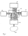
- the audiovisual presentation device shown in FIG. 1 comprises a screen 10, preferably in the form of a matrix display, such as a plasma or LCD display, one Drive unit 11 for moving the matrix display 10, a Control unit 12 for controlling the movement of the screen 10 via the drive unit 11 and an audio unit 13 for playback of sound information.
- Sound and image information as well Movement data are, preferably in digital format, in a memory 14 stored in data communication with the Control unit 12 stands as indicated by an arrow, the starts from the memory 14 and points to the control unit 12.
- the control unit 12 stands with the screen 10, the drive unit 11 and the audio unit 13, as indicated by arrows, in communication, partly in two-way communication, and all of these means of communication is shown schematically as the central communication unit 15 in FIG. 1 summarized.
- the control unit communication ports 12 are designated and form A, B, C, D, E, F, K Starting point or end point of the in Fig. 1 to designate the Communication used arrows.
- A is a communication line from the Control unit 12 to the audio unit 13, and this Communication line is used to transmit a warning signal from the control unit 12 to the audio unit 13.
- This warning signal is in the control unit 12 together with a fault signal generated, which starts from the screen 10 and over transmit the communication line K to the control unit 12 becomes.
- An audio signal is generated from the memory 14 by means of the control unit 12 via the communication line B to the audio unit 13 transferred.
- a non-stop actuation signal is generated by the control unit 12 to the drive unit 11 via the communication line C transfer.
- An action signal is sent from the control unit 12 via the communication line D transmitted to the drive unit 11.
- On The drive unit sends a reaction signal corresponding to this action 11 via the communication line E to the control unit 12 transferred.
- a video signal is sent over the communication line F from the control unit 12 (from the memory 14 originating) to the screen 10.
- Another communication line L exists starting from the drive unit 11 to the screen 10 and represents schematically represents the movement that the drive unit 11 on the Screen 10 transmits.
- the audiovisual presentation device shown schematically in FIG. 1 serves to move the screen 10 over the drive unit 11 as a function of that stored in the image memory Image information and vice versa for the transmission of the Screen movement via the drive unit 11 to the control unit 12 in this way to image and / or sound data or audio data to modify depending on the screen movement, For example, to break it down into segments and then again depending on the further course of movement of the screen 10 to put together into a coherent picture.
- the control unit 12 is in the form of a computer, preferably a personal computer that realizes the data storage 14 contains in the form of a hard disk drive.
- the data memory 14 On the output side is the data memory 14 with an intermediate unit connected, in the present case as a content player (data playback unit) 16 is designated.
- This content player 16 owns three outputs, the first one with a motion player, connected to a rotary player 17 in the present case is.
- the connection between the rotary player 17 and the content player 16 is a bidirectional connection.
- the second The output of the content player 16 is with a graphics card 18 connected and the third output of the content player 16 is connected to a sound card 19.
- the rotation player 17 has a bidirectional output on, which is connected to a preferably external controller 20 which in turn has an electric motor 21 on the output side the drive unit 11 is connected.
- the controller is preferred 20 as well as the motor 21 in the drive unit 11 integrated, the rest in drive connection with the screen 10 stands around this in the present embodiment to rotate a vertical axis passing through its center.
- Signals between the electric motor 21 and the screen 10 are, for example, via a rotary transformer or contactless transfer.
- the power supply for the screen 10 is also from a rotary transformer or the rotary transformer for signal transmission from the electric motor 21 to the Transfer screen 10. Appropriate image information arrives from the graphics card 18 to the screen 10.
- the output of the sound card 19 is with an external power amplifier or a power amplifier 22 connected on the output side drives a transducer 23.
- the final stage is preferred 22 integrated in the sound converter 23.
- the memory 14 contains rotation data relating to a rotation section 24 (in the general case a movement section) of the Content players 16 are supplied. Be similar Image data contained in the memory 14 an image section 25 of the Content players 16 supplied. Video data becomes a corresponding Video section 26 of the content player 16 supplied. In the image data and the video data which the image section 25 and the video section 26 of the content player 16 supplied are, it is image information, on the one hand Still picture information (25) and secondly moving picture information (26). Sound data contained in the memory 14 are Sound section 27 of the content player supplied. Image section data 25 and video section 26 are each the graphics card 18 and data from sound section 27 become the sound card 19 fed.
- Timeline data (clock data or Time synchronization data) stored that a timeline 28 are supplied in the content player 16 and for synchronization the data of the content player with each other and with the rotation player 17 or the external motor 21 and the screen 10 (its position) can be used, as explained in more detail below.
- Initialization signals are also sent from the memory via a Initialization signal line 29 the content player 16, the Rotation player 17 and the controller 20 fed.
- the rotation player 17 is connected to a limit value memory 30, the maximum values for those from the rotary player 17 to the Electric motor 21 via the controller 20 supplied rotation signals provides which maximum values always with the actual values of the rotation player 17 compared and possibly to blocking its output signals can be used to prevent unwanted Movement sequences or movement states of the screen 10 which is rotated by the motor 11 to prevent.
- the device according to the invention shown in FIG. 2 is in particular designed to dynamically adapt your hardware components synchronize. Because due to the objective, screen movement and image information for the screen in favor of one highly efficient advertising platform depending on each other control, a conventional distribution of image (and Sound) and control signals to the drive unit 11 is not enough, because the temporal playback behavior of some Factors depend on the hardware components, such as resolution (especially the screen), different data formats and the like, and because a time prediction has not been made can be. For this reason, a control loop implemented, the image content and the movement, present Rotation of the screen dynamically synchronized. This The control loop is, as can be seen from FIG. 2, bidirectional built up. That means it is constantly updated both the actual value of the Image content with the target value of the rotary movement and vice versa the actual value of the rotary movement with the nominal value of the Image content compared.
- Dynamics of synchronization in the present case means that the constant angular velocity (general speed of movement) acceleration is also freely definable and braking the screen rotation is possible.
- the control loop essentially consists of players 16 and 17 and the control unit 12 of FIG. 2.
- the players 16 and 17, which are preferably implemented as software, i.e. the content player and the rotation player communicate via a special software.
- the drive action, i.e. the angular velocity, the acceleration, braking and the Direction of rotation of the electric motor 21 and thus the screen 10 are transmitted from the rotation player to the motor control, and the reaction (the angular position) turns on at the same time reported back to the rotation player this way.
- the reaction the angular position
Landscapes
- Physics & Mathematics (AREA)
- General Physics & Mathematics (AREA)
- Engineering & Computer Science (AREA)
- Theoretical Computer Science (AREA)
- Controls And Circuits For Display Device (AREA)
- Stereophonic System (AREA)
- Electrically Operated Instructional Devices (AREA)
Abstract
Description
- 10
- Bildschirm
- 11
- Antriebseinheit
- 12
- Steuereinheit
- 13
- Audioeinheit
- 14
- Speicher
- 15
- Zentrale Kommunikationseinheit
- 16
- Content-Player
- 17
- Rotationsplayer
- 18
- Grafikkarte
- 19
- Soundkarte
- 20
- Controller
- 21
- Elektromotor
- 22
- Endstufe
- 23
- Schallwandler
- 24
- Rotationsabschnitt
- 25
- Bildabschnitt
- 26
- Videoabschnitt
- 27
- Tonabschnitt
- 28
- Timeline
- 29
- Initialisierungssignalleitung
Claims (15)
- Vorrichtung zur audiovisuellen Präsentation von Ton und Bild, insbesondere zu Werbezwecken, mit einem Speicher (14) und einem Bildschirm (10) zum Anzeigen von Bildinformation aus dem Speicher (14), gekennzeichnet durch eine Antriebseinheit (11) zum Bewegen des Bildschirms und eine Steuereinheit (12) zum Steuern der Bildschirmbewegung in Abhängigkeit der im Speicher (14) gespeicherten Bildinformation.
- Vorrichtung nach Anspruch 1, gekennzeichnet durch eine Regelschleife zum Synchronisieren der Bildschirmbewegung mit der Bildinformation.
- Vorrichtung nach Anspruch 2, dadurch gekennzeichnet, dass die Regelschleife für eine dynamische Synchronisation der Bildschirmbewegung mit der Bildinformation derart ausgelegt ist, dass neben einer gleichbleibenden Geschwindigkeit dieser Bewegung, deren Beschleunigen und Abbremsen frei definierbar sind.
- Vorrichtung nach Anspruch 2 oder 3, dadurch gekennzeichnet, dass die Regelschleife eine bidirektionelle Datenübertragung zwischen Bildschirm-Antriebseinheit (11) und Steuereinheit (12) unter ständigem Vergleich des Ist-Werts der Bildinformation mit dem Soll-Wert der Bildschirmbewegung und des Ist-Werts der Bildschirmbewegung mit dem Soll-Wert der Bildinformation vorsieht.
- Vorrichtung nach einem der Ansprüche 1 bis 4, dadurch gekennzeichnet, dass die Steuereinheit (12) dazu ausgelegt ist, die aus dem Speicher (14) gelesene Bildinformation in Abhängigkeit der Bildschirmbewegung zu modifizieren, vor allem zu zerlegen und neu zusammenzusetzen.
- Vorrichtung nach einem der Ansprüche 1 bis 5, dadurch gekennzeichnet, dass die Bildschirm-Antriebseinheit (11) einen Drehantrieb für den Bildschirm (10) umfasst, um diesen um eine senkrechte Achse, vor allem um das Bildschirmzentrum zu rotieren.
- Vorrichtung nach einem der Ansprüche 1 bis 5, dadurch gekennzeichnet, dass der Drehantrieb ein reibungsarmes Drehlager zur unbeschränkten Drehung des Bildschirms (10) umfasst.
- Vorrichtung nach Anspruch 7 oder 8, dadurch gekennzeichnet, dass die Antriebseinheit (11) einen Drehübertrager für die zwischen der Steuereinheit (12) und dem Bildschirm (10) übertragenen Signale bzw. Daten und/oder dessen Stromversorgung umfasst.
- Vorrichtung nach einem der Ansprüche 1 bis 7, gekennzeichnet durch eine kontaktfreie Signal- bzw. Datenübertragung zwischen Bildschirm (10) und Steuereinheit (12).
- Vorrichtung nach einem der Ansprüche 1 bis 8, dadurch gekennzeichnet, dass der Bildschirm (10) ein Matrixdisplay, vor allem ein Plasma- oder LCD-Display ist.
- Vorrichtung nach einem der Ansprüche 1 bis 8, dadurch gekennzeichnet, dass die Steuereinheit (12) einen Computer, vor allem einen Personal Computer, umfasst, und dass die Bild- und ggf. die Toninformation sowie Bild- und ggf. die Toninformation sowie Bewegungsdaten für den Bildschirmantrieb in einem Speicher (14) des Computers gespeichert sind.
- Vorrichtung nach Anspruch 11, dadurch gekennzeichnet, dass im Computer ein vom Inhalt des Speichers (14) beaufschlagten Content-Player (16) implementiert ist, der die im Speicher (14) des Computers gespeicherten Bild- und ggf. Tondaten sowie die Bewegungsdaten auf Grundlage von Timeline-Daten abspielt, die ebenfalls im Speicher (14) abgelegt sind.
- Vorrichtung nach Anspruch 12, dadurch gekennzeichnet, dass im Computer ein Bewegungsplayer (17) implementiert ist, der mit dem Ausgang des Content-Players (16) und der Bildschirm-Antriebseinheit (11) bidirektionell auf Grundlage eines gemeinsamen Auslösesignals für Speicher (14), Content-Player (16)und Bewegungsplayer (17) kommuniziert.
- Vorrichtung nach einem der Ansprüche 1 bis 13, dadurch gekennzeichnet, dass die Toninformation in die Steuerung des Bildschirmantriebs (11) einbezogen ist.
- Vorrichtung nach einem der Ansprüche 1 bis 14, dadurch gekennzeichnet, dass zwischen Antriebseinheit (11) und/oder Bildschirm (10) und Steuereinheit (12) Sicherheitsinformation, vor allem in Bezug auf maximale Geschwindigkeit, Beschleunigung und Sicherheitsabstand zur Umgebung ausgetauscht werden und ggf. die Antriebseinheit (11) still gesetzt wird.
Applications Claiming Priority (2)
| Application Number | Priority Date | Filing Date | Title |
|---|---|---|---|
| DE10313023 | 2003-03-24 | ||
| DE10313023A DE10313023B4 (de) | 2003-03-24 | 2003-03-24 | Vorrichtung zur audiovisuellen Präsentation von Ton und Bild |
Publications (3)
| Publication Number | Publication Date |
|---|---|
| EP1463018A2 true EP1463018A2 (de) | 2004-09-29 |
| EP1463018A3 EP1463018A3 (de) | 2004-12-15 |
| EP1463018B1 EP1463018B1 (de) | 2007-07-25 |
Family
ID=32798065
Family Applications (1)
| Application Number | Title | Priority Date | Filing Date |
|---|---|---|---|
| EP04006253A Expired - Lifetime EP1463018B1 (de) | 2003-03-24 | 2004-03-16 | Vorrichtung zur audiovisuellen Präsentation von Ton und Bild |
Country Status (8)
| Country | Link |
|---|---|
| US (1) | US7129963B2 (de) |
| EP (1) | EP1463018B1 (de) |
| JP (2) | JP5234555B2 (de) |
| CN (1) | CN1542712B (de) |
| AT (1) | ATE368273T1 (de) |
| DE (2) | DE10313023B4 (de) |
| DK (1) | DK1463018T3 (de) |
| ES (1) | ES2291763T3 (de) |
Cited By (3)
| Publication number | Priority date | Publication date | Assignee | Title |
|---|---|---|---|---|
| DE202010010562U1 (de) | 2010-07-23 | 2011-10-24 | GTG Gesellschaft für Technologie und Gestaltung mbH | Anzeigevorrichtung |
| CN104506917A (zh) * | 2014-12-26 | 2015-04-08 | 上海智物信息技术有限公司 | 显示屏的运动控制方法及其系统 |
| CN104506919A (zh) * | 2014-12-26 | 2015-04-08 | 上海智物信息技术有限公司 | 显示内容与显示屏运动的同步方法及其系统 |
Families Citing this family (5)
| Publication number | Priority date | Publication date | Assignee | Title |
|---|---|---|---|---|
| DE202006008325U1 (de) * | 2006-05-05 | 2006-08-10 | Stumm-Tippe, Karin | Vorrichtung zur Darstellung von Bildinformation |
| KR101055530B1 (ko) * | 2008-03-28 | 2011-08-08 | 삼성메디슨 주식회사 | 터치스크린 일체형 디스플레이부를 포함하는 초음파 시스템 |
| US20100295782A1 (en) | 2009-05-21 | 2010-11-25 | Yehuda Binder | System and method for control based on face ore hand gesture detection |
| CN104486683A (zh) * | 2014-12-26 | 2015-04-01 | 上海智物信息技术有限公司 | 视频编辑方法及其装置 |
| US10945706B2 (en) | 2017-05-05 | 2021-03-16 | Biim Ultrasound As | Hand held ultrasound probe |
Family Cites Families (21)
| Publication number | Priority date | Publication date | Assignee | Title |
|---|---|---|---|---|
| GB8718119D0 (en) * | 1987-07-30 | 1987-09-03 | Yuen Kwok Tung | Display device |
| JPH0820852B2 (ja) * | 1987-12-22 | 1996-03-04 | 株式会社タカラ | Led表示装置 |
| KR940007012Y1 (ko) * | 1991-01-31 | 1994-10-07 | 삼성전자 주식회사 | 영상표시기 회전장치 |
| JP3254314B2 (ja) * | 1993-10-01 | 2002-02-04 | 三菱電機株式会社 | 表示装置 |
| DE19642267A1 (de) * | 1995-10-11 | 1998-05-14 | Phat Chon Dipl Ing Chau | Mobilität eines Rechners |
| US5986634A (en) * | 1996-12-11 | 1999-11-16 | Silicon Light Machines | Display/monitor with orientation dependent rotatable image |
| US5973664A (en) * | 1998-03-19 | 1999-10-26 | Portrait Displays, Inc. | Parameterized image orientation for computer displays |
| JP3574751B2 (ja) * | 1998-10-30 | 2004-10-06 | 日本電信電話株式会社 | 三次元表示方法および装置 |
| KR100312486B1 (ko) * | 1998-11-13 | 2002-02-28 | 구자홍 | 영상표시기기의자동회전장치와그회전방법 |
| DE29910085U1 (de) * | 1999-06-10 | 1999-09-09 | Frenzel, Hans-Holger, 63743 Aschaffenburg | Interaktive Informationsstation mit Bildschirm, Eingabemöglichkeit und Stellvorrichtungen |
| DE19960544A1 (de) * | 1999-12-15 | 2001-07-26 | Infineon Technologies Ag | Steuerbares Objekt und System zum Steuern eines derartigen Objekts |
| JP3727516B2 (ja) * | 2000-07-13 | 2005-12-14 | 株式会社日立製作所 | 画像表示装置及びそれに用いる制御回路 |
| US6784855B2 (en) * | 2001-02-15 | 2004-08-31 | Microsoft Corporation | Methods and systems for a portable, interactive display device for use with a computer |
| US20020126110A1 (en) * | 2001-02-15 | 2002-09-12 | Julian Bowron | Flip display screen and methods of using same |
| US6931596B2 (en) * | 2001-03-05 | 2005-08-16 | Koninklijke Philips Electronics N.V. | Automatic positioning of display depending upon the viewer's location |
| JP2002311845A (ja) * | 2001-04-16 | 2002-10-25 | Fujitsu Ltd | 表示装置 |
| DE10206120A1 (de) * | 2002-02-14 | 2003-09-04 | Adsec Comp | Monitorsystemanordnung |
| US20030202003A1 (en) * | 2002-04-25 | 2003-10-30 | George Marmaropoulos | Method and apparatus for enhanced user interface display systems |
| US7542052B2 (en) * | 2002-05-31 | 2009-06-02 | Hewlett-Packard Development Company, L.P. | System and method of switching viewing orientations of a display |
| US7952569B2 (en) * | 2002-08-08 | 2011-05-31 | Hewlett-Packard Development Company, L.P. | System and method of switching between multiple viewing modes in a multi-head computer system |
| US6891920B1 (en) * | 2002-11-29 | 2005-05-10 | Fischer Imaging Corporation | Automated background processing mammographic image data |
-
2003
- 2003-03-24 DE DE10313023A patent/DE10313023B4/de not_active Expired - Fee Related
-
2004
- 2004-03-16 EP EP04006253A patent/EP1463018B1/de not_active Expired - Lifetime
- 2004-03-16 DK DK04006253T patent/DK1463018T3/da active
- 2004-03-16 DE DE502004004406T patent/DE502004004406D1/de not_active Expired - Lifetime
- 2004-03-16 AT AT04006253T patent/ATE368273T1/de active
- 2004-03-16 ES ES04006253T patent/ES2291763T3/es not_active Expired - Lifetime
- 2004-03-23 US US10/806,600 patent/US7129963B2/en not_active Expired - Fee Related
- 2004-03-24 JP JP2004086365A patent/JP5234555B2/ja not_active Expired - Fee Related
- 2004-03-24 CN CN2004100315582A patent/CN1542712B/zh not_active Expired - Fee Related
-
2011
- 2011-03-24 JP JP2011066355A patent/JP2011145700A/ja active Pending
Cited By (5)
| Publication number | Priority date | Publication date | Assignee | Title |
|---|---|---|---|---|
| DE202010010562U1 (de) | 2010-07-23 | 2011-10-24 | GTG Gesellschaft für Technologie und Gestaltung mbH | Anzeigevorrichtung |
| WO2012010328A1 (de) | 2010-07-23 | 2012-01-26 | Gtg Gmbh | Anzeigevorrichtung |
| CN103168323A (zh) * | 2010-07-23 | 2013-06-19 | Gtg有限责任公司 | 显示装置 |
| CN104506917A (zh) * | 2014-12-26 | 2015-04-08 | 上海智物信息技术有限公司 | 显示屏的运动控制方法及其系统 |
| CN104506919A (zh) * | 2014-12-26 | 2015-04-08 | 上海智物信息技术有限公司 | 显示内容与显示屏运动的同步方法及其系统 |
Also Published As
| Publication number | Publication date |
|---|---|
| DE10313023B4 (de) | 2006-02-23 |
| US7129963B2 (en) | 2006-10-31 |
| CN1542712B (zh) | 2012-07-04 |
| JP2011145700A (ja) | 2011-07-28 |
| EP1463018A3 (de) | 2004-12-15 |
| CN1542712A (zh) | 2004-11-03 |
| US20040189596A1 (en) | 2004-09-30 |
| DK1463018T3 (da) | 2007-11-26 |
| DE502004004406D1 (de) | 2007-09-06 |
| EP1463018B1 (de) | 2007-07-25 |
| ATE368273T1 (de) | 2007-08-15 |
| ES2291763T3 (es) | 2008-03-01 |
| JP5234555B2 (ja) | 2013-07-10 |
| JP2004287445A (ja) | 2004-10-14 |
| DE10313023A1 (de) | 2004-10-21 |
Similar Documents
| Publication | Publication Date | Title |
|---|---|---|
| DE60216286T2 (de) | Verbessertes fernsehen mit angepasstem inhalt | |
| CN102547248B (zh) | 多路实时监控单视频文件录制方法 | |
| DE69630579T2 (de) | Personalisierung einer interaktiven unterhaltung | |
| DE69611029T2 (de) | Informationsverarbeitung für interaktive Apparatur | |
| DE69931648T2 (de) | Kombiniertes werbe- und unterhaltungssystemnetzwerk | |
| DE69826258T2 (de) | Anzeigevorrichtung mit einem oder mehreren fenstern und platzierungsabhängiger kursor- und funktionskontrolle | |
| DE602005003471T2 (de) | Verfahren und system zur interaktiven steuerung von medien über ein netzwerk | |
| US20130071091A1 (en) | Hardware-Based, Client-Side, Video Compositing System | |
| EP1463018B1 (de) | Vorrichtung zur audiovisuellen Präsentation von Ton und Bild | |
| Sergi | A cry in the dark: the role of post-classical film sound | |
| DE102005038969A1 (de) | Unterhaltungssystem und tragbares Displaygerät hierfür | |
| DE102010028865A1 (de) | Holografisches Live-Präsentationssystem und Verfahren zur Liveübertragung einer holografischen Präsentation | |
| DE20314171U1 (de) | Vorrichtung zur audiovisuellen Präsentation von Ton und Bild | |
| US20070035665A1 (en) | Method and system for communicating lighting effects with additional layering in a video stream | |
| US5627952A (en) | Information displaying system which displays combined video and graphics images | |
| DE202007009526U1 (de) | Verkaufs- und/oder Präsentationssystem | |
| US20080013917A1 (en) | Information intermediation system | |
| DE102004028079A1 (de) | Festplattenaufzeichnungsgerät | |
| DE102005005094A1 (de) | Kombinierte analog-digitale Plakat- und Informationswand | |
| Williams et al. | Digital video for multimedia: considerations for capture, use and delivery | |
| EP1189443B1 (de) | Verfahren und Vorrichtung zur Steuerung von Interaktivität von Elementen einer Videosequenz | |
| GB2428830A (en) | Interactive multimedia system and interface | |
| DE102009031593A1 (de) | Verfahren und Vorrichtung zum Bereitstellen von Informationen | |
| DE112007000660T5 (de) | Verfahren zum Erweitern einer auf einem Medium enthaltenen Geschichte | |
| Bellard | Rapid learning instructional design programming: Applying multimedia and media effects principles |
Legal Events
| Date | Code | Title | Description |
|---|---|---|---|
| PUAI | Public reference made under article 153(3) epc to a published international application that has entered the european phase |
Free format text: ORIGINAL CODE: 0009012 |
|
| AK | Designated contracting states |
Kind code of ref document: A2 Designated state(s): AT BE BG CH CY CZ DE DK EE ES FI FR GB GR HU IE IT LI LU MC NL PL PT RO SE SI SK TR |
|
| AX | Request for extension of the european patent |
Extension state: AL LT LV MK |
|
| PUAL | Search report despatched |
Free format text: ORIGINAL CODE: 0009013 |
|
| AK | Designated contracting states |
Kind code of ref document: A3 Designated state(s): AT BE BG CH CY CZ DE DK EE ES FI FR GB GR HU IE IT LI LU MC NL PL PT RO SE SI SK TR |
|
| AX | Request for extension of the european patent |
Extension state: AL LT LV MK |
|
| 17P | Request for examination filed |
Effective date: 20050614 |
|
| AKX | Designation fees paid |
Designated state(s): AT BE BG CH CY CZ DE DK EE ES FI FR GB GR HU IE IT LI LU MC NL PL PT RO SE SI SK TR |
|
| AXX | Extension fees paid |
Extension state: LV Payment date: 20050614 |
|
| GRAP | Despatch of communication of intention to grant a patent |
Free format text: ORIGINAL CODE: EPIDOSNIGR1 |
|
| GRAS | Grant fee paid |
Free format text: ORIGINAL CODE: EPIDOSNIGR3 |
|
| GRAA | (expected) grant |
Free format text: ORIGINAL CODE: 0009210 |
|
| AK | Designated contracting states |
Kind code of ref document: B1 Designated state(s): AT BE BG CH CY CZ DE DK EE ES FI FR GB GR HU IE IT LI LU MC NL PL PT RO SE SI SK TR |
|
| AX | Request for extension of the european patent |
Extension state: LV |
|
| REG | Reference to a national code |
Ref country code: GB Ref legal event code: FG4D Free format text: NOT ENGLISH |
|
| REG | Reference to a national code |
Ref country code: CH Ref legal event code: EP |
|
| REG | Reference to a national code |
Ref country code: IE Ref legal event code: FG4D Free format text: LANGUAGE OF EP DOCUMENT: GERMAN |
|
| REF | Corresponds to: |
Ref document number: 502004004406 Country of ref document: DE Date of ref document: 20070906 Kind code of ref document: P |
|
| REG | Reference to a national code |
Ref country code: SE Ref legal event code: TRGR |
|
| REG | Reference to a national code |
Ref country code: DK Ref legal event code: T3 |
|
| GBT | Gb: translation of ep patent filed (gb section 77(6)(a)/1977) |
Effective date: 20071101 |
|
| REG | Reference to a national code |
Ref country code: CH Ref legal event code: NV Representative=s name: E. BLUM & CO. AG PATENT- UND MARKENANWAELTE VSP |
|
| PG25 | Lapsed in a contracting state [announced via postgrant information from national office to epo] |
Ref country code: BG Free format text: LAPSE BECAUSE OF FAILURE TO SUBMIT A TRANSLATION OF THE DESCRIPTION OR TO PAY THE FEE WITHIN THE PRESCRIBED TIME-LIMIT Effective date: 20071025 Ref country code: PT Free format text: LAPSE BECAUSE OF FAILURE TO SUBMIT A TRANSLATION OF THE DESCRIPTION OR TO PAY THE FEE WITHIN THE PRESCRIBED TIME-LIMIT Effective date: 20071226 |
|
| ET | Fr: translation filed | ||
| PG25 | Lapsed in a contracting state [announced via postgrant information from national office to epo] |
Ref country code: PL Free format text: LAPSE BECAUSE OF FAILURE TO SUBMIT A TRANSLATION OF THE DESCRIPTION OR TO PAY THE FEE WITHIN THE PRESCRIBED TIME-LIMIT Effective date: 20070725 |
|
| REG | Reference to a national code |
Ref country code: ES Ref legal event code: FG2A Ref document number: 2291763 Country of ref document: ES Kind code of ref document: T3 |
|
| REG | Reference to a national code |
Ref country code: IE Ref legal event code: FD4D |
|
| PG25 | Lapsed in a contracting state [announced via postgrant information from national office to epo] |
Ref country code: GR Free format text: LAPSE BECAUSE OF FAILURE TO SUBMIT A TRANSLATION OF THE DESCRIPTION OR TO PAY THE FEE WITHIN THE PRESCRIBED TIME-LIMIT Effective date: 20071026 |
|
| PG25 | Lapsed in a contracting state [announced via postgrant information from national office to epo] |
Ref country code: IE Free format text: LAPSE BECAUSE OF FAILURE TO SUBMIT A TRANSLATION OF THE DESCRIPTION OR TO PAY THE FEE WITHIN THE PRESCRIBED TIME-LIMIT Effective date: 20070725 Ref country code: SK Free format text: LAPSE BECAUSE OF FAILURE TO SUBMIT A TRANSLATION OF THE DESCRIPTION OR TO PAY THE FEE WITHIN THE PRESCRIBED TIME-LIMIT Effective date: 20070725 |
|
| PLBE | No opposition filed within time limit |
Free format text: ORIGINAL CODE: 0009261 |
|
| STAA | Information on the status of an ep patent application or granted ep patent |
Free format text: STATUS: NO OPPOSITION FILED WITHIN TIME LIMIT |
|
| PG25 | Lapsed in a contracting state [announced via postgrant information from national office to epo] |
Ref country code: RO Free format text: LAPSE BECAUSE OF FAILURE TO SUBMIT A TRANSLATION OF THE DESCRIPTION OR TO PAY THE FEE WITHIN THE PRESCRIBED TIME-LIMIT Effective date: 20070725 |
|
| 26N | No opposition filed |
Effective date: 20080428 |
|
| PG25 | Lapsed in a contracting state [announced via postgrant information from national office to epo] |
Ref country code: MC Free format text: LAPSE BECAUSE OF NON-PAYMENT OF DUE FEES Effective date: 20080331 |
|
| PG25 | Lapsed in a contracting state [announced via postgrant information from national office to epo] |
Ref country code: EE Free format text: LAPSE BECAUSE OF FAILURE TO SUBMIT A TRANSLATION OF THE DESCRIPTION OR TO PAY THE FEE WITHIN THE PRESCRIBED TIME-LIMIT Effective date: 20070725 |
|
| PG25 | Lapsed in a contracting state [announced via postgrant information from national office to epo] |
Ref country code: SI Free format text: LAPSE BECAUSE OF FAILURE TO SUBMIT A TRANSLATION OF THE DESCRIPTION OR TO PAY THE FEE WITHIN THE PRESCRIBED TIME-LIMIT Effective date: 20070725 |
|
| PG25 | Lapsed in a contracting state [announced via postgrant information from national office to epo] |
Ref country code: CY Free format text: LAPSE BECAUSE OF FAILURE TO SUBMIT A TRANSLATION OF THE DESCRIPTION OR TO PAY THE FEE WITHIN THE PRESCRIBED TIME-LIMIT Effective date: 20070725 |
|
| PGFP | Annual fee paid to national office [announced via postgrant information from national office to epo] |
Ref country code: BE Payment date: 20090330 Year of fee payment: 6 |
|
| PG25 | Lapsed in a contracting state [announced via postgrant information from national office to epo] |
Ref country code: HU Free format text: LAPSE BECAUSE OF FAILURE TO SUBMIT A TRANSLATION OF THE DESCRIPTION OR TO PAY THE FEE WITHIN THE PRESCRIBED TIME-LIMIT Effective date: 20080126 Ref country code: LU Free format text: LAPSE BECAUSE OF NON-PAYMENT OF DUE FEES Effective date: 20080316 |
|
| BERE | Be: lapsed |
Owner name: GTG G.- FUR ELEKTRONISCHE GERATE MBH Effective date: 20100331 |
|
| PG25 | Lapsed in a contracting state [announced via postgrant information from national office to epo] |
Ref country code: BE Free format text: LAPSE BECAUSE OF NON-PAYMENT OF DUE FEES Effective date: 20100331 |
|
| PG25 | Lapsed in a contracting state [announced via postgrant information from national office to epo] |
Ref country code: IT Free format text: LAPSE BECAUSE OF NON-PAYMENT OF DUE FEES Effective date: 20100316 |
|
| REG | Reference to a national code |
Ref country code: DE Ref legal event code: R082 Ref document number: 502004004406 Country of ref document: DE Representative=s name: HEISSE KURSAWE EVERSHEDS RECHTSANWAELTE PATENT, DE |
|
| REG | Reference to a national code |
Ref country code: CH Ref legal event code: PFA Owner name: GTG GMBH, DE Free format text: FORMER OWNER: GTG GESELLSCHAFT FUER ELEKTRONISCHE GERAETE MBH, DE |
|
| REG | Reference to a national code |
Ref country code: DE Ref legal event code: R082 Ref document number: 502004004406 Country of ref document: DE Representative=s name: HEISSE KURSAWE EVERSHEDS RECHTSANWAELTE PATENT, DE |
|
| PGFP | Annual fee paid to national office [announced via postgrant information from national office to epo] |
Ref country code: CZ Payment date: 20130220 Year of fee payment: 10 Ref country code: CH Payment date: 20130322 Year of fee payment: 10 Ref country code: FI Payment date: 20130313 Year of fee payment: 10 Ref country code: DK Payment date: 20130320 Year of fee payment: 10 |
|
| REG | Reference to a national code |
Ref country code: DE Ref legal event code: R082 Ref document number: 502004004406 Country of ref document: DE Representative=s name: HEISSE KURSAWE EVERSHEDS RECHTSANWAELTE PATENT, DE Effective date: 20130319 Ref country code: DE Ref legal event code: R081 Ref document number: 502004004406 Country of ref document: DE Owner name: GTG GMBH, DE Free format text: FORMER OWNER: GTG GESELLSCHAFT FUER TECHNOLOGIE UND GESTALTUNG MBH, 82152 PLANEGG, DE Effective date: 20130319 Ref country code: DE Ref legal event code: R082 Ref document number: 502004004406 Country of ref document: DE Representative=s name: HEISSE KURSAWE EVERSHEDS RECHTSANWAELTE PATENT, DE Effective date: 20120416 |
|
| REG | Reference to a national code |
Ref country code: ES Ref legal event code: PC2A Owner name: GTG GMBH Effective date: 20130506 |
|
| PGFP | Annual fee paid to national office [announced via postgrant information from national office to epo] |
Ref country code: NL Payment date: 20130320 Year of fee payment: 10 |
|
| REG | Reference to a national code |
Ref country code: AT Ref legal event code: HC Ref document number: 368273 Country of ref document: AT Kind code of ref document: T Owner name: GTG GMBH, DE Effective date: 20130506 |
|
| REG | Reference to a national code |
Ref country code: NL Ref legal event code: TD Effective date: 20130607 |
|
| REG | Reference to a national code |
Ref country code: FR Ref legal event code: CD Owner name: GTG GMBH Effective date: 20130605 Ref country code: FR Ref legal event code: CJ Effective date: 20130605 |
|
| REG | Reference to a national code |
Ref country code: DK Ref legal event code: EBP Effective date: 20140331 |
|
| REG | Reference to a national code |
Ref country code: NL Ref legal event code: V1 Effective date: 20141001 |
|
| PG25 | Lapsed in a contracting state [announced via postgrant information from national office to epo] |
Ref country code: FI Free format text: LAPSE BECAUSE OF NON-PAYMENT OF DUE FEES Effective date: 20140316 Ref country code: CZ Free format text: LAPSE BECAUSE OF NON-PAYMENT OF DUE FEES Effective date: 20140316 |
|
| REG | Reference to a national code |
Ref country code: CH Ref legal event code: PL |
|
| PG25 | Lapsed in a contracting state [announced via postgrant information from national office to epo] |
Ref country code: CH Free format text: LAPSE BECAUSE OF NON-PAYMENT OF DUE FEES Effective date: 20140331 Ref country code: LI Free format text: LAPSE BECAUSE OF NON-PAYMENT OF DUE FEES Effective date: 20140331 |
|
| PG25 | Lapsed in a contracting state [announced via postgrant information from national office to epo] |
Ref country code: NL Free format text: LAPSE BECAUSE OF NON-PAYMENT OF DUE FEES Effective date: 20141001 |
|
| REG | Reference to a national code |
Ref country code: FR Ref legal event code: PLFP Year of fee payment: 12 |
|
| PG25 | Lapsed in a contracting state [announced via postgrant information from national office to epo] |
Ref country code: DK Free format text: LAPSE BECAUSE OF NON-PAYMENT OF DUE FEES Effective date: 20140331 |
|
| PGFP | Annual fee paid to national office [announced via postgrant information from national office to epo] |
Ref country code: AT Payment date: 20150401 Year of fee payment: 12 Ref country code: SE Payment date: 20150330 Year of fee payment: 12 |
|
| PGFP | Annual fee paid to national office [announced via postgrant information from national office to epo] |
Ref country code: DE Payment date: 20150410 Year of fee payment: 12 Ref country code: ES Payment date: 20150427 Year of fee payment: 12 Ref country code: GB Payment date: 20150420 Year of fee payment: 12 |
|
| PGFP | Annual fee paid to national office [announced via postgrant information from national office to epo] |
Ref country code: IT Payment date: 20150331 Year of fee payment: 12 Ref country code: FR Payment date: 20150330 Year of fee payment: 12 |
|
| REG | Reference to a national code |
Ref country code: DE Ref legal event code: R119 Ref document number: 502004004406 Country of ref document: DE |
|
| REG | Reference to a national code |
Ref country code: SE Ref legal event code: EUG |
|
| REG | Reference to a national code |
Ref country code: AT Ref legal event code: MM01 Ref document number: 368273 Country of ref document: AT Kind code of ref document: T Effective date: 20160316 |
|
| GBPC | Gb: european patent ceased through non-payment of renewal fee |
Effective date: 20160316 |
|
| PG25 | Lapsed in a contracting state [announced via postgrant information from national office to epo] |
Ref country code: SE Free format text: LAPSE BECAUSE OF NON-PAYMENT OF DUE FEES Effective date: 20160317 |
|
| REG | Reference to a national code |
Ref country code: FR Ref legal event code: ST Effective date: 20161130 |
|
| PG25 | Lapsed in a contracting state [announced via postgrant information from national office to epo] |
Ref country code: GB Free format text: LAPSE BECAUSE OF NON-PAYMENT OF DUE FEES Effective date: 20160316 Ref country code: DE Free format text: LAPSE BECAUSE OF NON-PAYMENT OF DUE FEES Effective date: 20161001 Ref country code: FR Free format text: LAPSE BECAUSE OF NON-PAYMENT OF DUE FEES Effective date: 20160331 |
|
| PG25 | Lapsed in a contracting state [announced via postgrant information from national office to epo] |
Ref country code: IT Free format text: LAPSE BECAUSE OF NON-PAYMENT OF DUE FEES Effective date: 20160316 Ref country code: AT Free format text: LAPSE BECAUSE OF NON-PAYMENT OF DUE FEES Effective date: 20160316 |
|
| REG | Reference to a national code |
Ref country code: ES Ref legal event code: FD2A Effective date: 20170427 |
|
| PGFP | Annual fee paid to national office [announced via postgrant information from national office to epo] |
Ref country code: TR Payment date: 20170316 Year of fee payment: 14 |
|
| PG25 | Lapsed in a contracting state [announced via postgrant information from national office to epo] |
Ref country code: ES Free format text: LAPSE BECAUSE OF NON-PAYMENT OF DUE FEES Effective date: 20160317 |
|
| PG25 | Lapsed in a contracting state [announced via postgrant information from national office to epo] |
Ref country code: TR Free format text: LAPSE BECAUSE OF NON-PAYMENT OF DUE FEES Effective date: 20180316 |