EP1460413B1 - Procédé et dispositif de mesure in vitro ou in vivo de la concentration d'un composant - Google Patents
Procédé et dispositif de mesure in vitro ou in vivo de la concentration d'un composant Download PDFInfo
- Publication number
- EP1460413B1 EP1460413B1 EP20040251518 EP04251518A EP1460413B1 EP 1460413 B1 EP1460413 B1 EP 1460413B1 EP 20040251518 EP20040251518 EP 20040251518 EP 04251518 A EP04251518 A EP 04251518A EP 1460413 B1 EP1460413 B1 EP 1460413B1
- Authority
- EP
- European Patent Office
- Prior art keywords
- order
- positive
- subject
- negative
- intensity
- Prior art date
- Legal status (The legal status is an assumption and is not a legal conclusion. Google has not performed a legal analysis and makes no representation as to the accuracy of the status listed.)
- Expired - Lifetime
Links
- 238000000034 method Methods 0.000 title claims description 30
- 238000000338 in vitro Methods 0.000 title description 2
- 238000012623 in vivo measurement Methods 0.000 title 1
- 238000002835 absorbance Methods 0.000 claims description 15
- 239000000306 component Substances 0.000 description 36
- WQZGKKKJIJFFOK-GASJEMHNSA-N Glucose Natural products OC[C@H]1OC(O)[C@H](O)[C@@H](O)[C@@H]1O WQZGKKKJIJFFOK-GASJEMHNSA-N 0.000 description 23
- 239000008103 glucose Substances 0.000 description 23
- 238000005259 measurement Methods 0.000 description 18
- 210000004369 blood Anatomy 0.000 description 17
- 239000008280 blood Substances 0.000 description 17
- 210000001124 body fluid Anatomy 0.000 description 11
- 230000036541 health Effects 0.000 description 5
- 210000001519 tissue Anatomy 0.000 description 5
- 238000000862 absorption spectrum Methods 0.000 description 4
- 239000012503 blood component Substances 0.000 description 4
- HVYWMOMLDIMFJA-DPAQBDIFSA-N cholesterol Chemical compound C1C=C2C[C@@H](O)CC[C@]2(C)[C@@H]2[C@@H]1[C@@H]1CC[C@H]([C@H](C)CCCC(C)C)[C@@]1(C)CC2 HVYWMOMLDIMFJA-DPAQBDIFSA-N 0.000 description 4
- NOESYZHRGYRDHS-UHFFFAOYSA-N insulin Chemical compound N1C(=O)C(NC(=O)C(CCC(N)=O)NC(=O)C(CCC(O)=O)NC(=O)C(C(C)C)NC(=O)C(NC(=O)CN)C(C)CC)CSSCC(C(NC(CO)C(=O)NC(CC(C)C)C(=O)NC(CC=2C=CC(O)=CC=2)C(=O)NC(CCC(N)=O)C(=O)NC(CC(C)C)C(=O)NC(CCC(O)=O)C(=O)NC(CC(N)=O)C(=O)NC(CC=2C=CC(O)=CC=2)C(=O)NC(CSSCC(NC(=O)C(C(C)C)NC(=O)C(CC(C)C)NC(=O)C(CC=2C=CC(O)=CC=2)NC(=O)C(CC(C)C)NC(=O)C(C)NC(=O)C(CCC(O)=O)NC(=O)C(C(C)C)NC(=O)C(CC(C)C)NC(=O)C(CC=2NC=NC=2)NC(=O)C(CO)NC(=O)CNC2=O)C(=O)NCC(=O)NC(CCC(O)=O)C(=O)NC(CCCNC(N)=N)C(=O)NCC(=O)NC(CC=3C=CC=CC=3)C(=O)NC(CC=3C=CC=CC=3)C(=O)NC(CC=3C=CC(O)=CC=3)C(=O)NC(C(C)O)C(=O)N3C(CCC3)C(=O)NC(CCCCN)C(=O)NC(C)C(O)=O)C(=O)NC(CC(N)=O)C(O)=O)=O)NC(=O)C(C(C)CC)NC(=O)C(CO)NC(=O)C(C(C)O)NC(=O)C1CSSCC2NC(=O)C(CC(C)C)NC(=O)C(NC(=O)C(CCC(N)=O)NC(=O)C(CC(N)=O)NC(=O)C(NC(=O)C(N)CC=1C=CC=CC=1)C(C)C)CC1=CN=CN1 NOESYZHRGYRDHS-UHFFFAOYSA-N 0.000 description 4
- 230000003287 optical effect Effects 0.000 description 4
- 238000001228 spectrum Methods 0.000 description 4
- 238000010521 absorption reaction Methods 0.000 description 3
- 239000003153 chemical reaction reagent Substances 0.000 description 3
- 201000010099 disease Diseases 0.000 description 3
- 208000037265 diseases, disorders, signs and symptoms Diseases 0.000 description 3
- 235000012054 meals Nutrition 0.000 description 3
- 102000009027 Albumins Human genes 0.000 description 2
- 108010088751 Albumins Proteins 0.000 description 2
- BPYKTIZUTYGOLE-IFADSCNNSA-N Bilirubin Chemical compound N1C(=O)C(C)=C(C=C)\C1=C\C1=C(C)C(CCC(O)=O)=C(CC2=C(C(C)=C(\C=C/3C(=C(C=C)C(=O)N\3)C)N2)CCC(O)=O)N1 BPYKTIZUTYGOLE-IFADSCNNSA-N 0.000 description 2
- 229910000530 Gallium indium arsenide Inorganic materials 0.000 description 2
- 102000001554 Hemoglobins Human genes 0.000 description 2
- 108010054147 Hemoglobins Proteins 0.000 description 2
- 102000004877 Insulin Human genes 0.000 description 2
- 108090001061 Insulin Proteins 0.000 description 2
- 241001465754 Metazoa Species 0.000 description 2
- XAGFODPZIPBFFR-UHFFFAOYSA-N aluminium Chemical compound [Al] XAGFODPZIPBFFR-UHFFFAOYSA-N 0.000 description 2
- 229910052782 aluminium Inorganic materials 0.000 description 2
- 230000008859 change Effects 0.000 description 2
- 235000012000 cholesterol Nutrition 0.000 description 2
- DDRJAANPRJIHGJ-UHFFFAOYSA-N creatinine Chemical compound CN1CC(=O)NC1=N DDRJAANPRJIHGJ-UHFFFAOYSA-N 0.000 description 2
- 239000013078 crystal Substances 0.000 description 2
- 238000010586 diagram Methods 0.000 description 2
- 230000000694 effects Effects 0.000 description 2
- 239000011521 glass Substances 0.000 description 2
- 229910052736 halogen Inorganic materials 0.000 description 2
- 150000002367 halogens Chemical class 0.000 description 2
- WPYVAWXEWQSOGY-UHFFFAOYSA-N indium antimonide Chemical compound [Sb]#[In] WPYVAWXEWQSOGY-UHFFFAOYSA-N 0.000 description 2
- 229940125396 insulin Drugs 0.000 description 2
- 210000000496 pancreas Anatomy 0.000 description 2
- 238000010238 partial least squares regression Methods 0.000 description 2
- 230000035699 permeability Effects 0.000 description 2
- 238000012545 processing Methods 0.000 description 2
- 102000004169 proteins and genes Human genes 0.000 description 2
- 108090000623 proteins and genes Proteins 0.000 description 2
- 238000004611 spectroscopical analysis Methods 0.000 description 2
- 239000000126 substance Substances 0.000 description 2
- 238000012360 testing method Methods 0.000 description 2
- 210000002700 urine Anatomy 0.000 description 2
- XLYOFNOQVPJJNP-UHFFFAOYSA-N water Substances O XLYOFNOQVPJJNP-UHFFFAOYSA-N 0.000 description 2
- 206010003210 Arteriosclerosis Diseases 0.000 description 1
- 208000002177 Cataract Diseases 0.000 description 1
- 206010011878 Deafness Diseases 0.000 description 1
- 206010020772 Hypertension Diseases 0.000 description 1
- 208000028389 Nerve injury Diseases 0.000 description 1
- 208000037111 Retinal Hemorrhage Diseases 0.000 description 1
- XSQUKJJJFZCRTK-UHFFFAOYSA-N Urea Chemical compound NC(N)=O XSQUKJJJFZCRTK-UHFFFAOYSA-N 0.000 description 1
- 206010047571 Visual impairment Diseases 0.000 description 1
- 238000004458 analytical method Methods 0.000 description 1
- 238000013459 approach Methods 0.000 description 1
- 208000011775 arteriosclerosis disease Diseases 0.000 description 1
- 239000004202 carbamide Substances 0.000 description 1
- 238000011109 contamination Methods 0.000 description 1
- 229940109239 creatinine Drugs 0.000 description 1
- 238000013500 data storage Methods 0.000 description 1
- 238000011161 development Methods 0.000 description 1
- 206010012601 diabetes mellitus Diseases 0.000 description 1
- 238000009792 diffusion process Methods 0.000 description 1
- 230000009977 dual effect Effects 0.000 description 1
- 210000000624 ear auricle Anatomy 0.000 description 1
- 230000007613 environmental effect Effects 0.000 description 1
- 210000003722 extracellular fluid Anatomy 0.000 description 1
- 230000010370 hearing loss Effects 0.000 description 1
- 231100000888 hearing loss Toxicity 0.000 description 1
- 208000016354 hearing loss disease Diseases 0.000 description 1
- 238000001727 in vivo Methods 0.000 description 1
- 208000015181 infectious disease Diseases 0.000 description 1
- 230000031700 light absorption Effects 0.000 description 1
- 210000004185 liver Anatomy 0.000 description 1
- 210000005229 liver cell Anatomy 0.000 description 1
- 239000000463 material Substances 0.000 description 1
- 239000000203 mixture Substances 0.000 description 1
- 238000012544 monitoring process Methods 0.000 description 1
- 230000008764 nerve damage Effects 0.000 description 1
- 230000008569 process Effects 0.000 description 1
- 230000005855 radiation Effects 0.000 description 1
- 210000003296 saliva Anatomy 0.000 description 1
- 230000035939 shock Effects 0.000 description 1
- 210000002363 skeletal muscle cell Anatomy 0.000 description 1
- 238000007619 statistical method Methods 0.000 description 1
- 210000004243 sweat Anatomy 0.000 description 1
- 208000029257 vision disease Diseases 0.000 description 1
- 230000004393 visual impairment Effects 0.000 description 1
Images


Classifications
-
- G—PHYSICS
- G01—MEASURING; TESTING
- G01N—INVESTIGATING OR ANALYSING MATERIALS BY DETERMINING THEIR CHEMICAL OR PHYSICAL PROPERTIES
- G01N21/00—Investigating or analysing materials by the use of optical means, i.e. using sub-millimetre waves, infrared, visible or ultraviolet light
- G01N21/62—Systems in which the material investigated is excited whereby it emits light or causes a change in wavelength of the incident light
-
- A—HUMAN NECESSITIES
- A61—MEDICAL OR VETERINARY SCIENCE; HYGIENE
- A61B—DIAGNOSIS; SURGERY; IDENTIFICATION
- A61B5/00—Measuring for diagnostic purposes; Identification of persons
- A61B5/145—Measuring characteristics of blood in vivo, e.g. gas concentration, pH value; Measuring characteristics of body fluids or tissues, e.g. interstitial fluid, cerebral tissue
- A61B5/1455—Measuring characteristics of blood in vivo, e.g. gas concentration, pH value; Measuring characteristics of body fluids or tissues, e.g. interstitial fluid, cerebral tissue using optical sensors, e.g. spectral photometrical oximeters
-
- A—HUMAN NECESSITIES
- A61—MEDICAL OR VETERINARY SCIENCE; HYGIENE
- A61B—DIAGNOSIS; SURGERY; IDENTIFICATION
- A61B5/00—Measuring for diagnostic purposes; Identification of persons
- A61B5/145—Measuring characteristics of blood in vivo, e.g. gas concentration, pH value; Measuring characteristics of body fluids or tissues, e.g. interstitial fluid, cerebral tissue
- A61B5/14532—Measuring characteristics of blood in vivo, e.g. gas concentration, pH value; Measuring characteristics of body fluids or tissues, e.g. interstitial fluid, cerebral tissue for measuring glucose, e.g. by tissue impedance measurement
-
- G—PHYSICS
- G01—MEASURING; TESTING
- G01J—MEASUREMENT OF INTENSITY, VELOCITY, SPECTRAL CONTENT, POLARISATION, PHASE OR PULSE CHARACTERISTICS OF INFRARED, VISIBLE OR ULTRAVIOLET LIGHT; COLORIMETRY; RADIATION PYROMETRY
- G01J3/00—Spectrometry; Spectrophotometry; Monochromators; Measuring colours
- G01J3/12—Generating the spectrum; Monochromators
- G01J3/1256—Generating the spectrum; Monochromators using acousto-optic tunable filter
-
- G—PHYSICS
- G01—MEASURING; TESTING
- G01N—INVESTIGATING OR ANALYSING MATERIALS BY DETERMINING THEIR CHEMICAL OR PHYSICAL PROPERTIES
- G01N21/00—Investigating or analysing materials by the use of optical means, i.e. using sub-millimetre waves, infrared, visible or ultraviolet light
- G01N21/17—Systems in which incident light is modified in accordance with the properties of the material investigated
- G01N21/25—Colour; Spectral properties, i.e. comparison of effect of material on the light at two or more different wavelengths or wavelength bands
- G01N21/31—Investigating relative effect of material at wavelengths characteristic of specific elements or molecules, e.g. atomic absorption spectrometry
Definitions
- the present invention relates to a measurement of a concentration of a component in a subject. More particularly, the present invention relates to a method and apparatus for accurately measuring a concentration of a component in a subject, such as a bodily fluid in a human body, by removing a time difference between a measurement of a reference light and a measurement of a signal light.
- bodily fluid is organically circulated and adjusted so that an amount of bodily fluid is maintained within a predetermined range.
- Bodily fluids include blood, urine, interstitial fluid, sweat, and saliva.
- concentrations of blood and urine are essential parameters in determining a person's state of health.
- concentrations of blood components such as glucose, hemoglobin, bilirubin, cholesterol, albumin, creatinine, protein, and urea, play an important role in assessing a person's state of health
- a composition or a volume of a component in a bodily fluid changes, which may result in death.
- a normal person's blood glucose concentration is about 80 mg/dl before a meal and about 120 mg/dl after a meal.
- a human pancreas secretes an appropriate amount of insulin before or after the meal so that glucose can be absorbed into the liver and skeletal muscle cells.
- pancreas does not secrete an appropriate amount of insulin to maintain a normal blood glucose concentration due to a disease or other causes, an excessive amount of glucose exists in the blood, which causes diseases of the heart or liver, arteriosclerosis, hypertension, cataract, retinal bleeding, nerve damage, hearing loss, or visual impairment, all of which may cause serious problems including death. Accordingly, a technique of measuring a change in a bodily fluid in a human body is considered very important.
- Methods of measuring the concentration of a component of bodily fluid include invasive methods of directly collecting a sample from a subject and gathering measurements on the collected part of the subject and noninvasive methods of gathering measurements without directly collecting a sample from a subject. Since invasive methods have many problems, techniques of easily analyzing components of bodily fluid using a noninvasive method have been continuously researched and developed. Conventionally, when measuring a component of bodily fluid, for example, blood glucose, blood is extracted, reacted with a reagent, and then analyzed by using a clinical analysis system or quantifying a change in the color of a test strip. When such a blood glucose test is performed daily, a patient suffers from pain resulting from the direct blood collection and is susceptible to infection.
- spectroscopic methods of measuring the concentration of a blood component in a human body In most conventional, spectroscopic methods of measuring the concentration of a blood component in a human body, light within a visible ray and near infrared ray (NIR) wavelength range is radiated onto a part of the human body, and then, light reflected from or transmitted through the human body is detected. In such spectroscopic methods, a spectrum is usually measured to measure the concentration of a blood component.
- a reference light source having a wavelength that responds best to a blood component to be measured and a bandwidth that effectively counterbalances an influence of an interference substance is required.
- a continuous wave (CW) lamp is used as a light source, and the intensity of the light is measured using an expensive array detector, or a spectrum is measured using a spectroscopic system, in order to calculate the concentration of a component.
- a light emitting diode (LED) or a laser diode (LD) may be used as the light source.
- the concentration of a component to be measured may be very low in blood and a light diffusion effect is greater than a light absorption effect in living tissue and blood, detected signals are very weak. Thus, a method of amplifying the signal is required. Moreover, since organic substances in a human body continuously flow, a component concentration can be accurately measured only when the measurement is quickly performed. In addition, it must be noted that an average energy radiated onto a human body should not go beyond a limit that may damage the human body. In particular, in an NIR wavelength range of 700 through 2500 nm, a glucose absorption band is widely distributed, but a maximum absorption of glucose is small as compared to a large aqueous background spectrum. Resultantly, a signal to noise ratio (SNR) is small, which makes accurate measurements very difficult.
- SNR signal to noise ratio
- absorbance is measured, and a multivariate statistical analysis is performed on the absorbance to analyze a component concentration.
- the absorbance can be expressed as a negative log ratio between signal light intensity measured from a sample and reference light intensity. Since the reference light intensity measured without a human body and the signal light intensity measured from the human body are measured at predetermined time intervals, a time difference exists between the measurement of the signal light intensity and the measurement of the reference light intensity. Such a time difference can be removed by simultaneously measuring the reference light intensity and the signal light intensity. In a conventional approach for removing the time difference, a beam is split into two beams by a beam splitter before being radiated onto a human body.
- One of the two beams is sent to a reference light intensity channel, and the other is sent to a signal light intensity channel. Intensities of these two beams are separately measured and used to predict the concentration of a particular component. In this situation, however, an additional optical system for splitting an input beam and related parts are required. Therefore, it is difficult to construct a compact system. Meanwhile, when a beam splitter is not used, the reference light intensity is measured first, then the signal light intensity is measured in order to calculate absorbance. However, due to influences of various changes occurring during an interval of time between the measurement of the reference light intensity and the measurement of the signal light intensity, it is difficult to accurately predict the concentration of a component.
- US 5,039,855 describes a dual beam acoustic-optic tunable spectrometer which generates two beams from an acoustic-optic filter, one beam being used to measure a sample and the other as a reference, using two detectors.
- the apparatus may further include a condenser lens on an optical path between the light source and the tunable filter to condense the light emitted from the light source.
- the light source may be a halogen lamp.
- the first and second light detectors may be photodetectors made of a material selected from the group consisting of InGaAs, PbS, and InSb.
- the tunable filter may include a transducer and an acoustic-optic medium and the acoustic-optic medium may be a crystal.
- the apparatus may further include a beam guiding unit that guides the positive-order beam generated by the tunable filter to be transmitted to be parallel to the subject and guides the negative-order beam generated by the tunable filter to be transmitted to be parallel to the reference matter.
- the first and second beam guiding units may be selected from the group consisting of a tapered aluminum tube, a glass rod, and a hollow waveguide.
- the apparatus may further include a refractive index matching unit, which is disposed between the beam guiding unit and the subject, to match an internal refractive index of the subject with an external refractive index of the subject.
- a refractive index matching unit which is disposed between the beam guiding unit and the subject, to match an internal refractive index of the subject with an external refractive index of the subject.
- the signal processor may obtain the intensity relationship equation using a positive-order beam and a negative-order beam, which are output from the reference matter when a positive-order beam and a negative-order beam generated by the tunable filter at a particular wavelength are radiated onto the reference matter.
- setting the intensity relationship equation may include generating the positive-order and negative-order beams having the second wavelength band from the light, which has the first wavelength band and is provided from a light source, according to a radio frequency (RF) signal having a predetermined frequency, radiating the positive-order and negative-order beams onto the reference matter and detecting the intensities of the respective positive-order and negative-order beams output from the reference matter, and setting the intensity relationship equation based on the detected intensities of the positive-order and negative-order beams.
- RF radio frequency
- applying the light having the first wavelength band and detecting the intensities of the positive-order beam output from the subject and the negative-order beam output from the reference matter may include generating the positive-order and negative-order beams having the second wavelength band from the light, which has the first wavelength band and is provided from the light source, according to a radio frequency (RF) signal having a predetermined frequency and radiating the generated positive-order and negative-order beams onto the subject and the reference matter, respectively, and detecting the intensity of the positive-order beam output from the subject and the intensity of the negative-order beam output from the reference matter.
- RF radio frequency
- a computer readable recording medium having recorded therein a program for executing the above method.
- FIG. 1 is a block diagram of an apparatus for measuring a concentration of a component in a subject according to an embodiment of the present invention.
- the apparatus includes a light source 111, a condenser lens 112, a radio frequency (RF) signal generator 113, a tunable filter 114, a first beam guiding unit 118, a second beam guiding unit 119, a first light detector 122, a second light detector 123, an amplifier 124, an analog-to-digital (A/D) converter 125, a signal processor 126, a storage unit 127, and a display unit 128.
- RF radio frequency
- the light source 111, the condenser lens 112, the RF signal generator 113, the tunable filter 114, and the first and second beam guiding units 118 and 119 constitute a light radiation unit.
- Reference numerals 115, 116, and 117 denote positive-order, zero-order, and negative-order beams, respectively, which are generated by the tunable filter 114.
- Reference numeral 120 denotes a subject to be measured
- reference numeral 121 denotes the reference matter contained in the container.
- the reference matter 121 is a subject having 100 % permeability. Accordingly, the intensity of beam input to the reference matter 121 is the same as that of beam output from the reference matter 121.
- the reference matter 121 may be replaced with a container, for example, a cuvette, which is empty.
- the light source 111 emits a light signal having a particular wavelength band absorbed by a particular component in a human bodily fluid.
- the particular component to be measured which may be glucose, hemoglobin, albumin, or cholesterol, absorbs light having a particular wavelength according to its respective characteristics.
- Various types of lamps may be used as the light source 111 according to the particular component to be measured. In this embodiment of the present invention, a halogen lamp is used as the light source 111.
- the condenser lens 112 is fixed on an optical path of the light source 111 to condense the light signal emitted from the light source 111.
- the light signal condensed by the condenser lens 112 is applied to the tunable filter 114.
- the condenser lens 112 is optional and may be omitted or incorporated, if required by a particular application.
- the RF signal generator 113 generates an RF signal to vary a wavelength of the light signal applied to the tunable filter 114 through the condenser lens 112, if present, and provides the RF signal to the tunable filter 114. It is preferable that the RF signal has a frequency enabling the tunable filter 114 to generate light having a wavelength ranging from 400 to 12,000 nm.
- the tunable filter 114 is preferably implemented by an acoustic-optic device having a wide tuning range and a fast tuning speed so as to perform wavelength scanning in microseconds ( ⁇ s).
- the tunable filter 114 includes a transducer 114a and an acoustic-optic medium 114b, for example, crystal.
- the RF signal generator 113 Upon receiving an external electrical signal, the RF signal generator 113 provides the RF signal to the transducer 114a in combination with the acoustic-optic medium 114b. The transducer 114a generates and provides an ultrasonic wavefront to the acoustic-optic medium 114b. A light beam incident from the light source 111 interacts with the ultrasonic wavefront within the acoustic-optic medium 114b to generate positive-order beams and negative-order beams by satisfying the Bragg condition. A portion of the incident light beam is output as it is and becomes a zero-order beam.
- a wavelength of light applied to the tunable filter 114 varies with a frequency of the RF signal provided from the RF signal generator 113, and the light is output as the positive-order beam 115, the zero-order beam 116, and the negative-order beam 117 having a same reflection order as the positive-order beam 115, according to a diffraction angle of the acoustic-optic medium 114b.
- the positive-order beam 115 is provided to the first beam guiding unit 118, and the negative-order beam 117 is provided to the second beam guiding unit 119.
- the positive-order beam 115 may have a reflection order of +1
- the negative-order beam 117 may have a reflection order of -1.
- the zero-order beam 116 is not used and is thus blocked.
- Either the positive-order beam 115 or the negative-order beam 117 may be used as a signal light.
- the positive-order beam 115 is used as the signal light
- the negative-order beam 117 is used as an auxiliary light to calculate a reference light.
- the first beam guiding unit 118 transmits the positive-order beam 115 to be parallel, and the second beam guiding unit 119 transmits the negative-order beam 117 to be parallel.
- the first and second beam guiding units 118 and 119 may each be implemented by a tapered aluminum tube, a glass rod, or a hollow waveguide.
- the positive-order beam 115 and the negative-order beam 117 are radiated onto the subject 120 and the reference matter 121 contained in the container, respectively.
- the subject 120 may be a part of a human body, such as a finger or an ear lobe, in vivo or may be a predetermined container, such as cuvette, capable of containing a sample in vitro. Accordingly, when the subject 120 is a vital tissue, the concentration of a component is measured non-invasively. When the subject 120 is a sample cuvette, the concentration of a component is measured invasively.
- a refractive index matching unit can be additionally disposed between the first beam guiding unit 118 and the subject 120 to match an internal refractive index of the subject 120 with an external refractive index of the subject 120 so that a signal to noise ratio (SNR) can be significantly increased.
- SNR signal to noise ratio
- the first light detector 122 detects a signal light transmitted through or reflected from the subject 120 and provides it to the amplifier 124.
- the second light detector 123 detects reference light generated from the reference matter 121 contained in the container and provides it to the amplifier 124.
- the first and second light detectors 122 and 123 may be implemented by a photodetector made of InGaAs, PbS, or InSb.
- the amplifier 124 amplifies the signal light and the reference light detected by the first and second light detectors 122 and 123, respectively, to a predetermined level.
- the amplified signal light and the amplified reference light are converted into digital data by the A/D converter 125 and then provided to the signal processor 126.
- the signal processor 126 is usually implemented by a microprocessor and is provided with an intensity relationship equation between a positive-order beam and a negative-order beam and an algorithm for predicting the concentration of a component.
- the signal processor 126 processes and analyzes the digital data received from the A/D converter 125, calculates absorbance using the intensity of the reference light and the intensity of the signal light, and calculates the concentration of a particular component using the prediction algorithm. More specifically, a model prediction formula for accurately predicting concentrations of different components can be made by comparing and analyzing absorbances with respect to different wavelengths, and the concentration of a particular component can be calculated using the model prediction formula and the calculated absorbance.
- the storage unit 127 stores the result of the processing performed by the signal processor 126.
- the display unit 128 displays the result of the processing on a screen.
- FIG. 2 is a graph showing absorption spectra measured at a path length of 0.5 mm using a spectroscopic system when a concentration of glucose in an aqueous glucose solution changes. These absorption spectra correspond to absorption spectra obtained when water is subtracted from the aqueous glucose solution.
- absorbance of glucose is large at a wavelength ranging from 1500 to 1700 nm and a wavelength of 2100 nm.
- a frequency of the RF signal from the RF signal generator 113 is adjusted so that the light provided by the tunable filter 114 includes a wavelength range from 1500 to 1700 nm and a wavelength of 2100 nm.
- FIG. 3 is a flowchart of a method of measuring a concentration of a component in a subject according to an embodiment of the present invention.
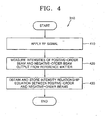
- operation 310 an intensity relationship equation between a positive-order beam and a negative-order beam is set. Operation 310 will be described in greater detail with reference to FIG. 4.
- the RF signal generator 113 applies an RF signal for generating a particular wavelength to the tunable filter 114.
- an RF signal having a frequency of 54-119 MHz is applied so that the tunable filter 114 can output light having a wavelength range of 1200-2400 nm, which includes a wavelength ranging from 1500 to 1700 nm and a wavelength of 2100 nm.
- a second reference matter (not shown) is substituted for the subject 120 so that the positive-order beam 115 and the negative-order beam 117 generated by the tunable filter 114 according to the RF signal are both radiated onto the reference matter 121 in the container, and an intensity of a positive-order beam output from the reference matter and an intensity of a negative-order beam output from the reference matter may be measured.
- the RF signal generator 113 applies an RF signal having a predetermined frequency to the tunable filter 114 to generate light having a second wavelength band from light having a first wavelength band emitted from the light source 111.
- the positive-order beam 115 and the negative-order beam 117 are generated by the tunable filter 114 according to the RF signal and radiated onto the subject 120 and the reference matter 121, respectively, through the first and second beam guiding units 118 and 119, so that a positive-order beam and a negative-order beam respectively output from the subject 120 and the reference matter 121 are acquired. Intensities of the positive-order beam output from the subject 120 and the negative-order beam output from the reference matter 121 are then measured.
- absorbance is calculated using the positive-order beam output from the subject 120 obtained in operation 330 and the positive-order beam output from the reference matter 121 obtained in operation 340, i.e., the positive-order beam input to the subject 120.
- a concentration of the component is measured using the absorbance. More specifically, the intensity of the positive-order beam output from the subject 120 is set as a signal light intensity, the intensity of the positive-order beam input to the subject 120 is set as a reference light intensity, and a negative log ratio between the signal light intensity and the reference light intensity is calculated to determine the absorbance.
- the intensity of a positive-order beam output from the subject 120 is directly detected by the first light detector 122.
- the intensity of a positive-order beam input to the subject 120 is calculated by applying a negative-order beam output from the reference matter 121 and detected by the second light detector 123 to the previously provided intensity relationship equation between a positive-order beam and a negative-order beam. Accordingly, the intensity of an input beam of the subject 120 and the intensity of an output beam of the subject 120 can be simultaneously measured without a measurement time difference.
- the actual concentration of a component can be accurately calculated using absorbance calculated from the intensities of the input and output beams and an algorithm for predicting a concentration of the component.
- the algorithm can be obtained using a multivariate regression method, such as a partial least squares regression (PLSR) method.
- PLSR partial least squares regression
- the subject need not be a human or animal body.
- the subject is tissue already removed form the body.
- the subject can be any component in any subject, and in particular can be a component in a subject not part of the human or animal body.
- the present invention can be realized as a code which is recorded on a computer readable recording medium and can be read by a computer.
- the computer readable recording medium may be any type of medium on which data that can be read by a computer system can be recorded, for example, a ROM, a RAM, a CD-ROM, a magnetic tape, a floppy disc, or an optical data storage device.
- the present invention can also be realized as code transported on carrier waves (for example, transmitted through Internet).
- computer readable recording media may be distributed among computer systems connected through a network so that the present invention may be realized as a code that is stored in the recording media and can be read and executed in computers. Functional programs, codes, and code segments for implementing the present invention can be easily inferred by programmers in the art of the present invention.
- a difference between a measurement time of a reference light intensity and a signal light intensity is removed.
- the reference light intensity is obtained without encountering a subject to be measured, i.e., an intensity of an input beam of the subject, and a measurement time of a signal light intensity is obtained when the subject is encountered, i.e., an intensity of an output beam of the subject.
- a measurement time difference is removed, an accurate concentration of a component of a subject, such as bodily fluid, can be invasively or non-invasively measured without being influenced by various changes occurring during a conventional measurement time difference.
- a tunable filter composed of an acoustic-optic device is used without using any moving mechanical elements, influence of an external environment, such as a vibration or a shock, is reduced, and fast wavelength scanning is possible.
- a spectrum bandwidth of a light source can be freely controlled by adjusting the frequency of an RF signal applied to the tunable filter. Therefore, the concentration of a component having a narrow absorption band can be easily measured.
Claims (6)
- Procédé de mesure d'une concentration d'un composant dans un objet, comprenant les étapes consistant à :■ projeter un faisceau lumineux, ayant une première bande de longueur d'onde absorbée par le composant, sur un filtre à accord variable fonctionnellement connecté à un générateur de signal RF ;■ appliquer un signal RF ayant une fréquence prédéterminée au dit filtre à accord variable afin de générer à partir dudit faisceau lumineux un faisceau d'ordre positif et un faisceau d'ordre négatif, ledit faisceau d'ordre positif et ledit faisceau d'ordre négatif ayant une seconde bande de longueur d'onde qui est absorbée par le composant devant être détecté ;■ projeter ledit faisceau d'ordre positif sur l'objet et détecter un faisceau de sortie réfléchi par ou transmis à travers ledit objet ; et■ projeter ledit faisceau d'ordre négatif sur une substance de référence et détecter un faisceau de sortie réfléchi par ou transmis à travers ladite substance de référence ;ledit procédé étant caractérisé en ce qu'il comprend en outre les étapes consistant à :■ établir une équation de relation d'intensité entre un faisceau d'ordre positif et un faisceau d'ordre négatif par rapport à une substance de référence à une longueur d'onde donnée ;■ calculer une intensité du faisceau d'ordre positif projeté sur l'objet en appliquant ledit faisceau de sortie d'ordre négatif détecté à ladite équation de relation d'intensité ;■ calculer une absorbance en utilisant l'intensité détectée du faisceau d'ordre positif sorti de l'objet et l'intensité calculée du faisceau d'ordre positif entré dans l'objet ; et■ calculer une concentration du composant en utilisant l'absorbance calculée.
- Procédé selon la revendication 1, dans lequel l'établissement de l'équation de relation d'intensité comprend les étapes consistant à :■ générer les faisceaux d'ordre positif et d'ordre négatif ayant la seconde bande de longueur d'onde à partir de la lumière qui a la première bande de longueur d'onde et est délivrée par une source de lumière, en fonction d'un signal à radiofréquence (RF) ayant une fréquence prédéterminée ;■ projeter les faisceaux d'ordre positif et d'ordre négatif sur la substance de référence et détecter les intensités des faisceaux d'ordre positif et d'ordre négatif respectifs sortis de la substance de référence ; et■ établir l'équation de relation d'intensité sur la base des intensités détectées des faisceaux d'ordre positif et d'ordre négatif (115, 117).
- Support d'enregistrement lisible par ordinateur sur lequel est enregistré un programme permettant d'exécuter la méthode selon la revendication 1 ou la revendication 2.
- Dispositif pour mesurer une concentration d'un composant dans un objet, comprenant :■ une source de lumière (111) qui est agencée de façon à générer une lumière ayant une première bande de longueur d'onde à destination du composant ;■ un générateur de signal à radiofréquence (RF) (113) qui est agencé de façon à générer un signal à radiofréquence (RF) ayant une fréquence prédéterminée de telle manière qu'une lumière ayant une seconde bande de longueur d'onde peut être générée à partir de la lumière ayant la première bande de longueur d'onde ;■ un filtre à accord variable (114) agencé de façon à recevoir la lumière ayant la première bande de longueur d'onde et à générer un faisceau d'ordre positif (115) et un faisceau d'ordre négatif (117), qui ont la seconde bande de longueur d'onde, en fonction du signal RF produit par le générateur de signal RF (113) ;■ un premier détecteur de lumière (122) conçu pour détecter un premier faisceau de sortie réfléchi par ou transmis à travers l'objet (120) sur lequel le faisceau d'ordre positif généré par le filtre à accord variable a été projeté ;■ un second détecteur de lumière (123) conçu pour détecter un second faisceau de sortie réfléchi par ou transmis à travers une substance de référence (121) sur laquelle le faisceau d'ordre négatif généré par le filtre à accord variable a été projeté ; et un processeur de signal (126) ;caractérisé en ce que le processeur de signal (126) reçoit une équation de relation d'intensité entre le faisceau d'ordre positif et le faisceau d'ordre négatif par rapport à une substance de référence à une longueur d'onde donnée, et est agencé de façon à calculer une intensité du faisceau d'ordre positif entré dans l'objet en appliquant une intensité du second faisceau de sortie à partir de la substance de référence à l'équation de relation d'intensité, afin de calculer une absorbance en utilisant l'intensité détectée du premier faisceau de sortie à partir de l'objet et l'intensité calculée du faisceau d'ordre positif entré dans l'objet, puis de calculer une concentration du composant en utilisant l'intensité calculée.
- Dispositif selon la revendication 4, comprenant en outre des première et seconde unités de guidage de faisceau (118, 119) adaptées pour guider le faisceau d'ordre positif (115) généré par le filtre à accord variable (114), devant être transmis en parallèle à l'objet (120), et le faisceau d'ordre négatif (117) généré par le filtre à accord variable (114), devant être transmis en parallèle à la substance de référence (121).
- Dispositif selon la revendication 5, comprenant en outre une unité d'adaptation d'indice de réfraction, qui est disposée entre la première unité de guidage de faisceau (118) et l' objet (120) afin d'adapter un indice de réfraction interne de l'objet à un indice de réfraction externe de l'objet.
Applications Claiming Priority (2)
| Application Number | Priority Date | Filing Date | Title |
|---|---|---|---|
| KR2003016406 | 2003-03-17 | ||
| KR10-2003-0016406A KR100464324B1 (ko) | 2003-03-17 | 2003-03-17 | 목적물의 성분농도 측정방법 및 장치 |
Publications (2)
| Publication Number | Publication Date |
|---|---|
| EP1460413A1 EP1460413A1 (fr) | 2004-09-22 |
| EP1460413B1 true EP1460413B1 (fr) | 2006-08-09 |
Family
ID=36934180
Family Applications (1)
| Application Number | Title | Priority Date | Filing Date |
|---|---|---|---|
| EP20040251518 Expired - Lifetime EP1460413B1 (fr) | 2003-03-17 | 2004-03-17 | Procédé et dispositif de mesure in vitro ou in vivo de la concentration d'un composant |
Country Status (6)
| Country | Link |
|---|---|
| US (1) | US7107087B2 (fr) |
| EP (1) | EP1460413B1 (fr) |
| JP (1) | JP4361822B2 (fr) |
| KR (1) | KR100464324B1 (fr) |
| CN (1) | CN1314368C (fr) |
| DE (1) | DE602004001794T2 (fr) |
Cited By (1)
| Publication number | Priority date | Publication date | Assignee | Title |
|---|---|---|---|---|
| WO2019138396A1 (fr) * | 2018-01-15 | 2019-07-18 | Vital Biosciences Inc. | Analyse d'échantillon fondée sur l'émittance d'ondes électromagnétiques |
Families Citing this family (19)
| Publication number | Priority date | Publication date | Assignee | Title |
|---|---|---|---|---|
| BRPI0816925B8 (pt) | 2007-09-13 | 2021-06-22 | Univ Missouri | funil de luz de iluminação, funil de captação de luz e aparelho |
| BRPI0818177B1 (pt) * | 2007-10-04 | 2022-09-27 | The Curators Of The University Of Missouri | Aparelho |
| US7961305B2 (en) * | 2007-10-23 | 2011-06-14 | The Curators Of The University Of Missouri | Optical device components |
| WO2009120600A2 (fr) * | 2008-03-25 | 2009-10-01 | The Curators Of The University Of Missouri | Procédé et système pour une détection non invasive de la glycémie utilisant des données spectrales d’un ou plusieurs constituants autres que le glucose |
| DE102008017119A1 (de) * | 2008-04-02 | 2009-10-08 | Polytec Gmbh | Vibrometer und Verfahren zur optischen Vermessung eines Objekts |
| WO2009142853A1 (fr) | 2008-05-22 | 2009-11-26 | The Curators Of The University Of Missouri | Procédé et système de détection optique non invasif du glucose sanguin utilisant l’analyse de données spectrales |
| CN102438511B (zh) | 2009-04-01 | 2014-11-26 | 密苏里大学董事会 | 用于无创血糖检测的光谱分析设备和相关使用方法 |
| WO2013141414A1 (fr) * | 2012-03-19 | 2013-09-26 | Lg Electronics Inc. | Procédé de compensation de signal de sortie de biocapteur optique et biocapteur optique utilisant celui-ci |
| DE102012018357A1 (de) | 2012-09-17 | 2014-03-20 | Liebherr-Hausgeräte Ochsenhausen GmbH | Kühl- und/oder Gefriergerät |
| US10168305B2 (en) | 2013-10-17 | 2019-01-01 | Battelle Memorial Institute | Container screening system and method |
| US10724968B2 (en) | 2014-03-21 | 2020-07-28 | Battelle Memorial Institute | System and method for solution constituent and concentration identification |
| US10234404B2 (en) | 2014-03-21 | 2019-03-19 | Battelle Memorial Institute | Liquid scanning system and method for IV drug verification and identification |
| SG11201701015QA (en) * | 2014-08-29 | 2017-03-30 | Univ Tohoku | Optical concentration measuring method |
| CN104257390B (zh) * | 2014-09-04 | 2016-04-20 | 深圳市前海安测信息技术有限公司 | 无创血糖测定方法及系统 |
| CN104490403B (zh) * | 2014-12-06 | 2016-08-17 | 深圳市贝沃德克生物技术研究院有限公司 | 基于光谱技术的无创血糖测量系统及其测量方法 |
| CN105424644B (zh) * | 2016-01-18 | 2019-04-23 | 中国工程物理研究院流体物理研究所 | 一种用于安全检查的近红外激光照明成像系统及方法 |
| EP3685144A4 (fr) * | 2017-09-21 | 2021-07-07 | Vital Biosciences Inc. | Imagerie d'un tissu biologique ou d'autres sujets |
| US10746716B1 (en) | 2019-05-31 | 2020-08-18 | Battelle Memorial Institute | System and method for solution constituent and concentration identification |
| KR102656429B1 (ko) * | 2022-02-08 | 2024-04-12 | 한국자동차연구원 | 단일 파장 레이저와 파장 필터를 이용한 형상 및 분광 정보 동시 측정 시스템 및 방법 |
Family Cites Families (11)
| Publication number | Priority date | Publication date | Assignee | Title |
|---|---|---|---|---|
| US4663961A (en) * | 1985-09-17 | 1987-05-12 | Westinghouse Electric Corp. | System for remote chemical analysis |
| US4771829A (en) * | 1987-12-30 | 1988-09-20 | Sparlin Derry D | Well liner with selective isolation screen |
| US5086229A (en) | 1989-01-19 | 1992-02-04 | Futrex, Inc. | Non-invasive measurement of blood glucose |
| US5222495A (en) | 1990-02-02 | 1993-06-29 | Angiomedics Ii, Inc. | Non-invasive blood analysis by near infrared absorption measurements using two closely spaced wavelengths |
| US5039855A (en) * | 1990-03-05 | 1991-08-13 | Bran+Luebbe Analyzing Technologies, Inc. | Dual beam acousto-optic tunable spectrometer |
| AU2245092A (en) | 1991-12-31 | 1993-07-28 | Vivascan Corporation | Blood constituent determination based on differential spectral analysis |
| US5477321A (en) | 1994-08-31 | 1995-12-19 | Bayer Corporation | Dual beam tunable spectrometer |
| US5655530A (en) * | 1995-08-09 | 1997-08-12 | Rio Grande Medical Technologies, Inc. | Method for non-invasive blood analyte measurement with improved optical interface |
| US6152876A (en) | 1997-04-18 | 2000-11-28 | Rio Grande Medical Technologies, Inc. | Method for non-invasive blood analyte measurement with improved optical interface |
| CN1095355C (zh) * | 1996-01-22 | 2002-12-04 | 北京大学 | 中红外光纤测定人体血糖的方法 |
| EP2400288A1 (fr) * | 2002-02-11 | 2011-12-28 | Bayer Corporation | Dispositif non-invasif de détermination d'analytes dans des fluides physiologiques |
-
2003
- 2003-03-17 KR KR10-2003-0016406A patent/KR100464324B1/ko active IP Right Grant
-
2004
- 2004-03-16 JP JP2004074680A patent/JP4361822B2/ja not_active Expired - Lifetime
- 2004-03-17 EP EP20040251518 patent/EP1460413B1/fr not_active Expired - Lifetime
- 2004-03-17 DE DE200460001794 patent/DE602004001794T2/de not_active Expired - Lifetime
- 2004-03-17 US US10/801,612 patent/US7107087B2/en active Active
- 2004-03-17 CN CNB2004100631185A patent/CN1314368C/zh not_active Expired - Lifetime
Cited By (2)
| Publication number | Priority date | Publication date | Assignee | Title |
|---|---|---|---|---|
| WO2019138396A1 (fr) * | 2018-01-15 | 2019-07-18 | Vital Biosciences Inc. | Analyse d'échantillon fondée sur l'émittance d'ondes électromagnétiques |
| US10761019B2 (en) | 2018-01-15 | 2020-09-01 | Vital Biosciences Inc. | Electromagnetic wave emittance-based specimen analysis |
Also Published As
| Publication number | Publication date |
|---|---|
| US7107087B2 (en) | 2006-09-12 |
| CN1314368C (zh) | 2007-05-09 |
| KR20040081852A (ko) | 2004-09-23 |
| US20040186361A1 (en) | 2004-09-23 |
| DE602004001794D1 (de) | 2006-09-21 |
| DE602004001794T2 (de) | 2007-08-16 |
| JP4361822B2 (ja) | 2009-11-11 |
| JP2004279427A (ja) | 2004-10-07 |
| CN1550213A (zh) | 2004-12-01 |
| KR100464324B1 (ko) | 2005-01-03 |
| EP1460413A1 (fr) | 2004-09-22 |
Similar Documents
| Publication | Publication Date | Title |
|---|---|---|
| EP1460413B1 (fr) | Procédé et dispositif de mesure in vitro ou in vivo de la concentration d'un composant | |
| US5460177A (en) | Method for non-invasive measurement of concentration of analytes in blood using continuous spectrum radiation | |
| US8078250B2 (en) | Method for spectrophotometric blood oxygenation monitoring | |
| US5360004A (en) | Non-invasive determination of analyte concentration using non-continuous radiation | |
| Yamakoshi et al. | Pulse glucometry: a new approach for noninvasive blood glucose measurement using instantaneous differential near-infrared spectrophotometry | |
| CA2259254C (fr) | Capteur implantable et systeme de mesure et de controle in vivo de taux de constituants de fluides | |
| US6741876B1 (en) | Method for determination of analytes using NIR, adjacent visible spectrum and discrete NIR wavelenths | |
| US6456862B2 (en) | Method for non-invasive spectrophotometric blood oxygenation monitoring | |
| US5348003A (en) | Method and apparatus for chemical analysis | |
| US8406839B2 (en) | Method and apparatus for determining blood analytes | |
| WO1991015991A1 (fr) | Procede et appareil de controle non invasif d'analytes du sang par photoplethysmographie pulsatile | |
| JPS60236631A (ja) | グルコースの測光検出装置 | |
| WO2001016577A1 (fr) | Procede de determination d'analytes au moyen d'un spectre en proche infrarouge, d'un spectre visible adjacent et de longueurs d'ondes distinctes de spectre en proche infrarouge | |
| CN115399759A (zh) | 无创性血液分析 | |
| EP0623307A1 (fr) | Détermination non-invasive de la concentration de constituants par radiation non-continue | |
| US20050154268A1 (en) | Body component concentration measuring apparatus and method | |
| US8523785B2 (en) | Method and apparatus for measuring analytes | |
| US20230148312A1 (en) | Device for non-invasive blood glucose concentration measurement | |
| EP0623308A1 (fr) | Mesure non-invasive de la concentration de constituants du sang | |
| JP3694291B2 (ja) | 血糖値の無侵襲測定装置 | |
| WO2019208561A1 (fr) | Procédé de mesure de la concentration sanguine de composant sanguin, dispositif et programme de mesure de la concentration sanguine | |
| WO1996013201A1 (fr) | Procede non invasif de mesure de la concentration d'un analyte dans le sang | |
| WO1996013204A1 (fr) | Procede de determination de la concentration d'un analyte au moyen d'un rayonnement non continu |
Legal Events
| Date | Code | Title | Description |
|---|---|---|---|
| PUAI | Public reference made under article 153(3) epc to a published international application that has entered the european phase |
Free format text: ORIGINAL CODE: 0009012 |
|
| 17P | Request for examination filed |
Effective date: 20040331 |
|
| AK | Designated contracting states |
Kind code of ref document: A1 Designated state(s): AT BE BG CH CY CZ DE DK EE ES FI FR GB GR HU IE IT LI LU MC NL PL PT RO SE SI SK TR |
|
| AX | Request for extension of the european patent |
Extension state: AL HR LT LV MK |
|
| RIN1 | Information on inventor provided before grant (corrected) |
Inventor name: YOON, GIL-WON Inventor name: HWANG, IN-DUK Inventor name: HAN, SANG-JOON Inventor name: JEON, KYE-JIN |
|
| 17Q | First examination report despatched |
Effective date: 20050317 |
|
| AKX | Designation fees paid |
Designated state(s): DE FR GB |
|
| GRAP | Despatch of communication of intention to grant a patent |
Free format text: ORIGINAL CODE: EPIDOSNIGR1 |
|
| GRAS | Grant fee paid |
Free format text: ORIGINAL CODE: EPIDOSNIGR3 |
|
| GRAA | (expected) grant |
Free format text: ORIGINAL CODE: 0009210 |
|
| AK | Designated contracting states |
Kind code of ref document: B1 Designated state(s): DE FR GB |
|
| REG | Reference to a national code |
Ref country code: GB Ref legal event code: FG4D |
|
| REF | Corresponds to: |
Ref document number: 602004001794 Country of ref document: DE Date of ref document: 20060921 Kind code of ref document: P |
|
| ET | Fr: translation filed | ||
| PLBE | No opposition filed within time limit |
Free format text: ORIGINAL CODE: 0009261 |
|
| STAA | Information on the status of an ep patent application or granted ep patent |
Free format text: STATUS: NO OPPOSITION FILED WITHIN TIME LIMIT |
|
| 26N | No opposition filed |
Effective date: 20070510 |
|
| REG | Reference to a national code |
Ref country code: FR Ref legal event code: PLFP Year of fee payment: 13 |
|
| REG | Reference to a national code |
Ref country code: FR Ref legal event code: PLFP Year of fee payment: 14 |
|
| REG | Reference to a national code |
Ref country code: FR Ref legal event code: PLFP Year of fee payment: 15 |
|
| PGFP | Annual fee paid to national office [announced via postgrant information from national office to epo] |
Ref country code: FR Payment date: 20230221 Year of fee payment: 20 |
|
| PGFP | Annual fee paid to national office [announced via postgrant information from national office to epo] |
Ref country code: GB Payment date: 20230216 Year of fee payment: 20 Ref country code: DE Payment date: 20230222 Year of fee payment: 20 |
|
| P01 | Opt-out of the competence of the unified patent court (upc) registered |
Effective date: 20230520 |
|
| REG | Reference to a national code |
Ref country code: DE Ref legal event code: R071 Ref document number: 602004001794 Country of ref document: DE |
|
| REG | Reference to a national code |
Ref country code: GB Ref legal event code: PE20 Expiry date: 20240316 |
|
| PG25 | Lapsed in a contracting state [announced via postgrant information from national office to epo] |
Ref country code: GB Free format text: LAPSE BECAUSE OF EXPIRATION OF PROTECTION Effective date: 20240316 |