EP1460269A2 - Grundträger für einen Kompressor mit Antriebsmotor - Google Patents
Grundträger für einen Kompressor mit Antriebsmotor Download PDFInfo
- Publication number
- EP1460269A2 EP1460269A2 EP04006524A EP04006524A EP1460269A2 EP 1460269 A2 EP1460269 A2 EP 1460269A2 EP 04006524 A EP04006524 A EP 04006524A EP 04006524 A EP04006524 A EP 04006524A EP 1460269 A2 EP1460269 A2 EP 1460269A2
- Authority
- EP
- European Patent Office
- Prior art keywords
- frame
- air compressor
- disposed
- support plate
- compressor assembly
- Prior art date
- Legal status (The legal status is an assumption and is not a legal conclusion. Google has not performed a legal analysis and makes no representation as to the accuracy of the status listed.)
- Granted
Links
- 239000012530 fluid Substances 0.000 claims abstract description 36
- 230000005484 gravity Effects 0.000 claims abstract description 10
- 238000000034 method Methods 0.000 claims description 7
- 230000013011 mating Effects 0.000 claims 2
- 230000000087 stabilizing effect Effects 0.000 claims 1
- 230000000712 assembly Effects 0.000 description 3
- 238000000429 assembly Methods 0.000 description 3
- 238000001816 cooling Methods 0.000 description 2
- 238000005461 lubrication Methods 0.000 description 2
- 238000002485 combustion reaction Methods 0.000 description 1
- 238000010276 construction Methods 0.000 description 1
- 230000009977 dual effect Effects 0.000 description 1
- 239000000446 fuel Substances 0.000 description 1
- 210000003141 lower extremity Anatomy 0.000 description 1
- 239000000463 material Substances 0.000 description 1
- 238000004806 packaging method and process Methods 0.000 description 1
- 230000000149 penetrating effect Effects 0.000 description 1
- 210000001364 upper extremity Anatomy 0.000 description 1
Images




Classifications
-
- F—MECHANICAL ENGINEERING; LIGHTING; HEATING; WEAPONS; BLASTING
- F04—POSITIVE - DISPLACEMENT MACHINES FOR LIQUIDS; PUMPS FOR LIQUIDS OR ELASTIC FLUIDS
- F04B—POSITIVE-DISPLACEMENT MACHINES FOR LIQUIDS; PUMPS
- F04B35/00—Piston pumps specially adapted for elastic fluids and characterised by the driving means to their working members, or by combination with, or adaptation to, specific driving engines or motors, not otherwise provided for
- F04B35/06—Mobile combinations
Definitions
- the present invention relates in general to air compressors and more specifically to a support structure for a portable air compressor.
- Air compressors normally provide a source of pressurized air which is temporarily stored in a pressure tank.
- a motivating means typically an electric motor or a combustion engine, is connected to a compressor unit.
- the compressor unit typically includes a piston assembly, or compressor pump, which compresses air from the atmosphere and forces it into the fluid pressure tank for temporary storage.
- structural frames are provided. The frames normally provide at least one wheel for mobility of the air compressor assembly.
- the first drawback is that the component parts of the air compressor assembly, typically items that include the muffler from a gasoline engine and the air filter for the engine, and the cooling head for the compressor, are often arranged outside of the structural envelope of the frame supporting the air compressor assembly.
- Other smaller items such as the bleed and drain valve for the fluid pressure tank, the individual gages used to determine the pressure of the system, and drain ports from the various operating components are also frequently exposed (i.e., extending outside of an envelope of the frame). Exposed components are susceptible to damage.
- a portable air compressor assembly in one preferred embodiment, includes a frame having a pair of parallel side sections.
- a support plate is horizontally connected between the side sections in a compressor normal operating position.
- a plurality of operating components connect to the support plate.
- a fluid pressure tank is supported perpendicular to the side sections and forward of the operating components.
- the frame side sections envelope an outer perimeter of the operating components and angularly extend to a frame rotation stop point rearward of the operating components. When tipped rearward to the frame rotation stop point, the compressor assembly returns by gravity to the compressor normal operating position.
- a support structure for a portable air compressor in another preferred embodiment, includes a frame having a pair of approximately parallel side sections and a support plate horizontally disposed between the side sections. A plurality of components are connected to the support plate including an engine, a compressor and a fluid pressure tank. An axle is slidably disposed through a lower tubular portion of both side sections, the axle having distal ends operably forming opposed outer planar envelopes of the portable air compressor. An instrument support panel is connectably disposed on the frame and positioned adjacent to a select one of the outer planar envelopes.
- a plurality of instruments including an engine on/off switch, at least one pressure gage, at least one quick-disconnect fitting and at least one unloader valve are each mounted on the instrument support panel such that each of the instruments and the instrument support plate are completely disposed within one of the selected outer planar envelopes.
- Wheels rotatably supported on the axle, and structural feet are used to support the assembly and are each removable for shipping.
- a center-of- gravity for the assembly is positioned forward of the wheels such that when the assembly tips rearward, the center-of-gravity remains forward of a vertical axis taken through the axle, biasing the assembly to return to a normal operating position by gravity.
- the side sections provide dual lift handles for the assembly.
- a centrally positioned handle is retractable or removable for shipping.
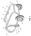
- FIG. 1 shows an air compressor assembly 10 according to a preferred embodiment of the present invention.
- the air compressor assembly 10 includes a frame 12, a component group 14, and a fluid pressure tank 16.
- a first wheel 18 and a second wheel 20 are rotatably supported from the frame 12 at an aft end of the air compressor assembly 10.
- the frame 12 includes a first side 22 and a second side 24.
- the first side 22 and the second side 24 are generally tubular shaped frame members generally formed in a parallelogram configuration having rounded corners.
- a support plate 26 is provided at a lower portion of the frame 12 and is mechanically joined to the first side 22 and the second side 24, respectively.
- a pair of support feet 28 (only one is visible in this view) are mechanically joined to a forward end of the frame 12 at an under surface of the support plate 26 as described in better detail in reference to Figure 9.
- Each of the support feet 28 includes an elastomeric pad 30.
- the purpose of the elastomeric pad 30 is to reduce the sliding motion of the air compressor assembly 10 when the engine is operating and to prevent the unit from sliding when placed on a relatively smooth surface.
- a control panel 32 is provided on either the first side 22 or the second side 24. In the embodiment shown, the control panel 32 is supported by an upper horizontal and a lower horizontal member of the first side 22. The control panel 32 is further described in reference to Figure 3.
- a rear support member 34 is provided to structurally join the first side 22 to the second side 24. The rear support member 34 also serves as a portion of a frame rotation stop point where the frame 12 contacts the ground surface as described in better detail in reference to Figure 5. In a preferred embodiment, the rear support member 34 and the support plate 26 are each welded to the first side 22 and the second side 24.
- the frame 12 is configured such that the component group 14 is totally enclosed within an envelope of the frame 12.
- An assembly longitudinal axis A is shown bisecting the frame 12.
- the fluid pressure tank 16 includes a tank longitudinal axis B positioned approximately perpendicular to the assembly longitudinal axis A.
- control panel 32 is supported at both an upper and lower extremity to the frame 12.
- the control panel 32 is mechanically fastened (e.g., welded) at joints 33 to the frame 12.
- the control panel 32 is shown in Figure 3 in a generally vertical orientation, however, the control panel 32 can also be supported along a major side using a mechanically fastened joint similar to joint 33 to either an upper horizontal or a lower horizontal portion of the frame 12.
- a plurality of components are mounted on the control panel 32.
- the control panel includes at least one pressure gage 36, an air regulator adjustment knob 37, an unloader valve 38, an engine on/off switch 39, and a pair of quick disconnect fittings 40.
- the arrangement of components on the control panel 32 is exemplary of a plurality of configurations of the pressure gages 36, the unloader valve 38, the on/off switch 39, and the quick disconnect fittings 40 that are possible.
- a rear tubular member 41 joins an upper horizontal to a lower horizontal tube of the frame 12 for both the first side 22 (not shown) and the second side 24.
- Each rear tubular member 41 forms a frame clearance angle ⁇ from a ground surface C as shown.
- the frame clearance angle ⁇ permits the air compressor assembly 10 to be rotated about an axis of rotation D formed at the center of each of the first wheel 18 (not shown) and the second wheel 20.
- An axle vertical axis E extends from the axis of rotation D.
- a center-of-gravity 42 is disposed forward of the axle vertical axis E.
- the position shown for the air compressor assembly 10 in Figure 4 is the normal operating position having each of the first wheel 18 and the second wheel 20 and each of the support feet 28 contacting the ground surface C. It will be apparent to a person of skill that the ground surface C can vary in geometry from that shown such that the normal operating position can vary providing that each of the wheels and the support feet contact the ground surface C. Also as shown in Figure 4, the second wheel 20 (as well as the first wheel 18, not shown) are positioned at a rear-most portion of the lower horizontal tube of the frame 12. The fluid pressure tank 16 is generally positioned over the support feet 28 as shown. The configuration of the frame 12 therefore provides the wheels (18, 20) and the support feet 28 adjacent to the heaviest components to adequately support the components of the air compressor assembly 10. References herein to forward and rear (and rearward) directions are in relation to the forward direction arrow F.
- the air compressor assembly 10 is rotated about the axis of rotation D in the lift rotation direction H, until the rear tubular member 41 and/or the rear support member 34 contact the ground surface C.
- a frame rotation stop point 44 is shown at the point of contact between the frame 12 and the ground surface C.
- the center-of-gravity 42 remains forward of the axle vertical axis E.
- the frame 12 in this position is rotated to an assembly rotation angle ⁇ from the ground surface C.
- gravity will bias the air compressor assembly 10 to rotate in the return rotation direction J about the axis of rotation D to return to the normal operating position shown in Figure 4.
- the maximum assembly rotation angle ⁇ will depend on several variables including (with reference to Figure 4), the distance X between the axle vertical axis E and a rearward facing end of the frame 12, a radius of the wheels Y, and the height Z from the ground surface C to the frame rotation stop point 44.
- a total height T and a total length V for the air compressor assembly 10 are shown.
- the total height T is approximately 51 cm (20")
- the total length V is approximately 119 cm (47"). It will be the obvious that the dimensions of the present invention can be varied without departing from the spirit and scope of the present invention.
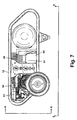
- the engine 50 includes a drive pulley 54 coupled by a V-belt (not shown) to a rotating pulley 56 of the compressor pump 52.
- the arrangement of the engine 50, the compressor pump 52, and the fluid pressure tank 16 is selected to generally evenly distribute the weight of these components about the assembly longitudinal axis A.
- the first side 22 provides a pull/lift location 58 and the second side 24 provides a pull/lift location 60 to manually lift and move the air compressor assembly 10 from a forward end of the compressor assembly 10.
- the air compressor assembly 10 can be lifted from either of the pull/lift locations 58 or 60, respectively, however, to push the air compressor assembly 10 in a direction opposite to the forward direction F, it is preferable to hold both the pull/lift locations 58 and 60 simultaneously.
- the fluid pressure tank 16 is partially supported from the frame 12 by a pair of brackets 61 which are mechanically connected to each of a pair of tabs 62 welded to the fluid pressure tank 16.
- the axle 46 has distal ends which form each of an outer planar envelope K and an outer planar envelope L shown.
- the end caps 48 are included within the outer planar envelopes K and L, respectively.
- the frame 12 and all of the components including those mounted to the control panel 32 and bounded by the control panel outer envelope M are within the region bounded by the outer planar envelopes K and L, respectively.
- rear facing components of the engine 50 including a muffler 63, are positioned within the envelope of the frame 12.
- a compressor body 64 and a cooling head 66 of the compressor 52 also fit within the envelope of the frame 12. This arrangement reduces the potential for damage occurring to these components by extending beyond the protected boundary of the frame 12.
- the axle 46 is rotatably positioned through apertures (not shown) formed in the lower horizontal members of the first side 22 and the second side 24 of the frame 12 approximate an aft end of the compressor assembly 10.
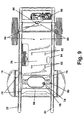
- the geometry and structure of the support feet 28 are also shown.
- the structure of the support feet 28 is mechanically fastened to the support plate 26 as best described in reference to Figure 9.
- the support feet 28 form a portion of a support structure 68 which includes arches 70 to separate each of the support feet 28.
- the arches 70 allow the air compressor assembly 10 to remain stationery and each of the support feet 28 in contact with the ground surface C when the ground surface C varies from the horizontal plane shown.
- an undersurface of the air compressor assembly 10 provides the support locations for the support plate 26 to each of the first side 22 and the second side 24, respectively.
- a plurality of weld joints 72 join portions of the support plate 26 to each of the first side 22 and the second side 24.
- a drain valve 74 for the fluid pressure tank 16 is accessible via an aperture 76 formed in the support structure 68.
- a raised area 78 of the support structure 68 adjacent to the drain valve 74 provides additional protection for the portion of the drain valve 74 extending below the outer circumference of the fluid pressure tank 16.
- the support structure 68 is mechanically connected to the fluid pressure tank 16 via a plurality of fasteners 80 and tabs (not shown).
- the compressor 52 (shown in Figure 7), is mounted to the support plate 26 via a plurality of fasteners 82.
- a drain fitting (not shown) for the compressor 52 is aligned with a drain aperture 84 through the support plate 26 in order to drain the lubrication fluid contents of the compressor 52.
- the engine 50 similarly shown in Figure 7, is mounted to the support plate 26 via a plurality of fasteners 86.
- a drain fitting 88 for the engine 50 has a drain aperture 90 aligned therewith to permit the lubrication fluid of the engine 50 to be drained.
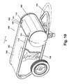
- the air compressor assembly 100 includes a frame 102, a component group 104, and a fluid pressure tank 106 similar to the air compressor assembly 10. Other components shown including the wheels and the control panel are similar to those shown for air compressor assembly 10 and are therefore not further discussed herein.
- the frame 102 includes a first side 108 and a second side 110, generally formed of tubular material. Each of the first side 108 and the second side 110 have distal ends 109 and 111, respectively positioned approximately in line with a longitudinal axis of the fluid pressure tank 106 as viewed from a plan view of the air compressor assembly 100.
- a pair of tabs 112 are joined by each of a pair of fasteners 114 to the first side 108 and the second side 110 on a first end and are welded to the fluid pressure tank 106 on a second end.
- the frame 102 is therefore connected at both an upper surface and a lower surface of the fluid pressure tank 106 and partially relies on the rigidity of the fluid pressure tank 106 to stiffen the frame 102.
- the frame 102 also includes a central lift section 116 which is aligned approximately with the assembly longitudinal axis (similar to the assembly longitudinal axis A of the air compressor assembly 10) at a forward end of the air compressor assembly 100.
- the central lift section 116 permits the air compressor assembly 100 to be pushed or pulled along the air compressor assembly 100 longitudinal axis.
- the central lift section 116 is extended in the forward direction F from a stowed position (shown) to an extended position (shown in phantom) and locked in the extended position. Additionally, the central lift section can be totally removed. Mechanical locking means to lock the central lift section 116 in either of the stowed or the extended positions such as spring loaded pins are known and are therefore not discussed further herein.
- a diameter of the central lift section 116 is made either smaller or larger than the diameter of both the first side 108 and the second side 110.
- a center-of-gravity for a compressor assembly is calculated.
- a pair of wheels having a common axis of rotation and a vertical axis disposed through the common axis of rotation is positioned aft of the center-of-gravity.
- a frame contact surface is extended rearward of the common rotation axis of the wheels.
- a lifting handle is disposed forward of the center-of-gravity.
- a rotation path for the compressor assembly is defined which varies between a normal operating position and a rotated position, the rotated position having the frame contact surface contacting a ground surface when the lifting handle is used to rotate the compressor assembly about the common axis of rotation.
- the frame contact surface is prepositioned to retain the center-of-gravity forward of the vertical axis, throughout the compressor assembly rotation path, to bias the compressor assembly to return by gravity from the rotated position to the normal operating position for any position of the compressor assembly along the rotation path.
- An air compressor assembly of the present invention offers several advantages.
- the rear frame geometry together with selected placement of the center-of-gravity of the unit reduces the likelihood that the air compressor assembly will tip over.
- a gravity bias returns the unit to the normal operating position.
- the frame of the air compressor assembly provides a totally enclosed volume to protect the equipment supported by the frame.
- the control panel of the present invention provides for all of the items mounted thereon to be contained within a planar envelope formed by the ends of the axle supporting the wheels. This reduces the potential to damage any of the components mounted on the control panel. Apertures are provided in the support plate to drain the fluids from the compressor and engine, as well as providing an access for operation of the drain and vent valve from the fluid pressure tank.
- the small space envelope of the assembly of the present invention permits the entire unit to be placed within standard compartments of commercially available trucks used in the construction industry.
- the wheels, the support feet, and the forward handle of the air compressor assembly are removable to facilitate a shipping configuration and packaging of the unit.
Landscapes
- Engineering & Computer Science (AREA)
- Mechanical Engineering (AREA)
- General Engineering & Computer Science (AREA)
- Compressors, Vaccum Pumps And Other Relevant Systems (AREA)
- Structures Of Non-Positive Displacement Pumps (AREA)
Applications Claiming Priority (2)
| Application Number | Priority Date | Filing Date | Title |
|---|---|---|---|
| US392567 | 2003-03-20 | ||
| US10/392,567 US7029240B2 (en) | 2002-10-10 | 2003-03-20 | Support structure for a portable air compressor |
Publications (3)
| Publication Number | Publication Date |
|---|---|
| EP1460269A2 true EP1460269A2 (de) | 2004-09-22 |
| EP1460269A3 EP1460269A3 (de) | 2006-07-26 |
| EP1460269B1 EP1460269B1 (de) | 2013-08-28 |
Family
ID=32824886
Family Applications (1)
| Application Number | Title | Priority Date | Filing Date |
|---|---|---|---|
| EP04006524.5A Expired - Lifetime EP1460269B1 (de) | 2003-03-20 | 2004-03-18 | Grundträger für einen Kompressor mit Antriebsmotor |
Country Status (5)
| Country | Link |
|---|---|
| US (2) | US7029240B2 (de) |
| EP (1) | EP1460269B1 (de) |
| CN (1) | CN100400872C (de) |
| DK (1) | DK1460269T3 (de) |
| ES (1) | ES2428890T3 (de) |
Cited By (1)
| Publication number | Priority date | Publication date | Assignee | Title |
|---|---|---|---|---|
| DE202006015542U1 (de) * | 2006-10-09 | 2007-11-22 | Syntecs Gmbh Reinigungssysteme | Hochdruckreiniger |
Families Citing this family (39)
| Publication number | Priority date | Publication date | Assignee | Title |
|---|---|---|---|---|
| US7163382B1 (en) * | 2003-04-09 | 2007-01-16 | Black & Decker Inc. | Suitcase style air compressor assembly |
| US7029240B2 (en) * | 2002-10-10 | 2006-04-18 | Black & Decker Inc. | Support structure for a portable air compressor |
| US20060104835A1 (en) * | 2003-04-09 | 2006-05-18 | Etter Mark A | Portable air compressor tool carrier |
| US7025573B1 (en) * | 2003-04-09 | 2006-04-11 | Black & Decker Inc. | Storage container for air compressor |
| US7909584B2 (en) * | 2004-01-30 | 2011-03-22 | Black & Decker Inc. | Air compressor |
| US7384245B2 (en) * | 2004-11-01 | 2008-06-10 | Alltrade Tools Llc | Compressor with rotating handle |
| US20060171820A1 (en) | 2005-01-31 | 2006-08-03 | Baron Michael P | Cooling arrangement for a portable air compressor |
| KR100646004B1 (ko) * | 2005-02-25 | 2006-11-23 | (주)오티 웰빙 | 개량형 에어콤프레샤 |
| US20060228228A1 (en) * | 2005-03-21 | 2006-10-12 | Wesolowski Gregory G | Engine mounting frame |
| DE102005018757B4 (de) * | 2005-04-24 | 2014-07-24 | SHG Spechtenhauser Hochwasser-und Gewässerschutz GmbH | Einmannpumpe mit Traggestell und Flachabsaugung vorzugsweise für Umweltschutz- und Katastropheneinsätze |
| EP1770279A3 (de) * | 2005-10-03 | 2011-10-26 | Black & Decker, Inc. | Druckluftverdichter |
| US20070134104A1 (en) * | 2005-12-12 | 2007-06-14 | Sullair Corporation | Modular portable compressor |
| USD542398S1 (en) | 2006-02-16 | 2007-05-08 | Desa Ip, Llc | Portable heater |
| USD542397S1 (en) | 2006-02-16 | 2007-05-08 | Desa Ip, Llc | Portable heater |
| USD545421S1 (en) | 2006-02-16 | 2007-06-26 | Desa Ip, Llc | Portable heater |
| USD536348S1 (en) | 2006-03-22 | 2007-02-06 | Campbell Hausfeld/Scott Fetzer Company | Compressor |
| USD536708S1 (en) | 2006-03-22 | 2007-02-13 | Campbell Hausfeld/Scott Fetzer Company | Compressor |
| US8584564B2 (en) * | 2006-04-21 | 2013-11-19 | Black & Decker Inc. | Table saw |
| CA117874S (en) * | 2006-04-26 | 2008-12-19 | Black & Decker Inc | Wheeled portable compressor |
| USD555173S1 (en) | 2006-05-26 | 2007-11-13 | Black & Decker Inc. | Compressor |
| US7600998B1 (en) | 2006-08-15 | 2009-10-13 | Eric Pitchford | Portable heater with roll cage |
| US20080044299A1 (en) * | 2006-08-18 | 2008-02-21 | Liquid Load Logistics, Llc | Apparatus, system and method for loading and offlloading a bulk fluid tanker |
| US20080219860A1 (en) * | 2007-03-08 | 2008-09-11 | Alltrade Tools Llc | Protection system for air compressor assembly |
| US20080240936A1 (en) * | 2007-04-02 | 2008-10-02 | Douglas Kent Ritterling | Portable air compressor |
| MX2011003672A (es) * | 2008-10-07 | 2011-05-02 | Techtronic Power Tools Tech | Compresor de aire portatil. |
| US8303261B1 (en) | 2009-01-30 | 2012-11-06 | Hawkins Bobby L | Wheeled, manually moveable air compressor |
| EP2320085A3 (de) * | 2009-11-05 | 2012-01-25 | Techtronic Power Tools Technology Limited | Tragbarer Luftkompressor |
| USD668607S1 (en) * | 2010-03-08 | 2012-10-09 | Briggs & Stratton Corporation | Frame for outdoor power equipment |
| USD662517S1 (en) | 2010-11-16 | 2012-06-26 | Hawkins Bobby L | Frame for a wheeled, manually moveable air compressor |
| CN102878055A (zh) * | 2012-09-28 | 2013-01-16 | 樊荣 | 一种便携式气泵 |
| US20150021878A1 (en) * | 2013-07-18 | 2015-01-22 | Variety Children's Hospital D/B/A Miami Children's Hospital | Portable cardiopulmonary support cart systems |
| USD788825S1 (en) * | 2015-05-04 | 2017-06-06 | American Fab, Inc. | Frame for air compressor |
| CN105201779A (zh) * | 2015-10-20 | 2015-12-30 | 无锡格莱德科技有限公司 | 一种防滑式空气压缩机 |
| CN105587657B (zh) * | 2016-03-03 | 2018-02-06 | 隆鑫通用动力股份有限公司 | 一种水泵安装架上的手把管 |
| USD806755S1 (en) * | 2016-10-31 | 2018-01-02 | Wood Industries Inc. | Compressor |
| USD806753S1 (en) * | 2016-10-31 | 2018-01-02 | Wood Industries Inc. | Compressor |
| CN109901236B (zh) * | 2019-03-05 | 2020-10-02 | 格尔木庆华矿业有限责任公司 | 一种用于铁矿的具有防护功能的探测仪器 |
| CN113217349B (zh) * | 2021-05-10 | 2024-11-05 | 浙江威普机电科技有限公司 | 一种空气压缩机 |
| CN118462539B (zh) * | 2024-06-05 | 2024-12-13 | 浙江永源机电制造有限公司 | 一种移动式空压机 |
Citations (1)
| Publication number | Priority date | Publication date | Assignee | Title |
|---|---|---|---|---|
| US20020131872A1 (en) | 2001-03-13 | 2002-09-19 | Fabio Lucchi | Portable compressor |
Family Cites Families (77)
| Publication number | Priority date | Publication date | Assignee | Title |
|---|---|---|---|---|
| US293585A (en) * | 1884-02-12 | Feank d | ||
| US278425A (en) * | 1883-05-29 | Machine and bolt works | ||
| US231226A (en) * | 1880-08-17 | Telephone-transmitter | ||
| US273011A (en) * | 1883-02-27 | barker | ||
| US445115A (en) * | 1891-01-20 | Beer-cooler | ||
| US450061A (en) * | 1891-04-07 | Leo ehelich | ||
| US423518A (en) * | 1890-03-18 | Steam-generator and furnace | ||
| US352293A (en) * | 1886-11-09 | Balanced piston | ||
| US144482A (en) * | 1873-11-11 | Improvement in wood-sawing machines | ||
| US352292A (en) * | 1886-11-09 | Breech loading fire arm | ||
| US140642A (en) * | 1873-07-08 | Improvement in medical compounds for cholera | ||
| US293584A (en) * | 1884-02-12 | Barb for fence-wire | ||
| US185000A (en) * | 1876-12-05 | Improvement in harvester-rakes | ||
| US293446A (en) * | 1884-02-12 | Thomas s | ||
| US243282A (en) * | 1881-06-21 | Manufacture of g lass-i nsu l ate d telegraph-wires | ||
| US249265A (en) * | 1881-11-08 | Ohaeles e | ||
| US170330A (en) * | 1875-11-23 | Improvement in vats for tanning leather | ||
| US197860A (en) * | 1877-12-04 | Improvement in sand-paper rollers for buffing shoe-soles | ||
| US223039A (en) * | 1879-12-30 | Improvement in beaters for cotton-openers | ||
| US273493A (en) * | 1883-03-06 | Valve-gear for electrical generator-engines | ||
| US449311A (en) * | 1891-03-31 | Cash register | ||
| US352294A (en) * | 1886-11-09 | Addie bond | ||
| US1756806A (en) * | 1927-10-28 | 1930-04-29 | Howard W Beach | Portable air-compressing unit |
| US2074293A (en) * | 1933-12-02 | 1937-03-16 | Wohlmeyer Josef | Traveling motor compressor |
| US2434675A (en) * | 1944-02-05 | 1948-01-20 | Ernest H Simpson | Governor for power driven air supply units |
| US2490305A (en) | 1946-07-16 | 1949-12-06 | Charles S Jones | Portable motor operated air compressor with storage tank |
| US2521313A (en) | 1946-08-21 | 1950-09-05 | Jerry C Stokes | Combined spraying and compressor unit |
| US2685404A (en) | 1950-06-20 | 1954-08-03 | Wohlmeyer Josef Albert | Mobile air compressor unit |
| DE903023C (de) * | 1950-06-20 | 1954-02-01 | Josef Wohlmeyer Dipl Ing | Ortsbewegliches Drucklufterzeugungsaggregat |
| US2804259A (en) * | 1954-05-10 | 1957-08-27 | Clarence J Ralston | Portable air compressor |
| US2812895A (en) | 1955-03-02 | 1957-11-12 | Vilbiss Co | Air compressing unit |
| US2772921A (en) | 1955-12-05 | 1956-12-04 | James R Nance | Garden spraying device |
| US2826354A (en) | 1957-05-13 | 1958-03-11 | Vivian A Field | Portable air compressors |
| US3433415A (en) | 1966-03-18 | 1969-03-18 | Binks Res & Dev | Hydraulic systems |
| US3284096A (en) * | 1966-05-20 | 1966-11-08 | Wham O Mfg Co | Bicycle accessory |
| US3591196A (en) * | 1968-11-22 | 1971-07-06 | Henry J Ott | Velocipede with rocking seat |
| US4089655A (en) * | 1973-08-20 | 1978-05-16 | Aero-Dri Corporation | Air purification system |
| USD243282S (en) | 1975-09-04 | 1977-02-01 | Burenga Thomas I | Portable air compressor |
| DE2558821A1 (de) | 1975-12-27 | 1977-07-07 | Peter Volker Dipl In Grosskopf | Kaeltemaschine in flacher blockbauweise |
| US4077747A (en) | 1976-09-07 | 1978-03-07 | Tsc Industries, Inc. | Portable air compressor |
| USD249265S (en) | 1977-01-04 | 1978-09-05 | Kabushiki Kaisha Komatsu Seisakusho | Compressor |
| DE8100434U1 (de) * | 1981-01-10 | 1981-07-02 | Mathis System-Technik Gmbh, 7801 Merdingen | Kompressor, insbesondere foerderkompressor |
| USD273493S (en) | 1981-03-31 | 1984-04-17 | Grenco S.P.A. | Portable air compressor |
| USD273011S (en) | 1981-07-15 | 1984-03-13 | Dudley Wayne C | Portable air compressor |
| USD278425S (en) | 1981-11-02 | 1985-04-16 | Honda Gikken Kogyo Kabushiki Kaisha | Power generator |
| US4722673A (en) | 1984-01-13 | 1988-02-02 | Champion Spark Plug Company | Tank mounting for compressor and motor |
| USD293584S (en) | 1986-10-22 | 1988-01-05 | Champion Spark Plug Company | Air compressor |
| USD293585S (en) | 1986-10-22 | 1988-01-05 | Champion Spark Plug Company | Air compressor |
| USD293446S (en) | 1986-10-22 | 1987-12-29 | Champion Spark Plug Company | Air compressor |
| IT221153Z2 (it) | 1990-02-28 | 1994-02-16 | Fini Elettrocostruzioni Meccan | Motocompressore provvisto di un dispositivo di ventilazione di tipo perfezionato. |
| US5116207A (en) | 1991-02-04 | 1992-05-26 | Ingersoll-Rand Company | U-shaped compressor reservoir |
| US5217238A (en) * | 1991-05-09 | 1993-06-08 | Wagner Spray Tech Corporation | Convertible cart for paint sprayers |
| USD352293S (en) | 1993-10-13 | 1994-11-08 | Devilbiss Air Power Company | Air compressor |
| USD352294S (en) | 1993-10-13 | 1994-11-08 | Devilbiss Air Power Company | Air compressor |
| USD352292S (en) | 1993-10-18 | 1994-11-08 | Devilbiss Air Power Company | Air compressor |
| US5378119A (en) | 1994-02-15 | 1995-01-03 | Goertzen; Dennis D. | Air compressor having ventilated housing and motor/compressor pulley adjustment |
| US5419497A (en) * | 1994-03-15 | 1995-05-30 | Warrington; Bruce | Portable pumping station |
| US5538402A (en) * | 1994-08-31 | 1996-07-23 | Mckenney; Joseph E. | Modular spraying apparatus |
| DE29613017U1 (de) * | 1996-07-26 | 1996-10-02 | Schneider Druckluft Gmbh, 72770 Reutlingen | Transportsicherung und Schutzvorrichtung an trag- und fahrbaren Kompressoren |
| JP3296205B2 (ja) | 1996-09-20 | 2002-06-24 | 株式会社日立製作所 | オイルフリースクロール圧縮機およびその冷却システム |
| US5931207A (en) | 1997-03-05 | 1999-08-03 | Gianino; Rosario N. | Portable home and garden sprayer, power unit |
| US6004103A (en) | 1997-07-01 | 1999-12-21 | General Electric Company | Air compressor system |
| USD423518S (en) | 1999-02-12 | 2000-04-25 | Accuspray, Inc. | Portable air compressor |
| DE19908308A1 (de) | 1999-02-26 | 2000-08-31 | Boge Kompressoren | Kompressoren |
| JP2001146167A (ja) * | 1999-11-19 | 2001-05-29 | Etsuo Kanazawa | 手押し一輪車 |
| US6375437B1 (en) * | 2000-02-04 | 2002-04-23 | Stanley Fastening Systems, Lp | Power operated air compressor assembly |
| US6468048B1 (en) | 2000-03-08 | 2002-10-22 | Devilbiss Air Power Company | Portable air compressor having stable base and tie-down points |
| USD445115S1 (en) | 2000-05-31 | 2001-07-17 | Ingersoll-Rand Company | Portable air compressor enclosure |
| US6431839B2 (en) | 2000-07-19 | 2002-08-13 | Campbell Hausfeld/Scott Fetzer Company | Air compressor assembly with shroud |
| US6447257B2 (en) | 2000-07-19 | 2002-09-10 | Campbell Hausfeld/Scott Fetzer Company | Air compressor assembly with vibration damping structure |
| US6406270B1 (en) | 2000-07-31 | 2002-06-18 | Coleman Powermate, Inc. | Fuel tank and belt guard arrangement for compressor |
| USD449311S1 (en) | 2000-07-31 | 2001-10-16 | Coleman Powermate, Inc. | Compressor |
| USD450061S1 (en) * | 2000-08-02 | 2001-11-06 | Coleman Powermate, Inc. | Combination compressor/generator |
| USD454357S1 (en) * | 2000-08-14 | 2002-03-12 | Wacker Corporation | Centrifugal trash pump |
| US6942464B2 (en) * | 2001-02-08 | 2005-09-13 | Black & Decker Inc. | Air compressor with improved hand portability |
| US6773237B2 (en) * | 2001-08-27 | 2004-08-10 | Coleman Powermate, Inc. | Air compressor workbench |
| US7029240B2 (en) * | 2002-10-10 | 2006-04-18 | Black & Decker Inc. | Support structure for a portable air compressor |
-
2003
- 2003-03-20 US US10/392,567 patent/US7029240B2/en not_active Expired - Fee Related
-
2004
- 2004-03-18 DK DK04006524.5T patent/DK1460269T3/da active
- 2004-03-18 ES ES04006524T patent/ES2428890T3/es not_active Expired - Lifetime
- 2004-03-18 EP EP04006524.5A patent/EP1460269B1/de not_active Expired - Lifetime
- 2004-03-22 CN CNB2004100088396A patent/CN100400872C/zh not_active Expired - Fee Related
-
2006
- 2006-02-16 US US11/355,377 patent/US7686591B2/en not_active Expired - Fee Related
Patent Citations (1)
| Publication number | Priority date | Publication date | Assignee | Title |
|---|---|---|---|---|
| US20020131872A1 (en) | 2001-03-13 | 2002-09-19 | Fabio Lucchi | Portable compressor |
Cited By (1)
| Publication number | Priority date | Publication date | Assignee | Title |
|---|---|---|---|---|
| DE202006015542U1 (de) * | 2006-10-09 | 2007-11-22 | Syntecs Gmbh Reinigungssysteme | Hochdruckreiniger |
Also Published As
| Publication number | Publication date |
|---|---|
| US20060140784A1 (en) | 2006-06-29 |
| US7029240B2 (en) | 2006-04-18 |
| CN1532402A (zh) | 2004-09-29 |
| US20040071561A1 (en) | 2004-04-15 |
| CN100400872C (zh) | 2008-07-09 |
| US7686591B2 (en) | 2010-03-30 |
| DK1460269T3 (da) | 2013-10-07 |
| EP1460269A3 (de) | 2006-07-26 |
| ES2428890T3 (es) | 2013-11-12 |
| EP1460269B1 (de) | 2013-08-28 |
Similar Documents
| Publication | Publication Date | Title |
|---|---|---|
| US7029240B2 (en) | Support structure for a portable air compressor | |
| US6994528B2 (en) | Air compressor with improved hand portability | |
| US8814535B2 (en) | Air compressor | |
| US6468048B1 (en) | Portable air compressor having stable base and tie-down points | |
| US5269501A (en) | Vehicle and vehicle parts transportation system | |
| US8500096B2 (en) | Vehicle jack stand | |
| EP1688619B1 (de) | Besser tragbare Luftverdichtereinheit | |
| US6994529B2 (en) | Air compressor with improved hand portability | |
| US20060076779A1 (en) | Dolly frame generator | |
| US20050254923A1 (en) | High lift wheel dolly method and apparatus | |
| AU2016200234A1 (en) | Low profile compact tools carriers | |
| US20060245937A1 (en) | Air compressor | |
| US20060151252A1 (en) | Heavy duty vehicle component lift apparatus and method | |
| CA3163815A1 (en) | Vehicle air lift system | |
| US20150233364A1 (en) | Air compressor having a removable air tank | |
| CA2574341A1 (en) | Air compressor | |
| US20230347698A1 (en) | Trailer support safety stand | |
| US11624374B2 (en) | Booster fan | |
| JPH0650471Y2 (ja) | 折り畳み可能な接地腕を有する流体圧作動式昇降装置 | |
| US8137077B2 (en) | Portable air compressor assembly and associated method | |
| EP4570443A1 (de) | Mobile hebebühne mit paketsaugaufnahmeeinheit | |
| EP1634850A2 (de) | Wagenheber mit Hebel zum Fahren und zum Heben | |
| US2702607A (en) | Pneumatic hand truck | |
| EP1770279A2 (de) | Druckluftverdichter | |
| GB2481803A (en) | Combined air compressor and hose reel for driving a pneumatic jack having a pivotable load engaging attachment device used for leveling a caravan |
Legal Events
| Date | Code | Title | Description |
|---|---|---|---|
| PUAI | Public reference made under article 153(3) epc to a published international application that has entered the european phase |
Free format text: ORIGINAL CODE: 0009012 |
|
| AK | Designated contracting states |
Kind code of ref document: A2 Designated state(s): AT BE BG CH CY CZ DE DK EE ES FI FR GB GR HU IE IT LI LU MC NL PL PT RO SE SI SK TR |
|
| AX | Request for extension of the european patent |
Extension state: AL LT LV MK |
|
| PUAL | Search report despatched |
Free format text: ORIGINAL CODE: 0009013 |
|
| AK | Designated contracting states |
Kind code of ref document: A3 Designated state(s): AT BE BG CH CY CZ DE DK EE ES FI FR GB GR HU IE IT LI LU MC NL PL PT RO SE SI SK TR |
|
| AX | Request for extension of the european patent |
Extension state: AL LT LV MK |
|
| 17P | Request for examination filed |
Effective date: 20060829 |
|
| AKX | Designation fees paid |
Designated state(s): AT BE BG CH CY CZ DE DK EE ES FI FR GB GR HU IE IT LI LU MC NL PL PT RO SE SI SK TR |
|
| 17Q | First examination report despatched |
Effective date: 20090812 |
|
| GRAP | Despatch of communication of intention to grant a patent |
Free format text: ORIGINAL CODE: EPIDOSNIGR1 |
|
| GRAS | Grant fee paid |
Free format text: ORIGINAL CODE: EPIDOSNIGR3 |
|
| GRAA | (expected) grant |
Free format text: ORIGINAL CODE: 0009210 |
|
| AK | Designated contracting states |
Kind code of ref document: B1 Designated state(s): AT BE BG CH CY CZ DE DK EE ES FI FR GB GR HU IE IT LI LU MC NL PL PT RO SE SI SK TR |
|
| REG | Reference to a national code |
Ref country code: GB Ref legal event code: FG4D |
|
| REG | Reference to a national code |
Ref country code: CH Ref legal event code: EP |
|
| REG | Reference to a national code |
Ref country code: AT Ref legal event code: REF Ref document number: 629522 Country of ref document: AT Kind code of ref document: T Effective date: 20130915 |
|
| REG | Reference to a national code |
Ref country code: DK Ref legal event code: T3 Effective date: 20130930 |
|
| REG | Reference to a national code |
Ref country code: IE Ref legal event code: FG4D |
|
| REG | Reference to a national code |
Ref country code: SE Ref legal event code: TRGR |
|
| REG | Reference to a national code |
Ref country code: DE Ref legal event code: R096 Ref document number: 602004043164 Country of ref document: DE Effective date: 20131024 |
|
| REG | Reference to a national code |
Ref country code: ES Ref legal event code: FG2A Ref document number: 2428890 Country of ref document: ES Kind code of ref document: T3 Effective date: 20131112 |
|
| REG | Reference to a national code |
Ref country code: AT Ref legal event code: MK05 Ref document number: 629522 Country of ref document: AT Kind code of ref document: T Effective date: 20130828 |
|
| REG | Reference to a national code |
Ref country code: NL Ref legal event code: VDEP Effective date: 20130828 |
|
| PG25 | Lapsed in a contracting state [announced via postgrant information from national office to epo] |
Ref country code: PT Free format text: LAPSE BECAUSE OF FAILURE TO SUBMIT A TRANSLATION OF THE DESCRIPTION OR TO PAY THE FEE WITHIN THE PRESCRIBED TIME-LIMIT Effective date: 20131230 Ref country code: AT Free format text: LAPSE BECAUSE OF FAILURE TO SUBMIT A TRANSLATION OF THE DESCRIPTION OR TO PAY THE FEE WITHIN THE PRESCRIBED TIME-LIMIT Effective date: 20130828 Ref country code: CY Free format text: LAPSE BECAUSE OF FAILURE TO SUBMIT A TRANSLATION OF THE DESCRIPTION OR TO PAY THE FEE WITHIN THE PRESCRIBED TIME-LIMIT Effective date: 20130703 |
|
| REG | Reference to a national code |
Ref country code: NL Ref legal event code: VDEP Effective date: 20130828 |
|
| PG25 | Lapsed in a contracting state [announced via postgrant information from national office to epo] |
Ref country code: BE Free format text: LAPSE BECAUSE OF FAILURE TO SUBMIT A TRANSLATION OF THE DESCRIPTION OR TO PAY THE FEE WITHIN THE PRESCRIBED TIME-LIMIT Effective date: 20130828 Ref country code: PL Free format text: LAPSE BECAUSE OF FAILURE TO SUBMIT A TRANSLATION OF THE DESCRIPTION OR TO PAY THE FEE WITHIN THE PRESCRIBED TIME-LIMIT Effective date: 20130828 Ref country code: SI Free format text: LAPSE BECAUSE OF FAILURE TO SUBMIT A TRANSLATION OF THE DESCRIPTION OR TO PAY THE FEE WITHIN THE PRESCRIBED TIME-LIMIT Effective date: 20130828 Ref country code: GR Free format text: LAPSE BECAUSE OF FAILURE TO SUBMIT A TRANSLATION OF THE DESCRIPTION OR TO PAY THE FEE WITHIN THE PRESCRIBED TIME-LIMIT Effective date: 20131129 Ref country code: FI Free format text: LAPSE BECAUSE OF FAILURE TO SUBMIT A TRANSLATION OF THE DESCRIPTION OR TO PAY THE FEE WITHIN THE PRESCRIBED TIME-LIMIT Effective date: 20130828 |
|
| PG25 | Lapsed in a contracting state [announced via postgrant information from national office to epo] |
Ref country code: CY Free format text: LAPSE BECAUSE OF FAILURE TO SUBMIT A TRANSLATION OF THE DESCRIPTION OR TO PAY THE FEE WITHIN THE PRESCRIBED TIME-LIMIT Effective date: 20130828 |
|
| PG25 | Lapsed in a contracting state [announced via postgrant information from national office to epo] |
Ref country code: EE Free format text: LAPSE BECAUSE OF FAILURE TO SUBMIT A TRANSLATION OF THE DESCRIPTION OR TO PAY THE FEE WITHIN THE PRESCRIBED TIME-LIMIT Effective date: 20130828 Ref country code: SK Free format text: LAPSE BECAUSE OF FAILURE TO SUBMIT A TRANSLATION OF THE DESCRIPTION OR TO PAY THE FEE WITHIN THE PRESCRIBED TIME-LIMIT Effective date: 20130828 Ref country code: NL Free format text: LAPSE BECAUSE OF FAILURE TO SUBMIT A TRANSLATION OF THE DESCRIPTION OR TO PAY THE FEE WITHIN THE PRESCRIBED TIME-LIMIT Effective date: 20130828 Ref country code: RO Free format text: LAPSE BECAUSE OF FAILURE TO SUBMIT A TRANSLATION OF THE DESCRIPTION OR TO PAY THE FEE WITHIN THE PRESCRIBED TIME-LIMIT Effective date: 20130828 Ref country code: CZ Free format text: LAPSE BECAUSE OF FAILURE TO SUBMIT A TRANSLATION OF THE DESCRIPTION OR TO PAY THE FEE WITHIN THE PRESCRIBED TIME-LIMIT Effective date: 20130828 |
|
| REG | Reference to a national code |
Ref country code: DE Ref legal event code: R097 Ref document number: 602004043164 Country of ref document: DE |
|
| PLBE | No opposition filed within time limit |
Free format text: ORIGINAL CODE: 0009261 |
|
| STAA | Information on the status of an ep patent application or granted ep patent |
Free format text: STATUS: NO OPPOSITION FILED WITHIN TIME LIMIT |
|
| 26N | No opposition filed |
Effective date: 20140530 |
|
| REG | Reference to a national code |
Ref country code: DE Ref legal event code: R097 Ref document number: 602004043164 Country of ref document: DE Effective date: 20140530 |
|
| PG25 | Lapsed in a contracting state [announced via postgrant information from national office to epo] |
Ref country code: LU Free format text: LAPSE BECAUSE OF FAILURE TO SUBMIT A TRANSLATION OF THE DESCRIPTION OR TO PAY THE FEE WITHIN THE PRESCRIBED TIME-LIMIT Effective date: 20140318 |
|
| REG | Reference to a national code |
Ref country code: CH Ref legal event code: PL |
|
| REG | Reference to a national code |
Ref country code: IE Ref legal event code: MM4A |
|
| PG25 | Lapsed in a contracting state [announced via postgrant information from national office to epo] |
Ref country code: LI Free format text: LAPSE BECAUSE OF NON-PAYMENT OF DUE FEES Effective date: 20140331 Ref country code: CH Free format text: LAPSE BECAUSE OF NON-PAYMENT OF DUE FEES Effective date: 20140331 Ref country code: IE Free format text: LAPSE BECAUSE OF NON-PAYMENT OF DUE FEES Effective date: 20140318 |
|
| REG | Reference to a national code |
Ref country code: FR Ref legal event code: PLFP Year of fee payment: 13 |
|
| PG25 | Lapsed in a contracting state [announced via postgrant information from national office to epo] |
Ref country code: BG Free format text: LAPSE BECAUSE OF FAILURE TO SUBMIT A TRANSLATION OF THE DESCRIPTION OR TO PAY THE FEE WITHIN THE PRESCRIBED TIME-LIMIT Effective date: 20130828 Ref country code: MC Free format text: LAPSE BECAUSE OF FAILURE TO SUBMIT A TRANSLATION OF THE DESCRIPTION OR TO PAY THE FEE WITHIN THE PRESCRIBED TIME-LIMIT Effective date: 20130828 |
|
| PG25 | Lapsed in a contracting state [announced via postgrant information from national office to epo] |
Ref country code: HU Free format text: LAPSE BECAUSE OF FAILURE TO SUBMIT A TRANSLATION OF THE DESCRIPTION OR TO PAY THE FEE WITHIN THE PRESCRIBED TIME-LIMIT; INVALID AB INITIO Effective date: 20040318 Ref country code: TR Free format text: LAPSE BECAUSE OF FAILURE TO SUBMIT A TRANSLATION OF THE DESCRIPTION OR TO PAY THE FEE WITHIN THE PRESCRIBED TIME-LIMIT Effective date: 20130828 |
|
| REG | Reference to a national code |
Ref country code: FR Ref legal event code: PLFP Year of fee payment: 14 |
|
| PGFP | Annual fee paid to national office [announced via postgrant information from national office to epo] |
Ref country code: SE Payment date: 20170313 Year of fee payment: 14 Ref country code: DE Payment date: 20170314 Year of fee payment: 14 Ref country code: FR Payment date: 20170213 Year of fee payment: 14 |
|
| PGFP | Annual fee paid to national office [announced via postgrant information from national office to epo] |
Ref country code: GB Payment date: 20170315 Year of fee payment: 14 Ref country code: DK Payment date: 20170310 Year of fee payment: 14 |
|
| PGFP | Annual fee paid to national office [announced via postgrant information from national office to epo] |
Ref country code: IT Payment date: 20170320 Year of fee payment: 14 Ref country code: ES Payment date: 20170214 Year of fee payment: 14 |
|
| REG | Reference to a national code |
Ref country code: DE Ref legal event code: R119 Ref document number: 602004043164 Country of ref document: DE |
|
| REG | Reference to a national code |
Ref country code: DK Ref legal event code: EBP Effective date: 20180331 |
|
| PG25 | Lapsed in a contracting state [announced via postgrant information from national office to epo] |
Ref country code: SE Free format text: LAPSE BECAUSE OF NON-PAYMENT OF DUE FEES Effective date: 20180319 |
|
| GBPC | Gb: european patent ceased through non-payment of renewal fee |
Effective date: 20180318 |
|
| PG25 | Lapsed in a contracting state [announced via postgrant information from national office to epo] |
Ref country code: DE Free format text: LAPSE BECAUSE OF NON-PAYMENT OF DUE FEES Effective date: 20181002 |
|
| PG25 | Lapsed in a contracting state [announced via postgrant information from national office to epo] |
Ref country code: GB Free format text: LAPSE BECAUSE OF NON-PAYMENT OF DUE FEES Effective date: 20180318 Ref country code: IT Free format text: LAPSE BECAUSE OF NON-PAYMENT OF DUE FEES Effective date: 20180318 |
|
| PG25 | Lapsed in a contracting state [announced via postgrant information from national office to epo] |
Ref country code: FR Free format text: LAPSE BECAUSE OF NON-PAYMENT OF DUE FEES Effective date: 20180331 |
|
| PG25 | Lapsed in a contracting state [announced via postgrant information from national office to epo] |
Ref country code: DK Free format text: LAPSE BECAUSE OF NON-PAYMENT OF DUE FEES Effective date: 20180331 |
|
| REG | Reference to a national code |
Ref country code: ES Ref legal event code: FD2A Effective date: 20190911 |
|
| PG25 | Lapsed in a contracting state [announced via postgrant information from national office to epo] |
Ref country code: ES Free format text: LAPSE BECAUSE OF NON-PAYMENT OF DUE FEES Effective date: 20180319 |