EP1460218A2 - Closing device - Google Patents
Closing device Download PDFInfo
- Publication number
- EP1460218A2 EP1460218A2 EP20040006311 EP04006311A EP1460218A2 EP 1460218 A2 EP1460218 A2 EP 1460218A2 EP 20040006311 EP20040006311 EP 20040006311 EP 04006311 A EP04006311 A EP 04006311A EP 1460218 A2 EP1460218 A2 EP 1460218A2
- Authority
- EP
- European Patent Office
- Prior art keywords
- container
- locking element
- locking
- closure device
- vehicle
- Prior art date
- Legal status (The legal status is an assumption and is not a legal conclusion. Google has not performed a legal analysis and makes no representation as to the accuracy of the status listed.)
- Withdrawn
Links
Images
Classifications
-
- B—PERFORMING OPERATIONS; TRANSPORTING
- B65—CONVEYING; PACKING; STORING; HANDLING THIN OR FILAMENTARY MATERIAL
- B65D—CONTAINERS FOR STORAGE OR TRANSPORT OF ARTICLES OR MATERIALS, e.g. BAGS, BARRELS, BOTTLES, BOXES, CANS, CARTONS, CRATES, DRUMS, JARS, TANKS, HOPPERS, FORWARDING CONTAINERS; ACCESSORIES, CLOSURES, OR FITTINGS THEREFOR; PACKAGING ELEMENTS; PACKAGES
- B65D90/00—Component parts, details or accessories for large containers
- B65D90/22—Safety features
-
- B—PERFORMING OPERATIONS; TRANSPORTING
- B60—VEHICLES IN GENERAL
- B60P—VEHICLES ADAPTED FOR LOAD TRANSPORTATION OR TO TRANSPORT, TO CARRY, OR TO COMPRISE SPECIAL LOADS OR OBJECTS
- B60P1/00—Vehicles predominantly for transporting loads and modified to facilitate loading, consolidating the load, or unloading
- B60P1/04—Vehicles predominantly for transporting loads and modified to facilitate loading, consolidating the load, or unloading with a tipping movement of load-transporting element
- B60P1/26—Means for controlling movement of tailboards or sideboards
- B60P1/273—Providing interdependence between tipping movement and the latching or unlatching of a freely-swingable tailboard or sideboard
-
- B—PERFORMING OPERATIONS; TRANSPORTING
- B65—CONVEYING; PACKING; STORING; HANDLING THIN OR FILAMENTARY MATERIAL
- B65D—CONTAINERS FOR STORAGE OR TRANSPORT OF ARTICLES OR MATERIALS, e.g. BAGS, BARRELS, BOTTLES, BOXES, CANS, CARTONS, CRATES, DRUMS, JARS, TANKS, HOPPERS, FORWARDING CONTAINERS; ACCESSORIES, CLOSURES, OR FITTINGS THEREFOR; PACKAGING ELEMENTS; PACKAGES
- B65D90/00—Component parts, details or accessories for large containers
- B65D90/008—Doors for containers, e.g. ISO-containers
-
- E—FIXED CONSTRUCTIONS
- E05—LOCKS; KEYS; WINDOW OR DOOR FITTINGS; SAFES
- E05C—BOLTS OR FASTENING DEVICES FOR WINGS, SPECIALLY FOR DOORS OR WINDOWS
- E05C19/00—Other devices specially designed for securing wings, e.g. with suction cups
- E05C19/10—Hook fastenings; Fastenings in which a link engages a fixed hook-like member
- E05C19/12—Hook fastenings; Fastenings in which a link engages a fixed hook-like member pivotally mounted around an axis
- E05C19/14—Hook fastenings; Fastenings in which a link engages a fixed hook-like member pivotally mounted around an axis with toggle action
-
- E—FIXED CONSTRUCTIONS
- E05—LOCKS; KEYS; WINDOW OR DOOR FITTINGS; SAFES
- E05B—LOCKS; ACCESSORIES THEREFOR; HANDCUFFS
- E05B51/00—Operating or controlling locks or other fastening devices by other non-mechanical means
- E05B51/02—Operating or controlling locks or other fastening devices by other non-mechanical means by pneumatic or hydraulic means
Definitions
- the invention relates to a locking device for flaps or doors arranged on a front side of containers that can be transported on the loading surface of a vehicle, with at least one locking element arranged on the container and movable between an open and a closed position, which prevents the flap or the doors from opening in the closed position ,
- closure devices are already known.
- the locking elements are opened and closed by ratchets arranged on the container itself.
- the ratchets are operated by hand, which means that the driver of the vehicle with the container has to get out to open the flap or the doors. This is time-consuming and, when the weather is good, is not very pleasant for the driver.
- the present invention has for its object to provide a closure device for flaps or doors on containers that can be opened from the vehicle.
- the object is achieved according to the invention with a locking device of the type mentioned at the outset in that the at least one locking element can be coupled to an actuating element arranged on the vehicle, with which the locking element can be moved from the driver's cab of the vehicle to the open position at least from the closed position.
- ratchets on the container itself can be eliminated.
- the locking element of the container is moved by the actuating element arranged on the vehicle. Since this is possible from the cab, the driver no longer has to leave his vehicle to open the container.
- the closure device according to the invention is particularly suitable for containers for pressed goods, such as pressed waste. If a flap is arranged on the container, it is pressed outwards by the pressed material after opening the locking element. The container can then be unloaded. This is usually supported by tilting the container.
- the locking element can also be moved back into its closed position by the actuating element.
- the actuating element has a hydraulic or pneumatic cylinder.
- the actuating element can have a receptacle for a closure element with a projection which is arranged in the lower region of the container and is connected to the locking element.
- the lead can be put on the container reach into the receptacle on the loading area.
- the coupling element is part of an over-center-point tensioner connected to the at least one locking element.
- This type of tensioner is particularly safe. You cannot open yourself.
- Such a dead center tensioner can be realized particularly easily if the at least one locking element is arranged pivotably on the container. Of course, a displaceable or otherwise movable arrangement of the locking element is also possible.
- a mechanical safety device blocking the movement of the at least one locking element from the closed position into the open position when the container is lifted off the loading area can also be provided. This ensures that the flap or the doors of the container are always closed when it is lifted from the loading area of the vehicle.
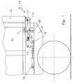
- FIG. 1 and 2 show a side view of the rear area of a loading area 10 of a vehicle with a container 11 placed thereon.
- the container 11 has a flap 12 on its rear end face. This is attached to the upper end of the container 11, not shown here, and can therefore move in the direction of the double arrow 13.
- the flap 12 At its lower end, the flap 12 has a spar 14 which engages around the nose of a locking element 15 in the closed position of the locking element 14 shown in FIG. 1. The flap 12 is thereby secured against opening.
- the locking element 15 is pivotally mounted on the container 11 about a pivot point D and is connected via an articulated connection 16 to a coupling element 17 which is rotatably mounted on the container 11 and has a downwardly projecting projection.
- connection 16 and the coupling element 17 together form an over dead center tensioner for the locking element 15, so that it cannot open automatically.
- the projection of the coupling element 17 engages in a receptacle 18 of an actuating cylinder 19 for the locking element 15.
- the actuating cylinder 19 is arranged on the loading area 10 of the vehicle and can also be operated from there, in particular from the driver's cab.
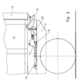
- FIG. 2 now shows the arrangement from FIG. 1 after actuation of the cylinder 19, which leads to a movement of the locking element 15 from the closed position shown in FIG. 1 into the open position leads.
- the flap 12 is now open.
- the receptacle 18 for the projection of the coupling element 17 is moved in the direction of the driver's cab of the vehicle.
- the coupling element 17 pivots and also leads to a pivoting movement of the locking element 15 via the connection 16.
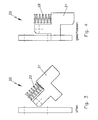
- a mechanical safety device 20 is additionally provided, which is shown in detail in FIGS. 3 and 4.
- the safety device 20 has a swivel body 21 which is acted upon by a spring 22.
- the swivel body 22 In the relaxed state of the spring, the swivel body 22 assumes its closed position shown in FIG. 4. In this position, it prevents the bolt body 15 from pivoting. Only by actuating the actuating cylinder 19 does the pivot body 21 pivot into the open position shown in FIG. 3, in which the spring 22 is compressed. The locking body 15 can now pivot.
- the spring 22 ensures that the swivel body 21 assumes the closed position shown in FIG. 4.
- the locking element 15 is now secured in its closed position. This prevents the flap 12 from opening unintentionally after the container 11 has been lifted off the loading area 10.
Abstract
Description
Die Erfindung betrifft eine Verschlussvorrichtung für an einer Stirnseite von auf der Ladefläche eines Fahrzeugs transportierbaren Containern angeordneten Klappen oder Türen mit mindestens einem am Container angeordneten, zwischen einer Öffnungs- und einer Schließstellung bewegbaren Riegelelement, das in der Schließstellung ein Öffnen der Klappe oder der Türen verhindert.The invention relates to a locking device for flaps or doors arranged on a front side of containers that can be transported on the loading surface of a vehicle, with at least one locking element arranged on the container and movable between an open and a closed position, which prevents the flap or the doors from opening in the closed position ,
Solche Verschlussvorrichtungen sind bereits bekannt. Die Riegelelemente werden dabei von am Container selbst angeordneten Ratschen geöffnet und geschlossen. Die Ratschen werden dabei von Hand betätigt, was bedeutet, dass der Fahrer des Fahrzeugs mit dem Container zum Öffnen der Klappe oder der Türen aussteigen muss. Dies ist Zeit raubend und bei entsprechender Witterung für den Fahrer auch nicht sehr angenehm.Such closure devices are already known. The locking elements are opened and closed by ratchets arranged on the container itself. The ratchets are operated by hand, which means that the driver of the vehicle with the container has to get out to open the flap or the doors. This is time-consuming and, when the weather is good, is not very pleasant for the driver.
Der vorliegenden Erfindung liegt die Aufgabe zugrunde, eine Verschlussvorrichtung für Klappen oder Türen an Containern zu schaffen, die vom Fahrzeug aus zu öffnen sind.The present invention has for its object to provide a closure device for flaps or doors on containers that can be opened from the vehicle.
Die Aufgabe wird mit einer Verschlussvorrichtung der eingangs genannten Art erfindungsgemäß dadurch gelöst, dass das mindestens eine Riegelelement mit einem an dem Fahrzeug angeordneten Betätigungselement koppelbar ist, mit dem das Riegelelement vom Führerhaus des Fahrzeugs aus mindestens von der Schließin die Öffnungsstellung bewegbar ist.The object is achieved according to the invention with a locking device of the type mentioned at the outset in that the at least one locking element can be coupled to an actuating element arranged on the vehicle, with which the locking element can be moved from the driver's cab of the vehicle to the open position at least from the closed position.
Durch die erfindungsgemäße Verschlussvorrichtung können Ratschen am Container selbst entfallen. Das Riegelelement des Containers wird durch das am Fahrzeug angeordnete Betätigungselement bewegt. Da dies vom Führerhaus möglich ist, braucht der Fahrer sein Fahrzeug zur Öffnung des Containers nicht mehr zu verlassen.With the closure device according to the invention, ratchets on the container itself can be eliminated. The locking element of the container is moved by the actuating element arranged on the vehicle. Since this is possible from the cab, the driver no longer has to leave his vehicle to open the container.
Die erfindungsgemäße Verschlussvorrichtung eignet sich insbesondere für Container für gepresste Güter, wie beispielsweise gepressten Abfall. Ist am Container eine Klappe angeordnet, so wird diese vom gepressten Gut nach Öffnen des Riegelelements auswärts gedrückt. Der Container kann dann entladen werden. Dies wird in aller Regel durch eine Schrägstellung des Containers unterstützt.The closure device according to the invention is particularly suitable for containers for pressed goods, such as pressed waste. If a flap is arranged on the container, it is pressed outwards by the pressed material after opening the locking element. The container can then be unloaded. This is usually supported by tilting the container.
Besonders vorteilhaft ist es, wenn durch das Betätigungselement das Riegelelement nach Entleeren des Containers auch wieder in seine Schließstellung bewegbar ist.It is particularly advantageous if, after the container has been emptied, the locking element can also be moved back into its closed position by the actuating element.
Für die Ausgestaltung des Betätigungselements kommen mehrere Möglichkeiten in Betracht. In einer bevorzugten Ausführungsform weist das Betätigungselement einen Hydraulik- oder Pneumatikzylinder auf.There are several options for the design of the actuating element. In a preferred embodiment, the actuating element has a hydraulic or pneumatic cylinder.
Außerdem kann das Betätigungselement eine Aufnahme für einen im unteren Bereich des Containers angeordneten und mit dem Riegelelement verbundenes Verschlusselement mit einem Vorsprung aufweisen. Der Vorsprung kann beim Aufsetzen des Containers auf die Ladefläche in die Aufnahme eingreifen. Bei einer solchen Ausgestaltung der Verschlussvorrichtung geschieht also die Koppelung des Riegelelements mit dem Betätigungselement automatisch beim Aufsetzen des Containers auf die Ladefläche.In addition, the actuating element can have a receptacle for a closure element with a projection which is arranged in the lower region of the container and is connected to the locking element. The lead can be put on the container reach into the receptacle on the loading area. With such a configuration of the closure device, the coupling of the locking element to the actuating element is thus done automatically when the container is placed on the loading surface.
Weitere Vorteile ergeben sich, wenn das Koppelelement Teil eines mit dem mindestens einen Riegelelement verbundenen Übertotpunktspanners ist. Diese Art von Spannern ist besonders sicher. Sie können sich nicht selbsttätig öffnen. Besonders einfach lässt sich ein solcher Übertotpunktspanner realisieren, wenn das mindestens eine Riegelelement schwenkbar am Container angeordnet ist. Selbstverständlich ist aber auch eine verschiebbare oder anderweitig bewegbare Anordnung des Riegelelements möglich.Further advantages are obtained if the coupling element is part of an over-center-point tensioner connected to the at least one locking element. This type of tensioner is particularly safe. You cannot open yourself. Such a dead center tensioner can be realized particularly easily if the at least one locking element is arranged pivotably on the container. Of course, a displaceable or otherwise movable arrangement of the locking element is also possible.
Zur Erhöhung der Sicherheit kann außerdem eine mechanische, die Bewegung des mindestens einen Riegelelements von der Schließ- in die Öffnungsstellung beim Anheben des Containers von der Ladefläche blockierende Sicherheitseinrichtung vorgesehen sein. Damit ist sichergestellt, dass die Klappe oder die Türen des Containers stets geschlossen sind, wenn dieser von der Ladefläche des Fahrzeugs abgehoben wird.To increase safety, a mechanical safety device blocking the movement of the at least one locking element from the closed position into the open position when the container is lifted off the loading area can also be provided. This ensures that the flap or the doors of the container are always closed when it is lifted from the loading area of the vehicle.
Nachfolgend wird ein bevorzugtes Ausführungsbeispiel einer erfindungsgemäßen Verschlussvorrichtung anhand der Zeichnung näher erläutert.A preferred exemplary embodiment of a closure device according to the invention is explained in more detail below with reference to the drawing.
Es zeigen:
- Fig. 1
- eine schematische Seitenansicht des hinteren Endes eines LKW's mit aufgesetztem Container und einer erfindungsgemäßen Verschlussvorrichtung in geschlossenem Zustand;
- Fig. 2
- eine der Fig. 1 entsprechende Ansicht mit geöffneter Verschlussvorrichtung;
- Fig. 3
- eine Detailansicht der Sicherheitseinrichtung der Verschlussvorrichtung aus den Fig. 1 und 2 in geöffnetem Zustand;
- Fig. 4
- eine Ansicht der Sicherheitseinrichtung aus Fig. 3 in geschlossenem Zustand.
- Fig. 1
- a schematic side view of the rear end of a truck with an attached container and a closure device according to the invention in the closed state;
- Fig. 2
- a view corresponding to Figure 1 with the closure device open;
- Fig. 3
- a detailed view of the security device of the closure device of Figures 1 and 2 in the open state.
- Fig. 4
- a view of the safety device of FIG. 3 in the closed state.
Die Fig. 1 und 2 zeigen in der Seitenansicht den hinteren Bereich einer Ladefläche 10 eines Fahrzeugs mit einem darauf abgesetzten Container 11. Der Container 11 weist an seiner hinteren Stirnseite eine Klappe 12 auf. Diese ist am hier nicht dargestellten oberen Ende des Containers 11 angeschlagen und kann sich also in Richtung des Doppelpfeils 13 bewegen. An ihrem unteren Ende weist die Klappe 12 einen Holm 14 auf, den die Nase eines Riegelelements 15 in der in Fig. 1 gezeigten Schließstellung des Riegelelements 14 umgreift. Die Klappe 12 ist dadurch gegen ein Öffnen gesichert. Das Riegelelement 15 ist um einen Drehpunkt D schwenkbar am Container 11 gelagert und über eine gelenkige Verbindung 16 mit einem drehbar am Container 11 gelagerten Koppelelement 17 mit einem nach unten ragenden Vorsprung verbunden. Die Verbindung 16 und das Koppelelement 17 bilden zusammen einen Übertotpunktspanner für das Riegelelement 15, sodass sich dieses nicht selbsttätig öffnen kann. Der Vorsprung des Koppelelements 17 greift in eine Aufnahme 18 eines Betätigungszylinders 19 für das Riegelelement 15 ein. Der Betätigungszylinder 19 ist dabei an der Ladefläche 10 des Fahrzeugs angeordnet und kann auch von diesem aus, insbesondere vom Führerhaus aus, bedient werden.1 and 2 show a side view of the rear area of a
Fig. 2 zeigt nun die Anordnung aus Fig. 1 nach der Betätigung des Zylinders 19, die zu einer Bewegung des Riegelelements 15 von der in Fig. 1 gezeigten Schließstellung in die Öffnungsstellung führt. Die Klappe 12 ist somit jetzt geöffnet. Durch die Betätigung des Betätigungszylinders 19 wird die Aufnahme 18 für den Vorsprung des Koppelelements 17 in Richtung Führerhaus des Fahrzeugs bewegt. Dadurch verschwenkt das Koppelelement 17 und führt über die Verbindung 16 auch zu einer Schwenkbewegung des Riegelelements 15.FIG. 2 now shows the arrangement from FIG. 1 after actuation of the
Zur Verhinderung eines unbeabsichtigten Öffnens des Riegelelements 15 beim Anheben des Containers 11 von der Ladefläche 10 ist zusätzlich eine mechanische Sicherheitseinrichtung 20 vorgesehen, die in den Fig. 3 und 4 im Detail dargestellt ist. Die Sicherheitseinrichtung 20 weist einen Schwenkkörper 21 auf, der durch eine Feder 22 beaufschlagt ist. Im entspannten Zustand der Feder nimmt der Schwenkkörper 22 seine in Fig. 4 dargestellte Schließstellung ein. In dieser Stellung verhindert er ein Verschwenken des Riegelkörpers 15. Nur durch ein Betätigen des Betätigungszylinders 19 verschwenkt der Schwenkkörper 21 in die in Fig. 3 gezeigte Öffnungsstellung, bei der die Feder 22 komprimiert wird. Der Riegelkörper 15 kann jetzt verschwenken. Sobald jedoch das Koppelelement 17 aus der Aufnahme 18 beim Anheben des Containers 11 von der Ladefläche 10 entfernt wird, sorgt die Feder 22 dafür, dass der Schwenkkörper 21 die in Fig. 4 gezeigte Schließstellung einnimmt. Das Riegelelement 15 ist nun in seiner Schließstellung gesichert. Damit wird verhindert, dass sich die Klappe 12 nach Anheben des Containers 11 von der Ladefläche 10 unbeabsichtigt öffnen kann.To prevent unintentional opening of the
Claims (8)
Applications Claiming Priority (2)
| Application Number | Priority Date | Filing Date | Title |
|---|---|---|---|
| DE20304559U DE20304559U1 (en) | 2003-03-21 | 2003-03-21 | closure device |
| DE20304559U | 2003-03-21 |
Publications (1)
| Publication Number | Publication Date |
|---|---|
| EP1460218A2 true EP1460218A2 (en) | 2004-09-22 |
Family
ID=7981002
Family Applications (1)
| Application Number | Title | Priority Date | Filing Date |
|---|---|---|---|
| EP20040006311 Withdrawn EP1460218A2 (en) | 2003-03-21 | 2004-03-17 | Closing device |
Country Status (2)
| Country | Link |
|---|---|
| EP (1) | EP1460218A2 (en) |
| DE (1) | DE20304559U1 (en) |
Cited By (10)
| Publication number | Priority date | Publication date | Assignee | Title |
|---|---|---|---|---|
| DE202008012410U1 (en) * | 2008-09-19 | 2010-02-11 | Gebr. Bode Gmbh & Co. Kg | Rotary latch with over-center locking |
| LT5832B (en) | 2011-09-07 | 2012-05-25 | Uab "Argo Ekspresas" | Safe lower automatic lock and upper improved lock constructions for locking of cargo container's doors and for securing from deformations, and lower automatic lock construction handling method |
| CN101992909B (en) * | 2009-08-26 | 2012-07-25 | 中国国际海运集装箱(集团)股份有限公司 | Container |
| GB2507245A (en) * | 2012-07-23 | 2014-04-30 | George Robert Boden | Tailgate locking system |
| CN104803132A (en) * | 2014-12-03 | 2015-07-29 | 中集集团集装箱控股有限公司 | Locking mechanism and open top container comprising locking mechanism |
| CN105253050A (en) * | 2015-11-05 | 2016-01-20 | 湖南汽车制造有限责任公司 | Locking device and dumper provided with locking device |
| ES2584453A1 (en) * | 2015-03-24 | 2016-09-27 | Ricardo ALONSO PÉREZ | Mechanical opening mechanism for open box tilting containers (Machine-translation by Google Translate, not legally binding) |
| DE202015105380U1 (en) | 2015-10-12 | 2017-01-13 | Ulrich Humbaur | Latch device for pendulum liftboard |
| CN106437362A (en) * | 2015-08-12 | 2017-02-22 | 谢亚群 | Windproof hook for rear doors of refrigerator car |
| CN114000782A (en) * | 2021-10-20 | 2022-02-01 | 浙江生波智能装备有限公司 | Locking device and vacuum coating equipment |
Families Citing this family (6)
| Publication number | Priority date | Publication date | Assignee | Title |
|---|---|---|---|---|
| PL204873B1 (en) * | 2005-12-15 | 2010-02-26 | Wagony & Sacute Widnica Spo & | Mechanism of the hinged unloading traps in railway wagons |
| FR2989956B1 (en) * | 2012-04-26 | 2014-05-09 | Gyrax | ARRANGEMENT FOR MANEUVERING AND LATCHING IN THE POSITION OF A BUNK DOOR |
| CN102889027B (en) * | 2012-10-31 | 2014-10-29 | 常熟华东汽车有限公司 | Side door locking mechanism of double-flap open type carriage |
| CN103910154B (en) * | 2012-12-31 | 2016-09-07 | 南通中集特种运输设备制造有限公司 | Lock, have container and the open method thereof of end lock at the bottom of container |
| CN104071065B (en) * | 2014-05-20 | 2017-04-12 | 赵永胜 | Combined pneumatic unlocking device |
| CN113682673A (en) * | 2021-07-16 | 2021-11-23 | 扬州通利冷藏集装箱有限公司 | Door lock structure of container and container |
-
2003
- 2003-03-21 DE DE20304559U patent/DE20304559U1/en not_active Expired - Lifetime
-
2004
- 2004-03-17 EP EP20040006311 patent/EP1460218A2/en not_active Withdrawn
Cited By (14)
| Publication number | Priority date | Publication date | Assignee | Title |
|---|---|---|---|---|
| DE202008012410U1 (en) * | 2008-09-19 | 2010-02-11 | Gebr. Bode Gmbh & Co. Kg | Rotary latch with over-center locking |
| CN101992909B (en) * | 2009-08-26 | 2012-07-25 | 中国国际海运集装箱(集团)股份有限公司 | Container |
| LT5832B (en) | 2011-09-07 | 2012-05-25 | Uab "Argo Ekspresas" | Safe lower automatic lock and upper improved lock constructions for locking of cargo container's doors and for securing from deformations, and lower automatic lock construction handling method |
| EP2567911A1 (en) | 2011-09-07 | 2013-03-13 | UAB "Argo Ekspresas" | Cargo container with a doors locking mechanism and method of closing the doors of such a container |
| GB2507245A (en) * | 2012-07-23 | 2014-04-30 | George Robert Boden | Tailgate locking system |
| GB2507245B (en) * | 2012-07-23 | 2014-12-10 | George Robert Boden | Tailgate locking system |
| CN104803132A (en) * | 2014-12-03 | 2015-07-29 | 中集集团集装箱控股有限公司 | Locking mechanism and open top container comprising locking mechanism |
| CN104803132B (en) * | 2014-12-03 | 2017-10-03 | 中集集团集装箱控股有限公司 | Retaining mechanism and the hard open top container with it |
| ES2584453A1 (en) * | 2015-03-24 | 2016-09-27 | Ricardo ALONSO PÉREZ | Mechanical opening mechanism for open box tilting containers (Machine-translation by Google Translate, not legally binding) |
| CN106437362A (en) * | 2015-08-12 | 2017-02-22 | 谢亚群 | Windproof hook for rear doors of refrigerator car |
| DE202015105380U1 (en) | 2015-10-12 | 2017-01-13 | Ulrich Humbaur | Latch device for pendulum liftboard |
| CN105253050A (en) * | 2015-11-05 | 2016-01-20 | 湖南汽车制造有限责任公司 | Locking device and dumper provided with locking device |
| CN105253050B (en) * | 2015-11-05 | 2018-01-19 | 湖南汽车制造有限责任公司 | Locking device and the dumper for being equiped with the locking device |
| CN114000782A (en) * | 2021-10-20 | 2022-02-01 | 浙江生波智能装备有限公司 | Locking device and vacuum coating equipment |
Also Published As
| Publication number | Publication date |
|---|---|
| DE20304559U1 (en) | 2003-06-26 |
Similar Documents
| Publication | Publication Date | Title |
|---|---|---|
| EP1460218A2 (en) | Closing device | |
| DE112010000872B4 (en) | Container | |
| EP0801013B1 (en) | Refuse collection receptacle and vehicle to take up it | |
| WO2003086801A1 (en) | Blocking device for a vehicle roof which can be moved between a closed position and a stored position | |
| DE2043780C3 (en) | Interior locking device for a motor vehicle door lock | |
| EP0260436B1 (en) | Closing device for loading or unloading openings of transport tanks, especially for tank or hopper vehicles | |
| DE2048373A1 (en) | Movable vehicle roof | |
| DE4441551C1 (en) | Device for lifting and emptying containers for recycling materials | |
| EP1785304A1 (en) | Vehicle with a vehicle roof adjustable between a closed position and a stored position | |
| DE19812835B4 (en) | Fanghook actuator assembly for engine hoods of motor vehicles | |
| DE3517491C2 (en) | ||
| DE1199955B (en) | Vehicle lifting platform | |
| DE102010003932A1 (en) | Covering device for load transport container i.e. dump basket, of load transport vehicle i.e. dump truck vehicle, has folding bracket coupled with operating unit such that folding clip switches pivoting movement of rear plate | |
| DE4321538A1 (en) | Loading appliance for bulk-material containers | |
| DE2317553C2 (en) | Device for opening the lid when emptying containers, for example garbage cans | |
| DE19958746A1 (en) | Swinging vehicle door which opens to a position flat against the vehicle side wall | |
| DE4130720C2 (en) | Self-loading wagon | |
| EP1847447B1 (en) | Posts for the loading aperture of a vehicle superstructure | |
| DE2156572A1 (en) | DEVICE FOR LOCKING A CHANGE CONTAINER WITH A MUELL PRESS | |
| DE3048652A1 (en) | "MANUAL OPERATING ARRANGEMENT FOR CARGO CHARGING SYSTEMS" | |
| DE4126526C2 (en) | Label dispenser | |
| DE927007C (en) | Actuating device for the closing valve of pressure medium containers, in particular of extinguishing medium containers | |
| DE202005012674U1 (en) | Toy refuse collecting truck has a crank operated drive for a hinged grab arm to lift and tip toy bins into the top of the vehicle | |
| EP0561168A1 (en) | Closure mechanism | |
| DE4315505C2 (en) | Device for opening a lid, especially for a lying garbage container |
Legal Events
| Date | Code | Title | Description |
|---|---|---|---|
| PUAI | Public reference made under article 153(3) epc to a published international application that has entered the european phase |
Free format text: ORIGINAL CODE: 0009012 |
|
| AK | Designated contracting states |
Kind code of ref document: A2 Designated state(s): AT BE BG CH CY CZ DE DK EE ES FI FR GB GR HU IE IT LI LU MC NL PL PT RO SE SI SK TR |
|
| AX | Request for extension of the european patent |
Extension state: AL LT LV MK |
|
| STAA | Information on the status of an ep patent application or granted ep patent |
Free format text: STATUS: THE APPLICATION IS DEEMED TO BE WITHDRAWN |
|
| 18D | Application deemed to be withdrawn |
Effective date: 20061002 |