EP1458984B1 - Appareil servant au transport de fluides et plaque d'assise a cet effet - Google Patents
Appareil servant au transport de fluides et plaque d'assise a cet effet Download PDFInfo
- Publication number
- EP1458984B1 EP1458984B1 EP02787021A EP02787021A EP1458984B1 EP 1458984 B1 EP1458984 B1 EP 1458984B1 EP 02787021 A EP02787021 A EP 02787021A EP 02787021 A EP02787021 A EP 02787021A EP 1458984 B1 EP1458984 B1 EP 1458984B1
- Authority
- EP
- European Patent Office
- Prior art keywords
- base plate
- fluidic element
- fluidic
- fluid
- outlet
- Prior art date
- Legal status (The legal status is an assumption and is not a legal conclusion. Google has not performed a legal analysis and makes no representation as to the accuracy of the status listed.)
- Expired - Fee Related
Links
Images

Classifications
-
- F—MECHANICAL ENGINEERING; LIGHTING; HEATING; WEAPONS; BLASTING
- F16—ENGINEERING ELEMENTS AND UNITS; GENERAL MEASURES FOR PRODUCING AND MAINTAINING EFFECTIVE FUNCTIONING OF MACHINES OR INSTALLATIONS; THERMAL INSULATION IN GENERAL
- F16K—VALVES; TAPS; COCKS; ACTUATING-FLOATS; DEVICES FOR VENTING OR AERATING
- F16K27/00—Construction of housing; Use of materials therefor
- F16K27/003—Housing formed from a plurality of the same valve elements
-
- Y—GENERAL TAGGING OF NEW TECHNOLOGICAL DEVELOPMENTS; GENERAL TAGGING OF CROSS-SECTIONAL TECHNOLOGIES SPANNING OVER SEVERAL SECTIONS OF THE IPC; TECHNICAL SUBJECTS COVERED BY FORMER USPC CROSS-REFERENCE ART COLLECTIONS [XRACs] AND DIGESTS
- Y10—TECHNICAL SUBJECTS COVERED BY FORMER USPC
- Y10T—TECHNICAL SUBJECTS COVERED BY FORMER US CLASSIFICATION
- Y10T137/00—Fluid handling
- Y10T137/0318—Processes
- Y10T137/0402—Cleaning, repairing, or assembling
- Y10T137/0441—Repairing, securing, replacing, or servicing pipe joint, valve, or tank
- Y10T137/0452—Detecting or repairing leak
-
- Y—GENERAL TAGGING OF NEW TECHNOLOGICAL DEVELOPMENTS; GENERAL TAGGING OF CROSS-SECTIONAL TECHNOLOGIES SPANNING OVER SEVERAL SECTIONS OF THE IPC; TECHNICAL SUBJECTS COVERED BY FORMER USPC CROSS-REFERENCE ART COLLECTIONS [XRACs] AND DIGESTS
- Y10—TECHNICAL SUBJECTS COVERED BY FORMER USPC
- Y10T—TECHNICAL SUBJECTS COVERED BY FORMER US CLASSIFICATION
- Y10T137/00—Fluid handling
- Y10T137/8593—Systems
- Y10T137/877—With flow control means for branched passages
- Y10T137/87885—Sectional block structure
Definitions
- the present invention generally relates to an apparatus for conveying at least one fluid, and more particularly to an apparatus for conveying at least one fluid, comprising at least a first fluidic element and a second fluidic element connected to each other for conveying said fluid, and a base plate to which said first fluidic element and said second fluidic element are mounted.
- the present invention further relates to a base plate, and more particularly to a base plate for mounting at least a first fluidic element and a second fluidic element connectable to each other for conveying a fluid.
- gas panels comprising a plurality of fluidic elements for distributing gases that are for example necessary for chemical vapor deposition processes, etching processes, or diffusion processes.
- the fluidic elements may for example be manual valves, regulators, filters, transducers, air operated valves, purge blocks, mass flow controllers, and base blocks.
- Said base blocks are generally used for connecting other fluidic elements.
- the replacing of a faulty fluidic element requires as a safety precaution that the gas panel is checked for leaks.
- Document D1 (US 3,871,209) describes a method of externally testing connections between tubular members.
- Document D2 (JP 2000 028470) describes a device and method for inspecting gas leakage in a process gas supplying unit
- the present invention seeks to solve this problem by improving the above mentioned apparatus and the above mentioned base plate.
- an apparatus for conveying at least one fluid comprising at least a first fluidic element 10 and a second fluidic element 30 connected to each other for conveying said fluid, according to the disclosure of claim 1.
- fluid stands for any liquid and/or gas.
- fluid element stands for any element suitable for transporting and/or affecting any fluid.
- the leak test agent is helium.
- Figure 1 shows a top view of a gas stick formed by a plurality of fluidic elements
- Figure 2 shows an embodiment of the apparatus in accordance with the present invention, wherein the apparatus is formed by the gas stick of figure 1 (shown in a side view) mounted on a base plate in accordance with the present invention.
- potential leaks are denoted by a plurality of arrows.
- the gas stick shown in Figure 1 and Figure 2 comprises the following fluidic elements: a hand valve 10, a filter 12, a regulator 14, a transducer 16, an air operated valve 18 comprising a check valve, a mass flow controller 20, an air operated valve 22 comprising a check valve, an outlet 28 (the inlet 26 is integrally formed with the hand valve 10), and a plurality of base blocks 30 through 42.
- the base blocks 30 through 42 preferably comprise V-shaped channels or pipes enabling a fluid flow from one fluidic element mounted on a respective base block to an adjacent fluidic element mounted on the same base block.
- the base blocks 30 through 42 are mounted to a base plate 24. In this base plate 24 there is formed a plurality of pipes for feeding a suitable leak test agent to potential leaks.
- This pipe 48 comprises an outlet 46 for feeding an leak test agent to the connection area of the hand valve 10, base block 30 and the filter 12.
- the pipe 48 further comprises an inlet 44 located at the border 54 of the base plate 24.
- An alternative to the latter is to provide a single pipe with a plurality of outlets that are individually closeable for example by valves.
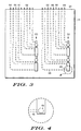
- FIG 3 shows an embodiment of a base plate in accordance with the present invention and Figure 4 is a detail view of the area 4 of Figure 3.
- lines 50, 52 of a plurality of fluidic elements on the base plate 24 there are mounted to lines 50, 52 of a plurality of fluidic elements on the base plate 24.
- Each dashed line denotes a pipe formed in the base plate 24.
- the base plate 24 comprises a laminate structure the pipes may be formed integrally with the base plate 24.
- Each pipe comprises an inlet 44 at the border 54 of the base plate 24.
- the pipe 48 is provided with a numeral.
- the pipe 48 comprises an outlet 46 of circular shape.
- the outlet 46 (and also the outlets of the other pipes) is located close to a potential leak, especially close to the connection area of two fluidic elements.
- the invention is particularly useful if two or more lines 50, 52 of fluidic elements are arranged close to each other since in this case it is very difficult to feed an leak test agent from the top to potential leaks.
Claims (11)
- Appareil servant à l'acheminement d'au moins un fluide, comprenant au moins un premier élément fluidique (10) et un second élément fluidique (30) reliés l'un à l'autre pour acheminer ledit fluide, et une plaque de base (24) sur laquelle sont montés ledit premier élément fluidique (10) et ledit second élément fluidique (30),
caractérisé en ce que ladite plaque de base (24) comprend une pluralité de tuyaux (48), chacun ayant une sortie (46) pour amener un agent de test d'étanchéité vers une zone de liaison entre les éléments fluidiques adjacents (10, 30), dans lequel chacun desdits tuyaux comprend une entrée (44), et dans lequel lesdites entrées sont agencées au niveau d'une bordure de ladite plaque de base (24). - Appareil selon la revendication 1, dans lequel ledit agent de test d'étanchéité comprend de l'hélium.
- Appareil selon la revendication 1, dans lequel ledit appareil est un écran à plasma.
- Appareil selon la revendication 1, dans lequel ladite sortie (46) est la sortie d'un tuyau (48) disposé dans ladite plaque de base (24).
- Appareil selon la revendication 1, dans lequel ladite plaque de base comprend au moins partiellement une structure laminée.
- Appareil selon la revendication 1, dans lequel une pluralité d'éléments fluidiques (10-22, 30-42) sont agencés selon des lignes, et lesdites lignes sont agencées de manière adjacente les unes aux autres.
- Appareil selon la revendication 1, dans lequel le premier élément fluidique (10, 18, 22) est une soupape.
- Appareil selon la revendication 1, dans lequel le premier élément fluidique est un filtre (12).
- Appareil selon la revendication 1, dans lequel le premier élément fluidique est un régulateur de pression (14).
- Appareil selon la revendication 1, dans lequel le premier élément fluidique est un transducteur de pression (16).
- Appareil selon la revendication 1, dans lequel le premier élément fluidique est un dispositif de contrôle de débit massique (20).
Applications Claiming Priority (3)
| Application Number | Priority Date | Filing Date | Title |
|---|---|---|---|
| US10/027,545 US6634385B2 (en) | 2001-12-21 | 2001-12-21 | Apparatus for conveying fluids and base plate |
| US27545 | 2001-12-21 | ||
| PCT/US2002/039700 WO2003056189A1 (fr) | 2001-12-21 | 2002-12-12 | Appareil servant au transport de fluides et plaque d'assise a cet effet |
Publications (2)
| Publication Number | Publication Date |
|---|---|
| EP1458984A1 EP1458984A1 (fr) | 2004-09-22 |
| EP1458984B1 true EP1458984B1 (fr) | 2006-07-05 |
Family
ID=21838340
Family Applications (1)
| Application Number | Title | Priority Date | Filing Date |
|---|---|---|---|
| EP02787021A Expired - Fee Related EP1458984B1 (fr) | 2001-12-21 | 2002-12-12 | Appareil servant au transport de fluides et plaque d'assise a cet effet |
Country Status (6)
| Country | Link |
|---|---|
| US (1) | US6634385B2 (fr) |
| EP (1) | EP1458984B1 (fr) |
| JP (1) | JP4663235B2 (fr) |
| AU (1) | AU2002351364A1 (fr) |
| DE (1) | DE60213001T2 (fr) |
| WO (1) | WO2003056189A1 (fr) |
Families Citing this family (10)
| Publication number | Priority date | Publication date | Assignee | Title |
|---|---|---|---|---|
| US7334605B2 (en) * | 2002-08-27 | 2008-02-26 | Celerity, Inc. | Modular substrate gas panel having manifold connections in a common plane |
| US7370674B2 (en) * | 2004-02-20 | 2008-05-13 | Michael Doyle | Modular fluid distribution system |
| US20070023084A1 (en) * | 2005-07-28 | 2007-02-01 | Cimberio Valve Co. Inc. | Valve module for a fluid-distribution system |
| JP2007152211A (ja) * | 2005-12-02 | 2007-06-21 | Asahi Organic Chem Ind Co Ltd | フラッシング装置 |
| US7575616B2 (en) * | 2006-02-10 | 2009-08-18 | Entegris, Inc. | Low-profile surface mount filter |
| US20080302426A1 (en) * | 2007-06-06 | 2008-12-11 | Greg Patrick Mulligan | System and method of securing removable components for distribution of fluids |
| US7784496B2 (en) * | 2007-06-11 | 2010-08-31 | Lam Research Corporation | Triple valve inlet assembly |
| US8307854B1 (en) | 2009-05-14 | 2012-11-13 | Vistadeltek, Inc. | Fluid delivery substrates for building removable standard fluid delivery sticks |
| CN102804335B (zh) | 2009-06-10 | 2015-10-21 | 威斯塔德尔特有限责任公司 | 极限流速和/或高温流体递送基体 |
| US8464818B2 (en) * | 2009-07-21 | 2013-06-18 | Toyota Jidosha Kabushiki Kaisha | Fuel system and vehicle |
Family Cites Families (13)
| Publication number | Priority date | Publication date | Assignee | Title |
|---|---|---|---|---|
| US3871209A (en) | 1971-03-25 | 1975-03-18 | Malvern M Hasha | Method of externally testing connections between tubular members |
| CH558514A (de) * | 1972-11-28 | 1975-01-31 | Sulzer Ag | Vorrichtung zum durchfuehren eines rohrbuendels durch eine behaelterwand. |
| US3895831A (en) * | 1973-05-10 | 1975-07-22 | Conax Corp | Seal assembly providing dual seal zones |
| US4817994A (en) * | 1987-10-14 | 1989-04-04 | Bronnert Herve X | Aseptic pipe joint |
| JPH02261983A (ja) * | 1989-03-31 | 1990-10-24 | Ishikawajima Harima Heavy Ind Co Ltd | サイクル式分配弁 |
| DE4134489A1 (de) | 1991-03-28 | 1992-10-01 | Weatherford Prod & Equip | Einrichtung zum pruefen der gasdichtigkeit von loesbaren hohlkoerperverbindungen |
| US6293310B1 (en) * | 1996-10-30 | 2001-09-25 | Unit Instruments, Inc. | Gas panel |
| JP3997337B2 (ja) * | 1996-11-20 | 2007-10-24 | 忠弘 大見 | 流体制御装置 |
| US6302141B1 (en) * | 1996-12-03 | 2001-10-16 | Insync Systems, Inc. | Building blocks for integrated gas panel |
| US6068016A (en) * | 1997-09-25 | 2000-05-30 | Applied Materials, Inc | Modular fluid flow system with integrated pump-purge |
| WO1999064771A1 (fr) * | 1998-06-12 | 1999-12-16 | Hollingshead J Gregory | Blocs modulaires unifies de distribution de produits chimiques |
| JP3626014B2 (ja) | 1998-07-09 | 2005-03-02 | シーケーディ株式会社 | プロセスガス供給ユニットにおけるガス漏れ検査装置及びガス漏れ検査方法 |
| US6026843A (en) | 1998-11-24 | 2000-02-22 | The Boc Group, Inc. | Valve box manifold system and distribution method |
-
2001
- 2001-12-21 US US10/027,545 patent/US6634385B2/en not_active Expired - Fee Related
-
2002
- 2002-12-12 AU AU2002351364A patent/AU2002351364A1/en not_active Abandoned
- 2002-12-12 JP JP2003556683A patent/JP4663235B2/ja not_active Expired - Fee Related
- 2002-12-12 WO PCT/US2002/039700 patent/WO2003056189A1/fr active IP Right Grant
- 2002-12-12 DE DE60213001T patent/DE60213001T2/de not_active Expired - Fee Related
- 2002-12-12 EP EP02787021A patent/EP1458984B1/fr not_active Expired - Fee Related
Also Published As
| Publication number | Publication date |
|---|---|
| JP4663235B2 (ja) | 2011-04-06 |
| DE60213001T2 (de) | 2006-11-23 |
| US6634385B2 (en) | 2003-10-21 |
| AU2002351364A1 (en) | 2003-07-15 |
| WO2003056189A1 (fr) | 2003-07-10 |
| DE60213001D1 (de) | 2006-08-17 |
| EP1458984A1 (fr) | 2004-09-22 |
| JP2005514561A (ja) | 2005-05-19 |
| US20030116207A1 (en) | 2003-06-26 |
Similar Documents
| Publication | Publication Date | Title |
|---|---|---|
| US7055550B2 (en) | Fluid delivery system and mounting panel therefor | |
| US8322380B2 (en) | Universal fluid flow adaptor | |
| US7370674B2 (en) | Modular fluid distribution system | |
| KR101476446B1 (ko) | 일체화된 가스 시스템 가스 패널을 위한 적응성 매니폴드 | |
| KR101321793B1 (ko) | 유체 기기 유닛 구조 | |
| US5836355A (en) | Building blocks for integrated gas panel | |
| US8950433B2 (en) | Manifold system for gas and fluid delivery | |
| US8307854B1 (en) | Fluid delivery substrates for building removable standard fluid delivery sticks | |
| JP2002349797A (ja) | 流体制御装置 | |
| EP1458984B1 (fr) | Appareil servant au transport de fluides et plaque d'assise a cet effet | |
| KR100990695B1 (ko) | 가스공급유닛 및 가스공급시스템 | |
| JP6211584B2 (ja) | プラズマ処理システムにおける共有ガスパネル | |
| US7784497B2 (en) | MSM component and associated gas panel assembly | |
| US7458397B2 (en) | Modular fluid distribution system | |
| US7784496B2 (en) | Triple valve inlet assembly | |
| JP3871438B2 (ja) | プロセスガス供給ユニット | |
| JP2006234110A (ja) | ガス供給ユニット及びガス供給システム | |
| WO2005008107A2 (fr) | Systeme modulaire de distribution de fluides | |
| CN111945136B (zh) | 半导体工艺设备及其集成供气系统 | |
| JP2006242222A (ja) | 集積化ガス制御装置と集積化ガス制御方法 |
Legal Events
| Date | Code | Title | Description |
|---|---|---|---|
| PUAI | Public reference made under article 153(3) epc to a published international application that has entered the european phase |
Free format text: ORIGINAL CODE: 0009012 |
|
| 17P | Request for examination filed |
Effective date: 20040708 |
|
| AK | Designated contracting states |
Kind code of ref document: A1 Designated state(s): AT BE BG CH CY CZ DE DK EE ES FI FR GB GR IE IT LI LU MC NL PT SE SI SK TR |
|
| AX | Request for extension of the european patent |
Extension state: AL LT LV MK RO |
|
| RAP1 | Party data changed (applicant data changed or rights of an application transferred) |
Owner name: FREESCALE SEMICONDUCTOR, INC. |
|
| 17Q | First examination report despatched |
Effective date: 20050627 |
|
| GRAP | Despatch of communication of intention to grant a patent |
Free format text: ORIGINAL CODE: EPIDOSNIGR1 |
|
| GRAS | Grant fee paid |
Free format text: ORIGINAL CODE: EPIDOSNIGR3 |
|
| GRAA | (expected) grant |
Free format text: ORIGINAL CODE: 0009210 |
|
| AK | Designated contracting states |
Kind code of ref document: B1 Designated state(s): DE FR GB IT |
|
| REG | Reference to a national code |
Ref country code: GB Ref legal event code: FG4D |
|
| REF | Corresponds to: |
Ref document number: 60213001 Country of ref document: DE Date of ref document: 20060817 Kind code of ref document: P |
|
| PGFP | Annual fee paid to national office [announced via postgrant information from national office to epo] |
Ref country code: GB Payment date: 20061106 Year of fee payment: 5 |
|
| PGFP | Annual fee paid to national office [announced via postgrant information from national office to epo] |
Ref country code: FR Payment date: 20061201 Year of fee payment: 5 |
|
| PGFP | Annual fee paid to national office [announced via postgrant information from national office to epo] |
Ref country code: DE Payment date: 20061229 Year of fee payment: 5 |
|
| PGFP | Annual fee paid to national office [announced via postgrant information from national office to epo] |
Ref country code: IT Payment date: 20061231 Year of fee payment: 5 |
|
| ET | Fr: translation filed | ||
| PLBE | No opposition filed within time limit |
Free format text: ORIGINAL CODE: 0009261 |
|
| STAA | Information on the status of an ep patent application or granted ep patent |
Free format text: STATUS: NO OPPOSITION FILED WITHIN TIME LIMIT |
|
| 26N | No opposition filed |
Effective date: 20070410 |
|
| GBPC | Gb: european patent ceased through non-payment of renewal fee |
Effective date: 20071212 |
|
| PG25 | Lapsed in a contracting state [announced via postgrant information from national office to epo] |
Ref country code: DE Free format text: LAPSE BECAUSE OF NON-PAYMENT OF DUE FEES Effective date: 20080701 |
|
| REG | Reference to a national code |
Ref country code: FR Ref legal event code: ST Effective date: 20081020 |
|
| PG25 | Lapsed in a contracting state [announced via postgrant information from national office to epo] |
Ref country code: GB Free format text: LAPSE BECAUSE OF NON-PAYMENT OF DUE FEES Effective date: 20071212 |
|
| PG25 | Lapsed in a contracting state [announced via postgrant information from national office to epo] |
Ref country code: FR Free format text: LAPSE BECAUSE OF NON-PAYMENT OF DUE FEES Effective date: 20071231 |
|
| PG25 | Lapsed in a contracting state [announced via postgrant information from national office to epo] |
Ref country code: IT Free format text: LAPSE BECAUSE OF NON-PAYMENT OF DUE FEES Effective date: 20071212 |