EP1457916B1 - Automatisch aktivierter, tragbarer Laser-Strichkodeabtaster mit Datenübertragungsvorrichtung - Google Patents
Automatisch aktivierter, tragbarer Laser-Strichkodeabtaster mit Datenübertragungsvorrichtung Download PDFInfo
- Publication number
- EP1457916B1 EP1457916B1 EP04076763A EP04076763A EP1457916B1 EP 1457916 B1 EP1457916 B1 EP 1457916B1 EP 04076763 A EP04076763 A EP 04076763A EP 04076763 A EP04076763 A EP 04076763A EP 1457916 B1 EP1457916 B1 EP 1457916B1
- Authority
- EP
- European Patent Office
- Prior art keywords
- bar code
- code symbol
- data
- automatically
- reading
- Prior art date
- Legal status (The legal status is an assumption and is not a legal conclusion. Google has not performed a legal analysis and makes no representation as to the accuracy of the status listed.)
- Expired - Lifetime
Links
Images


Classifications
-
- G—PHYSICS
- G06—COMPUTING; CALCULATING OR COUNTING
- G06K—GRAPHICAL DATA READING; PRESENTATION OF DATA; RECORD CARRIERS; HANDLING RECORD CARRIERS
- G06K7/00—Methods or arrangements for sensing record carriers, e.g. for reading patterns
- G06K7/10—Methods or arrangements for sensing record carriers, e.g. for reading patterns by electromagnetic radiation, e.g. optical sensing; by corpuscular radiation
-
- B—PERFORMING OPERATIONS; TRANSPORTING
- B82—NANOTECHNOLOGY
- B82Y—SPECIFIC USES OR APPLICATIONS OF NANOSTRUCTURES; MEASUREMENT OR ANALYSIS OF NANOSTRUCTURES; MANUFACTURE OR TREATMENT OF NANOSTRUCTURES
- B82Y15/00—Nanotechnology for interacting, sensing or actuating, e.g. quantum dots as markers in protein assays or molecular motors
-
- G—PHYSICS
- G06—COMPUTING; CALCULATING OR COUNTING
- G06K—GRAPHICAL DATA READING; PRESENTATION OF DATA; RECORD CARRIERS; HANDLING RECORD CARRIERS
- G06K7/00—Methods or arrangements for sensing record carriers, e.g. for reading patterns
- G06K7/10—Methods or arrangements for sensing record carriers, e.g. for reading patterns by electromagnetic radiation, e.g. optical sensing; by corpuscular radiation
- G06K7/10544—Methods or arrangements for sensing record carriers, e.g. for reading patterns by electromagnetic radiation, e.g. optical sensing; by corpuscular radiation by scanning of the records by radiation in the optical part of the electromagnetic spectrum
- G06K7/10554—Moving beam scanning
- G06K7/10564—Light sources
- G06K7/10584—Source control
-
- G—PHYSICS
- G06—COMPUTING; CALCULATING OR COUNTING
- G06K—GRAPHICAL DATA READING; PRESENTATION OF DATA; RECORD CARRIERS; HANDLING RECORD CARRIERS
- G06K7/00—Methods or arrangements for sensing record carriers, e.g. for reading patterns
- G06K7/10—Methods or arrangements for sensing record carriers, e.g. for reading patterns by electromagnetic radiation, e.g. optical sensing; by corpuscular radiation
- G06K7/10544—Methods or arrangements for sensing record carriers, e.g. for reading patterns by electromagnetic radiation, e.g. optical sensing; by corpuscular radiation by scanning of the records by radiation in the optical part of the electromagnetic spectrum
- G06K7/10554—Moving beam scanning
- G06K7/10594—Beam path
- G06K7/10603—Basic scanning using moving elements
- G06K7/10663—Basic scanning using moving elements using hologram
-
- G—PHYSICS
- G06—COMPUTING; CALCULATING OR COUNTING
- G06K—GRAPHICAL DATA READING; PRESENTATION OF DATA; RECORD CARRIERS; HANDLING RECORD CARRIERS
- G06K7/00—Methods or arrangements for sensing record carriers, e.g. for reading patterns
- G06K7/10—Methods or arrangements for sensing record carriers, e.g. for reading patterns by electromagnetic radiation, e.g. optical sensing; by corpuscular radiation
- G06K7/10544—Methods or arrangements for sensing record carriers, e.g. for reading patterns by electromagnetic radiation, e.g. optical sensing; by corpuscular radiation by scanning of the records by radiation in the optical part of the electromagnetic spectrum
- G06K7/10554—Moving beam scanning
- G06K7/10594—Beam path
- G06K7/10603—Basic scanning using moving elements
- G06K7/10673—Parallel lines
-
- G—PHYSICS
- G06—COMPUTING; CALCULATING OR COUNTING
- G06K—GRAPHICAL DATA READING; PRESENTATION OF DATA; RECORD CARRIERS; HANDLING RECORD CARRIERS
- G06K7/00—Methods or arrangements for sensing record carriers, e.g. for reading patterns
- G06K7/10—Methods or arrangements for sensing record carriers, e.g. for reading patterns by electromagnetic radiation, e.g. optical sensing; by corpuscular radiation
- G06K7/10544—Methods or arrangements for sensing record carriers, e.g. for reading patterns by electromagnetic radiation, e.g. optical sensing; by corpuscular radiation by scanning of the records by radiation in the optical part of the electromagnetic spectrum
- G06K7/10554—Moving beam scanning
- G06K7/10594—Beam path
- G06K7/10683—Arrangement of fixed elements
- G06K7/10693—Arrangement of fixed elements for omnidirectional scanning
-
- G—PHYSICS
- G06—COMPUTING; CALCULATING OR COUNTING
- G06K—GRAPHICAL DATA READING; PRESENTATION OF DATA; RECORD CARRIERS; HANDLING RECORD CARRIERS
- G06K7/00—Methods or arrangements for sensing record carriers, e.g. for reading patterns
- G06K7/10—Methods or arrangements for sensing record carriers, e.g. for reading patterns by electromagnetic radiation, e.g. optical sensing; by corpuscular radiation
- G06K7/10544—Methods or arrangements for sensing record carriers, e.g. for reading patterns by electromagnetic radiation, e.g. optical sensing; by corpuscular radiation by scanning of the records by radiation in the optical part of the electromagnetic spectrum
- G06K7/10554—Moving beam scanning
- G06K7/10594—Beam path
- G06K7/10683—Arrangement of fixed elements
- G06K7/10702—Particularities of propagating elements, e.g. lenses, mirrors
-
- G—PHYSICS
- G06—COMPUTING; CALCULATING OR COUNTING
- G06K—GRAPHICAL DATA READING; PRESENTATION OF DATA; RECORD CARRIERS; HANDLING RECORD CARRIERS
- G06K7/00—Methods or arrangements for sensing record carriers, e.g. for reading patterns
- G06K7/10—Methods or arrangements for sensing record carriers, e.g. for reading patterns by electromagnetic radiation, e.g. optical sensing; by corpuscular radiation
- G06K7/10544—Methods or arrangements for sensing record carriers, e.g. for reading patterns by electromagnetic radiation, e.g. optical sensing; by corpuscular radiation by scanning of the records by radiation in the optical part of the electromagnetic spectrum
- G06K7/10792—Special measures in relation to the object to be scanned
- G06K7/10801—Multidistance reading
- G06K7/10811—Focalisation
-
- G—PHYSICS
- G06—COMPUTING; CALCULATING OR COUNTING
- G06K—GRAPHICAL DATA READING; PRESENTATION OF DATA; RECORD CARRIERS; HANDLING RECORD CARRIERS
- G06K7/00—Methods or arrangements for sensing record carriers, e.g. for reading patterns
- G06K7/10—Methods or arrangements for sensing record carriers, e.g. for reading patterns by electromagnetic radiation, e.g. optical sensing; by corpuscular radiation
- G06K7/10544—Methods or arrangements for sensing record carriers, e.g. for reading patterns by electromagnetic radiation, e.g. optical sensing; by corpuscular radiation by scanning of the records by radiation in the optical part of the electromagnetic spectrum
- G06K7/10821—Methods or arrangements for sensing record carriers, e.g. for reading patterns by electromagnetic radiation, e.g. optical sensing; by corpuscular radiation by scanning of the records by radiation in the optical part of the electromagnetic spectrum further details of bar or optical code scanning devices
- G06K7/10851—Circuits for pulse shaping, amplifying, eliminating noise signals, checking the function of the sensing device
-
- G—PHYSICS
- G06—COMPUTING; CALCULATING OR COUNTING
- G06K—GRAPHICAL DATA READING; PRESENTATION OF DATA; RECORD CARRIERS; HANDLING RECORD CARRIERS
- G06K7/00—Methods or arrangements for sensing record carriers, e.g. for reading patterns
- G06K7/10—Methods or arrangements for sensing record carriers, e.g. for reading patterns by electromagnetic radiation, e.g. optical sensing; by corpuscular radiation
- G06K7/10544—Methods or arrangements for sensing record carriers, e.g. for reading patterns by electromagnetic radiation, e.g. optical sensing; by corpuscular radiation by scanning of the records by radiation in the optical part of the electromagnetic spectrum
- G06K7/10821—Methods or arrangements for sensing record carriers, e.g. for reading patterns by electromagnetic radiation, e.g. optical sensing; by corpuscular radiation by scanning of the records by radiation in the optical part of the electromagnetic spectrum further details of bar or optical code scanning devices
- G06K7/10861—Methods or arrangements for sensing record carriers, e.g. for reading patterns by electromagnetic radiation, e.g. optical sensing; by corpuscular radiation by scanning of the records by radiation in the optical part of the electromagnetic spectrum further details of bar or optical code scanning devices sensing of data fields affixed to objects or articles, e.g. coded labels
- G06K7/10871—Methods or arrangements for sensing record carriers, e.g. for reading patterns by electromagnetic radiation, e.g. optical sensing; by corpuscular radiation by scanning of the records by radiation in the optical part of the electromagnetic spectrum further details of bar or optical code scanning devices sensing of data fields affixed to objects or articles, e.g. coded labels randomly oriented data-fields, code-marks therefore, e.g. concentric circles-code
-
- G—PHYSICS
- G06—COMPUTING; CALCULATING OR COUNTING
- G06K—GRAPHICAL DATA READING; PRESENTATION OF DATA; RECORD CARRIERS; HANDLING RECORD CARRIERS
- G06K7/00—Methods or arrangements for sensing record carriers, e.g. for reading patterns
- G06K7/10—Methods or arrangements for sensing record carriers, e.g. for reading patterns by electromagnetic radiation, e.g. optical sensing; by corpuscular radiation
- G06K7/10544—Methods or arrangements for sensing record carriers, e.g. for reading patterns by electromagnetic radiation, e.g. optical sensing; by corpuscular radiation by scanning of the records by radiation in the optical part of the electromagnetic spectrum
- G06K7/10821—Methods or arrangements for sensing record carriers, e.g. for reading patterns by electromagnetic radiation, e.g. optical sensing; by corpuscular radiation by scanning of the records by radiation in the optical part of the electromagnetic spectrum further details of bar or optical code scanning devices
- G06K7/10881—Methods or arrangements for sensing record carriers, e.g. for reading patterns by electromagnetic radiation, e.g. optical sensing; by corpuscular radiation by scanning of the records by radiation in the optical part of the electromagnetic spectrum further details of bar or optical code scanning devices constructional details of hand-held scanners
- G06K7/10891—Methods or arrangements for sensing record carriers, e.g. for reading patterns by electromagnetic radiation, e.g. optical sensing; by corpuscular radiation by scanning of the records by radiation in the optical part of the electromagnetic spectrum further details of bar or optical code scanning devices constructional details of hand-held scanners the scanner to be worn on a finger or on a wrist
-
- G—PHYSICS
- G06—COMPUTING; CALCULATING OR COUNTING
- G06K—GRAPHICAL DATA READING; PRESENTATION OF DATA; RECORD CARRIERS; HANDLING RECORD CARRIERS
- G06K7/00—Methods or arrangements for sensing record carriers, e.g. for reading patterns
- G06K7/10—Methods or arrangements for sensing record carriers, e.g. for reading patterns by electromagnetic radiation, e.g. optical sensing; by corpuscular radiation
- G06K7/14—Methods or arrangements for sensing record carriers, e.g. for reading patterns by electromagnetic radiation, e.g. optical sensing; by corpuscular radiation using light without selection of wavelength, e.g. sensing reflected white light
-
- G—PHYSICS
- G06—COMPUTING; CALCULATING OR COUNTING
- G06K—GRAPHICAL DATA READING; PRESENTATION OF DATA; RECORD CARRIERS; HANDLING RECORD CARRIERS
- G06K2207/00—Other aspects
- G06K2207/1012—Special detection of object
Definitions
- the present invention relates generally to improvements in automatic laser scanning bar code symbol reading systems, wherein laser scanning and bar code symbol reading operations are automatically initiated in response to the automatic detection of objects and/or bar code symbols present thereon.
- Bar code symbols have become widely used in many environments such as, for example, point-of-sale (POS) stations in retail stores and supermarkets, inventory management document tracking, and diverse data control applications.
- POS point-of-sale
- bar code symbol readers of various types have been developed for sending bar code symbols and producing symbol character data for use as input in automated data processing systems.
- prior art hand-held bar code symbol readers using laser scanning mechanisms can be classified into two major categories.
- the first category of hand-held laser-based bar code symbol readers includes lightweight hand-held laser scanners having manually-activated trigger mechanisms for initiating laser scanning and bar code symbol reading operations.
- the user positions the hand-held laser scanner at a specified distance from the object bearing the bar code symbol, manually activates the scanner to initiate reading, and then moves the scanner over other objects bearing bar code symbols to be read.
- Prior art bar code symbol readers illustrative of this first category are disclosed in U.S.
- the second category of hand-held laser-based bar code symbol readers includes lightweight hand-held laser scanners having automatically-activated (i.e. triggerless) mechanisms for initiating laser scanning and bar code symbol reading operations.
- the user positions the hand-held laser scanner at a specified distance from an object bearing a bar code symbol, the presence of the object is automatically detected using an infrared (IR) light beam or a low-power laser light beam, the presence of the bar code symbol on the object is detected using a visible laser light beam, and thereafter the detected bar code symbol is automatically scanned and decoded (i.e. read) to produce symbol character data representative of the read bar code symbol.
- IR infrared
- a visible laser light beam a visible laser light beam
- Prior art illustrative of this second category of laser-based bar code symbol reading systems are disclosed in U.S. Patent Nos.
- Automatically-activated laser scanning bar code symbol readers of the type disclosed in the above-referenced US Letters Patents enable the reading of bar code symbols without the shortcomings and drawbacks of manually-activated hand-held bar code symbol readers.
- automatically-activated bar code symbol readers can at times aggressively read bar code symbols that are not desired to be read by the user as, for example, when attempting to read a particular bar code from a list of bar code symbols closely printed on a bar code menu or like structure. This is caused by the laser scanline within the scanning field scanning across two or more bar code symbols at the same time, which is likely to occur when the bar code scanner is positioned at a large distance from the object and the laser scanline is large due to the scanning geometry of the scanner. Oftentimes inadvertent bar code symbol reading errors must be corrected at their time of occurrence, wasting valuable time and resources of the user.
- the laser scanning bar code symbol reader must be induced into this mode of operation either by reading A presignated (function-programming) bar code symbol, or by manually a switch on the exterior of the scanner housing. Then, after reading the bar code symbol from the menu while the device is in its short-range CCD-emulation mode, the user is required to reconfigure the scanner back into its long-range mode of operation so that it can be used to read bar codes within a large depth of filed of the reader. Until steps are taken to reconfigure the bar code symbol reader into its long range mode of operation, the user is forced to read bar code symbols in its CCD-emulsion mode which can be inconvenient in many types of scanning applications, thus reducing worker productivity.
- EP-A-0871138 describes a method and apparatus for automatically reading bar code symbols by laser scanning.
- a trigger is squeezed to activate scanning and is released.
- US 5294782 describes a handheld point-of-sale device with a bar code scanner.
- the improved system and method should provide the user with a greater degree of control over the disposition of the bar code symbol process, whenever it is automatically-initiated to read bar code symbol printed on diverse types of objects including, but not limited to, printed bar code symbol menus.
- a wireless data packet transmission and reception scheme is preferably used to transmit symbol character data to the host system.
- the invention has the ability to prevent multiple reading of the same bar code symbol due to dwelling of the laser scanning beam upon a bar code symbol for an extended period of time.
- a set of color-encoded light sources may be provided on the exterior of the housing for sequentially generating a set of visually-perceptible state indication signals which visually indicate to the user the various states of operation, wherethrough the system automatically passes during each bar code symbol reading cycle.
- the present invention teaches an automatically-activated bar code symbol reading system 1000 comprising a bar code symbol reading mechanism 1001 contained within a hand-supportable housing 1002 having a manually-activatable data transmission switch 1003.
- the bar code symbol reading mechanism 1001 automatically generates a visible laser scanning pattern 1004 for repeatedly reading one or more bar code symbols 1005 on an object 1005B within a bar code symbol reading cycle, and automatically generating a new symbol character data string 1006A, or 1006B, respectively, in response to each bar code symbol read thereby.
- each bar code symbol reading cycle has a predetermined time extent controlled by one or more timers that are periodically monitored during system operation.
- the user 1007 visually aligns the visible laser scanning pattern 1004 with a particular bar code symbol 1005A on an object (e.g. product, bar code menu, etc.) 1005B so that the bar code symbol is scanned, detected and decoded in a cyclical manner during each bar code symbol reading cycle.
- object e.g. product, bar code menu, etc.
- a new bar code symbol character string is produced while an indicator light 1008 on the hand-supportable housing 1002 is actively driven.
- a data transmission control activation signal is internally produced, thereby enabling a (currently or subsequently) produced symbol character data string, schematically depicted as a directional-arrow structure 1006B, to be selected and transmitted to the host system 1009.
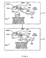
- Figs. 1 to 8D twenty-one different embodiments of the automatically-activated bar code symbol reading system of the present invention are shown. These twenty-one different embodiments can be classified into three different types of generalized system designs, each based on the general manner in which its underlying laser scanning mechanism is automatically-activated and controlled during the bar code symbol reading process of the present invention. These three different system designs are illustrated in Figs. 1A, 1B and 1C. In each of these generalized system designs, activation of the bar code symbol detection and bar code symbol reading operations is carried out in a fully automatic manner, without the use of a manually-activated trigger or like mechanism, as disclosed, for example, in US Patent Nos.
- the first generalized system design of the present invention is shown in Fig. 1A.
- Eight illustrative embodiments of this first generalized system design are represented by the first (2A), fourth (3A), seventh (4A), tenth (5A), thirteenth (6A), sixteenth (7A), nineteenth (8A) and twenty-second (8E1) embodiments shown in Figs. 2A to 2H, 3A to 3C, 4A to 4D, 5A, 6A, 7A, 8A, and 8E1, respectively.
- the hand-supportable, body-wearable or desktop-supportable bar code symbol reading device includes an automatically-activated bar code symbol scanning engine, embedded within the housing of the device. While hand-held, finger-supported, desktop-supported and body-wearable housings will be disclosed hereinafter for the bar code symbol reading device of the present invention, the term "hand-supportable housing" as used hereinafter and in the Claims to Invention shall be deemed to include all such housing designs, as well as an infinite array of variations on the form factors thereof. In general, any of the automatically-activated laser scanning bar code symbol reading engines shown in Figs.
- 9A to 9D, 10A to 10D, 11A, 13A and 14A can be embodied within the scanner housing of the bar code symbol reading device.
- particular laser scanning engine designs have been incorporated into the scanner housing of the bar code symbol reading device for illustrative purposes. It is understood, however, that other laser scanning engine designs can be integrated into the scanner housings of such bar code symbol reading devices.
- the automatically-activated bar code symbol scanning device of the first general system design 1 comprises a number of subsystems, namely: an IR-based object detection subsystem 2 as taught in prior US Patent Nos. 5,260,553 and 5,808,285, a laser-based bar code symbol detection subsystem 3; a laser-based bar code symbol reading subsystem 4; a data transmission subsystem 5; a state indication subsystem 6; a data transmission activation switch or control device 7A integrated with the scanner housing in part or whole; a mode-selection sensor 7B integrated with the scanner housing in part or whole; and a system control subsystem 8 operably connected to the other subsystems described above.
- system 1 has a number of preprogrammed operational states, namely: an Object Detection State; a Bar Code Symbol Detection State; a Bar Code Symbol Reading State; and a Data Transmission State.
- the IR-based object detection subsystem 2 performs the following primary functions during the object detection state: (i) automatically and synchronously transmitting and receiving pulse infrared (IR) signals within an IR-based object detection field 9 defined relative to the hand-supportable scanner housing (not shown) (ii) automatically detecting an object in at least a portion of the IR-based object detection field 9 by analysis of the received IR pulse signals; and (iii) in response thereto, automatically generating a first control activation signal A 1 indicative of such automatic detection of the object within the object detection field.
- the first control activation signal A 1 1 is provided to the system control subsystem 8 for detection, analysis and programmed response.
- object detection, bar code detection and bar code reading fields 9, 10 and 11, respectively have been schematically represented only in terms of their general geometrical boundaries. For purposes of clarity, the geometrical characteristics of these fields have not been shown. Notably, however, such characteristics can be ascertained from the various references relating thereto which are identified and incorporated herein by reference.
- the second control activation signal A 2 is provided to the system control subsystem 8 for detection, analysis and programmed response.
- the mode-select sensor 7B effectively overrides the data transmission switch 7A.
- the data transmission switch 7A effectively overrides the mode-select sensor 7B.
- the state indication subsystem 6 performs the following functions: automatically monitors the state of operation of the system at each instant of time; and automatically produces visual indication (e.g. color-coded light) signals from the scanner housing designed to inform the user of the current state of operation of the system (e.g. blue to indicate the object detection state, red to indicate the bar code detection state, yellow to indicate the bar code reading state, and green to indicate the symbol character data transmission state).
- visual indication e.g. color-coded light
- state indication signals provide the user with visual feedback on the states of operation of the system, thereby improving the intuitiveness and facility of operation of the system in diverse application environments.
- the system control subsystem 8 performs the following primary functions: (i) automatically receiving control activation signals A 1 , A 2 , A 3 and A 4 ; (ii) automatically generating enable signals E 1 , E 2 , E 3 , E 4 , E 5 , E 6 , and E 7 ; and (iii) automatically controlling the operation of the other subsystems in accordance with a system control program carried out by the system control subsystem 8 during the various modes of system operation.
- the geometrical and optical characteristics of laser scanning patterns generated by the laser-based bar code symbol detection subsystem 3 and the laser-based bar code symbol reading subsystem 4 will depend on each particular embodiment of the bar code symbol reading system of the present invention.
- the laser scanning patterns generated within the bar code detection and reading fields will be substantially congruent, and if not substantially congruent, then arranged so that the bar code symbol reading field 11 spatially-overlaps the bar code symbol detection field 10 to improve the scanning efficiency of the system.
- the IR-based object detection field 9 will be arranged relative to the bar code detection field 10 so that it spatially-encompasses the same along the operative scanning range of the system defined by the geometrical characteristics of the bar code reading field 11 thereof.
- detected energy reflected from an object during object detection can be optical radiation or acoustical energy, either sensible or non-sensible by the user, and may be either generated from the automatic bar code reading device or an external ambient source.
- the provision of such energy is preferably achieved by transmitting a wide beam of pulsed infrared (IR) light away from transmission aperture of the scanner, as taught herein.
- the object detection field 9, from which such reflected energy is collected is designed to have a narrowly diverging pencil-like geometry of three-dimensional volumetric expanse, which is spatially coincident with at least a portion of the transmitted infrared light beam.
- This feature of the present invention ensures that an object residing within the object detection field 9 will be illuminated by the infrared light beam, and that infrared light reflected therefrom will be directed generally towards the transmission aperture of the housing where it can be automatically detected to indicate the presence of the object within the object detection field 9.
- the laser scanning pattern scans a bar code symbol on the detected object
- scan data signals are produced therefrom, collected, detected and processed to determine whether a bar code symbol has been scanned within the bar code symbol detection field 10. If the scanned bar code symbol is detected, then the system control subsystem 8 automatically generates enable signal E 3 and E 4 so as to activate the bar code symbol reading subsystem 4.
- the laser-based bar code reading subsystem 4 automatically generates a laser scanning pattern within the laser-based bar code reading field 11, scans the detected bar code symbol disposed therewithin, collects scan data therefrom, decodes the detected bar code symbol, generates symbol character data representative of the decoded bar code symbol, and buffers the symbol character data in memory.
- the system control subsystem 8 automatically activates the data transmission subsystem 5.
- the data transmission subsystem 5 automatically transmits the produced/buffered symbol character data to the host system (to which the bar code symbol reader is connected), a data storage buffer (e.g. disposed in a portable data collection device connected to the bar code symbol reader), or other data storage/processing device.
- the user is permitted to read bar code symbols in a highly intuitive manner, wherein object detection, bar code detection, and bar code symbol reading are carried out in an automatic manner while data transmission of decoded symbol character data to the host device is enabled by manual-activation of a switch, button or like device located on the exterior of the hand-supportable scanner housing.
- a visual state indicator is provided on the scanner housing for visually indicating that a bar code symbol has been successfully read in a fully-automatic manner, and that the system is ready for data transmission enablement to the host system or like device.
- the user When the visual indicator indicates that a bar code symbol is being read and decoded symbol character data is being generated, the user need only depress the data transmission activation switch on the scanner housing to send subsequently produced symbol character data to the host system or like device. Failure to depress the data transmission switch 7A within the preallotted time frame during automatic bar code symbol reading results in there not being any symbol character data transmission to the host system.
- the IR-based object detection subsystem 2 is realized from various electro-optical and electro-mechanical components assembled together as shown in Figs. 15A1 through 15A4, so as to enable automatic detection of objects within the IR-based object detection field 9 of the system.
- the laser-based bar code symbol detection subsystem 3 is realized from various electro-optical and electro-mechanical components assembled together as shown in Fig. 15A1 to 15A4, so as to enable automatic detection of bar code symbols on detected objects within the laser-based bar code detection field of the system.
- the laser-based bar code symbol reading subsystem 4 is realized from various electro-optical and electro-mechanical components assembled together so as to enable automatic reading of detected bar code symbols within the laser-based bar code reading field 11 of the system.
- this system embodiment requires a complex control subsystem architecture, but offers a significant improvement in power conservation which can be very important in portable and mobile data acquisition applications.
- the second generalized system design of the present invention is shown in Fig. 1B.
- the automatically-activated bar code symbol scanning engine of the second general system design 15 comprises a number of subsystems, namely: a laser-based object detection subsystem 16 as taught in prior US Patent Nos. 4,933,538 to Heiman, et al., a laser-based bar code symbol detection subsystem 17; a laser-based bar code symbol reading subsystem 18; a data transmission subsystem 19; a state indication subsystem 20; and a data transmission activation switch or control device 21A integrated with the scanner housing in part or whole; a mode-selection sensor 21B integrated with the scanner housing it part or whole; and a system control subsystem 22 operably connected to the other subsystems described above.
- system 15 has a number of preprogrammed states of operation, namely: an Object Detection State; a Bar code Symbol Detection State; a Bar code Symbol Reading State; and a Data Transmission State.
- the laser-based object detection subsystem 16 performs the following primary functions: (i) automatically generates and scans a low-power pulsed (invisible) laser scanning beam across an object within a laser-based object detection field 23 defined relative to the hand-supportable scanner housing (not shown); (ii) automatically detects an object in at least a portion of the laser-based object detection field by analysis of collected scan data; and (iii) in response thereto, automatically generating a first control activation signal A 1 indicative of such automatic detection of the object within the object detection field 23.
- the first control activation signal A 1 is provided to the system control subsystem 22 for detection, analysis and programmed response.
- the laser-based bar code symbol detection subsystem 17 performs the following primary functions during the Bar Code Symbol Detection State: (i) automatically generating a laser scanning pattern of predetermined characteristics within the laser-based bar code (symbol) detection field 24, defined relative to the scanner housing, to enable scanning of a bar code symbol on the detected object; (ii) automatically processing scan data collected from the bar code symbol detection field 24 and detecting the presence of the bar code symbol thereon; and (iii) automatically generating a control activation signal A 2 indicative thereof in response to the automatic detection of the bar code symbol. As shown in Fig. 1B, the second control activation signal A 2 is provided to the system control subsystem 22 for detection, analysis and programmed response.
- object detection, bar code detection and bar code reading fields 23, 24 and 25, respectively have been schematically represented only in terms of their general geometrical boundaries. For purposes of clarity, the geometrical characteristics of these fields have not been shown. Notably, however, such characteristics can be ascertained from the various references relating thereto which are identified and incorporated herein by reference.
- the mode-select sensor 21B effectively overrides the data transmission switch 21A.
- the data transmission switch 21 A effectively overrides the mode-select sensor 21B.
- the state indication subsystem 20 performs the following functions: automatically monitor the state of operation of the system at each instant of time; and automatically produce visual indication (e.g. color-coded light) signals from the scanner housing designed to inform the user of the current state of operation of the system (e.g. blue to indicate the object detection state, red to indicate the bar code detection state, yellow to indicate the bar code reading state, and green to indicate the symbol character data transmission state).
- visual indication e.g. color-coded light
- state indication signals provide the user with visual feedback on the states of operation of the system, thereby improving the intuitiveness and facility of operation of the system in diverse application environments.
- the system control subsystem 22 performs the following primary functions: (i) automatically receiving control activation signals A 1 , A 2 , A 3 and A 4 ; (ii) automatically generating enable signals E 1 , E 2 , ,E 3 , E 4 , E 5 , E 6 , and E 7 ; and (iii) automatically controlling the operation of the other subsystems in accordance with a system control program carried out by the system control subsystem 22 during the various modes of system operation.
- the geometrical and optical characteristics of laser scanning patterns generated by the laser-based bar code symbol detection subsystem 17 and the laser-based bar code symbol reading subsystem 18 will depend on each particular embodiment of the bar code symbol reading system of the present invention.
- the laser scanning patterns generated within the bar code detection and reading fields will be substantially congruent, and if not substantially congruent, then arranged so that the bar code symbol reading field spatially-overlaps the bar code symbol detection field to improve the scanning efficiency of the system.
- the laser-based object detection field will be arranged relative to the bar code detection field so that it spatially-encompasses the same along the operative scanning range of the system defined by the geometrical characteristics of the bar code reading field thereof.
- the laser scanning pattern scans a bar code symbol on the detected object
- scan data signals are produced therefrom, collected, detected and processed to determine whether a bar code symbol has been detected within the bar code symbol detection field 24. If the scanned bar code symbol is detected, then the system control subsystem 22 automatically generates enable signal E 3 and E 4 so as to activate the bar code symbol reading subsystem 18.
- the laser-based bar code reading subsystem 18 automatically generates a visible laser scanning pattern within the laser-based bar code reading field 25, scans the detected bar code symbol disposed therewithin, collects scan data therefrom, decodes the detected bar code symbol, generates symbol character data representative of the decoded bar code symbol, and buffers the symbol character data in memory.
- the system control subsystem 22 automatically activates the data transmission subsystem 19.
- the data transmission subsystem 19 automatically transmits the produced/buffered symbol character data to the host system (to which the bar code symbol reader is connected), a data storage buffer (e.g. disposed in a portable data collection device connected to the bar codc symbol reader), or other data storage/processing device.
- the user is permitted to read bar code symbols in a highly intuitive manner, wherein object detection, bar code detection, and bar code symbol reading are carried out in an automatic manner while data transmission of decoded symbol character data to the host device is enabled by manual-activation of a switch, button or like device located on the exterior of the hand-supportable scanner housing.
- a visual indicator is provided on the scanner housing for visually indicating that a bar code symbol has been successfully read in a fully-automatic manner, and that the system is ready for data transmission to the host system or like device.
- the visual indicator indicates that a bar code symbol is being read and decoded symbol character data is being generated, the user need only depress the data transmission control activation switch 21A on the scanner housing to send subsequently produced symbol character data to the host system or like device.
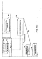
- Fig. 1C The third generalized system design of the present invention is shown in Fig. 1C.
- the automatically-activated bar code symbol scanning engine of the third general system design 30 comprises a number of subsystems, namely: a laser-based bar code symbol detection subsystem 31; a laser-based bar code symbol reading subsystem 32; a data transmission subsystem 33; a state indication subsystem 34; a data transmission activation switch or control device 35A integrated with the scanner housing (not shown) in part or whole; a mode-selection sensor 35B integrated with the scanner housing it part or whole; and a system control subsystem 36 operably connected to the other subsystems described above.
- the system 30 has a number of preprogrammed states of operation, namely: a Bar Code Symbol Detection State; a Bar code Symbol Reading State; and a Data Transmission State.
- the mode-select sensor 35B In the automatic hands-free mode of operation, the mode-select sensor 35B effectively overrides the data transmission switch 35A. In the automatic hands-on mode of operation, the data transmission switch 35A effectively overrides the mode-select sensor 35B.
- the state indication subsystem 34 performs the following functions: automatically monitors the state of operation of the system at each instant of time; and automatically produces visual indication (e.g. color-coded light) signals from the scanner housing designed to inform the user of the current state of operation of the system (e.g, red to indicate the bar code detection state, yellow to indicate the bar code reading state, and green to indicate the symbol character data transmission state).
- visual indication e.g. color-coded light
- state indication signals provide the user with visual feedback on the states of operation of the system, thereby improving the intuitiveness and facility of operation of the system in diverse application environments.
- the system control subsystem 36 performs the following primary functions: (i) automatically receiving control activation signals A 1 A 2 , A 3 and A 4 ; (ii) automatically generating enable signals E 2 , E 3 , E 4 , E 5 , E 6 , and E 7 ; and (iii) automatically controlling the operation of the other subsystems in accordance with a system control program carried out by the system control subsystem 36 during the various modes of system operation.
- the geometrical and optical characteristics of laser scanning patterns generated by the laser-based bar code symbol detection subsystem 31 and the laser-based bar code symbol reading subsystem 32 will depend on each particular embodiment of the bar code symbol reading system of the present invention.
- the laser scanning patterns generated within the bar code detection and reading fields will be substantially congruent, and if not substantially congruent, then arranged so that the bar code symbol reading field spatially-overlaps the bar code symbol detection field to improve the scanning efficiency of the system.
- This causes the laser-based bar code detection subsystem 31 to generate a pulsed laser scanning pattern of predetermined characteristics within the laser-based bar code detection field 37.
- the pulse-on duration of the laser signal is about 50%, while the pulse-off duration is also about 50%.
- the laser-based bar code reading subsystem 32 automatically generates a visible laser scanning pattern within the laser-based bar code reading field 38, scans the detected bar code symbol disposed therewithin, collects scan data therefrom, decodes the detected bar code symbol, generates symbol character data representative of the decoded bar code symbol, and buffers the symbol character data in memory. If the detected bar code symbol is read within a predetermined period of time, and the manually-actuated data transmission switch 35A is depressed within a predetermined time frame established by the system control subsystem 36, then the system control subsystem 36 automatically activates the data transmission subsystem 33.
- the data transmission subsystem automatically transmits the produced/buffered symbol character data to the host system (to which the bar code symbol reader is connected), a data storage buffer (e.g. disposed in a portable data collection device connected to the bar code symbol reader), or other data storage/processing device.
- the host system to which the bar code symbol reader is connected
- a data storage buffer e.g. disposed in a portable data collection device connected to the bar code symbol reader
- other data storage/processing device e.g. disposed in a portable data collection device connected to the bar code symbol reader
- the user is permitted to read bar code symbols in a highly intuitive manner, wherein bar code detection and bar code symbol reading are carried out in an automatic manner while data transmission of decoded symbol character data to the host device is enabled by manual-activation of a switch, button or like device located on the exterior of the hand-supportable scanner housing.
- a visual indicator is provided on the scanner housing for visually indicating that a bar code symbol has been successfully read in a fully-automatic manner, and that the system is ready for data transmission enablement to the host system or like device.
- the visual indicator indicates that a bar code symbol is being read and decoded symbol character data is being generated, the user need only depress the data transmission enabling switch on the scanner housing to send the subsequently produced data to the host system or like device.
- the structure and functionalities of the third general system design of Fig. 1C described above does not provide for automatic object detection within the system, but simply provides a continuously-operating bar code symbol presence detection subsystem for automatic detection of bar codes within the scanning field of the system.
- the laser-based bar code symbol detection subsystem 31 is realized from various electro-optical and electro-mechanical components assembled together, so as to enable automatic detection of bar code symbols on detected objects within the laser-based bar code detection field of the system.
- the laser-based bar code symbol reading subsystem is realized from various electro-optical and electro-mechanical components assembled together, so as to enable automatic reading of detected bar code symbols within the laser-based bar code reading field of the system.
- this system design requires an even simpler control subsystem architecture than system designs employing automatic object detection.
- this system design requires that a low-power (non-visible) laser beam be continuously or periodically generated within the bar code symbol detection field during system operation, thus consuming electrical power which can be significant in portable and mobile scanning applications where battery power is used.
- each of the three generalized bar code symbol reading systems described hereinabove can be connected to its base unit, host computer, data processor, data storage device, or like device by way of wires wrapped in a flexible cord-like structure
- the wireless data communication link can be realized in a variety of different ways, namely: using the two-way RF communication link of the type disclosed in US Patent Nos. 4,460,120; 5,321,246 and 5,142,550 or using the one-way data transmission link as disclosed in US Patent No. 5,808,285 to Rockstein, et al; etc.
- the bar code symbol reading system of the first illustrative embodiment 40 comprises an automatically-activated portable bar code symbol reading device 41 operably associated with a base unit 42 having a scanner support stand 43.
- Bar code symbol reading device 41 is operably connected with its the base unit 42 by way of a one-way or two-way electromagnetic link established between bar code symbol reading device 41 and its mated base unit 42.
- symbol character data representsative of the read bar code symbol
- Operable interconnection between the base unit 42 and a host system (e.g. electronic cash register system, data collection device, etc.) 45 is achieved by a flexible multiwire communications cable 46 extending from the base unit and plugged directly into the said data-input communications port of the host computer system 45.
- electrical power from a low voltage direct current (DC) power supply (not shown) is provided to the base unit by way of a flexible power cable 47.
- DC power supply can be realized in host computer system 45 or as a separate DC power supply adapter pluggable into a conventional 3-prong electrical socket.
- a rechargeable battery power supply unit 55 is contained within bar code symbol reading device 41 in order to energize the electrical and electro-optical components within the device.
- portable bar code reading device 41 includes an ultra-light weight hand-supportable housing 49 having a contoured head portion 49A and a handle portion 49B.
- head portion 49A encloses electro-optical components which are used to generate and project a visible laser beam through light transmissive window 50 in housing head portion 49A, and to repeatedly scan the projected laser beam across its bar code detecting scanning field 10 and bar code reading field 11, both defined external to the hand-supportable housing.
- the scanner support stand portion 43 includes a support frame which comprises a base portion 51A, a head portion support structure 51B, handle portion support structure 51C and a finger accommodating recess 51 D.
- base portion 51A has a longitudinal extent and is adapted for selective positioning with respect to a support surface, e.g. countertop surface, counter wall surface, etc.
- An aperture 51A 1 is formed in the base portion 51A to allow an piezo-electric transducer 559 to generate acoustical acknowledgement signals therethrough upon successful data transmission to the base unit.
- Head portion support structure 51B is connected to base portion 51A, for receiving and supporting the head portion of bar code symbol reading device 41.
- handle portion support structure 51C is connected to base portion 51A, for receiving and supporting the handle, portion of the code symbol reading device.
- finger-accommodating recess 51 D is disposed between head and handle portion support structures 51B and 51C and base portion 51A of the support frame.
- finger-accommodating recess 51D is laterally accessible so that when the head and handle portions 49A and 49B are received within and supported by head portion support structure 51B and handle portion support structure 51C, respectively, the fingers of a user's hand can be easily inserted through finger accommodating recess 51 D and completely encircle the handle portion of the hand-supportable device.
- bar code symbol reading device 41 includes a mode-selector sensor 800 (e.g. electronic of electrical/mechanical sensor) located on the end portion of the hand-supportable housing.
- head portion 49A continuously extends into contoured handle portion 49B at an obtuse angle which, in the illustrative embodiment, is about 146 degrees. It is understood, however, that in other embodiments the obtuse angle may be in the range of about 135 to about 180 degrees.
- this ergonomic housing design is sculptured (i.e. form-fitted) to the human hand, automatic hands-on scanning is rendered as easy and effortless as waving one s hand.
- the head portion of housing 49A has a light transmission aperture 50 formed in upper portion of the front panel 52A, to permit visible laser light to exit and enter the housing, as will be described in greater detail hereinafter.
- the lower portion of front panel 52B is optically opaque, as are all other surfaces of the hand supportable housing.
- an automatically-activated laser- scanning bar code symbol reading engine 53 is securely mounted within the head portion of hand-supportable housing 49A, while a printed circuit (PC) board 54 and a rechargeable battery supply unit 55 are mounted within the handle portion of the hand-supportable housing portion 49B.
- a data packet transmission circuit 56 is realized on PC board 54 in housing 49B and is operably connected to bar code symbol reading engine 53 contained therein by way of a first flexible wire harness 57. Electrical power is supplied from rechargeable battery 55 to the data packet transmission circuit 56 and the bar code symbol reading engine 53 by way of a second flexible wire harness 58.
- a transmitting antenna 59 is operably connected to the data packet transmission circuit 56 on PC board 54 and is mounted within hand-supportable housing portion 49B for transmission of a data packet modulated RF carrier signal to a base unit associated with the automatic bar code symbol reading device.
- the structure and the functionalities of the different types of automatic bar code symbol reading engines that can be incorporated into the device of Fig. 2A will be described in greater detail hereinafter.
- the first generalized system design will now be described in greater detail.
- the structure and functions of the first generalized system design are provided within each of illustrative embodiments of the present invention described above relating to automatically-activated bar code symbol reading systems comprising an IR-based object detection subsystem, a laser-based bar code presence detection subsystem, a laser-based bar code symbol reading subsystem and data transmission activation subsystem, as illustrated in Fig. 1A.
- second control circuit C 2 is capable of "overriding” (i.e. inhibit and/or enable) first control circuit C 1
- third control circuit C 3 is capable of overriding first and second control circuits C 1 and C 2 , respectively.
- control override functions are carried out by the generation of control override signals (i.e. C 2 /C 1 , C 3 /C 2 and C 3 /C 1 ) transmitted between respective control structures during system operation.
- control override signals i.e. C 2 /C 1 , C 3 /C 2 and C 3 /C 1
- the automatically activated bar code symbol reading device hereof is capable of versatile performance and ultra-low power operation. The structure, function and advantages of this control subsystem architecture will become apparent hereinafter.
- laser scanning circuit 308 comprises a light source 377 which, in general, may be any source of intense light suitably selected for maximizing the reflectivity from the object bearing a bar code symbol.
- light source 377 comprises a solid-state visible laser diode (VLD) which is driven by a conventional driver circuit 378.
- VLD visible laser diode
- the wavelength of visible laser light produced from the laser diode is preferably about 670 nanometers.
- any number of laser beam scanning mechanisms can be used.
- a scanner motor 380 is used to represent this structure in the system.
- this scanning motor 380 need not be electro-mechanical in nature, but may be based on electro-optical beam scanning/steering principles employing, for example, cholesteric liquid crystal (CLC) Laser Beam Steering Arrays disclosed in U.S. Patent No. 5,459,591.
- CLC cholesteric liquid crystal
- the term "scanning motor as used herein is understood as any means for moving, steering, swinging or directing the path of a light beam through space during system operation for the purpose of obtaining information relating to an object and/or a bar code symbol.
- laser diode 377 and scanning motor 380 are enabled by enable signal E 1 provided as input to driver circuits 378 and 381.
- a laser beam is generated and projected through the light transmissive window, and repeatedly scanned across the bar code symbol detection field, and an optical scan data signal is thereby produced off the object (and bar code) residing within the bar code symbol detection field 10.
- Photoreceiving circuit 309 detects at least a portion of the reflected laser light of variable intensity and produces an analog scan data signal D 1 indicative of the detected light intensity.
- photoreceiving circuit 309 generally comprises a number of components, namely: laser light collection optics (e.g. planar or parabolic mirror 379, focusing lens 384) for focusing reflected laser light for subsequent detection; a photoreceiver 385 (e.g. a silicon photosensor) for detecting laser light focused by the light collection optics; and a frequency-selective filter 386A, mounted in front of photoreceiver 385, for transmitting thereto only optical radiation having wavelengths up to a small band above 670 nanometers.
- laser light collection optics e.g. planar or parabolic mirror 379, focusing lens 384
- a photoreceiver 385 e.g. a silicon photosensor
- a frequency-selective filter 386A mounted in front of photoreceiver 385, for transmitting thereto only optical radiation having wavelengths up to a small band above 670 nanometers.
- the light transmissive window disposed over the light transmission aperture is realized as a plastic filter lens 386B is installed over the light transmission aperture of the housing.
- This plastic filter lens has optical characteristics which transmit only optical radiation from slightly below 670 nanometers.
- this optical arrangement provides improved signal-to-noise ratio for detected scan data signals D 1 , as described in greater detail in U.S. Patent No. 5,789,731.
- the photoreceiver In response to reflected laser light focused onto photoreceiver 385, the photoreceiver produces an analog electrical signal which is proportional to the intensity of the detected laser light. This analog signal is subsequently amplified by preamplifier 387 to produce analog scan data signal D 1 .
- laser scanning circuit 308 and photoreceiving circuit 309 cooperate to generate analog scan data signals D 1 from the scanning field (i.e. bar code detection and reading fields), over time intervals specified by first and second control circuits C 1 and C 2 during normal modes of operation, and by third control module C 3 during "control override" modes of operation.
- the third control module C 3 Upon entering the bar code symbol reading state, the third control module C 3 provides override control signal C 3 /C 1-2 to the first control circuit C 1 .
- the symbol decoding module 319 decode processes, scan line by scan line, the stream of digitized scan data contained in signal D 2 in an attempt to decode the detected bar code symbol within the second predetermined time period T 2 established and monitored by the third control module C 3 . If the symbol decoding module 319 successfully decodes the detected bar code symbol within time period T 2 , then symbol character data D 3 (representative of the decoded bar code symbol and typically in ASCII code format) is produced. Thereupon symbol decoding module 319 produces and provides the third control activation signal A 3 to the third control module C 3 .
- the third control module C 3 automatically induces a state transition from the bar code symbol reading state to the data (packet) transmission state.
- three distinct events are programmed to occur. Firstly, the third control module C 3 automatically produces and provides enable signal E 5 to data packet synthesis module 320. Secondly, symbol decoding module 319 stores symbol character data D 3 in a memory buffer associated with data packet synthesis module 320. Thirdly, the third control module C 3 produces and provides enable signal E 7 to the data packet transmission circuit 321.
- the third control module C 3 can produce and provide enable signal E 6 to the data storage module, and thereafter produce and provide enable signal E 7 to the data transmission circuit 321.
- These enabling events activate the data (packet) transmission subsystem of the system shown in Fig. 15.
- the subsequently produced symbol character data string is transmitted to the base unit 440, and therefrom to the host computer 441.
- symbol decoding module 319 data packet synthesis module 320, and timers T 2 , T 3 , T 4 and T 5 are each realized using programmed microprocessor and accessible memory 334.
- the third control module C 3 and the control functions which it performs at Blocks I to GG in Figs. 20A1 through 20E, for example, are realized as a programming implementation using techniques well known in the art.
- the function of data packet synthesis module 320 is to use the produced symbol character data to synthesize a group of data packets for subsequent transmission to its mated base unit 440 by way of data packet transmission circuit 321.
- the construction of the data packet transmission circuit 321 will vary from embodiment to embodiment, depending on the type of data communication protocol being used in the particular embodiment of the bar code symbol reading system.
- the data packet transmission circuit 321 comprises a carrier signal generation circuit 430, a carrier signal frequency modulation circuit 431, a power amplifier 432, a matching filter 433, and a quarterwave (1/4) transmitting antenna element 434.
- the function of the carrier signal generation circuit 430 is to generate a carrier signal having a frequency in the RF region of the electromagnetic spectrum.
- the carrier frequency is about 912 Mhz, although it is understood that this frequency may vary from one embodiment of the present invention, to another embodiment thereof.
- frequency modulation circuitry 431 modulates the instantaneous frequency of the carrier signal using the digital data sequence (i.e.
- the function of the power amplifier 432 is to amplify the power of the transmitted modulated carrier signal so that it may be received by a base unit 440 located within a predetermined data transmission range (e.g. from about 0 to about 30 feet), illustrated in Figs. 2D and 3D, in particular.
- a base unit 440 located within a predetermined data transmission range (e.g. from about 0 to about 30 feet), illustrated in Figs. 2D and 3D, in particular.
- This initialization step involves: activating (i.e. enabling) system override detection circuit 301, first control circuit C 1 (304), oscillator circuit 301, the system override signal producing means 333, and IR-based object sensing circuit 306; and deactivating (i.e. disabling) laser scanning circuit 308, photoreceiving circuit 309, and all subcircuits aboard ASIC chip 333 shown in Figs. 15A1-15A4 that are not associated with the system override detection circuit 301, i.e.
- Block H the system control process hereof proceeds to Block I, at which the data element stored in the Decoded Symbol Data Buffer (e.g. in the second control circuit C 2 and/or third control module C 3 ) is set to zero, and then the system control process returns back to Block A via Blocks HH and II.
- a second predetermined time period e.g. 0 ⁇ T 2 ⁇ 1 second
- resets and restarts timer T 3 permitting it to run for a third predetermined time period (e.g. 0 ⁇ T 3 ⁇ 5.0 seconds).
- the control system may progress through the control loop defined by Blocks L-M-N-L several times before a bar code symbol in the laser-based bar code symbol reading field 11 is read within the time period allotted by timer T 3 .
- the allotted time period is 5.0 seconds.
- the time period may be greater or lesser than this exemplary time period without departing from the principles of the present invention.
- a short predetermined time period e.g. 60 milliseconds
- the control module C 3 determines whether the data within the Decoded Symbol Data Buffer has been set to zero value. If this data has not been set to zero value, then the system control process advances to Block T, at which the control module C 3 determines whether the bar code symbol character data produced by the symbol decoding module is different than the symbol character data stored in the Decoded Symbol Data Buffer. If these data elements are not the same, then the system control process advances to Block U, where the control module determines whether Timer T3 has elapsed. If Timer T3 has elapsed, then the system control process returns to Block H, as shown in Fig. 20A2. If, however, the Timer T3 has not elapsed at Block U, then the system control process returns to Block M, as shown in Fig. 20B.
- Block S in Fig. 20C the control module C 3 has determined that the data set in the Decoded Symbol Data Buffer is not zero value, then the system control process advances to Block V, at which the control module C 3 stores the symbol character data (produced by the symbol decoding module 319) into the Decoded Symbol Data Module. Thereafter, the system control process proceeds to Block W, at which the third control module C 3 continues activation of laser scanning circuit 308, photoreceiving circuit 309, and A/D conversion circuit 310, while deactivating symbol decoding module 319 and commencing activation of data packet synthesis module 320. While the laser beam is being continuously scanned during the data transmission state of operation, the operations at Blocks X to DD described below, are carried out in a high speed manner under the orchestration of control module C 3 .
- the data packet synthesis module 320 first sets the Packet Number to "1", and increments the Packet Group Number from the previous number.
- the data packet synthesis module keeps track of (i.e. manages) the "Packet Number" using a first module-N counter realized by programmable microprocessor 334, while it manages the "Packet Group Number" using a second modulo-M counter also realized by programmed microprocessor 334.
- the data packet synthesis module 320 synthesizes or constructs a data packet having a packet format as shown in Fig. 150, i.e. consisting of symbol character data, a Transmitter Identification Number, a Packet Number, a Packet Group Number, check character, and Packet Start and End (i.e. framing) Characters.
- the third control module C 3 activates at Block Z the data packet transmission circuit 321.
- the data packet synthesis module 320 outputs the buffered digital data sequence (of the first synthesized data packet of the group) to the data packet transmission circuit, which uses the digital data sequence to modulate the frequency of the carrier signal as it is being transmitted from the bar code symbol reading device, to its mated base unit 440, as described hereinabove, and then automatically deactivates itself to conserve power.
- the third control module C 3 determines whether the Packet Number counted by the first module counter is less than "3". If the Packet Number of the recently transmitted data packet is less than "3", indicating that at most only two data packets in a specific group have been transmitted, then at Block CC the data packet synthesis module 320 increments the Packet Number by +1.
- the third control module then waits for a time delay T 5 maintained by Timer T 5 to lapse prior to the control system returning to Block Y, as shown in Fig. 20D. Notably, the occurrence of time delay T 5 causes a delay in transmission of the next data packet in the data packet group. As illustrated in Fig.
- time delay T 5 is a function of the (last two digits of the) Transmitter Number of the current data packet group, and thus is a function of the bar code symbol reading device transmitting symbol character data to its mated base unit. For the case of three data packet groups, time delay T 5 will occur between the transmission of the first and second data packets in a packet group and between the transmission of the second and third data packets in the same packet group.
- the data packet synthesis module 320 synthesizes or constructs the second data packet in the same data packet group.
- the third control module C 3 reactivates, at Block Z, the data packet transmission circuit 321.
- the data packet synthesis module outputs the buffered digital data sequence (of the second synthesized data packet) to the data packet transmission circuit (34), which uses the digital data sequence to modulate the frequency of the carrier signal as it is being transmitted from the bar code symbol reading device, to its mated base unit 440, and thereafter automatically deactivates itself.
- third control module C 3 determines that the Packet Number is equal to "3"
- the control system advances to Block EE in Fig. 20E.
- control activation signal A 1 1 is received, then at Block GG the third control module C 3 reactivates the bar code symbol detection circuit 311 using override signal C 3 /C 2 , and resets and restarts timer T 3 to start running over its predetermined time period, i.e. 0 ⁇ T 3 ⁇ 5 seconds, and resets and restart timer T 4 for a predetermined time period 0 ⁇ T 4 ⁇ 3 seconds. Thereafter, the system control process returns to Block F in Fig. 20A2 in order to attempt to read another bar code symbol.
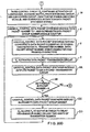
- the automatic hand-supportable bar code reading device of the present invention has four basic states of operation, namely: object detection, bar code symbol presence detection, bar code symbol reading, and symbol character data transmission/storage. The nature of each of these states has been described above in great detail.
- Transitions between the various states are indicated by directional arrows. Besides each set of directional arrows are transition conditions expressed in terms of control activation signals (e.g. A 1 , A 2 , A 3 and A 4 ) and where appropriate, state time intervals (e.g. T 1 , T 2 , T 3 , T 4 , and T 5 ).
- control activation signals e.g. A 1 , A 2 , A 3 and A 4
- state time intervals e.g. T 1 , T 2 , T 3 , T 4 , and T 5 .
- the state diagram of Fig. 21 expresses most simply the four basic operations occurring during the control flow within the system control program of Figs. 20A1 to 20E.
- the control activation signals A 1 , A 2 , A 3 and A 4 shown in Fig. 21 indicate which events within the object detection field 9, the bar code detection field 10 and/or the bar code reading fields 11 can operate to affect a state transition within the allotted time frame(s
- Modifications may be made to certain components in the system in order to enter "Time-Extended States of Operation" which provides the user with an extended time period (e.g. 20 seconds) within which to (i) read (detect and decode) a bar code symbol on the detected object and (ii) manually-enable the transmission of its symbol character data to the associated host computer system.
- the system enters this Time-Extended States of Operation whenever a detected object remains within the object detection field of the system whenever a timer, set to run, "times out” within the system control process. Examples of when a timer may "time out” in the system control process include, for example: when the system fails to read (i.e.
- the laser beam is pulsed (i.e. flickered) at the flicker-frequency rate during both bar code detection and reading modes of operation.
- Such modifications offer many important advantages to the user while reading bar coded objects of various sorts. For example, when a user brings a bar coded object within the IR-based object detection field of the system and automatically detects the object, but the system does not read (i.e. detect and decode) the bar code symbol thereon and/or the user fails to transmit produced symbol character data to the host system by manual-activation of the data transmission switch 303, the system automatically enters the Time-Extended States of Operation and is provided an additional time period (e.g.
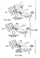
- the first step of the method involves moving an automatically-activated bar code symbol reading device of the present invention adjacent a bar code symbol menu 660, as shown in Fig. 42A.
- the visible laser scanning beam is shown scanned across two bar code symbols (652A and 652B) for illustrative purposes.
- the bar code symbol reading system automatically generates a new bar code symbol character data string each time a bar code symbol is read during the bar code symbol reading cycle.
- both of the scanned bar code symbols 652A and 652B are assumed to be read in an alternating manner, and thus (bar code) symbol character data strings (i.e. elements) representative thereof are automatically generated in a cyclical manner, as shown in Fig. 42A.
- symbol character data strings are repeatedly generated and the "bar code symbol read state" indicator repeatedly driven in correspondence with the generated symbol character data, but none of these symbol character data elements are transmitted to the host system 45 during this phase of the bar code symbol reading cycle.
- Fig. 42B the user is shown moving the bar code symbol reader closer to a particular bar code symbol sought to be read.
- symbol character data strings associated with the particular bar code symbol
- the "bar code symbol read state" indicator repeatedly driven in correspondence with the generated symbol character data, but none of these symbol character data elements are transmitted to the host system 45 during this phase of the bar code symbol reading cycle.
- Fig. 42C the user is shown depressing the data transmission switch 44 on the automatically-activated bar code symbol reading device 41 momentarily after the bar code symbol read state indicator has been observed to be driven.
- a subsequently produced symbol character data string (associated with the particular bar code symbol) is automatically selected within the bar code symbol reading device and transmitted to the host system to which it is connected.
- the "data transmission state" indicator on the device is momentarily driven for the user to see in the form of visual feedback.
- the user need only depress the data transmission switch 44 once again while the particular bar code symbol remains aligned with the visible scanning beam.
- Such retransmission of the symbol character data string is carried out upon each depression of the data transmission switch 44. Notably, during each retransmission of symbol character data, there is no need to redetect the object underlying the bar code symbol, or momentarily moving off the read bar code symbol before rereading it and retransmitting its symbol character data to the host system.
Claims (9)
- Verfahren zum Lesen von Barcodesymbolen auf einem Objekt unter Gebrauch eines mit der Hand haltbaren Geräts (1, 41, 1002), das die folgenden Schritte umfasst:a) wiederholtes Lesen eines oder mehrerer Barcodesymbole auf einem Objekt innerhalb eines vorbestimmten Zeitraums und als Reaktion auf jedes erfolgreiche Lesen eines der Barcodesymbole innerhalb des vorbestimmten Zeitraums Erzeugen einer neuen Symbolzeichendatenkette, die für das gelesene Barcodesymbol repräsentativ ist, undb) manuelles Betätigen eines Datenübertragungsschalters (7A, 44, 1003), der in das mit der Hand haltbare Gerät integriert ist, zum Erzeugen eines Datenübertragungsaktivierungssteuersignals innerhalb des vorbestimmten Zeitraums,c) als Reaktion auf das Datenübertragungsaktivierungssignal Auswählen und Übertragen einer der erzeugten Symbolzeichendatenketten zu einem Hostsystem (45, 441, 1009), das operativ mit dem mit der Hand haltbaren Gerät verbunden ist.
- Verfahren nach Anspruch 1, das ferner das Erzeugen einer visuellen Anzeige bei jedem neuen erfolgreichen Lesen eines der Barcodesymbole umfasst.
- Verfahren nach Anspruch 1, das ferner die folgenden Schritte umfasst:Erzeugen des Datenübertragungssteueraktivierungssignals als Reaktion auf das Abstellen des mit der Hand haltbaren Geräts auf einem Scannerständer oder einer Tresenoberfläche.
- Verfahren nach Anspruch 1, wobei der Schritt (c) ferner das Übertragen über drahtlose elektromagnetische Übertragung der ausgewählten Symbolzeichendatenkette zu einer dezentralen Basisstation, die operativ mit dem Hostsystem verbunden ist, umfasst.
- Verfahren nach Anspruch 4, das ferner Folgendes umfasst:Anzeigen von Daten auf einem Anzeigefeld, das in das mit der Hand haltbare Gerät eingebaut ist, und manuelles Eingeben von Daten in das mit der Hand haltbare Gerät unter Einsatz einer Dateneingabevorrichtung, die in das mit der Hand haltbare Gerät eingebaut ist.
- System zum Lesen von Barcodesymbolen auf einem Objekt, unter Verwendung einer mit der Hand haltbaren Vorrichtung (1, 41, 1002), gekennzeichnet durch:ein Barcodesymbollesesystem (4, 18, 32, 53, 319, 334) zum wiederholten Lesen eines oder mehrerer Barcodesymbole auf einem Objekt innerhalb eines vorbestimmten Zeitraums und als Reaktion auf jedes erfolgreiche neue Lesen eines der Barcodesymbole innerhalb des vorbestimmten Zeitraums Erzeugen einer neuen Symbolzeichendatenkette, die für das gelesene Barcodesymbol repräsentativ ist, undein manuell aktivierbarer Datenübertragungsschalter (7A, 44, 1003), der in das mit der Hand haltbare Gerät eingebaut ist, um ein Datenübertragungsaktivierungssteuersignal innerhalb des vorbestimmten Zeitraums zu erzeugen,wobei als Reaktion auf das Datenübertragungsaktivierungssignal eine der erzeugten Symbolzeichendatenketten ausgewählt und zu einem Hostsystem übertragen wird, das operativ mit der mit der Hand haltbaren Vorrichtung verbunden ist.
- System nach Anspruch 6, das ferner Mittel zum Erzeugen einer visuellen Anzeige bei jedem neuen erfolgreichen Lesen eines der Barcodesymbole aufweist.
- System nach Anspruch 6, das ferner einen Erfassungsmechanismus zum automatischen Erzeugen des Datenübertragungssteueraktivierungssignals als Reaktion auf das Abstellen des mit der Hand haltbaren Geräts auf einem Scannerständer oder einer Tresenoberfläche umfasst.
- System nach Anspruch 6, das ferner einen 2-Wege-HFbasierten Datenkommunikationsmechanismus zum Übertragen über drahtlose elektromagnetische Übertragung der ausgewählten Symbolzeichendatenkette zu einer dezentralen Basisstation, die operativ mit dem Hostsystem verbunden ist, aufweist.
Applications Claiming Priority (5)
| Application Number | Priority Date | Filing Date | Title |
|---|---|---|---|
| US09/204,176 US6283375B1 (en) | 1990-09-10 | 1998-12-03 | Automatically-activated hand-supportable laser scanning bar code symbol reading system with data transmission activation switch |
| US204176 | 1998-12-03 | ||
| US452976 | 1999-12-02 | ||
| US09/452,976 US6595420B1 (en) | 1990-09-10 | 1999-12-02 | Automatically-activated body-wearable laser scanning bar code symbol reading system having data-transmission activation switch |
| EP99962976A EP1147479B1 (de) | 1998-12-03 | 1999-12-02 | Automatisch aktivierter, tragbaerer laser-strichkodeabtaster mit daten-übertragungsvorrichtung |
Related Parent Applications (1)
| Application Number | Title | Priority Date | Filing Date |
|---|---|---|---|
| EP99962976A Division EP1147479B1 (de) | 1998-12-03 | 1999-12-02 | Automatisch aktivierter, tragbaerer laser-strichkodeabtaster mit daten-übertragungsvorrichtung |
Publications (2)
| Publication Number | Publication Date |
|---|---|
| EP1457916A1 EP1457916A1 (de) | 2004-09-15 |
| EP1457916B1 true EP1457916B1 (de) | 2006-08-09 |
Family
ID=26899261
Family Applications (2)
| Application Number | Title | Priority Date | Filing Date |
|---|---|---|---|
| EP04076763A Expired - Lifetime EP1457916B1 (de) | 1998-12-03 | 1999-12-02 | Automatisch aktivierter, tragbarer Laser-Strichkodeabtaster mit Datenübertragungsvorrichtung |
| EP99962976A Expired - Lifetime EP1147479B1 (de) | 1998-12-03 | 1999-12-02 | Automatisch aktivierter, tragbaerer laser-strichkodeabtaster mit daten-übertragungsvorrichtung |
Family Applications After (1)
| Application Number | Title | Priority Date | Filing Date |
|---|---|---|---|
| EP99962976A Expired - Lifetime EP1147479B1 (de) | 1998-12-03 | 1999-12-02 | Automatisch aktivierter, tragbaerer laser-strichkodeabtaster mit daten-übertragungsvorrichtung |
Country Status (9)
| Country | Link |
|---|---|
| US (11) | US6595420B1 (de) |
| EP (2) | EP1457916B1 (de) |
| AT (2) | ATE278990T1 (de) |
| AU (1) | AU1930600A (de) |
| DE (2) | DE69932754T2 (de) |
| ES (2) | ES2234327T3 (de) |
| HK (1) | HK1043223B (de) |
| TW (1) | TW451161B (de) |
| WO (1) | WO2000033239A1 (de) |
Cited By (1)
| Publication number | Priority date | Publication date | Assignee | Title |
|---|---|---|---|---|
| TWI638535B (zh) * | 2017-12-12 | 2018-10-11 | 美商光聯通訊有限公司 | Control device and method for optimizing transmission performance of optical communication system |
Families Citing this family (123)
| Publication number | Priority date | Publication date | Assignee | Title |
|---|---|---|---|---|
| US5479002A (en) * | 1988-05-11 | 1995-12-26 | Symbol Technologies, Inc. | Bar code scanner with scanning beam and/or field of view adjustable about three mutually orthogonal axes |
| US6607133B2 (en) * | 1990-09-10 | 2003-08-19 | Metrologic Instruments, Inc. | Automatically-activated hand-supportable laser scanning bar code symbol reading system with data transmission activation switch |
| US7624924B2 (en) * | 1990-09-10 | 2009-12-01 | Sung Ho Byun | Hand-held compact ergonomic laser scanner with integrated scanner activation or data transmission switch in scanner housing |
| US7156310B2 (en) * | 1990-09-17 | 2007-01-02 | Metrologic Instruments, Inc. | Automatically-activated hand-supportable laser scanning bar code symbol reading system with data transmission activation switch |
| US6619549B2 (en) * | 2001-09-21 | 2003-09-16 | Metrologic Instruments, Inc. | Bar code symbol reading device having intelligent data communication interface to a host system |
| US6905071B2 (en) * | 1998-12-03 | 2005-06-14 | Metrologic Instruments, Inc. | Automatically-activated hand-supportable multi-mode laser scanning bar code symbol reading system |
| US6857572B2 (en) * | 1998-12-03 | 2005-02-22 | Metrologic Instruments, Inc. | Automatically-activated hand-supportable laser scanning bar code symbol reading system with omnidirectional and unidirectional scanning modes in addition to a data transmission activation switch |
| US7111786B2 (en) * | 1998-12-03 | 2006-09-26 | Metrologic Instruments, Inc. | Automatically-activated wireless hand-supportable laser scanning bar code symbol reading system with data transmission activation switch and automatic communication range dependent control |
| AU1930600A (en) * | 1998-12-03 | 2000-06-19 | Metrologic Instruments, Inc. | Automatically-activated hand-supportable laser scanning bar code symbol reading system having data-transmission activation switch |
| US7097105B2 (en) * | 1998-12-03 | 2006-08-29 | Metrologic Instruments, Inc. | Automatically-activated hand-supportable omni-directional laser scanning bar code symbol reader having a user-selectable linear scanning menu-reading mode supported by a stroboscopically-pulsed omni-directional laser scanning pattern for improved bar code symbol navigation and alignment during menu-reading operations |
| US7954719B2 (en) | 2000-11-24 | 2011-06-07 | Metrologic Instruments, Inc. | Tunnel-type digital imaging-based self-checkout system for use in retail point-of-sale environments |
| US7128266B2 (en) * | 2003-11-13 | 2006-10-31 | Metrologic Instruments. Inc. | Hand-supportable digital imaging-based bar code symbol reader supporting narrow-area and wide-area modes of illumination and image capture |
| DE10164447B4 (de) * | 2000-12-29 | 2014-07-10 | Harald Genger | Verfahren und Vorrichtung zur Generierung einer Signalsequenz |
| US20020125323A1 (en) * | 2001-03-06 | 2002-09-12 | Welch Allyn Data Collection, Inc. | Optical scanner data collection network employing multi-packet transmission of decoded data |
| US7461384B2 (en) * | 2002-02-20 | 2008-12-02 | Symbol Technologies, Inc. | Software method for emulating a serial port between applications for enabling communications by mobile bar code readers and computer terminals in wireless networks |
| US8099095B2 (en) | 2003-02-25 | 2012-01-17 | Qualcomm Incorporated | Method and apparatus for controlling operation of an access terminal in a communication system |
| US7159777B2 (en) * | 2003-04-07 | 2007-01-09 | Silverbrook Research Pty Ltd | Transparent conveyor for check-out scanning |
| IL158048A (en) * | 2003-09-22 | 2010-12-30 | Lilach Furman | Reading device for reading labels having bi-dimensional distinguishing features |
| US6930643B2 (en) * | 2003-11-03 | 2005-08-16 | Delphi Technologies, Inc. | Antenna module assembly |
| US20050150959A1 (en) * | 2004-01-09 | 2005-07-14 | John Izzo | Optical reader |
| WO2005072137A2 (en) * | 2004-01-16 | 2005-08-11 | Two Technologies, Inc. | Radio frequency identification device with movable antenna |
| US20060031517A1 (en) * | 2004-01-30 | 2006-02-09 | Gossweiler Richard C Iii | Information transfer system and method |
| KR100619827B1 (ko) * | 2004-01-30 | 2006-09-13 | 엘지전자 주식회사 | 이동통신 시스템의 메시지 발신자 정보 확인장치 및 방법 |
| US8001550B2 (en) * | 2004-03-22 | 2011-08-16 | The Code Corporation | Object identifier readers that are configured to automatically send and/or store data read from an object identifier |
| US8281030B2 (en) * | 2004-04-07 | 2012-10-02 | Hand Held Products, Inc. | HTTP enabled computer peripheral |
| WO2005104050A1 (en) * | 2004-04-21 | 2005-11-03 | Supergold Enterprises Pty Ltd | Self scanning shopping system and method |
| US7273179B2 (en) * | 2004-07-09 | 2007-09-25 | Datalogic Scanning, Inc. | Portable data reading device with integrated web server for configuration and data extraction |
| DE102004045708A1 (de) * | 2004-09-21 | 2006-03-30 | Giesecke & Devrient Gmbh | Warenscannerkasse |
| US7219841B2 (en) * | 2004-11-05 | 2007-05-22 | Hand Held Products, Inc. | Device and system for verifying quality of bar codes |
| KR100703408B1 (ko) * | 2004-12-06 | 2007-04-03 | 삼성전자주식회사 | 가로 거치 겸용 세로 거치 유형 충전 거치대 |
| US7442085B2 (en) * | 2005-01-14 | 2008-10-28 | Molex Incorporated | Filter connector |
| US7416127B2 (en) * | 2005-02-24 | 2008-08-26 | Psion Teklogix Systems Inc. | Range-finding system for a portable image reader |
| US20060206381A1 (en) * | 2005-03-12 | 2006-09-14 | Felix Frayman | Method and system for creating interactive guides and information exchange services |
| FR2883398B1 (fr) * | 2005-03-21 | 2007-10-05 | Groupe Tx Com Sa | Dispositif portable de lecture de symboles optiques et procede de lecture mis en oeuvre au moyen de ce dispositif. |
| US20060239448A1 (en) * | 2005-03-31 | 2006-10-26 | Pang Robert J | In-field upgrade management of data capture systems |
| FR2884663B1 (fr) * | 2005-04-15 | 2007-07-13 | Sagem | Procede de communication entre un lecteur et un marqueur d'indentification sans fil, lecteur et marqueur associes |
| US7331524B2 (en) * | 2005-05-31 | 2008-02-19 | Symbol Technologies, Inc. | Feedback mechanism for scanner devices |
| WO2007028008A2 (en) * | 2005-08-31 | 2007-03-08 | Two Technologies, Inc. | Systems for integrating peripheral devices with hand-held computing devices |
| US7562826B2 (en) * | 2005-09-12 | 2009-07-21 | Symbol Technologies Inc | Scan engine with dual chip architecture for use in electro-optical readers |
| US7360707B2 (en) * | 2005-09-28 | 2008-04-22 | Symbol Technologies, Inc. | Integrated assembly of trigger and lightpipe in electro-optical readers |
| US7673804B1 (en) * | 2005-11-14 | 2010-03-09 | Hand Held Products, Inc. | Handle for portable data terminal |
| US7756036B2 (en) * | 2005-12-22 | 2010-07-13 | Intuitive Surgical Operations, Inc. | Synchronous data communication |
| US8054752B2 (en) | 2005-12-22 | 2011-11-08 | Intuitive Surgical Operations, Inc. | Synchronous data communication |
| US7757028B2 (en) * | 2005-12-22 | 2010-07-13 | Intuitive Surgical Operations, Inc. | Multi-priority messaging |
| US7411548B2 (en) * | 2006-04-12 | 2008-08-12 | The Boeing Company | Reference beacon identification using transmission sequence characteristics |
| US8550358B2 (en) | 2006-05-31 | 2013-10-08 | Agustin Jose Luis Perez | Procedure for data encoding and reading starting from interference of wave patterns generated in a printed chromatic system |
| AR053508A1 (es) * | 2006-05-31 | 2007-05-09 | Agustin Jose Luis Perez | Sistema para la grabacion y lectura de datos a prtir de informacion cromatica impresa que modifica patrones emitidos por una fuente de ondas electromagneticas, generando nuevos patrones y dando origen a categorias reconocibles y asignables a un codigo |
| US7686216B2 (en) | 2006-06-13 | 2010-03-30 | Hand Held Products, Inc. | Method and apparatus for uniquely associating a bar code reading terminal to a cash register in a retail store network |
| US7837113B2 (en) * | 2006-09-20 | 2010-11-23 | Hand Held Products, Inc. | Method for updating indicia readers |
| US20080078839A1 (en) * | 2006-09-28 | 2008-04-03 | Edward Barkan | Electro-optical reader with object sensor |
| KR100869704B1 (ko) * | 2006-12-18 | 2008-11-21 | (주)블루버드 소프트 | 휴대용 바코드 리더 |
| US9047359B2 (en) * | 2007-02-01 | 2015-06-02 | Hand Held Products, Inc. | Apparatus and methods for monitoring one or more portable data terminals |
| US7552863B2 (en) * | 2007-02-28 | 2009-06-30 | Hand Held Products, Inc. | Method for updating indicia readers |
| PA8785001A1 (es) * | 2007-06-18 | 2008-06-17 | Johnson Matthey Plc | Compuestos estables en agua, catalizadores y reacciones catalizadas novedosos |
| US8212518B2 (en) * | 2007-10-15 | 2012-07-03 | Nxp B.V. | Method of controlling a power transfer system and power transfer system |
| US20100308116A1 (en) * | 2007-11-19 | 2010-12-09 | Datalogic Scanning Group S.R.L. | Data collection apparatus and portable data collection device |
| US8217482B2 (en) * | 2007-12-21 | 2012-07-10 | Avago Technologies General Ip (Singapore) Pte. Ltd. | Infrared proximity sensor package with reduced crosstalk |
| US20100033379A1 (en) * | 2008-08-11 | 2010-02-11 | Lommen Layne D | Reference beacon identification using transmission sequence characteristics |
| US7965495B2 (en) * | 2008-10-13 | 2011-06-21 | Apple Inc. | Battery connector structures for electronic devices |
| DE102008053312A1 (de) * | 2008-10-27 | 2010-04-29 | Henkel Ag & Co. Kgaa | Dosiervorrichtung zur Dosierung von Substanzen sowie Haushaltsmaschine |
| US8386261B2 (en) * | 2008-11-14 | 2013-02-26 | Vocollect Healthcare Systems, Inc. | Training/coaching system for a voice-enabled work environment |
| JP5088307B2 (ja) * | 2008-12-03 | 2012-12-05 | 富士通モバイルコミュニケーションズ株式会社 | 入力装置 |
| US8420999B2 (en) * | 2009-05-08 | 2013-04-16 | Avago Technologies Ecbu Ip (Singapore) Pte. Ltd. | Metal shield and housing for optical proximity sensor with increased resistance to mechanical deformation |
| US8432252B2 (en) | 2009-06-19 | 2013-04-30 | Authentec, Inc. | Finger sensor having remote web based notifications |
| US9525093B2 (en) | 2009-06-30 | 2016-12-20 | Avago Technologies General Ip (Singapore) Pte. Ltd. | Infrared attenuating or blocking layer in optical proximity sensor |
| US8779361B2 (en) * | 2009-06-30 | 2014-07-15 | Avago Technologies General Ip (Singapore) Pte. Ltd. | Optical proximity sensor package with molded infrared light rejection barrier and infrared pass components |
| US8957380B2 (en) * | 2009-06-30 | 2015-02-17 | Avago Technologies General Ip (Singapore) Pte. Ltd. | Infrared attenuating or blocking layer in optical proximity sensor |
| US8531401B2 (en) | 2009-08-13 | 2013-09-10 | Hewlett-Packard Development Company, L.P. | Computer accessory device |
| TW201108073A (en) * | 2009-08-18 | 2011-03-01 | Askey Computer Corp | A triggering control device and a method thereof |
| US8350216B2 (en) * | 2009-09-10 | 2013-01-08 | Avago Technologies Ecbu Ip (Singapore) Pte. Ltd. | Miniaturized optical proximity sensor |
| US8716665B2 (en) * | 2009-09-10 | 2014-05-06 | Avago Technologies General Ip (Singapore) Pte. Ltd. | Compact optical proximity sensor with ball grid array and windowed substrate |
| US8143608B2 (en) * | 2009-09-10 | 2012-03-27 | Avago Technologies Ecbu Ip (Singapore) Pte. Ltd. | Package-on-package (POP) optical proximity sensor |
| US20110066504A1 (en) * | 2009-09-17 | 2011-03-17 | Ehud Chatow | System for providing promotion information |
| EP2480480A1 (de) * | 2009-09-25 | 2012-08-01 | Control Module Industries, Inc. (A Delaware Corporporation) | Aufladesystem für ein elektrofahrzeug mit oberleitung |
| US9733357B2 (en) * | 2009-11-23 | 2017-08-15 | Avago Technologies General Ip (Singapore) Pte. Ltd. | Infrared proximity sensor package with improved crosstalk isolation |
| CN102203800B (zh) | 2010-01-21 | 2015-09-23 | 计量仪器公司 | 包含光学滤波器的标记阅读终端 |
| US9041452B2 (en) * | 2010-01-27 | 2015-05-26 | Silicon Laboratories Inc. | Circuit and method of clocking multiple digital circuits in multiple phases |
| US8682879B2 (en) * | 2010-04-16 | 2014-03-25 | Bizmodeline Co., Ltd. | Marker search system for augmented reality service |
| US8659397B2 (en) | 2010-07-22 | 2014-02-25 | Vocollect, Inc. | Method and system for correctly identifying specific RFID tags |
| US9633492B2 (en) | 2010-08-18 | 2017-04-25 | Snap-On Incorporated | System and method for a vehicle scanner to automatically execute a test suite from a storage card |
| US8754779B2 (en) | 2010-08-18 | 2014-06-17 | Snap-On Incorporated | System and method for displaying input data on a remote display device |
| US9117321B2 (en) | 2010-08-18 | 2015-08-25 | Snap-On Incorporated | Method and apparatus to use remote and local control modes to acquire and visually present data |
| US8560168B2 (en) | 2010-08-18 | 2013-10-15 | Snap-On Incorporated | System and method for extending communication range and reducing power consumption of vehicle diagnostic equipment |
| US9330507B2 (en) | 2010-08-18 | 2016-05-03 | Snap-On Incorporated | System and method for selecting individual parameters to transition from text-to-graph or graph-to-text |
| US8983785B2 (en) | 2010-08-18 | 2015-03-17 | Snap-On Incorporated | System and method for simultaneous display of waveforms generated from input signals received at a data acquisition device |
| US8463953B2 (en) | 2010-08-18 | 2013-06-11 | Snap-On Incorporated | System and method for integrating devices for servicing a device-under-service |
| USD643400S1 (en) | 2010-08-19 | 2011-08-16 | Vocollect Healthcare Systems, Inc. | Body-worn mobile device |
| USD643013S1 (en) | 2010-08-20 | 2011-08-09 | Vocollect Healthcare Systems, Inc. | Body-worn mobile device |
| US8490877B2 (en) * | 2010-11-09 | 2013-07-23 | Metrologic Instruments, Inc. | Digital-imaging based code symbol reading system having finger-pointing triggered mode of operation |
| US8841597B2 (en) | 2010-12-27 | 2014-09-23 | Avago Technologies Ip (Singapore) Pte. Ltd. | Housing for optical proximity sensor |
| US20120187187A1 (en) * | 2011-01-20 | 2012-07-26 | Lai Games Australia Pty Ltd | Two-way symbological communication between electronic devices |
| US8550354B2 (en) | 2011-02-17 | 2013-10-08 | Hand Held Products, Inc. | Indicia reader system with wireless communication with a headset |
| USD706786S1 (en) * | 2011-06-13 | 2014-06-10 | TecDriven, LLC | Handle for an electronic device |
| WO2013013171A2 (en) * | 2011-07-21 | 2013-01-24 | United States Postal Service | Content retrieval systems for distribution items |
| US8313033B1 (en) * | 2011-08-31 | 2012-11-20 | Symbol Technologies, Inc. | Minimizing specular reflection in electro-optical workstations having object sensors |
| US8740082B2 (en) | 2012-02-21 | 2014-06-03 | Metrologic Instruments, Inc. | Laser scanning bar code symbol reading system having intelligent scan sweep angle adjustment capabilities over the working range of the system for optimized bar code symbol reading performance |
| USD671121S1 (en) * | 2012-05-10 | 2012-11-20 | Trimble Navigation Limited | Handheld infra-red scanner |
| US8639619B1 (en) | 2012-07-13 | 2014-01-28 | Scvngr, Inc. | Secure payment method and system |
| US20140214631A1 (en) * | 2013-01-31 | 2014-07-31 | Intermec Technologies Corporation | Inventory assistance device and method |
| USD721371S1 (en) * | 2013-03-14 | 2015-01-20 | Scvngr, Inc. | Code scanner |
| USD692431S1 (en) * | 2013-03-15 | 2013-10-29 | Rubbermaid Commercial Products Llc | Bar code scanner |
| US9629304B2 (en) * | 2013-04-08 | 2017-04-25 | Ag Leader Technology | On-the go soil sensors and control methods for agricultural machines |
| USD730357S1 (en) * | 2013-07-03 | 2015-05-26 | Hand Held Products, Inc. | Scanner |
| US8770478B2 (en) | 2013-07-11 | 2014-07-08 | Scvngr, Inc. | Payment processing with automatic no-touch mode selection |
| EP3117620A4 (de) * | 2014-03-10 | 2017-10-11 | Lg Electronics Inc. | Rundfunkempfangsvorrichtung und betriebsverfahren dafür sowie zugehörige vorrichtung zur interoperation mit der rundfunkempfangsvorrichtung und betriebsverfahren dafür |
| US9483669B2 (en) | 2014-04-30 | 2016-11-01 | Symbol Technologies, Llc | Barcode imaging workstation having sequentially activated object sensors |
| USD729247S1 (en) * | 2014-05-29 | 2015-05-12 | Symbol Technologies, Inc. | Mobile computer |
| US9213881B1 (en) * | 2014-06-13 | 2015-12-15 | The Code Corporation | Providing operating instructions for a barcode reader from a server |
| US9811955B2 (en) * | 2014-06-25 | 2017-11-07 | Amazon Technologies, Inc. | Wearable RFID devices with manually activated RFID tags |
| US20170140362A1 (en) * | 2014-07-01 | 2017-05-18 | Nec Corporation | Information processing device, information processing method, and program |
| USD757732S1 (en) * | 2014-11-12 | 2016-05-31 | Datalogic Ip Tech S.R.L. | Cradle for mobile terminal |
| USD790546S1 (en) * | 2014-12-15 | 2017-06-27 | Hand Held Products, Inc. | Indicia reading device |
| CN104680392A (zh) * | 2015-03-26 | 2015-06-03 | 成都爱维科创科技有限公司 | 一种基于标识的产品追溯系统及方法 |
| GB2538265A (en) * | 2015-05-13 | 2016-11-16 | Asda Stores Ltd | Barcode scanner device and inventory management system |
| CN106874979B (zh) * | 2015-12-14 | 2020-04-07 | 阿里巴巴集团控股有限公司 | 一种条形码处理、显示、读取方法和装置 |
| US9870497B2 (en) | 2015-12-17 | 2018-01-16 | Datalogic Ip Tech S.R.L. | Window-retaining, protective cap for scanning device |
| WO2018151759A1 (en) | 2017-02-20 | 2018-08-23 | 3M Innovative Properties Company | Optical articles and systems interacting with the same |
| KR20200061370A (ko) | 2017-09-27 | 2020-06-02 | 쓰리엠 이노베이티브 프로퍼티즈 캄파니 | 장비 및 안전 모니터링을 위하여 광학 패턴들을 이용하는 개인 보호 장비 관리 시스템 |
| US11188122B2 (en) * | 2017-12-21 | 2021-11-30 | Datalogic Usa Inc. | Low-profile wearable scanning device |
| US11543210B2 (en) * | 2018-07-12 | 2023-01-03 | Crosman Corporation | Deterrent-device accessory electromagnetic-radiation-based activation |
| US11287505B2 (en) | 2019-05-13 | 2022-03-29 | Cast Group Of Companies Inc. | Electronic tracking device and related system |
| US11599257B2 (en) | 2019-11-12 | 2023-03-07 | Cast Group Of Companies Inc. | Electronic tracking device and charging apparatus |
| US20230316020A1 (en) * | 2022-03-31 | 2023-10-05 | Zebra Technologies Corporation | Adapters for Handheld Barcode Readers and Assemblies with Vision Cameras |
Family Cites Families (141)
| Publication number | Priority date | Publication date | Assignee | Title |
|---|---|---|---|---|
| US4086476A (en) | 1976-07-29 | 1978-04-25 | Ncr Corporation | Control circuit for a code reading device |
| US4072859A (en) | 1976-10-04 | 1978-02-07 | Recognition Equipment Incorporated | Wand turn-on control |
| US4240064A (en) | 1978-09-11 | 1980-12-16 | Ncr Corporation | Power limiting circuit for bar code reader |
| US4279021A (en) | 1979-02-15 | 1981-07-14 | Telxon Corporation | Portable data entry apparatus including plural selectable functional configurations |
| US4282425A (en) | 1979-07-25 | 1981-08-04 | Norand Corporation | Instant portable bar code reader |
| US4496831A (en) | 1980-02-29 | 1985-01-29 | Symbol Technologies, Inc. | Portable laser scanning system and scanning methods |
| US4387297B1 (en) | 1980-02-29 | 1995-09-12 | Symbol Technologies Inc | Portable laser scanning system and scanning methods |
| US4593186A (en) | 1980-02-29 | 1986-06-03 | Symbol Technologies, Inc. | Portable laser scanning system and scanning methods |
| DE3109286C2 (de) | 1981-03-11 | 1985-02-07 | Standard Elektrik Lorenz Ag, 7000 Stuttgart | Optische Leseeinrichtung zum manuellen Abtasten und zum Auswerten optisch lesbarer Zeichencodeschriften |
| FR2508793A1 (fr) | 1981-07-06 | 1983-01-07 | Andre Rambert | Prothese totale du genou |
| US4431912A (en) | 1981-11-13 | 1984-02-14 | International Business Machines Corp. | Method for controlling the operation of an optical scanner |
| US4570057A (en) | 1981-12-28 | 1986-02-11 | Norand Corporation | Instant portable bar code reader |
| US4460120A (en) | 1982-01-25 | 1984-07-17 | Symbol Technologies, Inc. | Narrow bodied, single- and twin-windowed portable laser scanning head for reading bar code symbols |
| US4736095A (en) | 1982-01-25 | 1988-04-05 | Symbol Technologies, Inc. | Narrow-bodied, single- and twin-windowed portable laser scanning head for reading bar code symbols |
| US5180904A (en) | 1982-01-25 | 1993-01-19 | Symbol Technologies, Inc. | Bar code scanner with automatic de-activation of scan upon bar code recognition |
| US5047617A (en) | 1982-01-25 | 1991-09-10 | Symbol Technologies, Inc. | Narrow-bodied, single- and twin-windowed portable laser scanning head for reading bar code symbols |
| US4409470A (en) | 1982-01-25 | 1983-10-11 | Symbol Technologies, Inc. | Narrow-bodied, single-and twin-windowed portable laser scanning head for reading bar code symbols |
| US5017765A (en) | 1982-01-25 | 1991-05-21 | Symbol Technologies, Inc. | Hand held bar code scanner with automatic scanner deenergization |
| US4673805A (en) | 1982-01-25 | 1987-06-16 | Symbol Technologies, Inc. | Narrow-bodied, single- and twin-windowed portable scanning head for reading bar code symbols |
| US4471218A (en) * | 1982-05-19 | 1984-09-11 | Msi Data Corporation | Self-contained, portable data entry terminal |
| JPS59187315A (ja) | 1983-04-08 | 1984-10-24 | Fujitsu Ltd | 光走査装置 |
| US4575625A (en) | 1983-09-27 | 1986-03-11 | Knowles Carl H | Integral hand-held laser scanner |
| US4521678A (en) | 1984-01-13 | 1985-06-04 | Databar Corporation | Battery-powered optical bar code reader and voltage regulator therefor |
| US4639606A (en) * | 1984-10-26 | 1987-01-27 | Optel System Limited | Bar code scanner laser radiation exposure limit control system |
| US5545889A (en) * | 1985-02-28 | 1996-08-13 | Swartz; Jerome | Portable laser diode scanning head |
| US5468949A (en) | 1985-02-28 | 1995-11-21 | Symbol Technologies, Inc. | Portable laser diode scanning head |
| US4897532A (en) | 1985-02-28 | 1990-01-30 | Symbol Technologies, Inc. | Portable laser diode scanning head |
| US4835374A (en) | 1985-02-28 | 1989-05-30 | Symbol Technologies, Inc. | Portable laser diode scanning head |
| US5149950A (en) | 1985-02-28 | 1992-09-22 | Symbol Technologies, Inc. | Hand-held laser scanning head having detachable handle portion |
| US5250792A (en) | 1985-02-28 | 1993-10-05 | Symbol Technologies, Inc. | Portable laser diode scanning head |
| DE3687127T2 (de) | 1985-02-28 | 1993-05-06 | Symbol Technologies Inc | Tragbarer abtastkopf mit einer laserdiode. |
| US5075538A (en) | 1985-02-28 | 1991-12-24 | Symbol Technologies Inc. | Portable laser diode scanning head |
| US4713785A (en) | 1985-04-18 | 1987-12-15 | International Business Machines Corporation | Method of inhibiting processing of duplicative coded label signals |
| US4835372A (en) * | 1985-07-19 | 1989-05-30 | Clincom Incorporated | Patient care system |
| US4621189A (en) | 1985-10-08 | 1986-11-04 | Telxon Corporation | Hand held data entry apparatus |
| US4766299A (en) * | 1986-03-28 | 1988-08-23 | Spectra-Physics, Inc. | Hand-mounted bar code reader |
| US4850009A (en) * | 1986-05-12 | 1989-07-18 | Clinicom Incorporated | Portable handheld terminal including optical bar code reader and electromagnetic transceiver means for interactive wireless communication with a base communications station |
| US4877949A (en) | 1986-08-08 | 1989-10-31 | Norand Corporation | Hand-held instant bar code reader system with automated focus based on distance measurements |
| US5218188A (en) * | 1989-10-24 | 1993-06-08 | Norand Corporation | Compact hand-held RF data terminal |
| US4845349A (en) | 1986-09-30 | 1989-07-04 | Spectra-Physics, Inc. | Bar code scanner laser emission reduction |
| JPH02501867A (ja) * | 1986-12-12 | 1990-06-21 | メトロロジック・インストルメンツ・インコーポレーテッド | デジタル入力データを処理する処理装置 |
| US4766297A (en) * | 1987-01-08 | 1988-08-23 | Recognition Equipment Incorporated | Dual mode stationary and portable scanning system |
| US4970379A (en) | 1987-04-30 | 1990-11-13 | Norand Corporation | Bar code scanner system and scanner circuitry therefor |
| US4871904A (en) * | 1987-12-28 | 1989-10-03 | Symbol Technologies, Inc. | Multidirectional optical scanner |
| KR920002926B1 (ko) | 1988-01-08 | 1992-04-10 | 도꾜 덴기 가부시끼가이샤 | 광학화상 판독장치 |
| US5250790A (en) | 1988-05-11 | 1993-10-05 | Symbol Technologies, Inc. | Hand-mounted scanner with automatic manual initiation of reading indicia |
| US5216231A (en) | 1988-05-13 | 1993-06-01 | Alps Electric Co., Ltd. | Self-scanning code reading device |
| USD305885S (en) | 1988-06-24 | 1990-02-06 | Symbol Technologies, Inc. | Hand-held optical scanner |
| US4933538A (en) * | 1988-10-21 | 1990-06-12 | Symbol Technologies, Inc. | Scanning system with adjustable light output and/or scanning angle |
| US5086215A (en) | 1988-10-26 | 1992-02-04 | National Computer Systems, Inc. | Method and apparatus for discriminating or locating bar codes for an optical mark reader |
| US5015833A (en) | 1988-10-31 | 1991-05-14 | Symbol Technologies, Inc. | Scan board module for laser scanners |
| US5107100A (en) | 1988-11-17 | 1992-04-21 | Symbol Technologies, Inc. | Portable scanner with on-board keyboard, display, transceiver and printer |
| US5023438A (en) * | 1988-11-26 | 1991-06-11 | Nitto Kohki Co., Ltd. | Portable data input apparatus with different display modes |
| US4935610A (en) * | 1988-12-15 | 1990-06-19 | Ncr Corporation | Hand-held bar code reader |
| US4962980A (en) | 1989-01-23 | 1990-10-16 | Metrologic Instruments, Inc. | Laser scanner engine with folded beam path |
| US4958894A (en) | 1989-01-23 | 1990-09-25 | Metrologic Instruments, Inc. | Bouncing oscillating scanning device for laser scanning apparatus |
| US4930848A (en) | 1989-01-26 | 1990-06-05 | Metrologic Instruments, Inc. | Portable laser scanner with integral scanner engine |
| JPH0546113Y2 (de) | 1989-03-20 | 1993-12-01 | ||
| US5189291A (en) * | 1989-05-01 | 1993-02-23 | Symbol Technologies, Inc. | Bar code reader operable as remote scanner or with fixed terminal |
| US5828049A (en) * | 1989-06-06 | 1998-10-27 | Metrologic Instruments Inc. | Code symbol reading system with multi-port digital signal decoder |
| DE69034101T2 (de) * | 1989-06-07 | 2005-06-09 | Broadcom Corp., Irvine | Handgehaltenes datenerfassungssystem mit auswechselbaren modulen |
| US5142550A (en) | 1989-06-29 | 1992-08-25 | Symbol Technologies, Inc. | Packet data communication system |
| US5029183A (en) | 1989-06-29 | 1991-07-02 | Symbol Technologies, Inc. | Packet data communication network |
| US5157687A (en) | 1989-06-29 | 1992-10-20 | Symbol Technologies, Inc. | Packet data communication network |
| JPH03156587A (ja) | 1989-08-04 | 1991-07-04 | Nippondenso Co Ltd | バーコード読取装置 |
| US5019698A (en) | 1989-08-07 | 1991-05-28 | Photographic Sciences Corporation | Bar code reading systems having electrical power conservation and laser radiation power limiting means |
| DE69020981T2 (de) | 1989-08-21 | 1996-04-11 | At & T Global Inf Solution | Handführbarer Strichcodeleser. |
| US5059777A (en) * | 1989-09-21 | 1991-10-22 | Ncr Corporation | Scanning system presence sensing apparatus and method |
| EP0424097B1 (de) | 1989-10-16 | 1995-08-09 | Fujitsu Limited | Artikeltasteinrichtung und Verfahren zur Feststellung des Artikels |
| US4968883A (en) * | 1989-10-20 | 1990-11-06 | Ncr Corporation | Apparatus and method for vertical mounting of an optical scanner |
| JPH03147388A (ja) | 1989-10-23 | 1991-06-24 | Allen Bradley Internatl Ltd | 射出成形印刷回路 |
| US5321245A (en) | 1989-10-27 | 1994-06-14 | Canon Kabushiki Kaisha | Data reading device and control system having data reading device |
| US5206492A (en) | 1989-10-30 | 1993-04-27 | Symbol Technologies, Inc. | Bar code symbol scanner with reduced power usage to effect reading |
| US5262627A (en) | 1989-10-30 | 1993-11-16 | Symbol Technologies, Inc. | Scanning arrangement and method |
| US5272323A (en) | 1989-11-22 | 1993-12-21 | Symbol Technologies, Inc. | Digitizer for barcode scanner |
| US5080456A (en) | 1990-02-26 | 1992-01-14 | Symbol Technologies, Inc. | Laser scanners with extended working range |
| CA2043964C (en) | 1990-06-06 | 1996-04-23 | Atsushi Nakazawa | Symbol read device |
| US5272324A (en) | 1990-08-10 | 1993-12-21 | Interlink Technologies, Inc. | Portable scanner system with transceiver for two-way radio frequency communication |
| US5340973A (en) | 1990-09-17 | 1994-08-23 | Metrologic Instruments, Inc. | Automatic laser scanning system and method of reading bar code symbols using same |
| US5756982A (en) | 1990-09-11 | 1998-05-26 | Metrologic Instruments, Inc. | Body-wearable automatic laser scanner with power-conserving control subsystem |
| US5484992A (en) | 1990-09-17 | 1996-01-16 | Metrologic Instruments, Inc. | Automatic hand-supportable laser scanner with flickering laser scanning beam to improve visibility thereof and beam-symbol alignment during bar code symbol presence detection |
| US6607133B2 (en) * | 1990-09-10 | 2003-08-19 | Metrologic Instruments, Inc. | Automatically-activated hand-supportable laser scanning bar code symbol reading system with data transmission activation switch |
| US5260553A (en) | 1990-09-17 | 1993-11-09 | Metrologic Instruments, Inc. | Automatic hand-supportable laser bar code symbol scanner and method of reading bar code symbols using the same |
| US5616908A (en) | 1991-09-17 | 1997-04-01 | Metrologic Instruments, Inc. | Automatic countertop laser scanner with flickering laser scanner beam for improved visibility thereof during bar code symbol reading |
| US5216232A (en) | 1990-09-10 | 1993-06-01 | Metrologic Instruments, Inc. | Projection laser scanner producing a narrow scan volume |
| US6283375B1 (en) * | 1990-09-10 | 2001-09-04 | Metrologic Instruments, Inc. | Automatically-activated hand-supportable laser scanning bar code symbol reading system with data transmission activation switch |
| US6182898B1 (en) | 1993-11-24 | 2001-02-06 | Metrologic Instruments, Inc. | Bar code scanner with intuitive head aiming and collimated scan volume |
| US5808285A (en) * | 1990-09-17 | 1998-09-15 | Metrologic Instruments, Inc. | Portable code symbol reading device with one-way wireless data packet transmission link to base unit employing condition-dependent acoustical signalling for data packet reception acknowledgement |
| US5627359A (en) * | 1991-09-17 | 1997-05-06 | Metrologic Instruments, Inc. | Laser code symbol scanner employing optical filtering system having narrow band-pass characteristics and spatially separated optical filter elements with laser light collection optics arranged along laser light return path disposed therebetween |
| US5340971A (en) | 1990-09-17 | 1994-08-23 | Metrologic Instruments, Inc. | Automatic bar code reading system having selectable long range and short range modes of operation |
| US5796091A (en) * | 1993-11-24 | 1998-08-18 | Metrologic Instruments, Inc. | Automatic hand-supportable omnidirectional laser projection scanner with handle-controllable projection axis |
| US7077327B1 (en) * | 1990-09-17 | 2006-07-18 | Metrologic Instruments, Inc. | System for reading bar code symbols using bar code readers having RF signal transmission links with base stations |
| US5212370A (en) | 1990-11-20 | 1993-05-18 | Ncr Corporation | Apparatus and method for extending laser life by discontinuous operation |
| US5155346A (en) | 1990-12-10 | 1992-10-13 | Ncr Corporation | Device for converting hand-held scanner to hands-free scanner |
| US5132523A (en) | 1990-12-10 | 1992-07-21 | Ncr Corporation | Dual mode optical scanning system |
| US5237161A (en) | 1991-06-05 | 1993-08-17 | Psc, Inc. | System for automatically reading symbols, such as bar codes, on objects which are placed in the detection zone of a symbol reading unit, such as a bar code scanner |
| CA2056272C (en) | 1991-06-14 | 2001-10-16 | Patrick Salatto, Jr. | Combined range laser scanner |
| US5198650A (en) | 1991-06-24 | 1993-03-30 | Ncr Corporation | Hands free/hand held bar code scanner |
| US5777315A (en) * | 1991-09-17 | 1998-07-07 | Metrologic Instruments, Inc. | Method and apparatus for programming system function parameters in programmable code symbol readers |
| US5294782A (en) | 1991-09-27 | 1994-03-15 | Khyber Technologies Corporation | Integrated portable device for point of sale transactions |
| US5347113A (en) | 1991-11-04 | 1994-09-13 | Spectra-Physics Scanning Systems, Inc. | Multiple-interface selection system for computer peripherals |
| US5256865A (en) * | 1991-11-05 | 1993-10-26 | Ncr Corporation | Automatic sensing and programming circuit and programming method for optical scanners |
| CA2062106C (en) | 1991-12-23 | 2002-08-20 | Gregg Marwin | Object sensing system for bar code laser scanners |
| US5354977A (en) | 1992-02-27 | 1994-10-11 | Alex Roustaei | Optical scanning head |
| US5786582A (en) | 1992-02-27 | 1998-07-28 | Symbol Technologies, Inc. | Optical scanner for reading and decoding one- and two-dimensional symbologies at variable depths of field |
| US5324924A (en) | 1992-05-11 | 1994-06-28 | Symbol Technologies, Inc. | Bar code decoder with changeable working ranges |
| US5334821A (en) | 1992-07-16 | 1994-08-02 | Telxon Corporation | Portable point of sale terminal |
| US5371348A (en) | 1992-10-16 | 1994-12-06 | Khyber Technologies Corporation | Portable device for handsfree data entry with variably-positionable display/scanner module detachable for handheld use |
| US6811088B2 (en) * | 1993-05-28 | 2004-11-02 | Symbol Technologies, Inc. | Portable data collection system |
| US5767501A (en) | 1993-11-24 | 1998-06-16 | Metrologic Instruments, Inc. | Mass-balanced automatic hand-supportable laser projection scanner for fatigue-free omnidirectional scanning of bar code symbols |
| AU1731995A (en) * | 1994-01-31 | 1995-08-15 | Psc Inc. | Handheld bar code scanning device having a manually operated optical trigger switch |
| US5496992A (en) | 1994-06-21 | 1996-03-05 | Lxe, Inc. | Dual trigger multiplexed data entry terminal |
| US5581707A (en) | 1994-07-27 | 1996-12-03 | Psc, Inc. | System for wireless collection of data from a plurality of remote data collection units such as portable bar code readers |
| US5736982A (en) | 1994-08-03 | 1998-04-07 | Nippon Telegraph And Telephone Corporation | Virtual space apparatus with avatars and speech |
| US5528025A (en) * | 1994-09-30 | 1996-06-18 | Swintek; William P. | Apparatus and method for the wireless exchange of bar code data |
| US6415982B2 (en) * | 1995-03-20 | 2002-07-09 | Symbol Technologies, Inc. | Triggered data collector and data transmitter |
| US5600121A (en) | 1995-03-20 | 1997-02-04 | Symbol Technologies, Inc. | Optical reader with independent triggering and graphical user interface |
| US6158662A (en) * | 1995-03-20 | 2000-12-12 | Symbol Technologies, Inc. | Triggered optical reader |
| US5610386A (en) | 1995-07-17 | 1997-03-11 | Symbol Technologies, Inc. | Portable optical scanning system including ring having breakaway element |
| USD385265S (en) | 1996-03-12 | 1997-10-21 | Metrologic Instruments, Inc. | Hand-supportable laser scanner |
| US5736726A (en) * | 1996-03-29 | 1998-04-07 | Telxon Corporation | Portable data collection device having removable handle and battery |
| US5945660A (en) | 1996-10-16 | 1999-08-31 | Matsushita Electric Industrial Co., Ltd. | Communication system for wireless bar code reader |
| US5979761A (en) * | 1996-11-18 | 1999-11-09 | Accu-Sort Systems, Inc. | Bar code laser scanner having a plurality of adjustable mirrors |
| US6764012B2 (en) * | 1997-02-10 | 2004-07-20 | Symbol Technologies, Inc. | Signaling arrangement for and method of signaling in a wireless local area network |
| US6814293B2 (en) * | 1997-02-10 | 2004-11-09 | Symbol Technologies, Inc. | Arrangement for and method of establishing a logical relationship among peripherals in a wireless local area network |
| US6036086A (en) * | 1997-03-28 | 2000-03-14 | Lucent Technologies Inc. | Apparatus and method for initiating a telephone transaction using a scanner |
| US6619549B2 (en) * | 2001-09-21 | 2003-09-16 | Metrologic Instruments, Inc. | Bar code symbol reading device having intelligent data communication interface to a host system |
| US6065677A (en) * | 1998-04-30 | 2000-05-23 | Ncr Corporation | Retail terminal having a base assembly which is mountable on any one of a plurality of mounting plates and associated method |
| US6315204B1 (en) | 1998-06-17 | 2001-11-13 | Motorola, Inc. | Optical code reader and methods and articles therefor |
| US6429934B1 (en) * | 1998-09-11 | 2002-08-06 | Robotic Vision Systems, Inc. | Optimal symbology illumination-apparatus and method |
| AU1930600A (en) | 1998-12-03 | 2000-06-19 | Metrologic Instruments, Inc. | Automatically-activated hand-supportable laser scanning bar code symbol reading system having data-transmission activation switch |
| US6905071B2 (en) * | 1998-12-03 | 2005-06-14 | Metrologic Instruments, Inc. | Automatically-activated hand-supportable multi-mode laser scanning bar code symbol reading system |
| US7111786B2 (en) * | 1998-12-03 | 2006-09-26 | Metrologic Instruments, Inc. | Automatically-activated wireless hand-supportable laser scanning bar code symbol reading system with data transmission activation switch and automatic communication range dependent control |
| US6318636B1 (en) * | 1999-09-21 | 2001-11-20 | Intermec Ip Corp. | Method and apparatus to read different types of data carriers, such RFID tags and machine-readable symbols, and a user interface for the same |
| JP3460669B2 (ja) | 2000-03-29 | 2003-10-27 | 株式会社村田製作所 | 積層セラミック電子部品 |
| US6547146B1 (en) * | 2000-05-03 | 2003-04-15 | Ipilot, Inc. | Method, system and apparatus for processing barcode data |
| US6711419B1 (en) * | 2000-07-13 | 2004-03-23 | Sun Microsystems, Inc. | Integrated information appliance |
| US6441491B1 (en) * | 2000-10-25 | 2002-08-27 | International Business Machines Corporation | Ultralow dielectric constant material as an intralevel or interlevel dielectric in a semiconductor device and electronic device containing the same |
| US20020107043A1 (en) * | 2001-01-19 | 2002-08-08 | Adamson Alan D. | Cordless phone apparatus |
| US6941618B2 (en) * | 2002-09-13 | 2005-09-13 | Samsung Electronics Co., Ltd. | Hinge device for portable wireless terminal |
| JP4162517B2 (ja) * | 2003-03-14 | 2008-10-08 | 富士通株式会社 | 走査装置 |
-
1999
- 1999-12-02 AU AU19306/00A patent/AU1930600A/en not_active Abandoned
- 1999-12-02 DE DE69932754T patent/DE69932754T2/de not_active Expired - Lifetime
- 1999-12-02 AT AT99962976T patent/ATE278990T1/de not_active IP Right Cessation
- 1999-12-02 EP EP04076763A patent/EP1457916B1/de not_active Expired - Lifetime
- 1999-12-02 US US09/452,976 patent/US6595420B1/en not_active Expired - Fee Related
- 1999-12-02 AT AT04076763T patent/ATE336047T1/de not_active IP Right Cessation
- 1999-12-02 ES ES99962976T patent/ES2234327T3/es not_active Expired - Lifetime
- 1999-12-02 ES ES04076763T patent/ES2274380T3/es not_active Expired - Lifetime
- 1999-12-02 WO PCT/US1999/028530 patent/WO2000033239A1/en active IP Right Grant
- 1999-12-02 EP EP99962976A patent/EP1147479B1/de not_active Expired - Lifetime
- 1999-12-02 DE DE69920969T patent/DE69920969T2/de not_active Expired - Lifetime
-
2000
- 2000-01-18 TW TW088121196A patent/TW451161B/zh active
-
2002
- 2002-04-17 HK HK02102920.9A patent/HK1043223B/zh not_active IP Right Cessation
-
2003
- 2003-01-12 US US10/342,433 patent/US7028904B2/en not_active Expired - Fee Related
- 2003-04-25 US US10/424,545 patent/US7252238B2/en not_active Expired - Fee Related
- 2003-07-01 US US10/611,813 patent/US7137561B2/en not_active Expired - Fee Related
- 2003-07-01 US US10/611,846 patent/US7325740B2/en not_active Expired - Fee Related
- 2003-07-03 US US10/613,758 patent/US7048192B2/en not_active Expired - Lifetime
- 2003-07-03 US US10/613,527 patent/US7007849B2/en not_active Expired - Fee Related
- 2003-07-30 US US10/613,774 patent/US7281663B2/en not_active Expired - Fee Related
- 2003-07-30 US US10/630,358 patent/US7278578B2/en not_active Expired - Fee Related
- 2003-07-30 US US10/630,622 patent/US7172126B2/en not_active Expired - Fee Related
-
2007
- 2007-08-06 US US11/890,524 patent/US7611063B2/en not_active Expired - Fee Related
Cited By (1)
| Publication number | Priority date | Publication date | Assignee | Title |
|---|---|---|---|---|
| TWI638535B (zh) * | 2017-12-12 | 2018-10-11 | 美商光聯通訊有限公司 | Control device and method for optimizing transmission performance of optical communication system |
Also Published As
Similar Documents
| Publication | Publication Date | Title |
|---|---|---|
| EP1457916B1 (de) | Automatisch aktivierter, tragbarer Laser-Strichkodeabtaster mit Datenübertragungsvorrichtung | |
| US6321989B1 (en) | Method and apparatus for programming system function parameters in programmable code symbol readers | |
| US7523867B2 (en) | Automatically-activated hand-supportable laser scanning bar code symbol reading system with omnidirectional and unidirectional scanning modes in addition to a data transmission activation switch | |
| US7431215B2 (en) | Automatically-activated hand-supportable omni-directional laser scanning bar code symbol reader having a user-selectable linear scanning menu-reading mode supported by a omni-directional laser scanning pattern having temporally varying intensity characteristics for improved bar code symbol navigation and alignment during menu-reading operations | |
| US5468951A (en) | Automatic hand-supportable code symbol scanning device with improved laser beam pointing efficiency | |
| US7077327B1 (en) | System for reading bar code symbols using bar code readers having RF signal transmission links with base stations | |
| US5925870A (en) | Automatic hand-supportable laser bar code symbol scanning device and method of scanning bar codes using same | |
| EP0557508B1 (de) | Verfahren und gerät zum automatischen lesen von streifenkode-symbolen | |
| US6575369B1 (en) | Automatic optical projection scanner with improved activation controlling mechanism | |
| US5883375A (en) | Bar code symbol scanner having fixed and hand-held modes | |
| US6860427B1 (en) | Automatic optical projection scanner for omni-directional reading of bar code symbols within a confined scanning volume | |
| US20010045465A1 (en) | Bar code scanner with collimated scan volume | |
| US6286760B1 (en) | Automatic hand-supportable laser projection scanner for omni-directional reading of bar code symbols within a narrowly confined scanning volume | |
| US6604684B1 (en) | Automatic optical projection scanner for omni-directional reading of bar code symbols within a confined scanning volume | |
| US6905071B2 (en) | Automatically-activated hand-supportable multi-mode laser scanning bar code symbol reading system | |
| CA2465892A1 (en) | Automatically-activated hand-supportable multi-mode laser scanning bar code symbol reading system |
Legal Events
| Date | Code | Title | Description |
|---|---|---|---|
| PUAI | Public reference made under article 153(3) epc to a published international application that has entered the european phase |
Free format text: ORIGINAL CODE: 0009012 |
|
| AC | Divisional application: reference to earlier application |
Ref document number: 1147479 Country of ref document: EP Kind code of ref document: P |
|
| AK | Designated contracting states |
Kind code of ref document: A1 Designated state(s): AT BE CH CY DE DK ES FI FR GB GR IE IT LI LU MC NL PT SE |
|
| 17P | Request for examination filed |
Effective date: 20050310 |
|
| AKX | Designation fees paid |
Designated state(s): AT BE CH CY DE DK ES FI FR GB GR IE IT LI LU MC NL PT SE |
|
| 17Q | First examination report despatched |
Effective date: 20050502 |
|
| GRAP | Despatch of communication of intention to grant a patent |
Free format text: ORIGINAL CODE: EPIDOSNIGR1 |
|
| GRAS | Grant fee paid |
Free format text: ORIGINAL CODE: EPIDOSNIGR3 |
|
| GRAA | (expected) grant |
Free format text: ORIGINAL CODE: 0009210 |
|
| AC | Divisional application: reference to earlier application |
Ref document number: 1147479 Country of ref document: EP Kind code of ref document: P |
|
| AK | Designated contracting states |
Kind code of ref document: B1 Designated state(s): AT BE CH CY DE DK ES FI FR GB GR IE IT LI LU MC NL PT SE |
|
| PG25 | Lapsed in a contracting state [announced via postgrant information from national office to epo] |
Ref country code: CH Free format text: LAPSE BECAUSE OF FAILURE TO SUBMIT A TRANSLATION OF THE DESCRIPTION OR TO PAY THE FEE WITHIN THE PRESCRIBED TIME-LIMIT Effective date: 20060809 Ref country code: AT Free format text: LAPSE BECAUSE OF FAILURE TO SUBMIT A TRANSLATION OF THE DESCRIPTION OR TO PAY THE FEE WITHIN THE PRESCRIBED TIME-LIMIT Effective date: 20060809 Ref country code: BE Free format text: LAPSE BECAUSE OF FAILURE TO SUBMIT A TRANSLATION OF THE DESCRIPTION OR TO PAY THE FEE WITHIN THE PRESCRIBED TIME-LIMIT Effective date: 20060809 Ref country code: LI Free format text: LAPSE BECAUSE OF FAILURE TO SUBMIT A TRANSLATION OF THE DESCRIPTION OR TO PAY THE FEE WITHIN THE PRESCRIBED TIME-LIMIT Effective date: 20060809 Ref country code: NL Free format text: LAPSE BECAUSE OF FAILURE TO SUBMIT A TRANSLATION OF THE DESCRIPTION OR TO PAY THE FEE WITHIN THE PRESCRIBED TIME-LIMIT Effective date: 20060809 Ref country code: FI Free format text: LAPSE BECAUSE OF FAILURE TO SUBMIT A TRANSLATION OF THE DESCRIPTION OR TO PAY THE FEE WITHIN THE PRESCRIBED TIME-LIMIT Effective date: 20060809 |
|
| REG | Reference to a national code |
Ref country code: GB Ref legal event code: FG4D |
|
| REG | Reference to a national code |
Ref country code: CH Ref legal event code: EP |
|
| REG | Reference to a national code |
Ref country code: IE Ref legal event code: FG4D |
|
| REF | Corresponds to: |
Ref document number: 69932754 Country of ref document: DE Date of ref document: 20060921 Kind code of ref document: P |
|
| PG25 | Lapsed in a contracting state [announced via postgrant information from national office to epo] |
Ref country code: DK Free format text: LAPSE BECAUSE OF FAILURE TO SUBMIT A TRANSLATION OF THE DESCRIPTION OR TO PAY THE FEE WITHIN THE PRESCRIBED TIME-LIMIT Effective date: 20061109 Ref country code: SE Free format text: LAPSE BECAUSE OF FAILURE TO SUBMIT A TRANSLATION OF THE DESCRIPTION OR TO PAY THE FEE WITHIN THE PRESCRIBED TIME-LIMIT Effective date: 20061109 |
|
| PG25 | Lapsed in a contracting state [announced via postgrant information from national office to epo] |
Ref country code: IE Free format text: LAPSE BECAUSE OF NON-PAYMENT OF DUE FEES Effective date: 20061204 |
|
| PG25 | Lapsed in a contracting state [announced via postgrant information from national office to epo] |
Ref country code: MC Free format text: LAPSE BECAUSE OF NON-PAYMENT OF DUE FEES Effective date: 20061231 |
|
| PG25 | Lapsed in a contracting state [announced via postgrant information from national office to epo] |
Ref country code: PT Free format text: LAPSE BECAUSE OF FAILURE TO SUBMIT A TRANSLATION OF THE DESCRIPTION OR TO PAY THE FEE WITHIN THE PRESCRIBED TIME-LIMIT Effective date: 20070109 |
|
| NLV1 | Nl: lapsed or annulled due to failure to fulfill the requirements of art. 29p and 29m of the patents act | ||
| ET | Fr: translation filed | ||
| REG | Reference to a national code |
Ref country code: CH Ref legal event code: PL |
|
| REG | Reference to a national code |
Ref country code: ES Ref legal event code: FG2A Ref document number: 2274380 Country of ref document: ES Kind code of ref document: T3 |
|
| PLBE | No opposition filed within time limit |
Free format text: ORIGINAL CODE: 0009261 |
|
| STAA | Information on the status of an ep patent application or granted ep patent |
Free format text: STATUS: NO OPPOSITION FILED WITHIN TIME LIMIT |
|
| 26N | No opposition filed |
Effective date: 20070510 |
|
| PG25 | Lapsed in a contracting state [announced via postgrant information from national office to epo] |
Ref country code: GR Free format text: LAPSE BECAUSE OF FAILURE TO SUBMIT A TRANSLATION OF THE DESCRIPTION OR TO PAY THE FEE WITHIN THE PRESCRIBED TIME-LIMIT Effective date: 20061110 |
|
| PG25 | Lapsed in a contracting state [announced via postgrant information from national office to epo] |
Ref country code: LU Free format text: LAPSE BECAUSE OF NON-PAYMENT OF DUE FEES Effective date: 20061202 |
|
| PG25 | Lapsed in a contracting state [announced via postgrant information from national office to epo] |
Ref country code: CY Free format text: LAPSE BECAUSE OF FAILURE TO SUBMIT A TRANSLATION OF THE DESCRIPTION OR TO PAY THE FEE WITHIN THE PRESCRIBED TIME-LIMIT Effective date: 20060809 |
|
| PGFP | Annual fee paid to national office [announced via postgrant information from national office to epo] |
Ref country code: ES Payment date: 20091215 Year of fee payment: 11 |
|
| PGFP | Annual fee paid to national office [announced via postgrant information from national office to epo] |
Ref country code: IT Payment date: 20091219 Year of fee payment: 11 |
|
| PG25 | Lapsed in a contracting state [announced via postgrant information from national office to epo] |
Ref country code: IT Free format text: LAPSE BECAUSE OF NON-PAYMENT OF DUE FEES Effective date: 20101202 |
|
| PGFP | Annual fee paid to national office [announced via postgrant information from national office to epo] |
Ref country code: GB Payment date: 20121128 Year of fee payment: 14 |
|
| PGFP | Annual fee paid to national office [announced via postgrant information from national office to epo] |
Ref country code: FR Payment date: 20121219 Year of fee payment: 14 |
|
| PGFP | Annual fee paid to national office [announced via postgrant information from national office to epo] |
Ref country code: DE Payment date: 20121221 Year of fee payment: 14 |
|
| REG | Reference to a national code |
Ref country code: ES Ref legal event code: FD2A Effective date: 20131029 |
|
| PG25 | Lapsed in a contracting state [announced via postgrant information from national office to epo] |
Ref country code: ES Free format text: LAPSE BECAUSE OF NON-PAYMENT OF DUE FEES Effective date: 20101203 |
|
| REG | Reference to a national code |
Ref country code: DE Ref legal event code: R119 Ref document number: 69932754 Country of ref document: DE |
|
| GBPC | Gb: european patent ceased through non-payment of renewal fee |
Effective date: 20131202 |
|
| REG | Reference to a national code |
Ref country code: DE Ref legal event code: R119 Ref document number: 69932754 Country of ref document: DE Effective date: 20140701 |
|
| REG | Reference to a national code |
Ref country code: FR Ref legal event code: ST Effective date: 20140829 |
|
| PG25 | Lapsed in a contracting state [announced via postgrant information from national office to epo] |
Ref country code: DE Free format text: LAPSE BECAUSE OF NON-PAYMENT OF DUE FEES Effective date: 20140701 |
|
| PG25 | Lapsed in a contracting state [announced via postgrant information from national office to epo] |
Ref country code: FR Free format text: LAPSE BECAUSE OF NON-PAYMENT OF DUE FEES Effective date: 20131231 Ref country code: GB Free format text: LAPSE BECAUSE OF NON-PAYMENT OF DUE FEES Effective date: 20131202 |