EP1456533B1 - Verfahren und anlage zum regeln des pegelstandes einer stauanlage - Google Patents
Verfahren und anlage zum regeln des pegelstandes einer stauanlage Download PDFInfo
- Publication number
- EP1456533B1 EP1456533B1 EP02805290A EP02805290A EP1456533B1 EP 1456533 B1 EP1456533 B1 EP 1456533B1 EP 02805290 A EP02805290 A EP 02805290A EP 02805290 A EP02805290 A EP 02805290A EP 1456533 B1 EP1456533 B1 EP 1456533B1
- Authority
- EP
- European Patent Office
- Prior art keywords
- turbine
- generator
- dam
- process according
- plant
- Prior art date
- Legal status (The legal status is an assumption and is not a legal conclusion. Google has not performed a legal analysis and makes no representation as to the accuracy of the status listed.)
- Expired - Lifetime
Links
Images

Classifications
-
- F—MECHANICAL ENGINEERING; LIGHTING; HEATING; WEAPONS; BLASTING
- F03—MACHINES OR ENGINES FOR LIQUIDS; WIND, SPRING, OR WEIGHT MOTORS; PRODUCING MECHANICAL POWER OR A REACTIVE PROPULSIVE THRUST, NOT OTHERWISE PROVIDED FOR
- F03B—MACHINES OR ENGINES FOR LIQUIDS
- F03B15/00—Controlling
- F03B15/02—Controlling by varying liquid flow
- F03B15/04—Controlling by varying liquid flow of turbines
- F03B15/06—Regulating, i.e. acting automatically
- F03B15/14—Regulating, i.e. acting automatically by or of water level
-
- E—FIXED CONSTRUCTIONS
- E02—HYDRAULIC ENGINEERING; FOUNDATIONS; SOIL SHIFTING
- E02B—HYDRAULIC ENGINEERING
- E02B9/00—Water-power plants; Layout, construction or equipment, methods of, or apparatus for, making same
-
- F—MECHANICAL ENGINEERING; LIGHTING; HEATING; WEAPONS; BLASTING
- F03—MACHINES OR ENGINES FOR LIQUIDS; WIND, SPRING, OR WEIGHT MOTORS; PRODUCING MECHANICAL POWER OR A REACTIVE PROPULSIVE THRUST, NOT OTHERWISE PROVIDED FOR
- F03B—MACHINES OR ENGINES FOR LIQUIDS
- F03B13/00—Adaptations of machines or engines for special use; Combinations of machines or engines with driving or driven apparatus; Power stations or aggregates
- F03B13/08—Machine or engine aggregates in dams or the like; Conduits therefor, e.g. diffusors
-
- F—MECHANICAL ENGINEERING; LIGHTING; HEATING; WEAPONS; BLASTING
- F03—MACHINES OR ENGINES FOR LIQUIDS; WIND, SPRING, OR WEIGHT MOTORS; PRODUCING MECHANICAL POWER OR A REACTIVE PROPULSIVE THRUST, NOT OTHERWISE PROVIDED FOR
- F03B—MACHINES OR ENGINES FOR LIQUIDS
- F03B13/00—Adaptations of machines or engines for special use; Combinations of machines or engines with driving or driven apparatus; Power stations or aggregates
- F03B13/10—Submerged units incorporating electric generators or motors
- F03B13/105—Bulb groups
-
- G—PHYSICS
- G05—CONTROLLING; REGULATING
- G05D—SYSTEMS FOR CONTROLLING OR REGULATING NON-ELECTRIC VARIABLES
- G05D9/00—Level control, e.g. controlling quantity of material stored in vessel
- G05D9/12—Level control, e.g. controlling quantity of material stored in vessel characterised by the use of electric means
-
- F—MECHANICAL ENGINEERING; LIGHTING; HEATING; WEAPONS; BLASTING
- F05—INDEXING SCHEMES RELATING TO ENGINES OR PUMPS IN VARIOUS SUBCLASSES OF CLASSES F01-F04
- F05B—INDEXING SCHEME RELATING TO WIND, SPRING, WEIGHT, INERTIA OR LIKE MOTORS, TO MACHINES OR ENGINES FOR LIQUIDS COVERED BY SUBCLASSES F03B, F03D AND F03G
- F05B2240/00—Components
- F05B2240/40—Use of a multiplicity of similar components
-
- Y—GENERAL TAGGING OF NEW TECHNOLOGICAL DEVELOPMENTS; GENERAL TAGGING OF CROSS-SECTIONAL TECHNOLOGIES SPANNING OVER SEVERAL SECTIONS OF THE IPC; TECHNICAL SUBJECTS COVERED BY FORMER USPC CROSS-REFERENCE ART COLLECTIONS [XRACs] AND DIGESTS
- Y02—TECHNOLOGIES OR APPLICATIONS FOR MITIGATION OR ADAPTATION AGAINST CLIMATE CHANGE
- Y02E—REDUCTION OF GREENHOUSE GAS [GHG] EMISSIONS, RELATED TO ENERGY GENERATION, TRANSMISSION OR DISTRIBUTION
- Y02E10/00—Energy generation through renewable energy sources
- Y02E10/20—Hydro energy
Definitions
- the invention relates to a method for regulating the level of a reservoir, preferably a dam or weir, wherein in the reservoir for generating electrical energy, a number of turbine-generator units, preferably with powers between 100kW and 1000kW, are arranged, at least in sections one above the other and / or arranged side by side and connected to one or more turbine-generator modules, and a system for regulating the level of a reservoir with a plurality of turbine-generator units, which are arranged one above the other and / or next to each other and to each other one or more turbine-generator modules are connected and optionally a predetermined number of turbine-generator modules are arranged side by side and supported on the dam.
- Devices for generating electrical energy in which a plurality of smaller turbine generator units are arranged in rows and columns next to each other and one above the other in a frame or a stiffened construction, are for example from WO98 / 11343 , of the US 6,281,597 B1 or the US 4,804,855 A known.
- Such facilities are due to their particularly short design and large inflow preferably od on dams, such as locks, weirs, dams. The like., Used to use the usual way unused flowing water to generate electrical energy.
- dams Used to use the usual way unused flowing water to generate electrical energy.
- the water level must be regulated in order to meet the required function of the dam according to the application. For example, shipping on a river requires a certain level of water, or an irrigation dam must have a minimum water level to ensure irrigation. For this purpose, weir system was opened in whole or in part.
- the invention has now taken on the task of specifying a method for controlling the level of a reservoir that largely exploits the existing possibilities and structural conditions, ensures the function of the dam and ensures a simple and accurate control.
- the level is at least partially controlled by the supply or disconnection of individual or multiple turbine-generator units or turbine-generator modules to a predetermined setpoint, with a flow through the reservoir in discrete steps is set and corresponds to a discrete step of flowable through one or more turbine-generator unit flow rate.
- These turbine generator units or turbine generator modules have one exactly known flow, whereby the outflowing flow rate can be accurately determined.
- the effluent flow rate and consequently also the level of the accumulation system can therefore be controlled very simply and precisely by means of the individual turbine units in small discrete steps. It is therefore necessary only in exceptional situations, which usually open very large, heavy and poorly regulated weir systems or close. This makes the control more flexible as it allows the control to be made in small increments and moreover allows a rapid response to changing conditions at the dam.
- the level can be very easily optimized with regard to certain criteria.
- the turbine-generator units or turbine-generator modules used to control the level can be structurally very simple, if these units or modules are operated at a substantially constant flow rate or constant power, then no means for regulating the Flow rate or the power must be provided.
- the units or turbines thus have only two operating points, namely in operation or out of service, which also simplifies the scheme considerably.
- the outflowing flow rate can be increased rapidly. This is particularly useful as a safety measure, in situations where the flow through the turbine units is no longer sufficient to reduce the inflowing water again, or where the drain from the dam must be reduced rapidly.
- the generation of electrical energy by the turbine units can be maximized when first all turbine generator units or turbine generator modules are switched on and only then weir system are opened. Likewise one achieves a maximization of the production of electrical energy, if first all weir plants be opened and only then turbine-generator units or turbine-generator modules are switched off. Through these measures, the flow through the turbine units is maximized, which has a direct positive effect on the amount of energy generated.
- alarm signals are generated and / or displayed upon reaching a given turbine switching level and / or alarm level, since then the current critical situation can be reacted immediately and without a time delay.
- alarm signals may e.g. be acoustic and / or optical nature.
- a further advantageous extension of the control concept can be achieved if the number of turbine generator units or turbine generator modules to be connected or disconnected are determined in advance and simultaneously switched on or off, since then the time required to correct the water level Switching operations can be performed in one go. It is favorable to determine the number of turbine generators or turbine generator modules to be connected or disconnected on the basis of the current energy requirement and possibly also on the basis of a future expected water level, which results in an optimal utilization with regard to the energy requirement Units or modules reached.
- the optimization is carried out very advantageously with the help of a mathematical model, the conditions to improve the optimization results certain conditions and boundary conditions, such as the temporary opening or closing of weirs, dams, locks and possibly the lifting of turbine-generator or turbine generator -Modules, inputs of the operating personnel, stored empirical values, physical laws, such as the evaporating or infiltrating amount of water, etc., and current or forward-looking meteorological data, such as expected rainfall, temperature forecasts, etc., taken into account.
- conditions and boundary conditions such as the temporary opening or closing of weirs, dams, locks and possibly the lifting of turbine-generator or turbine generator -Modules, inputs of the operating personnel, stored empirical values, physical laws, such as the evaporating or infiltrating amount of water, etc., and current or forward-looking meteorological data, such as expected rainfall, temperature forecasts, etc., taken into account.
- the optimum number of turbine / generator units or turbine generator to be switched on or off can be very advantageously based on the mathematical model taking into account the current and / or expected inflow or outflow and the current and / or expected energy requirement Modules are determined.
- the set point for the control is advantageously the level over a predetermined period of time, such as a year, used.
- the energy to be generated can be specified over a certain time range, preferably one day, and the level can be regulated so that the predetermined power generation curve can be maintained as accurately as possible. This achieves optimum utilization of energy while ensuring the actual functioning of the dam. At the same time, this ensures that the resources of the dam are utilized as much as possible.
- water levels of one or more dams can be controlled from a central control center, additional on-site monitoring and control equipment can be saved, which has a very positive effect on the costs.
- the target value for the water level is specified for a purpose other than power generation, e.g. for shipping, irrigation, etc., the originally intended operation of the dam is not affected.
- the energy is then an additional advantage that can be achieved without any restrictions on the operation.
- the dam has a plurality of pillars, between which the medium can flow past, wherein between two adjacent pillars a predetermined number of turbine-generator units or turbine-generator modules are arranged and supported on the pillars. This already allows existing structures of the dam are used directly for retrofitting and there are no costly remodeling necessary.
- a very compact embodiment is obtained by integrating the means for connecting and disconnecting turbine-generator units or turbine-generator modules in the units or modules and being supported on the pillars via the unit or the module. This also minimizes the necessary structural measures at the dam.
- Another variant provides that the device for connecting and disconnecting turbine-generator units or turbine-generator modules is supported directly on the pillars.
- the turbine generator units or turbine generator modules can be easily removed from their working position, e.g. for maintenance or to release the Strömungsquerschittes in certain situations when they are arranged raised and lowered.
- a very particularly advantageous application is the regulation according to the invention of the level of a dam in a drinking water reservoir, an irrigation dam, a flood retention basin, a dam to regulate a shipping route or a barrage of a river power plant.
- the Fig. 1 shows schematically and simplifies a dam 1, for example, a dam, for damming a liquid, preferably water in a river, with in this embodiment two pillars 4, between which a number of turbine-generator units 2, here ten, are arranged. These turbine-generator units 2 are supported and held by the pillars 4. The turbine-generator units 2 are combined to form a turbine generator module 3 and can be lifted out of the reservoir 1 as a module with a lifting device, not shown.
- the reservoir 1 may comprise a weir system, not shown, with which the outflow of the medium from the reservoir 1 can be fully or partially released or prevented.
- the turbine-generator units 2 can be used in a manner known per se, for example by a suction tube closure, such as a sheet or an iris diaphragm, individually, or in groups, such as the entire turbine-generator module 3, are sealed off, so that no water can flow through the turbine-generator units 2 and consequently no electric current is generated by these units.
- a suction tube closure such as a sheet or an iris diaphragm
- such a dam can also comprise more than two pillars and that between two pillars more than those in Fig. 1 illustrated turbine generator units 2 can be arranged.
- any number of such turbine generator units 2, preferably 20 to 500, in a dam can also be used in any other than in Fig. 1 described dams, such as drinking water reservoirs, irrigation dams, flood retention basins, etc., can be used, the control concept described below for the water level level of the same type can be applied.
- Fig. 2 the basic principle of the control concept according to the invention of the level of any congestion plant with integrated turbine-generator units 2 discussed.
- Fig. 2 two diagrams are shown, the first shows the water level P over the time t and the second shows the effluent from the accumulation flow rate Q A over the time t.
- a target level ZP is specified for the dam.
- the current level P may now vary within likewise predetermined upper and lower turbine switching levels TsP O , TsP U. These levels result from the requirements of the dam, for example, the shipping traffic on a river requires certain minimum and maximum water levels.
- upper and lower maximum levels MP O , MP U are set for the accumulation plant, which must not be exceeded or fallen short of. Should these maximum levels be exceeded or fallen short of in exceptional situations, depending on the dam, certain emergency measures, such as shutting off or opening further upstream dams, the opening of existing emergency locks, the lifting of the turbine-generator units 2 or - modules 3, etc ., be initiated.
- the starting point of the description of the control method is a state in which the inflow and outflow quantities are equal and the level P does not change. In this state, any number of turbine-generator units 2 or turbine-generator modules 3 are already open, so that a certain amount of water Q A flows through these units and electrical energy is generated.
- the level P of the storage system now rises, for example due to rainfall, starting from the target level ZP and reaches the upper turbine switching level TsP 0 at the instant t s1 .
- t s1 is automatically or by the operator one or more other individual turbine-generator units 2 or Turbine generator modules 3 connected to increase the outflow rate Q A.
- This increase in the discharge rate is a discrete increase ⁇ Q TE , or a multiple thereof, and corresponds exactly to that amount of water that is flowable through the turbine-generator unit or turbine-generator modules.
- TsP U can further an alarm is triggered, which is displayed for example in a control center or by an audible signal and the operating personnel draws attention to the present situation, or triggers an automatic switching operation.
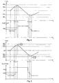
- the Fig. 3 now shows an extended control concept.
- known limit levels are now still an upper and lower alarm level AP O , AP U specified. In practice, these levels will be short, eg 5 cm, below or above the upper and lower maximum levels MP O , MP U
- the level P increases from the time t s0 and reaches at time t s3 . after two switching actions at the times t s1 and t s2 , the upper alarm level AP O.
- the dam is ideally designed so that at this time t s3 all turbine generator units 2 or turbine generator modules 3 are already switched on, so that the maximum flow through the turbines and thus the maximum energy production is achieved.
- an audible alarm is generated in this example, for example, to alert the operating staff to the critical level P.
- this acoustic alarm can also be coupled with an automatic switching action.
- any existing weir systems are opened, whereby the outflowing flow Q A is increased by ⁇ Q W of the weir and the level P begins to decline again.
- the lifting out of the entire turbine generator units 2 or turbine generator modules 3 can also be provided.
- the now decreasing level P reaches the lower turbine switching level TsP U at time t s4 .
- weir systems are still open at this time or not all possibly lifted turbine generator units 2 or turbine generator modules 3 have been lowered into their working position, they should first be closed or lowered before turbine generator units 2 or turbine generator modules 3 are switched off in order to maximize energy production.
- a turbine unit 2 or a turbine generator module 3 is switched off at the time t s4 first a weir system and subsequently at the time t s5 .
- time t s6 now the lower alarm level AP U is reached, in turn triggered an audible alarm and switched off at least one other turbine-generator unit 2 or another turbine generator module 3, so that the level P shows an increasing tendency again.
- the time t s6 if necessary, several or even all still active turbine generator units 2 or turbine generator modules 3 could be switched off at the same time.
- the energy requirement varies greatly over a certain period of time. For example, more energy is consumed during the day than in the evening, or more energy consumed in winter than in summer.
- the method can now be used particularly advantageously if the level P is also optimized with regard to the different requirements for energy generation over a period of time. For example, all superfluous turbine generator units 2 or turbine generator modules 3 can be switched off during the night. As a result, the level P rises over the night, which can then be reduced again in succession to the energy demand peak times of the day by the turbine generator units 2 or turbine generator modules 3 for power generation.
- the optimization is carried out by means of a mathematical model of the dam 1, in which, if necessary, certain other boundary conditions, such as. the temporary opening or closing of additional weir systems, inputs of the operating personnel or meteorological data, can be integrated.
- certain parameters such as e.g. the optimum number of turbine-generator units 2 or turbine-generator modules 3 and / or weir systems to be opened or closed is determined.
Landscapes
- Engineering & Computer Science (AREA)
- General Engineering & Computer Science (AREA)
- Mechanical Engineering (AREA)
- Chemical & Material Sciences (AREA)
- Combustion & Propulsion (AREA)
- Structural Engineering (AREA)
- Civil Engineering (AREA)
- Physics & Mathematics (AREA)
- General Physics & Mathematics (AREA)
- Automation & Control Theory (AREA)
- Hydraulic Turbines (AREA)
- Other Liquid Machine Or Engine Such As Wave Power Use (AREA)
- Control Of Eletrric Generators (AREA)
- Control Of Water Turbines (AREA)
Priority Applications (1)
| Application Number | Priority Date | Filing Date | Title |
|---|---|---|---|
| SI200230867T SI1456533T1 (sl) | 2001-12-20 | 2002-11-26 | Postopek in naprava za reguliranje vodostaja zajezitve |
Applications Claiming Priority (3)
| Application Number | Priority Date | Filing Date | Title |
|---|---|---|---|
| AT0200101A AT411485B (de) | 2001-12-20 | 2001-12-20 | Verfahren und anlage zum regeln des pegelstandes einer stauanlage |
| AT20012001 | 2001-12-20 | ||
| PCT/EP2002/013278 WO2003054387A1 (de) | 2001-12-20 | 2002-11-26 | Verfahren und anlage zum regeln des pegelstandes einer stauanlage |
Publications (2)
| Publication Number | Publication Date |
|---|---|
| EP1456533A1 EP1456533A1 (de) | 2004-09-15 |
| EP1456533B1 true EP1456533B1 (de) | 2009-10-07 |
Family
ID=3689583
Family Applications (1)
| Application Number | Title | Priority Date | Filing Date |
|---|---|---|---|
| EP02805290A Expired - Lifetime EP1456533B1 (de) | 2001-12-20 | 2002-11-26 | Verfahren und anlage zum regeln des pegelstandes einer stauanlage |
Country Status (16)
| Country | Link |
|---|---|
| US (1) | US7067935B2 (pl) |
| EP (1) | EP1456533B1 (pl) |
| AT (2) | AT411485B (pl) |
| AU (1) | AU2002356727A1 (pl) |
| CA (1) | CA2469635C (pl) |
| DE (1) | DE50213908D1 (pl) |
| EG (1) | EG23249A (pl) |
| ES (1) | ES2333853T3 (pl) |
| HU (1) | HU228719B1 (pl) |
| MX (1) | MXPA04005996A (pl) |
| MY (1) | MY135514A (pl) |
| PE (1) | PE20030781A1 (pl) |
| PL (1) | PL205138B1 (pl) |
| PT (1) | PT1456533E (pl) |
| SI (1) | SI1456533T1 (pl) |
| WO (1) | WO2003054387A1 (pl) |
Cited By (1)
| Publication number | Priority date | Publication date | Assignee | Title |
|---|---|---|---|---|
| EP3324219A1 (en) | 2016-11-22 | 2018-05-23 | Uniwersytet Wroclawski | Method for determining an expected inflow to a water reservoir |
Families Citing this family (10)
| Publication number | Priority date | Publication date | Assignee | Title |
|---|---|---|---|---|
| AT510074B1 (de) | 2010-07-14 | 2017-06-15 | Maschf Kba-Mödling Ag | Wasserkraft-staudruckmaschine |
| MX2013008306A (es) | 2011-01-24 | 2013-09-06 | Shell Int Research | Proceso para la produccion de oxido de etileno. |
| EP2668171A1 (en) | 2011-01-24 | 2013-12-04 | Shell Internationale Research Maatschappij B.V. | Process for the production of ethylene oxide |
| CN104093970B (zh) * | 2011-05-16 | 2017-04-12 | 亨利·欧伯梅尔 | 水力机械 |
| DE102011119479A1 (de) | 2011-11-28 | 2013-05-29 | Rwe Technology Gmbh | Verfahren zur Regelung des Strömungsverhaltens von Flüssen |
| DE102011119623A1 (de) | 2011-11-29 | 2013-05-29 | Rwe Technology Gmbh | Laufwasserkraftwerk und Verfahren zur Nutzung der potentiellen Energie zwischen zwei Fließgewässern |
| ES2391207B2 (es) * | 2012-08-30 | 2013-07-10 | Universidad De La Rioja | Procedimiento y dispositivo generador asíncrono para la generación de energía hidroeléctrica |
| EP3051123A1 (en) * | 2015-01-28 | 2016-08-03 | ALSTOM Renewable Technologies | Method for controlling a turbine |
| CN114876706B (zh) * | 2022-04-11 | 2023-05-02 | 浙江大学 | 一种高水头大容量水轮发电机组压力脉动控制方法 |
| CN119913873B (zh) * | 2025-04-02 | 2025-06-17 | 中国电建集团中南勘测设计研究院有限公司 | 一种水库下泄水温调控装置 |
Family Cites Families (41)
| Publication number | Priority date | Publication date | Assignee | Title |
|---|---|---|---|---|
| US3537111A (en) * | 1969-06-25 | 1970-11-03 | George R Whitten Jr | System for controlling water level and recirculation in swimming pools with gutters |
| JPS6032036B2 (ja) * | 1975-08-13 | 1985-07-25 | 株式会社日立製作所 | 発電所の制御装置 |
| CH617247A5 (pl) * | 1977-06-30 | 1980-05-14 | Charmilles Sa Ateliers | |
| US4426846A (en) * | 1978-04-24 | 1984-01-24 | Wayne Bailey | Hydraulic power plant |
| JPS5816205B2 (ja) * | 1978-12-06 | 1983-03-30 | 株式会社日立製作所 | ダム制御方式 |
| CH636736A5 (en) * | 1979-05-23 | 1983-06-15 | Culica Georges Francois | Electricity-generating facility consisting of axial-flow hydroelectric units and of a support barrage |
| US4380419A (en) * | 1981-04-15 | 1983-04-19 | Morton Paul H | Energy collection and storage system |
| US4467216A (en) | 1982-04-06 | 1984-08-21 | J-U-B Engineers, Inc. | Multiple fixed hydraulic geometry turbine control system |
| US4443707A (en) * | 1982-11-19 | 1984-04-17 | Frank Scieri | Hydro electric generating system |
| EP0176576A1 (en) * | 1984-04-10 | 1986-04-09 | Roto Moulded Plastics Pty. Limited | Automatic water level monitoring system |
| SE8404441L (sv) * | 1984-09-05 | 1986-03-06 | Flygt Ab | Sett och anordning for overvakning av vattenturbiner |
| US4674279A (en) * | 1984-09-12 | 1987-06-23 | Acres International Corporation | Control system for run-of-river hydroelectric plant |
| US4607399A (en) * | 1984-09-13 | 1986-08-26 | Trayan Yovanofski | Automatic pool water regulator apparatus |
| US4674216A (en) * | 1985-12-04 | 1987-06-23 | Sturm, Ruger & Company, Inc. | Synthetic material rifle stock with panel inserts |
| US4804855A (en) * | 1987-02-13 | 1989-02-14 | Obermeyer Henry K | Hydromotive machine apparatus and method of constructing the same |
| US4772157A (en) * | 1987-04-16 | 1988-09-20 | Obermeyer Henry K | Liquid level control system and method of operating the same |
| US4787774A (en) * | 1987-07-01 | 1988-11-29 | Grove William M | Fluid control apparatus |
| JPH0673081B2 (ja) * | 1987-11-25 | 1994-09-14 | 株式会社日立製作所 | 自動制御装置 |
| JP2758237B2 (ja) * | 1989-12-21 | 1998-05-28 | 株式会社東芝 | 水力発電所の発電装置 |
| DE4104797A1 (de) | 1991-02-16 | 1992-08-20 | Klein Schanzlin & Becker Ag | Turbinenanlage |
| US5800077A (en) * | 1996-08-19 | 1998-09-01 | Tennessee Valley Authority | Method and apparatus for monitoring a hydroelectric facility trash rack |
| US6269287B1 (en) * | 1996-08-19 | 2001-07-31 | Tennessee Valley Authority | Method and apparatus for monitoring a hydroelectric facility trash rack and optimizing performance |
| WO1998011343A1 (de) * | 1996-09-10 | 1998-03-19 | Voest-Alpine, Machinery Construction & Engineering Gmbh | System von rohrturbinen |
| DE19717871C2 (de) | 1997-04-28 | 2000-04-13 | Mitterfelner Anna | Verfahren zur Steuerung von Turbinensystemen in Wasserkraftwerken |
| US5878447A (en) * | 1997-10-24 | 1999-03-09 | Wkr Productions, Inc. | Automatic water regulator apparatus for filling a swimming pool or comparable body of water when the water level is low |
| US6276200B1 (en) * | 1998-12-23 | 2001-08-21 | Michael L. Cazden | Liquid level controller |
| US6067854A (en) * | 1999-03-31 | 2000-05-30 | Taiwan Semiconductor Manufacturing Company, Ltd. | Apparatus for sensing liquid level |
| US6229448B1 (en) * | 1999-04-12 | 2001-05-08 | Innovative Sensor Solutions, Ltd. | Intrinsically safe fluid tank overfill protection system |
| US6490506B1 (en) * | 1999-05-21 | 2002-12-03 | Hydro Resource Solutions Llc | Method and apparatus for monitoring hydroelectric facility maintenance and environmental costs |
| US6281597B1 (en) * | 1999-08-13 | 2001-08-28 | Syndicated Technologies, Llc. | Hydroelectric installation and method of constructing same |
| US6359347B1 (en) * | 2000-01-03 | 2002-03-19 | Arthur M. Wolf | Siphon hydroelectric generator |
| US6502461B2 (en) * | 2000-02-08 | 2003-01-07 | John M. Keller | Method and apparatus for monitoring liquid level in a container |
| AU2002213220A1 (en) * | 2000-10-30 | 2002-05-15 | Michael L. Cazden | Liquid level controller |
| US6861766B2 (en) * | 2001-12-03 | 2005-03-01 | Peter Rembert | Hydro-electric generating system |
| US6863806B2 (en) * | 2002-04-04 | 2005-03-08 | Lunatech, Llc | Barge-mounted tidal-powered desalinization system |
| US6718567B2 (en) * | 2002-05-29 | 2004-04-13 | Sons Design & Manufacturing, Inc. | Swimming pool water level controller |
| US6997053B2 (en) * | 2003-08-27 | 2006-02-14 | The Boc Group, Inc. | Systems and methods for measurement of low liquid flow rates |
| JP4368729B2 (ja) * | 2004-04-20 | 2009-11-18 | 日立アプライアンス株式会社 | 電気洗濯機 |
| US20050244957A1 (en) * | 2004-04-29 | 2005-11-03 | Healthy Soils, Inc. | Regenerating tank |
| US6978575B1 (en) * | 2004-06-08 | 2005-12-27 | Treg Bradley | Water level regulating plant container |
| JP2006022668A (ja) * | 2004-07-06 | 2006-01-26 | Shin Meiwa Ind Co Ltd | 水中ポンプおよび水中ポンプ装置 |
-
2001
- 2001-12-20 AT AT0200101A patent/AT411485B/de not_active IP Right Cessation
-
2002
- 2002-11-26 AU AU2002356727A patent/AU2002356727A1/en not_active Abandoned
- 2002-11-26 MX MXPA04005996A patent/MXPA04005996A/es active IP Right Grant
- 2002-11-26 EP EP02805290A patent/EP1456533B1/de not_active Expired - Lifetime
- 2002-11-26 SI SI200230867T patent/SI1456533T1/sl unknown
- 2002-11-26 AT AT02805290T patent/ATE445099T1/de active
- 2002-11-26 WO PCT/EP2002/013278 patent/WO2003054387A1/de not_active Ceased
- 2002-11-26 ES ES02805290T patent/ES2333853T3/es not_active Expired - Lifetime
- 2002-11-26 CA CA002469635A patent/CA2469635C/en not_active Expired - Fee Related
- 2002-11-26 PL PL371027A patent/PL205138B1/pl unknown
- 2002-11-26 PT PT02805290T patent/PT1456533E/pt unknown
- 2002-11-26 HU HU0402206A patent/HU228719B1/hu not_active IP Right Cessation
- 2002-11-26 DE DE50213908T patent/DE50213908D1/de not_active Expired - Lifetime
- 2002-12-02 MY MYPI20024520A patent/MY135514A/en unknown
- 2002-12-21 EG EG2002121380A patent/EG23249A/xx active
-
2003
- 2003-01-06 PE PE2003000002A patent/PE20030781A1/es not_active Application Discontinuation
-
2004
- 2004-06-08 US US10/862,431 patent/US7067935B2/en not_active Expired - Fee Related
Cited By (1)
| Publication number | Priority date | Publication date | Assignee | Title |
|---|---|---|---|---|
| EP3324219A1 (en) | 2016-11-22 | 2018-05-23 | Uniwersytet Wroclawski | Method for determining an expected inflow to a water reservoir |
Also Published As
| Publication number | Publication date |
|---|---|
| ES2333853T3 (es) | 2010-03-02 |
| PT1456533E (pt) | 2010-01-12 |
| ATA20012001A (de) | 2003-06-15 |
| US20040247393A1 (en) | 2004-12-09 |
| HU228719B1 (en) | 2013-05-28 |
| PL371027A1 (pl) | 2005-06-13 |
| US7067935B2 (en) | 2006-06-27 |
| AT411485B (de) | 2004-01-26 |
| MXPA04005996A (es) | 2004-09-27 |
| ATE445099T1 (de) | 2009-10-15 |
| SI1456533T1 (sl) | 2010-02-26 |
| AU2002356727A1 (en) | 2003-07-09 |
| PL205138B1 (pl) | 2010-03-31 |
| WO2003054387A1 (de) | 2003-07-03 |
| DE50213908D1 (de) | 2009-11-19 |
| MY135514A (en) | 2008-05-30 |
| HUP0402206A2 (hu) | 2005-02-28 |
| CA2469635C (en) | 2008-07-22 |
| CA2469635A1 (en) | 2003-07-03 |
| EP1456533A1 (de) | 2004-09-15 |
| PE20030781A1 (es) | 2003-11-26 |
| EG23249A (en) | 2004-09-29 |
Similar Documents
| Publication | Publication Date | Title |
|---|---|---|
| EP1456533B1 (de) | Verfahren und anlage zum regeln des pegelstandes einer stauanlage | |
| WO2020079000A1 (de) | Verfahren und windpark zum einspeisen elektrischer leistung in ein elektrisches versorgungsnetz | |
| EP2017469B1 (de) | Verfahren zum Betreiben einer Windenergieanlage | |
| WO2017093426A1 (de) | Verfahren und vorrichtung zum einbringen und zur entnahme von wärmeenergie in bzw. aus einem gewässer | |
| DE20121214U1 (de) | Wasserkraftwerk | |
| DE102012008876A1 (de) | Off-Shore-Pumpspeicher-Kraftwerk | |
| WO2015018613A1 (de) | Verfahren zum steuern von windenergieanlagen | |
| WO2009052968A1 (de) | Anordnung und verfahren zum betreiben einer windenergieanlage oder eines windparks | |
| EP1455087B1 (de) | Verfahren zum Umbau einer Anlage mit Rohrturbinen | |
| EP1447627B1 (de) | Vorrichtung zum Steuern und/oder Regeln für die Gebäudeheizung oder -kühlung | |
| WO2016139082A1 (de) | Verfahren zum betreiben einer windenergieanlage | |
| WO2020109300A1 (de) | Anordnung mit speicher für elektrische energie und regenerativen energieerzeuger, insbesondere wea, sowie verfahren zu deren betrieb | |
| EP2853728B1 (de) | Verfahren zur Speicherung von elektrischer Energie in einem natürlichen Speicher | |
| EP3983674A1 (de) | Verfahren und windenergieanlage zum erfassen einer windgeschwindigkeit | |
| DE102012022096B4 (de) | Verfahren zur Speicherung von elektrischer Energie in einem natürlichen Speicher | |
| WO2020212206A1 (de) | Verfahren zur steuerung einer kühleinrichtung einer photovoltaikanlage sowie photovoltaikanlage mit einer kühleinrichtung | |
| DE202023100781U1 (de) | Kleinspeicherkraftwerke zur Energiespeicherung | |
| WO2012025389A1 (de) | Ausdehnungssystem des wärmeträgermedium-kreislaufes eines solarthermischen kraftwerks | |
| DE19824543C5 (de) | Verfahren zur Regelung von Umwälzpumpen in den Solarkollektorkreisen von Solaranlagen mit Speicher | |
| EP4022731B1 (de) | Verfahren zum betreiben einer elektrischen speicherstation | |
| EP2817507A1 (de) | Kraftwerk | |
| DE202018000353U1 (de) | Wasserwerk | |
| WO2019234465A1 (de) | Vorrichtung und verfahren zur vorbeugung gegen überschwemmungen | |
| DE102022200570A1 (de) | Verfahren und Windkraftanlagensystem zur Beeinflussung einer Wetterlage | |
| EP4022177A1 (de) | Verfahren zur regelung der eintrittstemperatur eines arbeitsfluides einer dampfturbine bei schwankender bereitstellung thermischer energie |
Legal Events
| Date | Code | Title | Description |
|---|---|---|---|
| PUAI | Public reference made under article 153(3) epc to a published international application that has entered the european phase |
Free format text: ORIGINAL CODE: 0009012 |
|
| 17P | Request for examination filed |
Effective date: 20040428 |
|
| AK | Designated contracting states |
Kind code of ref document: A1 Designated state(s): AT BE BG CH CY CZ DE DK EE ES FI FR GB GR IE IT LI LU MC NL PT SE SK TR |
|
| AX | Request for extension of the european patent |
Extension state: AL LT LV MK RO SI |
|
| RAP1 | Party data changed (applicant data changed or rights of an application transferred) |
Owner name: VA TECH HYDRO GMBH |
|
| GRAP | Despatch of communication of intention to grant a patent |
Free format text: ORIGINAL CODE: EPIDOSNIGR1 |
|
| GRAS | Grant fee paid |
Free format text: ORIGINAL CODE: EPIDOSNIGR3 |
|
| GRAA | (expected) grant |
Free format text: ORIGINAL CODE: 0009210 |
|
| RAP1 | Party data changed (applicant data changed or rights of an application transferred) |
Owner name: ANDRITZ HYDRO GMBH |
|
| AK | Designated contracting states |
Kind code of ref document: B1 Designated state(s): AT BE BG CH CY CZ DE DK EE ES FI FR GB GR IE IT LI LU MC NL PT SE SK TR |
|
| AX | Request for extension of the european patent |
Extension state: AL LT LV MK RO SI |
|
| REG | Reference to a national code |
Ref country code: GB Ref legal event code: FG4D Free format text: NOT ENGLISH |
|
| REG | Reference to a national code |
Ref country code: CH Ref legal event code: EP |
|
| REG | Reference to a national code |
Ref country code: IE Ref legal event code: FG4D |
|
| REF | Corresponds to: |
Ref document number: 50213908 Country of ref document: DE Date of ref document: 20091119 Kind code of ref document: P |
|
| REG | Reference to a national code |
Ref country code: PT Ref legal event code: SC4A Free format text: AVAILABILITY OF NATIONAL TRANSLATION Effective date: 20100104 |
|
| REG | Reference to a national code |
Ref country code: GR Ref legal event code: EP Ref document number: 20090403280 Country of ref document: GR |
|
| NLV1 | Nl: lapsed or annulled due to failure to fulfill the requirements of art. 29p and 29m of the patents act | ||
| REG | Reference to a national code |
Ref country code: ES Ref legal event code: FG2A Ref document number: 2333853 Country of ref document: ES Kind code of ref document: T3 |
|
| LTIE | Lt: invalidation of european patent or patent extension |
Effective date: 20091007 |
|
| PG25 | Lapsed in a contracting state [announced via postgrant information from national office to epo] |
Ref country code: SE Free format text: LAPSE BECAUSE OF FAILURE TO SUBMIT A TRANSLATION OF THE DESCRIPTION OR TO PAY THE FEE WITHIN THE PRESCRIBED TIME-LIMIT Effective date: 20091007 |
|
| REG | Reference to a national code |
Ref country code: IE Ref legal event code: FD4D |
|
| BERE | Be: lapsed |
Owner name: ANDRITZ HYDRO GMBH Effective date: 20091130 |
|
| PG25 | Lapsed in a contracting state [announced via postgrant information from national office to epo] |
Ref country code: MC Free format text: LAPSE BECAUSE OF NON-PAYMENT OF DUE FEES Effective date: 20091130 |
|
| REG | Reference to a national code |
Ref country code: CH Ref legal event code: PL |
|
| PG25 | Lapsed in a contracting state [announced via postgrant information from national office to epo] |
Ref country code: EE Free format text: LAPSE BECAUSE OF FAILURE TO SUBMIT A TRANSLATION OF THE DESCRIPTION OR TO PAY THE FEE WITHIN THE PRESCRIBED TIME-LIMIT Effective date: 20091007 Ref country code: NL Free format text: LAPSE BECAUSE OF FAILURE TO SUBMIT A TRANSLATION OF THE DESCRIPTION OR TO PAY THE FEE WITHIN THE PRESCRIBED TIME-LIMIT Effective date: 20091007 Ref country code: DK Free format text: LAPSE BECAUSE OF FAILURE TO SUBMIT A TRANSLATION OF THE DESCRIPTION OR TO PAY THE FEE WITHIN THE PRESCRIBED TIME-LIMIT Effective date: 20091007 Ref country code: IE Free format text: LAPSE BECAUSE OF FAILURE TO SUBMIT A TRANSLATION OF THE DESCRIPTION OR TO PAY THE FEE WITHIN THE PRESCRIBED TIME-LIMIT Effective date: 20091007 Ref country code: BG Free format text: LAPSE BECAUSE OF FAILURE TO SUBMIT A TRANSLATION OF THE DESCRIPTION OR TO PAY THE FEE WITHIN THE PRESCRIBED TIME-LIMIT Effective date: 20100107 |
|
| PLBE | No opposition filed within time limit |
Free format text: ORIGINAL CODE: 0009261 |
|
| STAA | Information on the status of an ep patent application or granted ep patent |
Free format text: STATUS: NO OPPOSITION FILED WITHIN TIME LIMIT |
|
| PG25 | Lapsed in a contracting state [announced via postgrant information from national office to epo] |
Ref country code: SK Free format text: LAPSE BECAUSE OF FAILURE TO SUBMIT A TRANSLATION OF THE DESCRIPTION OR TO PAY THE FEE WITHIN THE PRESCRIBED TIME-LIMIT Effective date: 20091007 |
|
| 26N | No opposition filed |
Effective date: 20100708 |
|
| PG25 | Lapsed in a contracting state [announced via postgrant information from national office to epo] |
Ref country code: CH Free format text: LAPSE BECAUSE OF NON-PAYMENT OF DUE FEES Effective date: 20091130 Ref country code: LI Free format text: LAPSE BECAUSE OF NON-PAYMENT OF DUE FEES Effective date: 20091130 Ref country code: BE Free format text: LAPSE BECAUSE OF NON-PAYMENT OF DUE FEES Effective date: 20091130 |
|
| PG25 | Lapsed in a contracting state [announced via postgrant information from national office to epo] |
Ref country code: LU Free format text: LAPSE BECAUSE OF NON-PAYMENT OF DUE FEES Effective date: 20091126 |
|
| PG25 | Lapsed in a contracting state [announced via postgrant information from national office to epo] |
Ref country code: TR Free format text: LAPSE BECAUSE OF FAILURE TO SUBMIT A TRANSLATION OF THE DESCRIPTION OR TO PAY THE FEE WITHIN THE PRESCRIBED TIME-LIMIT Effective date: 20091007 |
|
| PG25 | Lapsed in a contracting state [announced via postgrant information from national office to epo] |
Ref country code: CY Free format text: LAPSE BECAUSE OF FAILURE TO SUBMIT A TRANSLATION OF THE DESCRIPTION OR TO PAY THE FEE WITHIN THE PRESCRIBED TIME-LIMIT Effective date: 20091007 |
|
| PGFP | Annual fee paid to national office [announced via postgrant information from national office to epo] |
Ref country code: GB Payment date: 20141119 Year of fee payment: 13 Ref country code: CZ Payment date: 20141121 Year of fee payment: 13 |
|
| PGFP | Annual fee paid to national office [announced via postgrant information from national office to epo] |
Ref country code: PT Payment date: 20141124 Year of fee payment: 13 |
|
| REG | Reference to a national code |
Ref country code: FR Ref legal event code: PLFP Year of fee payment: 14 |
|
| PGFP | Annual fee paid to national office [announced via postgrant information from national office to epo] |
Ref country code: FI Payment date: 20151111 Year of fee payment: 14 Ref country code: DE Payment date: 20151119 Year of fee payment: 14 Ref country code: IT Payment date: 20151125 Year of fee payment: 14 Ref country code: GR Payment date: 20151112 Year of fee payment: 14 |
|
| PGFP | Annual fee paid to national office [announced via postgrant information from national office to epo] |
Ref country code: FR Payment date: 20151119 Year of fee payment: 14 Ref country code: ES Payment date: 20151111 Year of fee payment: 14 Ref country code: AT Payment date: 20151119 Year of fee payment: 14 |
|
| REG | Reference to a national code |
Ref country code: PT Ref legal event code: MM4A Free format text: LAPSE DUE TO NON-PAYMENT OF FEES Effective date: 20160527 |
|
| GBPC | Gb: european patent ceased through non-payment of renewal fee |
Effective date: 20151126 |
|
| PG25 | Lapsed in a contracting state [announced via postgrant information from national office to epo] |
Ref country code: CZ Free format text: LAPSE BECAUSE OF NON-PAYMENT OF DUE FEES Effective date: 20151126 |
|
| PG25 | Lapsed in a contracting state [announced via postgrant information from national office to epo] |
Ref country code: PT Free format text: LAPSE BECAUSE OF NON-PAYMENT OF DUE FEES Effective date: 20160527 |
|
| REG | Reference to a national code |
Ref country code: SI Ref legal event code: KO00 Effective date: 20160712 |
|
| PG25 | Lapsed in a contracting state [announced via postgrant information from national office to epo] |
Ref country code: GB Free format text: LAPSE BECAUSE OF NON-PAYMENT OF DUE FEES Effective date: 20151126 |
|
| REG | Reference to a national code |
Ref country code: DE Ref legal event code: R119 Ref document number: 50213908 Country of ref document: DE |
|
| REG | Reference to a national code |
Ref country code: AT Ref legal event code: MM01 Ref document number: 445099 Country of ref document: AT Kind code of ref document: T Effective date: 20161126 |
|
| PG25 | Lapsed in a contracting state [announced via postgrant information from national office to epo] |
Ref country code: GR Free format text: LAPSE BECAUSE OF NON-PAYMENT OF DUE FEES Effective date: 20170612 Ref country code: FI Free format text: LAPSE BECAUSE OF NON-PAYMENT OF DUE FEES Effective date: 20161126 |
|
| REG | Reference to a national code |
Ref country code: FR Ref legal event code: ST Effective date: 20170731 |
|
| PG25 | Lapsed in a contracting state [announced via postgrant information from national office to epo] |
Ref country code: AT Free format text: LAPSE BECAUSE OF NON-PAYMENT OF DUE FEES Effective date: 20161126 |
|
| PG25 | Lapsed in a contracting state [announced via postgrant information from national office to epo] |
Ref country code: FR Free format text: LAPSE BECAUSE OF NON-PAYMENT OF DUE FEES Effective date: 20161130 Ref country code: IT Free format text: LAPSE BECAUSE OF NON-PAYMENT OF DUE FEES Effective date: 20161126 |
|
| PG25 | Lapsed in a contracting state [announced via postgrant information from national office to epo] |
Ref country code: DE Free format text: LAPSE BECAUSE OF NON-PAYMENT OF DUE FEES Effective date: 20170601 |
|
| PG25 | Lapsed in a contracting state [announced via postgrant information from national office to epo] |
Ref country code: ES Free format text: LAPSE BECAUSE OF NON-PAYMENT OF DUE FEES Effective date: 20161127 |
|
| REG | Reference to a national code |
Ref country code: ES Ref legal event code: FD2A Effective date: 20180626 |