EP1456533B1 - Method and system for regulating the level of a dam - Google Patents
Method and system for regulating the level of a dam Download PDFInfo
- Publication number
- EP1456533B1 EP1456533B1 EP02805290A EP02805290A EP1456533B1 EP 1456533 B1 EP1456533 B1 EP 1456533B1 EP 02805290 A EP02805290 A EP 02805290A EP 02805290 A EP02805290 A EP 02805290A EP 1456533 B1 EP1456533 B1 EP 1456533B1
- Authority
- EP
- European Patent Office
- Prior art keywords
- turbine
- generator
- dam
- process according
- plant
- Prior art date
- Legal status (The legal status is an assumption and is not a legal conclusion. Google has not performed a legal analysis and makes no representation as to the accuracy of the status listed.)
- Expired - Lifetime
Links
Images

Classifications
-
- F—MECHANICAL ENGINEERING; LIGHTING; HEATING; WEAPONS; BLASTING
- F03—MACHINES OR ENGINES FOR LIQUIDS; WIND, SPRING, OR WEIGHT MOTORS; PRODUCING MECHANICAL POWER OR A REACTIVE PROPULSIVE THRUST, NOT OTHERWISE PROVIDED FOR
- F03B—MACHINES OR ENGINES FOR LIQUIDS
- F03B15/00—Controlling
- F03B15/02—Controlling by varying liquid flow
- F03B15/04—Controlling by varying liquid flow of turbines
- F03B15/06—Regulating, i.e. acting automatically
- F03B15/14—Regulating, i.e. acting automatically by or of water level
-
- E—FIXED CONSTRUCTIONS
- E02—HYDRAULIC ENGINEERING; FOUNDATIONS; SOIL SHIFTING
- E02B—HYDRAULIC ENGINEERING
- E02B9/00—Water-power plants; Layout, construction or equipment, methods of, or apparatus for, making same
-
- F—MECHANICAL ENGINEERING; LIGHTING; HEATING; WEAPONS; BLASTING
- F03—MACHINES OR ENGINES FOR LIQUIDS; WIND, SPRING, OR WEIGHT MOTORS; PRODUCING MECHANICAL POWER OR A REACTIVE PROPULSIVE THRUST, NOT OTHERWISE PROVIDED FOR
- F03B—MACHINES OR ENGINES FOR LIQUIDS
- F03B13/00—Adaptations of machines or engines for special use; Combinations of machines or engines with driving or driven apparatus; Power stations or aggregates
- F03B13/08—Machine or engine aggregates in dams or the like; Conduits therefor, e.g. diffusors
-
- F—MECHANICAL ENGINEERING; LIGHTING; HEATING; WEAPONS; BLASTING
- F03—MACHINES OR ENGINES FOR LIQUIDS; WIND, SPRING, OR WEIGHT MOTORS; PRODUCING MECHANICAL POWER OR A REACTIVE PROPULSIVE THRUST, NOT OTHERWISE PROVIDED FOR
- F03B—MACHINES OR ENGINES FOR LIQUIDS
- F03B13/00—Adaptations of machines or engines for special use; Combinations of machines or engines with driving or driven apparatus; Power stations or aggregates
- F03B13/10—Submerged units incorporating electric generators or motors
- F03B13/105—Bulb groups
-
- G—PHYSICS
- G05—CONTROLLING; REGULATING
- G05D—SYSTEMS FOR CONTROLLING OR REGULATING NON-ELECTRIC VARIABLES
- G05D9/00—Level control, e.g. controlling quantity of material stored in vessel
- G05D9/12—Level control, e.g. controlling quantity of material stored in vessel characterised by the use of electric means
-
- F—MECHANICAL ENGINEERING; LIGHTING; HEATING; WEAPONS; BLASTING
- F05—INDEXING SCHEMES RELATING TO ENGINES OR PUMPS IN VARIOUS SUBCLASSES OF CLASSES F01-F04
- F05B—INDEXING SCHEME RELATING TO WIND, SPRING, WEIGHT, INERTIA OR LIKE MOTORS, TO MACHINES OR ENGINES FOR LIQUIDS COVERED BY SUBCLASSES F03B, F03D AND F03G
- F05B2240/00—Components
- F05B2240/40—Use of a multiplicity of similar components
-
- Y—GENERAL TAGGING OF NEW TECHNOLOGICAL DEVELOPMENTS; GENERAL TAGGING OF CROSS-SECTIONAL TECHNOLOGIES SPANNING OVER SEVERAL SECTIONS OF THE IPC; TECHNICAL SUBJECTS COVERED BY FORMER USPC CROSS-REFERENCE ART COLLECTIONS [XRACs] AND DIGESTS
- Y02—TECHNOLOGIES OR APPLICATIONS FOR MITIGATION OR ADAPTATION AGAINST CLIMATE CHANGE
- Y02E—REDUCTION OF GREENHOUSE GAS [GHG] EMISSIONS, RELATED TO ENERGY GENERATION, TRANSMISSION OR DISTRIBUTION
- Y02E10/00—Energy generation through renewable energy sources
- Y02E10/20—Hydro energy
Definitions
- the invention relates to a method for regulating the level of a reservoir, preferably a dam or weir, wherein in the reservoir for generating electrical energy, a number of turbine-generator units, preferably with powers between 100kW and 1000kW, are arranged, at least in sections one above the other and / or arranged side by side and connected to one or more turbine-generator modules, and a system for regulating the level of a reservoir with a plurality of turbine-generator units, which are arranged one above the other and / or next to each other and to each other one or more turbine-generator modules are connected and optionally a predetermined number of turbine-generator modules are arranged side by side and supported on the dam.
- Devices for generating electrical energy in which a plurality of smaller turbine generator units are arranged in rows and columns next to each other and one above the other in a frame or a stiffened construction, are for example from WO98 / 11343 , of the US 6,281,597 B1 or the US 4,804,855 A known.
- Such facilities are due to their particularly short design and large inflow preferably od on dams, such as locks, weirs, dams. The like., Used to use the usual way unused flowing water to generate electrical energy.
- dams Used to use the usual way unused flowing water to generate electrical energy.
- the water level must be regulated in order to meet the required function of the dam according to the application. For example, shipping on a river requires a certain level of water, or an irrigation dam must have a minimum water level to ensure irrigation. For this purpose, weir system was opened in whole or in part.
- the invention has now taken on the task of specifying a method for controlling the level of a reservoir that largely exploits the existing possibilities and structural conditions, ensures the function of the dam and ensures a simple and accurate control.
- the level is at least partially controlled by the supply or disconnection of individual or multiple turbine-generator units or turbine-generator modules to a predetermined setpoint, with a flow through the reservoir in discrete steps is set and corresponds to a discrete step of flowable through one or more turbine-generator unit flow rate.
- These turbine generator units or turbine generator modules have one exactly known flow, whereby the outflowing flow rate can be accurately determined.
- the effluent flow rate and consequently also the level of the accumulation system can therefore be controlled very simply and precisely by means of the individual turbine units in small discrete steps. It is therefore necessary only in exceptional situations, which usually open very large, heavy and poorly regulated weir systems or close. This makes the control more flexible as it allows the control to be made in small increments and moreover allows a rapid response to changing conditions at the dam.
- the level can be very easily optimized with regard to certain criteria.
- the turbine-generator units or turbine-generator modules used to control the level can be structurally very simple, if these units or modules are operated at a substantially constant flow rate or constant power, then no means for regulating the Flow rate or the power must be provided.
- the units or turbines thus have only two operating points, namely in operation or out of service, which also simplifies the scheme considerably.
- the outflowing flow rate can be increased rapidly. This is particularly useful as a safety measure, in situations where the flow through the turbine units is no longer sufficient to reduce the inflowing water again, or where the drain from the dam must be reduced rapidly.
- the generation of electrical energy by the turbine units can be maximized when first all turbine generator units or turbine generator modules are switched on and only then weir system are opened. Likewise one achieves a maximization of the production of electrical energy, if first all weir plants be opened and only then turbine-generator units or turbine-generator modules are switched off. Through these measures, the flow through the turbine units is maximized, which has a direct positive effect on the amount of energy generated.
- alarm signals are generated and / or displayed upon reaching a given turbine switching level and / or alarm level, since then the current critical situation can be reacted immediately and without a time delay.
- alarm signals may e.g. be acoustic and / or optical nature.
- a further advantageous extension of the control concept can be achieved if the number of turbine generator units or turbine generator modules to be connected or disconnected are determined in advance and simultaneously switched on or off, since then the time required to correct the water level Switching operations can be performed in one go. It is favorable to determine the number of turbine generators or turbine generator modules to be connected or disconnected on the basis of the current energy requirement and possibly also on the basis of a future expected water level, which results in an optimal utilization with regard to the energy requirement Units or modules reached.
- the optimization is carried out very advantageously with the help of a mathematical model, the conditions to improve the optimization results certain conditions and boundary conditions, such as the temporary opening or closing of weirs, dams, locks and possibly the lifting of turbine-generator or turbine generator -Modules, inputs of the operating personnel, stored empirical values, physical laws, such as the evaporating or infiltrating amount of water, etc., and current or forward-looking meteorological data, such as expected rainfall, temperature forecasts, etc., taken into account.
- conditions and boundary conditions such as the temporary opening or closing of weirs, dams, locks and possibly the lifting of turbine-generator or turbine generator -Modules, inputs of the operating personnel, stored empirical values, physical laws, such as the evaporating or infiltrating amount of water, etc., and current or forward-looking meteorological data, such as expected rainfall, temperature forecasts, etc., taken into account.
- the optimum number of turbine / generator units or turbine generator to be switched on or off can be very advantageously based on the mathematical model taking into account the current and / or expected inflow or outflow and the current and / or expected energy requirement Modules are determined.
- the set point for the control is advantageously the level over a predetermined period of time, such as a year, used.
- the energy to be generated can be specified over a certain time range, preferably one day, and the level can be regulated so that the predetermined power generation curve can be maintained as accurately as possible. This achieves optimum utilization of energy while ensuring the actual functioning of the dam. At the same time, this ensures that the resources of the dam are utilized as much as possible.
- water levels of one or more dams can be controlled from a central control center, additional on-site monitoring and control equipment can be saved, which has a very positive effect on the costs.
- the target value for the water level is specified for a purpose other than power generation, e.g. for shipping, irrigation, etc., the originally intended operation of the dam is not affected.
- the energy is then an additional advantage that can be achieved without any restrictions on the operation.
- the dam has a plurality of pillars, between which the medium can flow past, wherein between two adjacent pillars a predetermined number of turbine-generator units or turbine-generator modules are arranged and supported on the pillars. This already allows existing structures of the dam are used directly for retrofitting and there are no costly remodeling necessary.
- a very compact embodiment is obtained by integrating the means for connecting and disconnecting turbine-generator units or turbine-generator modules in the units or modules and being supported on the pillars via the unit or the module. This also minimizes the necessary structural measures at the dam.
- Another variant provides that the device for connecting and disconnecting turbine-generator units or turbine-generator modules is supported directly on the pillars.
- the turbine generator units or turbine generator modules can be easily removed from their working position, e.g. for maintenance or to release the Strömungsquerschittes in certain situations when they are arranged raised and lowered.
- a very particularly advantageous application is the regulation according to the invention of the level of a dam in a drinking water reservoir, an irrigation dam, a flood retention basin, a dam to regulate a shipping route or a barrage of a river power plant.
- the Fig. 1 shows schematically and simplifies a dam 1, for example, a dam, for damming a liquid, preferably water in a river, with in this embodiment two pillars 4, between which a number of turbine-generator units 2, here ten, are arranged. These turbine-generator units 2 are supported and held by the pillars 4. The turbine-generator units 2 are combined to form a turbine generator module 3 and can be lifted out of the reservoir 1 as a module with a lifting device, not shown.
- the reservoir 1 may comprise a weir system, not shown, with which the outflow of the medium from the reservoir 1 can be fully or partially released or prevented.
- the turbine-generator units 2 can be used in a manner known per se, for example by a suction tube closure, such as a sheet or an iris diaphragm, individually, or in groups, such as the entire turbine-generator module 3, are sealed off, so that no water can flow through the turbine-generator units 2 and consequently no electric current is generated by these units.
- a suction tube closure such as a sheet or an iris diaphragm
- such a dam can also comprise more than two pillars and that between two pillars more than those in Fig. 1 illustrated turbine generator units 2 can be arranged.
- any number of such turbine generator units 2, preferably 20 to 500, in a dam can also be used in any other than in Fig. 1 described dams, such as drinking water reservoirs, irrigation dams, flood retention basins, etc., can be used, the control concept described below for the water level level of the same type can be applied.
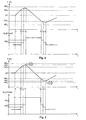
- Fig. 2 the basic principle of the control concept according to the invention of the level of any congestion plant with integrated turbine-generator units 2 discussed.
- Fig. 2 two diagrams are shown, the first shows the water level P over the time t and the second shows the effluent from the accumulation flow rate Q A over the time t.
- a target level ZP is specified for the dam.
- the current level P may now vary within likewise predetermined upper and lower turbine switching levels TsP O , TsP U. These levels result from the requirements of the dam, for example, the shipping traffic on a river requires certain minimum and maximum water levels.
- upper and lower maximum levels MP O , MP U are set for the accumulation plant, which must not be exceeded or fallen short of. Should these maximum levels be exceeded or fallen short of in exceptional situations, depending on the dam, certain emergency measures, such as shutting off or opening further upstream dams, the opening of existing emergency locks, the lifting of the turbine-generator units 2 or - modules 3, etc ., be initiated.
- the starting point of the description of the control method is a state in which the inflow and outflow quantities are equal and the level P does not change. In this state, any number of turbine-generator units 2 or turbine-generator modules 3 are already open, so that a certain amount of water Q A flows through these units and electrical energy is generated.
- the level P of the storage system now rises, for example due to rainfall, starting from the target level ZP and reaches the upper turbine switching level TsP 0 at the instant t s1 .
- t s1 is automatically or by the operator one or more other individual turbine-generator units 2 or Turbine generator modules 3 connected to increase the outflow rate Q A.
- This increase in the discharge rate is a discrete increase ⁇ Q TE , or a multiple thereof, and corresponds exactly to that amount of water that is flowable through the turbine-generator unit or turbine-generator modules.
- TsP U can further an alarm is triggered, which is displayed for example in a control center or by an audible signal and the operating personnel draws attention to the present situation, or triggers an automatic switching operation.
- the Fig. 3 now shows an extended control concept.
- known limit levels are now still an upper and lower alarm level AP O , AP U specified. In practice, these levels will be short, eg 5 cm, below or above the upper and lower maximum levels MP O , MP U
- the level P increases from the time t s0 and reaches at time t s3 . after two switching actions at the times t s1 and t s2 , the upper alarm level AP O.
- the dam is ideally designed so that at this time t s3 all turbine generator units 2 or turbine generator modules 3 are already switched on, so that the maximum flow through the turbines and thus the maximum energy production is achieved.
- an audible alarm is generated in this example, for example, to alert the operating staff to the critical level P.
- this acoustic alarm can also be coupled with an automatic switching action.
- any existing weir systems are opened, whereby the outflowing flow Q A is increased by ⁇ Q W of the weir and the level P begins to decline again.
- the lifting out of the entire turbine generator units 2 or turbine generator modules 3 can also be provided.
- the now decreasing level P reaches the lower turbine switching level TsP U at time t s4 .
- weir systems are still open at this time or not all possibly lifted turbine generator units 2 or turbine generator modules 3 have been lowered into their working position, they should first be closed or lowered before turbine generator units 2 or turbine generator modules 3 are switched off in order to maximize energy production.
- a turbine unit 2 or a turbine generator module 3 is switched off at the time t s4 first a weir system and subsequently at the time t s5 .
- time t s6 now the lower alarm level AP U is reached, in turn triggered an audible alarm and switched off at least one other turbine-generator unit 2 or another turbine generator module 3, so that the level P shows an increasing tendency again.
- the time t s6 if necessary, several or even all still active turbine generator units 2 or turbine generator modules 3 could be switched off at the same time.
- the energy requirement varies greatly over a certain period of time. For example, more energy is consumed during the day than in the evening, or more energy consumed in winter than in summer.
- the method can now be used particularly advantageously if the level P is also optimized with regard to the different requirements for energy generation over a period of time. For example, all superfluous turbine generator units 2 or turbine generator modules 3 can be switched off during the night. As a result, the level P rises over the night, which can then be reduced again in succession to the energy demand peak times of the day by the turbine generator units 2 or turbine generator modules 3 for power generation.
- the optimization is carried out by means of a mathematical model of the dam 1, in which, if necessary, certain other boundary conditions, such as. the temporary opening or closing of additional weir systems, inputs of the operating personnel or meteorological data, can be integrated.
- certain parameters such as e.g. the optimum number of turbine-generator units 2 or turbine-generator modules 3 and / or weir systems to be opened or closed is determined.
Landscapes
- Engineering & Computer Science (AREA)
- General Engineering & Computer Science (AREA)
- Mechanical Engineering (AREA)
- Chemical & Material Sciences (AREA)
- Combustion & Propulsion (AREA)
- General Physics & Mathematics (AREA)
- Physics & Mathematics (AREA)
- Automation & Control Theory (AREA)
- Civil Engineering (AREA)
- Structural Engineering (AREA)
- Hydraulic Turbines (AREA)
- Other Liquid Machine Or Engine Such As Wave Power Use (AREA)
- Control Of Eletrric Generators (AREA)
- Control Of Water Turbines (AREA)
Description
Die Erfindung betrifft ein Verfahren zum Regeln des Pegelstandes einer Stauanlage, vorzugsweise ein Staudamm oder ein Stauwehr, wobei in der Stauanlage zum Erzeugen elektrischer Energie eine Anzahl von Turbinen-Generator-Einheiten, vorzugsweise mit Leistungen zwischen je 100kW und 1000kW, angeordnet sind, die zumindest abschnittsweise übereinander und/oder nebeneinander angeordnet und miteinander zu einem oder mehreren Turbinen-Generator-Modulen verbunden sind, sowie eine Anlage zum Regeln des Pegelstandes einer Stauanlage mit einer Mehrzahl von Turbinen-Generator-Einheiten, die übereinander und/oder nebeneinander angeordnet und miteinander zu einem oder mehreren Turbinen-Generator-Modulen verbunden sind und gegebenenfalls eine vorbestimmte Anzahl von Turbinen-Generator-Modulen nebeneinander angeordnet und an der Stauanlage abgestützt sind.The invention relates to a method for regulating the level of a reservoir, preferably a dam or weir, wherein in the reservoir for generating electrical energy, a number of turbine-generator units, preferably with powers between 100kW and 1000kW, are arranged, at least in sections one above the other and / or arranged side by side and connected to one or more turbine-generator modules, and a system for regulating the level of a reservoir with a plurality of turbine-generator units, which are arranged one above the other and / or next to each other and to each other one or more turbine-generator modules are connected and optionally a predetermined number of turbine-generator modules are arranged side by side and supported on the dam.
Einrichtungen zur Erzeugung elektrischer Energie, bei welchen mehrere kleinere Turbinen-Generatoreinheiten in Reihen und Spalten nebeneinander und übereinander in einem Rahmen oder einer versteiften Konstruktion angeordnet sind, sind beispielsweise aus der
Ebenso sind bereits Regelungen von Wasserkraftanlagen bekannt, wobei diese Regelungen die Maximierung oder die Optimierung der erzeugten Energie anstreben. Dazu sind die Turbinen solcher Wasserkraftanlagen mit kontinuierlich einstellbaren Regeleinrichtungen, wie z.B. Leitschaufeln, ausgestattet, um den Volumenstrom durch die Turbine und damit die erzeugte Leistung kontinuierlich regeln zu können.
Die
The
Die Erfindung hat sich nun die Aufgabe gestellt, ein Verfahren zur Regelung des Pegelstandes einer Stauanlage anzugeben, dass die vorhandenen Möglichkeiten und bauliche Gegebenheiten weitestgehend ausnützt, die Funktion der Stauanlage sicherstellt und eine einfache und genaue Regelung ermöglicht.The invention has now taken on the task of specifying a method for controlling the level of a reservoir that largely exploits the existing possibilities and structural conditions, ensures the function of the dam and ensures a simple and accurate control.
Diese Aufgabe wird erfindungsgemäß dadurch gelöst, dass der Pegelstand zumindest teilweise durch das Zu- bzw. Wegschalten von einzelnen oder mehreren Turbinen-Generator-Einheiten oder Turbinen-Generator-Modulen auf einen vorgebbaren Sollwert geregelt wird, wobei eine Durchflussmenge durch die Stauanlage in diskreten Schritten eingestellt wird und ein diskreter Schritt der durch eine bzw. mehrere Turbinen-Generator-Einheit fließbaren Durchflussmenge entspricht.
Diese Turbinen-Generator-Einheiten oder Turbinen-Generator-Module haben einen genau bekannten Durchfluss, wodurch die abfließende Durchflussmenge genau bestimmt werden kann. Die abfließende Durchflussmenge und folglich auch der Pegelstand der Stauanlage kann deshalb mittels der einzelnen Turbineneinheiten in kleinen diskreten Schritten sehr einfach und genau geregelt werden. Es ist somit nur mehr in Ausnahmesituationen notwendig, die in der Regel sehr großen, schweren und schlecht regelbaren Wehranlagen zu öffnen bzw. zu schließen.
Die Regelung wird dadurch flexibler, da dadurch die Regelung in kleinen Schritten ermöglicht wird und erlaubt darüber hinaus eine rasche Reaktion auf sich ändernde Bedingungen an der Stauanlage. Weiters lässt sich dadurch der Pegelstand hinsichtlich bestimmter Kriterien sehr einfach optimieren.This object is achieved in that the level is at least partially controlled by the supply or disconnection of individual or multiple turbine-generator units or turbine-generator modules to a predetermined setpoint, with a flow through the reservoir in discrete steps is set and corresponds to a discrete step of flowable through one or more turbine-generator unit flow rate.
These turbine generator units or turbine generator modules have one exactly known flow, whereby the outflowing flow rate can be accurately determined. The effluent flow rate and consequently also the level of the accumulation system can therefore be controlled very simply and precisely by means of the individual turbine units in small discrete steps. It is therefore necessary only in exceptional situations, which usually open very large, heavy and poorly regulated weir systems or close.
This makes the control more flexible as it allows the control to be made in small increments and moreover allows a rapid response to changing conditions at the dam. Furthermore, the level can be very easily optimized with regard to certain criteria.
Die zur Regelung des Pegelstandes verwendeten Turbinen-Generator-Einheiten oder Turbinen-Generator-Module können konstruktiv sehr einfach ausgeführt werden, wenn diese Einheiten bzw. Module bei im wesentlichen konstanter Durchflussmenge bzw. mit konstanter Leistung betrieben werden, da dann keine Einrichtung zur Regulierung der Durchflussmenge bzw. der Leistung vorgesehen werden muss. Die Einheiten bzw. Turbinen haben somit nur zwei Betriebspunkte, nämlich in Betrieb oder außer Betrieb, was auch die Regelung erheblich vereinfacht.The turbine-generator units or turbine-generator modules used to control the level can be structurally very simple, if these units or modules are operated at a substantially constant flow rate or constant power, then no means for regulating the Flow rate or the power must be provided. The units or turbines thus have only two operating points, namely in operation or out of service, which also simplifies the scheme considerably.
Wenn der Pegelstand zumindest teilweise durch das Öffnen bzw. Schließen zumindest einer Wehranlage geregelt wird, kann in gewissen Situationen die abfließende Durchflussmenge rasch erhöht werden. Dies ist vor allem als Sicherheitsmaßnahme sinnvoll, in Situationen, wo der Durchfluss durch die Turbineneinheiten nicht mehr ausreicht, um die zufließenden Wassermengen wieder abzubauen, oder wo der Abfluss von der Stauanlage rasch verringert werden muss.If the level is at least partially regulated by the opening or closing of at least one weir, in certain situations, the outflowing flow rate can be increased rapidly. This is particularly useful as a safety measure, in situations where the flow through the turbine units is no longer sufficient to reduce the inflowing water again, or where the drain from the dam must be reduced rapidly.
Es ist besonders vorteilhaft, einen oberen Turbinenschaltpegel bzw. Alarmpegel vorzugeben, bei dessen Erreichen Turbinen-Generator-Einheiten oder Turbinen-Generator-Module zugeschalten und/oder Wehranlagen geöffnet werden.
Es ist gleichfalls vorteilhaft, beim Erreichen eines vorgegebenen unteren Turbinenschaltpegels bzw. Alarmpegels Turbinen-Generator-Einheiten oder Turbinen-Generator-Module wegzuschalten und/oder Wehranlagen zu schließen.
Dadurch wird die Einhaltung der geforderten Grenzwerte für den Pegel sichergestellt und gleichzeitig die Anzahl der Schalthandlungen der Turbineneinheiten reduziert.It is particularly advantageous to specify an upper turbine switching level or alarm level at which turbine-generator units or turbine-generator modules are switched on and / or weir systems are opened.
It is also advantageous to switch off turbine-generator units or turbine-generator modules when reaching a predetermined lower turbine switching level or alarm level and / or to close weir systems.
This ensures compliance with the required limit values for the level and simultaneously reduces the number of switching operations of the turbine units.
Die Erzeugung von elektrischer Energie durch die Turbineneinheiten kann maximiert werden, wenn zuerst alle Turbinen-Generator-Einheiten oder Turbinen-Generator-Module zugeschaltet werden und erst danach Wehranlage geöffnet werden. Ebenso erreicht man eine Maximierung der Erzeugung von elektrischer Energie, wenn zuerst alle Wehranlagen geöffnet werden und erst danach Turbinen-Generator-Einheiten oder Turbinen-Generator-Module weggeschaltet werden. Durch diese Maßnahmen wird der Durchfluss durch die Turbineneinheiten maximiert, was sich direkt positiv auf die erzeugte Energiemenge auswirkt.The generation of electrical energy by the turbine units can be maximized when first all turbine generator units or turbine generator modules are switched on and only then weir system are opened. Likewise one achieves a maximization of the production of electrical energy, if first all weir plants be opened and only then turbine-generator units or turbine-generator modules are switched off. Through these measures, the flow through the turbine units is maximized, which has a direct positive effect on the amount of energy generated.
Es ist ganz besonders vorteilhaft, wenn beim Erreichen eines vorgegebenen Turbinenschaltpegels und/oder Alarmpegels ein Alarmsignal erzeugt und/oder angezeigt wird, da dann unmittelbar und ohne Zeitverzögerung auf die aktuelle kritische Situation reagiert werden kann. Diese Alarmsignale können z.B. akustischer und/oder optischer Natur sein.It is particularly advantageous if an alarm signal is generated and / or displayed upon reaching a given turbine switching level and / or alarm level, since then the current critical situation can be reacted immediately and without a time delay. These alarm signals may e.g. be acoustic and / or optical nature.
Wenn durch das Auslösen eines Alarms automatische Schalthandlungen zum Zu- oder Wegschalten von Turbinen-Generator-Einheiten oder Turbinen-Generator-Module und/oder Öffnen oder Schließen von Wehranlagen eingeleitet werden, kann die Regelung des Pegelstandes weitestgehend automatisch, ohne erforderliches Bedienpersonal vor Ort erfolgen.If automatic switching operations for connecting or disconnecting turbine-generator units or turbine-generator modules and / or opening or closing of weir systems are initiated by the triggering of an alarm, the control of the water level can largely be carried out automatically, without required operating personnel on site ,
Durch das Erstellen von Vorhersagen über künftig zu erwartende Pegelstände und das damit einhergehende Öffnen und Schließen von Turbinen-Generator-Einheiten oder Turbinen-Generator-Module und/oder Wehranlagen anhand dieser Vorhersagen kann bereits vorausschauend auf zu erwartende große Pegeländerungen reagiert werden, wodurch die Schalthäufigkeit der Wehranlagen verringert werden kann.By making predictions about future expected water levels and the associated opening and closing of turbine-generator units or turbine-generator modules and / or weir systems based on these predictions can be anticipated response to expected large level changes, causing the switching frequency the weir can be reduced.
Wenn die Regelungen der Pegelstände mehrerer hintereinanderfolgender Stauanlagen miteinander gekoppelt werden und die einzelnen Stauanlagen von einer übergeordneten Regelung so geregelt werden, dass die Pegelstände dieser Stauanlagen unter gegenseitiger Rücksichtnahme optimiert werden, so kann weit über eine einzige Stauanlage hinaus, entlang einer langen Strecke des Wasserlaufes, ein optimaler Pegelstand erreicht werden. Dadurch wird Häufigkeit Turbineneinheiten zu- bzw. wegzuschalten reduziert und gleichzeitig kann eine über einen längeren Zeitraum gleichmäßigere Energieerzeugung erreicht werden.If the regulations of the levels of several successive dams are coupled together and the individual dams are controlled by a higher level control so that the levels of these dams are optimized by mutual consideration, so far beyond a single dam, along a long stretch of watercourse, an optimal level can be achieved. As a result, the frequency of turbine units is switched on or off and, at the same time, a more uniform generation of energy over a relatively long period of time can be achieved.
Eine weitere vorteilhafte Erweiterung des Regelkonzeptes kann erzielt werden, wenn die Anzahl der zu- bzw. wegzuschaltenden Turbinen-Generator-Einheiten oder Turbinen-Generator-Module vorab ermittelt werden und gleichzeitig zu- bzw. weggeschalten werden, da dann die zur Korrektur des Pegelstandes erforderlichen Schalthandlungen in einem Zug durchgeführt werden können.
Günstig ist es, die Anzahl der zu- bzw. wegzuschaltenden Turbinen-Generator-Einheiten oder Turbinen-Generator-Module anhand des aktuellen Energiebedarfs und eventuell auch anhand eines künftig zu erwartenden Pegelstandes zu ermitteln, wodurch man eine optimale Auslastung, hinsichtlich des Energiebedarfs, der Einheiten bzw. Module erreicht.A further advantageous extension of the control concept can be achieved if the number of turbine generator units or turbine generator modules to be connected or disconnected are determined in advance and simultaneously switched on or off, since then the time required to correct the water level Switching operations can be performed in one go.
It is favorable to determine the number of turbine generators or turbine generator modules to be connected or disconnected on the basis of the current energy requirement and possibly also on the basis of a future expected water level, which results in an optimal utilization with regard to the energy requirement Units or modules reached.
Ganz besonders vorteilhaft ist es, die Regelungen der Pegelstände hinsichtlich der Energieerzeugung zu optimieren. Die Optimierung wird sehr vorteilhaft mit Hilfe eines mathematischen Modells durchgeführt, das zur Verbesserung der Optimierungsergebnisse bestimmte Zustände und Randbedingungen, wie z.B. das vorübergehende Öffnen bzw. Schließen von Wehren, Dämmen, Schleusen und gegebenenfalls das Anheben von Turbinen-Generator- bzw. Turbinen-Generator-Module, Eingaben des Bedienpersonals, gespeicherte Erfahrungswerte, physikalische Gesetzmäßigkeiten, wie z.B. die verdunstende oder versickernde Wassermenge, etc., und aktuelle bzw. vorausschauende meteorologische Daten, wie z.B. zu erwartende Regenfälle, Temperaturvorhersagen, etc., berücksichtigt. Weiters kann sehr vorteilhaft anhand des mathematischen Modells unter Berücksichtigung des aktuellen und/oder zu erwartenden Zu- bzw. Abflusses und des aktuellen und/oder zu erwartenden Energiebedarfs die optimale Anzahl der zu- bzw. wegzuschaltenden Turbinen-Generator-Einheiten bzw. Turbinen-Generator-Module ermittelt werden.
Als Sollwert für die Regelung wird in vorteilhafter Weise der Pegelstand über einen vorbestimmten Zeitraum, wie etwa ein Jahr, herangezogen.
Die zu erzeugende Energie kann über einen bestimmten Zeitbereich, vorzugsweise einem Tag, vorgegeben werden und der Pegelstand so geregelt werden, dass der vorgegebene Energieerzeugungsverlauf möglichst genau eingehalten werden kann. Dadurch erreicht man unter Gewährleistung der eigentlichen Funktion der Stauanlage eine optimale Ausnutzung der Energiegewinnung. Gleichzeitig wird dadurch sichergestellt, dass die Ressourcen der Stauanlage weitestgehend ausgenutzt werden.It is particularly advantageous to optimize the regulations of the water level with regard to energy production. The optimization is carried out very advantageously with the help of a mathematical model, the conditions to improve the optimization results certain conditions and boundary conditions, such as the temporary opening or closing of weirs, dams, locks and possibly the lifting of turbine-generator or turbine generator -Modules, inputs of the operating personnel, stored empirical values, physical laws, such as the evaporating or infiltrating amount of water, etc., and current or forward-looking meteorological data, such as expected rainfall, temperature forecasts, etc., taken into account. Furthermore, the optimum number of turbine / generator units or turbine generator to be switched on or off can be very advantageously based on the mathematical model taking into account the current and / or expected inflow or outflow and the current and / or expected energy requirement Modules are determined.
The set point for the control is advantageously the level over a predetermined period of time, such as a year, used.
The energy to be generated can be specified over a certain time range, preferably one day, and the level can be regulated so that the predetermined power generation curve can be maintained as accurately as possible. This achieves optimum utilization of energy while ensuring the actual functioning of the dam. At the same time, this ensures that the resources of the dam are utilized as much as possible.
Wenn die Pegelstände einer oder mehrerer Stauanlagen von einem zentralen Kontrollzentrum aus geregelt werden können zusätzlich Überwachungs- und Kontrolleinrichtungen vor Ort eingespart werden, was sich sehr positiv auf die Kosten aufwirkt.If the water levels of one or more dams can be controlled from a central control center, additional on-site monitoring and control equipment can be saved, which has a very positive effect on the costs.
Wird der Sollwert für den Pegelstand für einen Zweck, der nicht der Energiegewinnung dient, vorgegeben wird, z.B. für Schifffahrt, Bewässerung, etc., wird der ursprünglich gedachte Betrieb der Stauanlage nicht beeinträchtig. Die Energiegewinnung ist dann ein zusätzlicher Vorteil, der ohne Einschränkungen des Betriebes erzielt werden kann.If the target value for the water level is specified for a purpose other than power generation, e.g. for shipping, irrigation, etc., the originally intended operation of the dam is not affected. The energy is then an additional advantage that can be achieved without any restrictions on the operation.
In der Praxis erweist es sich als vorteilhaft, wenn an einer Stauanlage zumindest 10, vorzugsweise 20 bis 500, zu- bzw. wegschaltbare Turbinen-Generator-Einheiten eingesetzt werden.In practice, it proves to be advantageous if at least 10, preferably 20 to 500, supply or wegschaltbare turbine-generator units are used in a dam.
Es ist weiters sehr vorteilhaft, wenn die Stauanlage eine Mehrzahl von Pfeilern aufweist, zwischen welchen das Medium vorbeiströmen kann, wobei zwischen zwei benachbarten Pfeilern eine vorbestimmte Anzahl von Turbinen-Generator-Einheiten oder Turbinen-Generator-Module angeordnet und an den Pfeilern abgestützt sind. Dadurch können bereits bestehende Strukturen der Stauanlage direkt für eine Nachrüstung verwendet werden und es sind keine aufwendigen Umbauarbeiten notwendig.It is also very advantageous if the dam has a plurality of pillars, between which the medium can flow past, wherein between two adjacent pillars a predetermined number of turbine-generator units or turbine-generator modules are arranged and supported on the pillars. This already allows existing structures of the dam are used directly for retrofitting and there are no costly remodeling necessary.
Eine sehr kompakte Ausführungsvariante erhält man, indem die Einrichtung zum Zu- bzw. Wegschalten von Turbinen-Generator-Einheiten oder Turbinen-Generator-Modulen in den Einheiten oder Modulen integriert werden und über die Einheit oder das Modul an den Pfeilern abgestützt werden. Dadurch minimiert man auch die notwendigen baulichen Maßnahmen an der Stauanlage. Eine weitere Variante sieht vor, dass die Einrichtung zum Zu- bzw. Wegschalten von Turbinen-Generator-Einheiten oder Turbinen-Generator-Modulen direkt an den Pfeilern abgestützt ist.A very compact embodiment is obtained by integrating the means for connecting and disconnecting turbine-generator units or turbine-generator modules in the units or modules and being supported on the pillars via the unit or the module. This also minimizes the necessary structural measures at the dam. Another variant provides that the device for connecting and disconnecting turbine-generator units or turbine-generator modules is supported directly on the pillars.
Die Turbinen-Generator-Einheiten oder Turbinen-Generator-Module können sehr einfach aus ihrer Arbeitsposition entfernt werden, z.B. zu Wartungsarbeiten oder zum Freigeben des Strömungsquerschittes in gewissen Situationen, wenn diese heb- und senkbar angeordnet sind.The turbine generator units or turbine generator modules can be easily removed from their working position, e.g. for maintenance or to release the Strömungsquerschittes in certain situations when they are arranged raised and lowered.
Ein ganz besonders vorteilhafte Anwendung findet die erfindungsgemäße Regelung des Pegelstandes einer Stauanlage bei einem Trinkwasserreservoir, einem Bewässerungsdamm, einem Hochwasserrückhaltebecken, einem Damm zu Regulierung eines Schifffahrtsweges oder einer Staustufe eines Flusskraftwerkes.A very particularly advantageous application is the regulation according to the invention of the level of a dam in a drinking water reservoir, an irrigation dam, a flood retention basin, a dam to regulate a shipping route or a barrage of a river power plant.
Die vorliegende Erfindung wird anhand der beispielhaften, vereinfachten und nicht einschränkenden
- Fig. 1
- eine Vorderansicht einer Stauanlage mit Turbinen-Generator-Einheiten,
- Fig. 2
- das Grundprinzip der erfindungsgemäßen Regelung und
- Fig. 3
- ein erweitertes Regelungskonzept.
- Fig. 1
- a front view of a dam with turbine generator units,
- Fig. 2
- the basic principle of the scheme according to the invention and
- Fig. 3
- an extended control concept.
Die
Die Turbinen-Generator-Einheiten 2 können in an sich hinlänglich bekannter Weise, beispielsweise durch einen Saugrohrverschluss, wie ein Schot oder eine Irisblende, einzeln, oder in Gruppen, wie beispielsweise der gesamte Turbinen-Generator-Modul 3, abgeschottet werden, sodass durch die Turbinen-Generator-Einheiten 2 kein Wasser fließen kann und folglich von diesen Einheiten kein elektrischer Strom erzeugt wird.The
The turbine-
Es ist selbstverständlich, dass eine solche Stauanlage auch mehr als zwei Pfeiler umfassen kann und dass zwischen zwei Pfeilern mehr als die in
Solche Turbinen-Generator-Einheiten 2 können natürlich auch in beliebigen anderen als in
Of course, such
Im folgenden wird anhand der
Ausgangspunkt der Beschreibung des Regelverfahrens ist ein Zustand, in dem die Zufluss- und die Abflussmengen gleiche groß sind und sich der Pegel P nicht ändert. In diesem Zustand sind bereits eine beliebige Anzahl von Turbinen-Generator-Einheiten 2 oder Turbinen-Generator-Module 3 geöffnet, sodass durch diese Einheiten ebenfalls eine gewisse Wassermenge QA abfließt und elektrische Energie erzeugt wird.
Zum Zeitpunkt t0 steigt nun der Pegel P der Stauanlage, z.B. auf Grund von Regenfällen, ausgehend vom Zielpegel ZP an und erreicht zum Zeitpunkt ts1 den oberen Turbinenschaltpegel TsPO. Spätestens zu diesem Zeitpunkt ts1 wird automatisch oder durch das Bedienpersonal eine oder mehrere weitere einzelne Turbinen-Generator-Einheiten 2 oder Turbinen-Generator-Module 3 zugeschaltet, um die abfließende Durchflussmenge QA zu erhöhen. Gleichzeitig wird dadurch, sozusagen als Nebeneffekt, mehr elektrische Energie erzeugt. Diese Erhöhung der Abflussmenge ist eine diskreter Zuwachs ΔQTE, bzw. ein Vielfaches davon, und entspricht genau jener Wassermenge, die durch die Turbinen-Generator-Einheit oder Turbinen-Generator-Module fließbar ist. Da der Pegel P weiter zunimmt, werden zu den Zeitpunkten ts1 und ts3 weitere Turbinen-Generator-Einheiten 2 oder Turbinen-Generator-Module 3 zugeschaltet, wodurch die abfließende Durchflussmenge QA weiter diskret um jeweils ΔQTE, bzw. einem Vielfachen davon, erhöht wird. Dies wird solange wiederholt, bis der obere Turbinenschaltpegel TsPO wieder unterschritten wird.
Sollten bereits alle Turbinen-Generator-Einheiten 2 oder Turbinen-Generator-Module 3 zugeschaltet worden sein und der Pegel P weiter steigt, so können noch eventuell vorhandene Wehranlagen geöffnet werden, wodurch die abfließende Durchflussmenge QA weiter erhöht wird. Wehranlagen sollten prinzipiell erst dann geöffnet werden, wenn bereits alle Turbinen-Generator-Einheiten 2 oder Turbinen-Generator-Module 3 zugeschaltet sind, da dann die Erzeugung von elektrischer Energie natürlich maximiert werden kann. Allerdings ist es selbstverständlich auch denkbar aus bestimmten Gründen die Wehranlagen bereits zu einem früheren Zeitpunkt zu öffnen.
Wie
Selbstverständlich ist es auch denkbar anhand des Pegelzuwachses bzw. der Pegelabnahme, anhand von Erfahrungswerten oder anhand von mathematischen oder simulatorischen Modellen die erforderliche Anzahl der zuzuschaltenden bzw. wegzuschaltenden Turbinen-Generator-Einheiten 2 bzw. Turbinen-Generator-Module 3 zu bestimmen und diese gleichzeitig zu öffnen bzw. schließen.
Solange sich der Pegel P innerhalb der beiden Grenzwerte befindet werden in der Regel keine Schalthandlungen vorgenommen, sodass die abfließende Durchflussmenge QA in diesem Zeitraum im Wesentlichen konstant bleibt.
In diesem Ausführungsbeispiel werden vereinfacht nur drei Turbinen-Generator-Einheiten 2 oder Turbinen-Generator-Module 3 zugeschaltet. In der Praxis sind in einer Stauanlage jedoch 20 und mehr einzeln schaltbare Turbinen-Generator-Einheiten 2 oder Turbinen-Generator-Module 3 integriert, wodurch eine sehr feine Regelung des Wasserpegels P der Stauanlage erreicht werden kann.
Beim Erreichen des oberen bzw. unteren Turbinenschaltpegels TsPO, TsPU kann weiters auch ein Alarm ausgelöst werden, der z.B. in einem Kontrollzentrum oder durch ein akustisches Signal angezeigt wird und das Bedienpersonal auf die vorliegende Situation aufmerksam macht, oder eine automatische Schalthandlung auslöst.The following is based on the
The starting point of the description of the control method is a state in which the inflow and outflow quantities are equal and the level P does not change. In this state, any number of turbine-
At time t 0 , the level P of the storage system now rises, for example due to rainfall, starting from the target level ZP and reaches the upper turbine switching level TsP 0 at the instant t s1 . At least at this time t s1 is automatically or by the operator one or more other individual turbine-
If all the
As
Of course, it is also conceivable on the basis of the level increase or the decrease in level, based on empirical values or on the basis of mathematical or simulatory models, the required number of zuzuschaltenden or wegzuschaltenden turbine-
As long as the level P is within the two limit values, no switching operations are generally carried out, so that the outflowing flow rate Q A remains substantially constant during this period.
In this embodiment, only three
Upon reaching the upper or lower turbine switching level TsP O , TsP U can further an alarm is triggered, which is displayed for example in a control center or by an audible signal and the operating personnel draws attention to the present situation, or triggers an automatic switching operation.
Die
Wie bereits bei
Der nun sinkende Pegel P erreicht zum Zeitpunkt ts4 den unteren Turbinenschaltpegel TsPU. Falls zu diesem Zeitpunkt noch Wehranlagen geöffnet sind oder noch nicht alle eventuell herausgehobenen Turbinen-Generator-Einheiten 2 oder Turbinen-Generator-Module 3 in ihre Arbeitsposition abgesenkt worden sind, so sollten zuerst diese geschlossen bzw. abgesenkt werden, bevor Turbinen-Generator-Einheiten 2 oder Turbinen-Generator-Module 3 weggeschaltet werden, um die Energieerzeugung zu maximieren. In diesem Beispiel wird zum Zeitpunkt ts4 zuerst eine Wehranlage und in weiterer Folge zum Zeitpunkt ts5 eine Turbinen-Generator-Einheit 2 oder ein Turbinen-Generator-Modul 3 weggeschaltet. Zum Zeitpunkt ts6 wird nun der untere Alarmpegel APU erreicht, wiederum ein akustischer Alarm ausgelöst und zumindest eine weitere Turbinen-Generator-Einheit 2 oder ein weiterer Turbinen-Generator-Modul 3 weggeschaltet, sodass der Pegel P wieder eine ansteigende Tendenz zeigt. Natürlich könnte man im Zeitpunkt ts6 wenn notwendig auch gleichzeitig mehrere oder sogar alle noch aktiven Turbinen-Generator-Einheiten 2 oder Turbinen-Generator-Modulen 3 wegschalten.The
As already at
The now decreasing level P reaches the lower turbine switching level TsP U at time t s4 . If weir systems are still open at this time or not all possibly lifted
Die oben beschriebenen Beispiele basieren jeweils auf aktuellen Messungen des Pegelstandes bzw. der Pegelstandsänderung. Es ist jedoch auch denkbar, Prognosen über zukünftige Pegelstände abzugeben, indem z.B. Pegelstände stromaufwärtsliegender Stauanlagen, Wetterlagen, Erfahrungswerte, etc. berücksichtigt werden, und anhand dieser Prognosen vorausschauend die abfließende Durchflussmenge QA durch das Zu- bzw. Wegschalten von einzelnen Turbinen-Generator-Einheiten 2 oder Turbinen-Generator-Modulen 3 so zu regeln, dass der Pegel P möglichst innerhalb des oberen und unteren Turbinenschaltpegels TsPO, TsPU liegt und diese wenn möglich nicht über- bzw. unterschreitet.The examples described above are each based on current measurements of the level or level change. However, it is also possible to make forecasts about deliver future water levels by, for example, levels of upstream dams, weather conditions, experience, etc., are taken into account, and based on these forecasts anticipatory the outflow Q A flow through the supply and disconnection of individual turbine-
Der Energiebedarf variiert sehr stark über einen gewissen Zeitraum. Beispielsweise wird am Tag mehr Energie verbraucht wie abends, oder im Winter mehr Energie verbraucht wie im Sommer. Das Verfahren lässt sich nun besonders vorteilhaft anwenden, wenn der Pegel P auch hinsichtlich der über einen Zeitraum unterschiedlichen Anforderungen an die Energieerzeugung optimiert wird. Z.B. können über die Nacht alle überflüssigen Turbinen-Generator-Einheiten 2 oder Turbinen-Generator-Modulen 3 weggeschaltet werden. Dadurch steigt der Pegel P über die Nacht, der dann in Folge zu den Energiebedarfsspitzenzeiten des Tages wieder durch die Turbinen-Generator-Einheiten 2 oder Turbinen-Generator-Modulen 3 zur Energieerzeugung abgebaut werden kann.
Gleichfalls könnte man den Pegel P im Winter generell auf einem hohen Niveau halten, um die Abdeckung von Energiebedarfsspitzen unterstützen zu können.
Gleichfalls könnte man den Pegel auch generell immer auf höchstem Niveau halten, damit die Energieerzeugung immer möglichst hoch ist.The energy requirement varies greatly over a certain period of time. For example, more energy is consumed during the day than in the evening, or more energy consumed in winter than in summer. The method can now be used particularly advantageously if the level P is also optimized with regard to the different requirements for energy generation over a period of time. For example, all superfluous
Similarly, one could generally keep the P level at a high level in winter to support the coverage of energy demand peaks.
Likewise, one could always keep the level always at the highest level, so that the power generation is always as high as possible.
Die Optimierung erfolgt mittels eines mathematischen Modells der Stauanlage 1, in das bei Bedarf auch bestimmte andere Randbedingungen, wie z.B. das vorübergehende Öffnen bzw. Schließen zusätzlicher Wehranlagen, Eingaben des Bedienpersonals oder meteorologische Daten, eingebunden werden können. Gleichzeitig können mit dem mathematischen Modell bei Bedarf auch bestimmte Parameter, wie z.B. die optimale Anzahl der zu öffnenden bzw. zu schließenden Turbinen-Generator-Einheiten 2 oder Turbinen-Generator-Modulen 3 und/oder Wehranlagen ermittelt werden.The optimization is carried out by means of a mathematical model of the dam 1, in which, if necessary, certain other boundary conditions, such as. the temporary opening or closing of additional weir systems, inputs of the operating personnel or meteorological data, can be integrated. At the same time, with the mathematical model, certain parameters, such as e.g. the optimum number of turbine-
Sinnvoller Weise werden die Pegel P einer oder mehrerer Stauanlagen 1 von einem zentralen Kontrollzentrum aus geregelt. Dazu werden notwendige Daten bzgl. der Pegelstände P zum Kontrollzentrum übermittelt, beispielsweise über ein Modem oder per Funk, und einem Regelalgorithmus, der vorzugsweise auf einem Computer implementiert ist, zugeführt. Vom Kontrollzentrum werden dann die erforderlichen Steuersignale, vornehmlich Befehle zum Öffnen bzw. Schließen von Turbinen-Generator-Einheiten 2 oder Turbinen-Generator-Modulen 3, zur Stauanlage zurückgeliefert.It makes sense to regulate the levels P of one or more dams 1 from a central control center. For this purpose, necessary data concerning the water level P are transmitted to the control center, for example via a modem or by radio, and supplied to a control algorithm, which is preferably implemented on a computer. From the control center then the required control signals, mainly commands for opening or closing of turbine-
Claims (40)
- Process for controlling the water level (P) of a dam plant (1), preferably a dam or retaining weir, where a number of turbine-generator units (2) are located in the dam plant (1), preferably with an output between 100 kW and 1000 kW, these turbine-generator units (2) being arranged above each other and/or beside each other at least in sections, and are connected with each other to form one or several turbine-generator modules (3) and the water level (P) is controlled to a selectable setpoint value by switching on or off single or several turbine-generator units (2) of a turbine-generator module (3) and/or turbine-generator modules (3), wherein a flow rate through the dam plant (1) is adjusted in discrete steps and a discrete step corresponds to the flow rate that can flow through one or several turbine-generator units (2).
- Process according to Claim 1, characterized in that the switched-on turbine-generator units (2) are operated at an essentially constant flow rate or constant output.
- Process according to Claim 1 or 2, characterized in that the water level (P) is controlled at least partially by dosing or opening an additional weir system.
- Process according to one of the Claims 1 to 3, characterized in that - when the preset high turbine switching level (TsPO) is reached - turbine-generator units (2) or turbine-generator modules (3) are switched on and/or weir systems are opened.
- Process according to one of the Claims 1 to 4, characterized in that - when a preset high alarm level (APO) is reached - a weir system is opened and/or turbine-generator units (2) or turbine-generator modules (3) are switched on.
- Process according to Claim 4 or 5, characterized in that first all turbine-generator units (2) or turbine-generator modules (3) are switched on and weir systems are opened only afterwards.
- Process according to one of the Claims 1 to 6, characterized in that - when a preset low turbine switching level (TsPu) is reached - turbine-generator units (2) or turbine-generator modules (3) are switched off and/or weir systems are dosed.
- Process according to one of the Claims 1 to 7, characterized in that - when a preset low alarm level (APu) is reached - weir systems are dosed and/or turbine-generator units (2) or turbine-generator modules (3) are switched off.
- Process according to Claim 7 or 8, characterized in that all weir systems are dosed first and the turbine-generator units (2) or turbine-generator modules (3) are switched off only afterwards.
- Process according to one of the Claims 4 to 9, characterized in that - when a preset turbine switching level (TsPo, TsPu) and/or alarm level (APo, APu) is reached - an alarm signal, preferably an acoustic or visual signal, is generated and/or displayed.
- Process according to Claim 10, characterized in that by the release of an alarm, automatic switching actions for switching on or off turbine-generator units (2) or turbine-generator modules (3) and/or opening or dosing of weir systems are initiated.
- Process according to one of the Claims 1 to 11, characterized in that a forecast on the future water level (P) that is to be expected is made and that depending on this forecast, turbine-generator units (2) or turbine-generator modules (3) are switched on or off and/or weir systems are opened or dosed.
- Process according to one of the Claims 1 to 12, characterized in that the control of the water levels (P) of several successive dam plants (1) is coupled with each other and controlled by a superordinate control such that the water levels (P) of these dam plants (1) are optimized in mutual consideration of each other.
- Process according to one of the Claims 1 to 13, characterized in that the number of turbine-generator units (2) or turbine-generator modules (3) is pre-determined and can be switched on or off essentially at the same time.
- Process according to Claim 14, characterized in that the number of the turbine-generator units (2) or turbine-generator modules (3) is determined according to the energy requirement in each case.
- Process according to Claim 12 and Claim 14, characterized in that the number of turbine-generator units (2) or turbine-generator modules (3) that are switched on or off is determined according to an expected future water level (P) and an expected future energy requirement.
- Process according to one of the Claims 1 to 16, characterized in that the control of the water level (P) is optimized with regard to energy generation.
- Process according to Claim 17, characterized in that the optimization of the energy generation is carried out on the basis of a mathematical model.
- Process according to Claim 18, characterized in that the optimum number of turbine-generator units (2) or turbine-generator modules (3) that are switched on or off is determined according to the mathematical model, taking the present and/or expected future inlet or outlet flow rate and the present and/or expected future energy requirement into account.
- Process according to Claim 19, characterized in that temporary opening or dosing of weirs, dams, locks and possibly the raising of turbine-generator units (2) or turbine-generator modules (3) are determined according to the mathematical model, and/or taken into account.
- Process according to Claim 19 or 20, characterized in that additional entries by the operating personnel, stored empirical values, physical conditions such as the water quantity evaporated or oozed away, etc., as well as current, or forecasts of, meteorological data, e.g., rainfall, temperature variations, etc., are taken into account in the mathematical model.
- Process according to one of the Claims 1 to 21, characterized in that the water level (P) of a dam plant (1) is pre-determined for a given time, e.g., one year, and that this pre-determination is used for the control, especially as a setpoint value.
- Process according to one of the Claims 1 to 22, characterized in that the energy to be produced over a certain time period, preferably one day, is pre-determined, and the water level (P) is controlled such that the pre-determined course of energy generation is observed as closely as possible.
- Process according to one of the Claims 1 to 23, characterized in that the turbine-generator units (2) or turbine-generator modules (3) are raised in order to dear the flow cross section.
- Process according to one of the Claims 1 to 24, characterized in that the water levels of one or several dam plants (1) are controlled from a central control room.
- Process according to one of the Claims 1 to 25, characterized in that the setpoint value for the water level (P) is preset for a purpose that does not serve energy generation but another purpose, e.g. ship navigation, irrigation, etc.
- Process according to one of the Claims 1 to 26, characterized in that at least ten, preferably 20 to 500 turbine-generator units (2) that can be switched on and off are used.
- Plant for controlling the water level (P) of a dam plant (1), preferably a dam or retaining weir, with a multiplicity of turbine-generator units (2), which are arranged above each other and/or beside each other at least in sections, and are connected with each other to form one or several turbine-generator modules (3) and where possibly a preset number of turbine-generator modules (3) are arranged beside each other and supported by the dam plant (1), wherein a device is foreseen to switch on or off single or several turbine-generator units (2) or turbine-generator modules (3), with which the water level (P) of the weir system can be controlled at least partly, and wherein, by switching on and off, the flow rate flowing through the dam plant (1) can be controlled in discrete steps, which correspond to the flow rate that can flow through one or several turbine generator units (2).
- Device according to Claim 28, characterized in that the turbine-generator units (2) are essentially designed for operation at a constant flow rate or output.
- Plant according to Claim 28 or 29, characterized in that the water level (P) can be controlled at least partially by means of a device for opening or dosing at least one weir system.
- Plant according to one of the Claims 28 to 30, characterized in that the dam plant (1) has a multiplicity of pillars (4) through which the medium can flow, with a pre-determined number of turbine-generator units (2) or turbine-generator modules (3) being arranged between two pillars (4) and supported on the pillars (4).
- Plant according to Claim 31, characterized in that the device for the switching on and off of the turbine-generator units (2) or turbine-generator modules (3) is integrated in the units and supported on the pillars (4) via the unit or module.
- Plant according to Claim 32, characterized in that the device for the switching on and off of the turbine-generator units (2) or turbine-generator modules (3) is directly supported on the pillars (4).
- Plant according to one of the Claims 28 to 33, characterized in that the turbine-generator units (2) and/or turbine-generator modules (3) are arranged so that they can be raised and lowered.
- Plant according to one of the Claims 28 to 34, characterized in that a central control room is foreseen from which the water level (P) of one or several dam plants (1) can be controlled.
- Plant according to one of the Claims 28 to 35, characterized in that the dam plant (1) is a dam for regulating a ship navigation path.
- Plant according to one of the Claims 28 to 35, characterized in that the dam plant (1) is a drinking water reservoir.
- Plant according to one of the Claims 28 to 35, characterized in that the dam plant (1) is an irrigation dam.
- Plant according to one of the Claims 28 to 35, characterized in that the dam plant (1) is a flood control reservoir.
- Plant according to one of the Claims 28 to 35, characterized in that the dam plant (1) is a barrage weir with lock in a run-off river power station.
Priority Applications (1)
| Application Number | Priority Date | Filing Date | Title |
|---|---|---|---|
| SI200230867T SI1456533T1 (en) | 2001-12-20 | 2002-11-26 | Method and system for regulating the level of a dam |
Applications Claiming Priority (3)
| Application Number | Priority Date | Filing Date | Title |
|---|---|---|---|
| AT20012001 | 2001-12-20 | ||
| AT0200101A AT411485B (en) | 2001-12-20 | 2001-12-20 | METHOD AND APPENDIX FOR REGULATING THE LEVEL OF A PACING STATION |
| PCT/EP2002/013278 WO2003054387A1 (en) | 2001-12-20 | 2002-11-26 | Method and system for regulating the level of a dam |
Publications (2)
| Publication Number | Publication Date |
|---|---|
| EP1456533A1 EP1456533A1 (en) | 2004-09-15 |
| EP1456533B1 true EP1456533B1 (en) | 2009-10-07 |
Family
ID=3689583
Family Applications (1)
| Application Number | Title | Priority Date | Filing Date |
|---|---|---|---|
| EP02805290A Expired - Lifetime EP1456533B1 (en) | 2001-12-20 | 2002-11-26 | Method and system for regulating the level of a dam |
Country Status (16)
| Country | Link |
|---|---|
| US (1) | US7067935B2 (en) |
| EP (1) | EP1456533B1 (en) |
| AT (2) | AT411485B (en) |
| AU (1) | AU2002356727A1 (en) |
| CA (1) | CA2469635C (en) |
| DE (1) | DE50213908D1 (en) |
| EG (1) | EG23249A (en) |
| ES (1) | ES2333853T3 (en) |
| HU (1) | HU228719B1 (en) |
| MX (1) | MXPA04005996A (en) |
| MY (1) | MY135514A (en) |
| PE (1) | PE20030781A1 (en) |
| PL (1) | PL205138B1 (en) |
| PT (1) | PT1456533E (en) |
| SI (1) | SI1456533T1 (en) |
| WO (1) | WO2003054387A1 (en) |
Cited By (1)
| Publication number | Priority date | Publication date | Assignee | Title |
|---|---|---|---|---|
| EP3324219A1 (en) | 2016-11-22 | 2018-05-23 | Uniwersytet Wroclawski | Method for determining an expected inflow to a water reservoir |
Families Citing this family (10)
| Publication number | Priority date | Publication date | Assignee | Title |
|---|---|---|---|---|
| AT510074B1 (en) | 2010-07-14 | 2017-06-15 | Maschf Kba-Mödling Ag | HYDRO POWER JAM PRESS |
| EP2668171A1 (en) | 2011-01-24 | 2013-12-04 | Shell Internationale Research Maatschappij B.V. | Process for the production of ethylene oxide |
| BR112013018703A2 (en) | 2011-01-24 | 2016-07-12 | Shell Int Research | process for the production of ethylene oxide |
| CN104093970B (en) * | 2011-05-16 | 2017-04-12 | 亨利·欧伯梅尔 | Hydraulic machine |
| DE102011119479A1 (en) | 2011-11-28 | 2013-05-29 | Rwe Technology Gmbh | Method for controlling the flow behavior of rivers |
| DE102011119623A1 (en) | 2011-11-29 | 2013-05-29 | Rwe Technology Gmbh | Run-of-river power plant and method of utilizing the potential energy between two streams |
| ES2391207B2 (en) * | 2012-08-30 | 2013-07-10 | Universidad De La Rioja | Procedure and asynchronous generator device for hydroelectric power generation |
| EP3051123A1 (en) * | 2015-01-28 | 2016-08-03 | ALSTOM Renewable Technologies | Method for controlling a turbine |
| CN114876706B (en) * | 2022-04-11 | 2023-05-02 | 浙江大学 | A pressure pulsation control method for a high-head and large-capacity hydro-generator set |
| CN119913873B (en) * | 2025-04-02 | 2025-06-17 | 中国电建集团中南勘测设计研究院有限公司 | A reservoir discharge water temperature control device |
Family Cites Families (41)
| Publication number | Priority date | Publication date | Assignee | Title |
|---|---|---|---|---|
| US3537111A (en) * | 1969-06-25 | 1970-11-03 | George R Whitten Jr | System for controlling water level and recirculation in swimming pools with gutters |
| JPS6032036B2 (en) * | 1975-08-13 | 1985-07-25 | 株式会社日立製作所 | Power plant control equipment |
| CH617247A5 (en) * | 1977-06-30 | 1980-05-14 | Charmilles Sa Ateliers | |
| US4426846A (en) * | 1978-04-24 | 1984-01-24 | Wayne Bailey | Hydraulic power plant |
| JPS5816205B2 (en) * | 1978-12-06 | 1983-03-30 | 株式会社日立製作所 | Dam control method |
| CH636736A5 (en) * | 1979-05-23 | 1983-06-15 | Culica Georges Francois | Electricity-generating facility consisting of axial-flow hydroelectric units and of a support barrage |
| US4380419A (en) * | 1981-04-15 | 1983-04-19 | Morton Paul H | Energy collection and storage system |
| US4467216A (en) | 1982-04-06 | 1984-08-21 | J-U-B Engineers, Inc. | Multiple fixed hydraulic geometry turbine control system |
| US4443707A (en) * | 1982-11-19 | 1984-04-17 | Frank Scieri | Hydro electric generating system |
| EP0176576A1 (en) * | 1984-04-10 | 1986-04-09 | Roto Moulded Plastics Pty. Limited | Automatic water level monitoring system |
| SE8404441L (en) * | 1984-09-05 | 1986-03-06 | Flygt Ab | SET AND DEVICE FOR WATER TURBINE MONITORING |
| US4674279A (en) * | 1984-09-12 | 1987-06-23 | Acres International Corporation | Control system for run-of-river hydroelectric plant |
| US4607399A (en) * | 1984-09-13 | 1986-08-26 | Trayan Yovanofski | Automatic pool water regulator apparatus |
| US4674216A (en) * | 1985-12-04 | 1987-06-23 | Sturm, Ruger & Company, Inc. | Synthetic material rifle stock with panel inserts |
| US4804855A (en) * | 1987-02-13 | 1989-02-14 | Obermeyer Henry K | Hydromotive machine apparatus and method of constructing the same |
| US4772157A (en) * | 1987-04-16 | 1988-09-20 | Obermeyer Henry K | Liquid level control system and method of operating the same |
| US4787774A (en) * | 1987-07-01 | 1988-11-29 | Grove William M | Fluid control apparatus |
| JPH0673081B2 (en) * | 1987-11-25 | 1994-09-14 | 株式会社日立製作所 | Automatic control device |
| JP2758237B2 (en) * | 1989-12-21 | 1998-05-28 | 株式会社東芝 | Hydroelectric power plant generator |
| DE4104797A1 (en) | 1991-02-16 | 1992-08-20 | Klein Schanzlin & Becker Ag | TURBINE SYSTEM |
| US6269287B1 (en) * | 1996-08-19 | 2001-07-31 | Tennessee Valley Authority | Method and apparatus for monitoring a hydroelectric facility trash rack and optimizing performance |
| US5800077A (en) * | 1996-08-19 | 1998-09-01 | Tennessee Valley Authority | Method and apparatus for monitoring a hydroelectric facility trash rack |
| DE19780950D2 (en) * | 1996-09-10 | 1999-08-05 | Voest Alpine Mach Const | Pipe turbine system |
| DE19717871C2 (en) | 1997-04-28 | 2000-04-13 | Mitterfelner Anna | Process for controlling turbine systems in hydropower plants |
| US5878447A (en) * | 1997-10-24 | 1999-03-09 | Wkr Productions, Inc. | Automatic water regulator apparatus for filling a swimming pool or comparable body of water when the water level is low |
| US6276200B1 (en) * | 1998-12-23 | 2001-08-21 | Michael L. Cazden | Liquid level controller |
| US6067854A (en) * | 1999-03-31 | 2000-05-30 | Taiwan Semiconductor Manufacturing Company, Ltd. | Apparatus for sensing liquid level |
| US6229448B1 (en) * | 1999-04-12 | 2001-05-08 | Innovative Sensor Solutions, Ltd. | Intrinsically safe fluid tank overfill protection system |
| US6490506B1 (en) * | 1999-05-21 | 2002-12-03 | Hydro Resource Solutions Llc | Method and apparatus for monitoring hydroelectric facility maintenance and environmental costs |
| US6281597B1 (en) * | 1999-08-13 | 2001-08-28 | Syndicated Technologies, Llc. | Hydroelectric installation and method of constructing same |
| US6359347B1 (en) * | 2000-01-03 | 2002-03-19 | Arthur M. Wolf | Siphon hydroelectric generator |
| AU2001238127A1 (en) * | 2000-02-08 | 2001-08-20 | John W. Keller | Method and apparatus for monitoring liquid level in a container |
| AU2002213220A1 (en) * | 2000-10-30 | 2002-05-15 | Michael L. Cazden | Liquid level controller |
| US6861766B2 (en) * | 2001-12-03 | 2005-03-01 | Peter Rembert | Hydro-electric generating system |
| AU2003221824A1 (en) * | 2002-04-04 | 2003-10-27 | Lunatech, Llc | Barge-mounted tidal-powered desalinization system |
| US6718567B2 (en) * | 2002-05-29 | 2004-04-13 | Sons Design & Manufacturing, Inc. | Swimming pool water level controller |
| US6997053B2 (en) * | 2003-08-27 | 2006-02-14 | The Boc Group, Inc. | Systems and methods for measurement of low liquid flow rates |
| JP4368729B2 (en) * | 2004-04-20 | 2009-11-18 | 日立アプライアンス株式会社 | Electric washing machine |
| US20050244957A1 (en) * | 2004-04-29 | 2005-11-03 | Healthy Soils, Inc. | Regenerating tank |
| US6978575B1 (en) * | 2004-06-08 | 2005-12-27 | Treg Bradley | Water level regulating plant container |
| JP2006022668A (en) * | 2004-07-06 | 2006-01-26 | Shin Meiwa Ind Co Ltd | Submersible pump and submersible pump device |
-
2001
- 2001-12-20 AT AT0200101A patent/AT411485B/en not_active IP Right Cessation
-
2002
- 2002-11-26 ES ES02805290T patent/ES2333853T3/en not_active Expired - Lifetime
- 2002-11-26 DE DE50213908T patent/DE50213908D1/en not_active Expired - Lifetime
- 2002-11-26 CA CA002469635A patent/CA2469635C/en not_active Expired - Fee Related
- 2002-11-26 PL PL371027A patent/PL205138B1/en unknown
- 2002-11-26 AU AU2002356727A patent/AU2002356727A1/en not_active Abandoned
- 2002-11-26 SI SI200230867T patent/SI1456533T1/en unknown
- 2002-11-26 MX MXPA04005996A patent/MXPA04005996A/en active IP Right Grant
- 2002-11-26 AT AT02805290T patent/ATE445099T1/en active
- 2002-11-26 EP EP02805290A patent/EP1456533B1/en not_active Expired - Lifetime
- 2002-11-26 WO PCT/EP2002/013278 patent/WO2003054387A1/en not_active Application Discontinuation
- 2002-11-26 HU HU0402206A patent/HU228719B1/en not_active IP Right Cessation
- 2002-11-26 PT PT02805290T patent/PT1456533E/en unknown
- 2002-12-02 MY MYPI20024520A patent/MY135514A/en unknown
- 2002-12-21 EG EG2002121380A patent/EG23249A/en active
-
2003
- 2003-01-06 PE PE2003000002A patent/PE20030781A1/en not_active Application Discontinuation
-
2004
- 2004-06-08 US US10/862,431 patent/US7067935B2/en not_active Expired - Fee Related
Cited By (1)
| Publication number | Priority date | Publication date | Assignee | Title |
|---|---|---|---|---|
| EP3324219A1 (en) | 2016-11-22 | 2018-05-23 | Uniwersytet Wroclawski | Method for determining an expected inflow to a water reservoir |
Also Published As
| Publication number | Publication date |
|---|---|
| EG23249A (en) | 2004-09-29 |
| WO2003054387A1 (en) | 2003-07-03 |
| HUP0402206A2 (en) | 2005-02-28 |
| US7067935B2 (en) | 2006-06-27 |
| PE20030781A1 (en) | 2003-11-26 |
| ATA20012001A (en) | 2003-06-15 |
| PT1456533E (en) | 2010-01-12 |
| CA2469635C (en) | 2008-07-22 |
| AT411485B (en) | 2004-01-26 |
| PL205138B1 (en) | 2010-03-31 |
| ES2333853T3 (en) | 2010-03-02 |
| MXPA04005996A (en) | 2004-09-27 |
| SI1456533T1 (en) | 2010-02-26 |
| AU2002356727A1 (en) | 2003-07-09 |
| CA2469635A1 (en) | 2003-07-03 |
| EP1456533A1 (en) | 2004-09-15 |
| DE50213908D1 (en) | 2009-11-19 |
| PL371027A1 (en) | 2005-06-13 |
| US20040247393A1 (en) | 2004-12-09 |
| HU228719B1 (en) | 2013-05-28 |
| ATE445099T1 (en) | 2009-10-15 |
| MY135514A (en) | 2008-05-30 |
Similar Documents
| Publication | Publication Date | Title |
|---|---|---|
| EP1456533B1 (en) | Method and system for regulating the level of a dam | |
| EP3867990A1 (en) | Method and wind park for feeding electric power into an electric supply network | |
| EP2017469B1 (en) | Method for operating a wind farm | |
| WO2017093426A1 (en) | Method and device for inputting thermal energy into and removing thermal energy from a body of water | |
| DE20121214U1 (en) | Hydroelectric power station | |
| DE102012008876A1 (en) | Offshore pumped storage power plant | |
| WO2015018613A1 (en) | Method for controlling wind turbines | |
| DE102012215565A1 (en) | Method for controlling system pool of current generators, involves providing environmental data prediction, particularly of weather prediction, for determined period, and creating feed-in power prediction of systems pool | |
| WO2009052968A1 (en) | Arrangement and method for operating a wind power plant or wind farm | |
| EP1455087B1 (en) | Method of reconstructing a plant with bulb turbines | |
| EP1447627B1 (en) | Device for the control of heating or cooling a building | |
| WO2020109300A1 (en) | Arrangement having store for electrical energy and regenerative energy generator, in particular a wind power plant, and method for operating same | |
| EP2853728B1 (en) | Method for storing electrical energy in a natural storage system | |
| WO2016139082A1 (en) | Method for operating a wind turbine | |
| WO2020212206A1 (en) | Method for controlling a cooling device of a photovoltaic system, and photovoltaic system having a cooling device | |
| DE202023100781U1 (en) | Small storage power plants for energy storage | |
| WO2012025389A1 (en) | Expansion system of the heat transfer medium circuit of a solar thermal power plant | |
| DE19824543C5 (en) | Process for controlling circulation pumps in the solar collector circuits of solar systems with storage | |
| EP4022731B1 (en) | Method for operating an electrical storage station | |
| WO2013123923A1 (en) | Power plant | |
| EP3171019B1 (en) | Method for operating a run-of-river powerplant | |
| WO2019234465A1 (en) | Device and method for preventing floods | |
| DE445604C (en) | Process for storing and regulating flowing water for shipping and power purposes | |
| WO2021078472A1 (en) | Method for controlling the inlet temperature of a working fluid of a steam turbine while thermal energy is provided fluctuatingly | |
| CH448908A (en) | Procedure for water level regulation |
Legal Events
| Date | Code | Title | Description |
|---|---|---|---|
| PUAI | Public reference made under article 153(3) epc to a published international application that has entered the european phase |
Free format text: ORIGINAL CODE: 0009012 |
|
| 17P | Request for examination filed |
Effective date: 20040428 |
|
| AK | Designated contracting states |
Kind code of ref document: A1 Designated state(s): AT BE BG CH CY CZ DE DK EE ES FI FR GB GR IE IT LI LU MC NL PT SE SK TR |
|
| AX | Request for extension of the european patent |
Extension state: AL LT LV MK RO SI |
|
| RAP1 | Party data changed (applicant data changed or rights of an application transferred) |
Owner name: VA TECH HYDRO GMBH |
|
| GRAP | Despatch of communication of intention to grant a patent |
Free format text: ORIGINAL CODE: EPIDOSNIGR1 |
|
| GRAS | Grant fee paid |
Free format text: ORIGINAL CODE: EPIDOSNIGR3 |
|
| GRAA | (expected) grant |
Free format text: ORIGINAL CODE: 0009210 |
|
| RAP1 | Party data changed (applicant data changed or rights of an application transferred) |
Owner name: ANDRITZ HYDRO GMBH |
|
| AK | Designated contracting states |
Kind code of ref document: B1 Designated state(s): AT BE BG CH CY CZ DE DK EE ES FI FR GB GR IE IT LI LU MC NL PT SE SK TR |
|
| AX | Request for extension of the european patent |
Extension state: AL LT LV MK RO SI |
|
| REG | Reference to a national code |
Ref country code: GB Ref legal event code: FG4D Free format text: NOT ENGLISH |
|
| REG | Reference to a national code |
Ref country code: CH Ref legal event code: EP |
|
| REG | Reference to a national code |
Ref country code: IE Ref legal event code: FG4D |
|
| REF | Corresponds to: |
Ref document number: 50213908 Country of ref document: DE Date of ref document: 20091119 Kind code of ref document: P |
|
| REG | Reference to a national code |
Ref country code: PT Ref legal event code: SC4A Free format text: AVAILABILITY OF NATIONAL TRANSLATION Effective date: 20100104 |
|
| REG | Reference to a national code |
Ref country code: GR Ref legal event code: EP Ref document number: 20090403280 Country of ref document: GR |
|
| NLV1 | Nl: lapsed or annulled due to failure to fulfill the requirements of art. 29p and 29m of the patents act | ||
| REG | Reference to a national code |
Ref country code: ES Ref legal event code: FG2A Ref document number: 2333853 Country of ref document: ES Kind code of ref document: T3 |
|
| LTIE | Lt: invalidation of european patent or patent extension |
Effective date: 20091007 |
|
| PG25 | Lapsed in a contracting state [announced via postgrant information from national office to epo] |
Ref country code: SE Free format text: LAPSE BECAUSE OF FAILURE TO SUBMIT A TRANSLATION OF THE DESCRIPTION OR TO PAY THE FEE WITHIN THE PRESCRIBED TIME-LIMIT Effective date: 20091007 |
|
| REG | Reference to a national code |
Ref country code: IE Ref legal event code: FD4D |
|
| BERE | Be: lapsed |
Owner name: ANDRITZ HYDRO GMBH Effective date: 20091130 |
|
| PG25 | Lapsed in a contracting state [announced via postgrant information from national office to epo] |
Ref country code: MC Free format text: LAPSE BECAUSE OF NON-PAYMENT OF DUE FEES Effective date: 20091130 |
|
| REG | Reference to a national code |
Ref country code: CH Ref legal event code: PL |
|
| PG25 | Lapsed in a contracting state [announced via postgrant information from national office to epo] |
Ref country code: EE Free format text: LAPSE BECAUSE OF FAILURE TO SUBMIT A TRANSLATION OF THE DESCRIPTION OR TO PAY THE FEE WITHIN THE PRESCRIBED TIME-LIMIT Effective date: 20091007 Ref country code: NL Free format text: LAPSE BECAUSE OF FAILURE TO SUBMIT A TRANSLATION OF THE DESCRIPTION OR TO PAY THE FEE WITHIN THE PRESCRIBED TIME-LIMIT Effective date: 20091007 Ref country code: DK Free format text: LAPSE BECAUSE OF FAILURE TO SUBMIT A TRANSLATION OF THE DESCRIPTION OR TO PAY THE FEE WITHIN THE PRESCRIBED TIME-LIMIT Effective date: 20091007 Ref country code: IE Free format text: LAPSE BECAUSE OF FAILURE TO SUBMIT A TRANSLATION OF THE DESCRIPTION OR TO PAY THE FEE WITHIN THE PRESCRIBED TIME-LIMIT Effective date: 20091007 Ref country code: BG Free format text: LAPSE BECAUSE OF FAILURE TO SUBMIT A TRANSLATION OF THE DESCRIPTION OR TO PAY THE FEE WITHIN THE PRESCRIBED TIME-LIMIT Effective date: 20100107 |
|
| PLBE | No opposition filed within time limit |
Free format text: ORIGINAL CODE: 0009261 |
|
| STAA | Information on the status of an ep patent application or granted ep patent |
Free format text: STATUS: NO OPPOSITION FILED WITHIN TIME LIMIT |
|
| PG25 | Lapsed in a contracting state [announced via postgrant information from national office to epo] |
Ref country code: SK Free format text: LAPSE BECAUSE OF FAILURE TO SUBMIT A TRANSLATION OF THE DESCRIPTION OR TO PAY THE FEE WITHIN THE PRESCRIBED TIME-LIMIT Effective date: 20091007 |
|
| 26N | No opposition filed |
Effective date: 20100708 |
|
| PG25 | Lapsed in a contracting state [announced via postgrant information from national office to epo] |
Ref country code: CH Free format text: LAPSE BECAUSE OF NON-PAYMENT OF DUE FEES Effective date: 20091130 Ref country code: LI Free format text: LAPSE BECAUSE OF NON-PAYMENT OF DUE FEES Effective date: 20091130 Ref country code: BE Free format text: LAPSE BECAUSE OF NON-PAYMENT OF DUE FEES Effective date: 20091130 |
|
| PG25 | Lapsed in a contracting state [announced via postgrant information from national office to epo] |
Ref country code: LU Free format text: LAPSE BECAUSE OF NON-PAYMENT OF DUE FEES Effective date: 20091126 |
|
| PG25 | Lapsed in a contracting state [announced via postgrant information from national office to epo] |
Ref country code: TR Free format text: LAPSE BECAUSE OF FAILURE TO SUBMIT A TRANSLATION OF THE DESCRIPTION OR TO PAY THE FEE WITHIN THE PRESCRIBED TIME-LIMIT Effective date: 20091007 |
|
| PG25 | Lapsed in a contracting state [announced via postgrant information from national office to epo] |
Ref country code: CY Free format text: LAPSE BECAUSE OF FAILURE TO SUBMIT A TRANSLATION OF THE DESCRIPTION OR TO PAY THE FEE WITHIN THE PRESCRIBED TIME-LIMIT Effective date: 20091007 |
|
| PGFP | Annual fee paid to national office [announced via postgrant information from national office to epo] |
Ref country code: GB Payment date: 20141119 Year of fee payment: 13 Ref country code: CZ Payment date: 20141121 Year of fee payment: 13 |
|
| PGFP | Annual fee paid to national office [announced via postgrant information from national office to epo] |
Ref country code: PT Payment date: 20141124 Year of fee payment: 13 |
|
| REG | Reference to a national code |
Ref country code: FR Ref legal event code: PLFP Year of fee payment: 14 |
|
| PGFP | Annual fee paid to national office [announced via postgrant information from national office to epo] |
Ref country code: FI Payment date: 20151111 Year of fee payment: 14 Ref country code: DE Payment date: 20151119 Year of fee payment: 14 Ref country code: IT Payment date: 20151125 Year of fee payment: 14 Ref country code: GR Payment date: 20151112 Year of fee payment: 14 |
|
| PGFP | Annual fee paid to national office [announced via postgrant information from national office to epo] |
Ref country code: FR Payment date: 20151119 Year of fee payment: 14 Ref country code: ES Payment date: 20151111 Year of fee payment: 14 Ref country code: AT Payment date: 20151119 Year of fee payment: 14 |
|
| REG | Reference to a national code |
Ref country code: PT Ref legal event code: MM4A Free format text: LAPSE DUE TO NON-PAYMENT OF FEES Effective date: 20160527 |
|
| GBPC | Gb: european patent ceased through non-payment of renewal fee |
Effective date: 20151126 |
|
| PG25 | Lapsed in a contracting state [announced via postgrant information from national office to epo] |
Ref country code: CZ Free format text: LAPSE BECAUSE OF NON-PAYMENT OF DUE FEES Effective date: 20151126 |
|
| PG25 | Lapsed in a contracting state [announced via postgrant information from national office to epo] |
Ref country code: PT Free format text: LAPSE BECAUSE OF NON-PAYMENT OF DUE FEES Effective date: 20160527 |
|
| REG | Reference to a national code |
Ref country code: SI Ref legal event code: KO00 Effective date: 20160712 |
|
| PG25 | Lapsed in a contracting state [announced via postgrant information from national office to epo] |
Ref country code: GB Free format text: LAPSE BECAUSE OF NON-PAYMENT OF DUE FEES Effective date: 20151126 |
|
| REG | Reference to a national code |
Ref country code: DE Ref legal event code: R119 Ref document number: 50213908 Country of ref document: DE |
|
| REG | Reference to a national code |
Ref country code: AT Ref legal event code: MM01 Ref document number: 445099 Country of ref document: AT Kind code of ref document: T Effective date: 20161126 |
|
| PG25 | Lapsed in a contracting state [announced via postgrant information from national office to epo] |
Ref country code: GR Free format text: LAPSE BECAUSE OF NON-PAYMENT OF DUE FEES Effective date: 20170612 Ref country code: FI Free format text: LAPSE BECAUSE OF NON-PAYMENT OF DUE FEES Effective date: 20161126 |
|
| REG | Reference to a national code |
Ref country code: FR Ref legal event code: ST Effective date: 20170731 |
|
| PG25 | Lapsed in a contracting state [announced via postgrant information from national office to epo] |
Ref country code: AT Free format text: LAPSE BECAUSE OF NON-PAYMENT OF DUE FEES Effective date: 20161126 |
|
| PG25 | Lapsed in a contracting state [announced via postgrant information from national office to epo] |
Ref country code: FR Free format text: LAPSE BECAUSE OF NON-PAYMENT OF DUE FEES Effective date: 20161130 Ref country code: IT Free format text: LAPSE BECAUSE OF NON-PAYMENT OF DUE FEES Effective date: 20161126 |
|
| PG25 | Lapsed in a contracting state [announced via postgrant information from national office to epo] |
Ref country code: DE Free format text: LAPSE BECAUSE OF NON-PAYMENT OF DUE FEES Effective date: 20170601 |
|
| PG25 | Lapsed in a contracting state [announced via postgrant information from national office to epo] |
Ref country code: ES Free format text: LAPSE BECAUSE OF NON-PAYMENT OF DUE FEES Effective date: 20161127 |
|
| REG | Reference to a national code |
Ref country code: ES Ref legal event code: FD2A Effective date: 20180626 |