EP1455996B1 - Continuous process for indirect printing of polymeric films having texture - Google Patents
Continuous process for indirect printing of polymeric films having texture Download PDFInfo
- Publication number
- EP1455996B1 EP1455996B1 EP02786650A EP02786650A EP1455996B1 EP 1455996 B1 EP1455996 B1 EP 1455996B1 EP 02786650 A EP02786650 A EP 02786650A EP 02786650 A EP02786650 A EP 02786650A EP 1455996 B1 EP1455996 B1 EP 1455996B1
- Authority
- EP
- European Patent Office
- Prior art keywords
- ink
- protrusions
- molding portion
- thermoplastic
- tool
- Prior art date
- Legal status (The legal status is an assumption and is not a legal conclusion. Google has not performed a legal analysis and makes no representation as to the accuracy of the status listed.)
- Expired - Lifetime
Links
- 238000007639 printing Methods 0.000 title claims abstract description 13
- 238000010924 continuous production Methods 0.000 title description 3
- 229920001169 thermoplastic Polymers 0.000 claims abstract description 82
- 239000004416 thermosoftening plastic Substances 0.000 claims abstract description 82
- 238000000465 moulding Methods 0.000 claims abstract description 77
- 238000000034 method Methods 0.000 claims abstract description 33
- 239000000463 material Substances 0.000 claims abstract description 18
- 238000001035 drying Methods 0.000 claims abstract description 6
- 238000010791 quenching Methods 0.000 claims abstract description 4
- 230000000171 quenching effect Effects 0.000 claims abstract description 4
- 238000001125 extrusion Methods 0.000 claims description 6
- 229920005989 resin Polymers 0.000 claims description 5
- 239000011347 resin Substances 0.000 claims description 5
- 239000000976 ink Substances 0.000 description 109
- 230000000052 comparative effect Effects 0.000 description 23
- 229920000642 polymer Polymers 0.000 description 20
- 238000005299 abrasion Methods 0.000 description 17
- -1 poly(vinyl chloride) Polymers 0.000 description 10
- 239000004743 Polypropylene Substances 0.000 description 7
- 229920001155 polypropylene Polymers 0.000 description 7
- 239000000155 melt Substances 0.000 description 6
- 230000005855 radiation Effects 0.000 description 6
- 238000001723 curing Methods 0.000 description 5
- 239000011248 coating agent Substances 0.000 description 4
- 238000000576 coating method Methods 0.000 description 4
- 229920001577 copolymer Polymers 0.000 description 4
- 239000002904 solvent Substances 0.000 description 4
- 230000015572 biosynthetic process Effects 0.000 description 3
- 239000007788 liquid Substances 0.000 description 3
- 239000000203 mixture Substances 0.000 description 3
- 239000007787 solid Substances 0.000 description 3
- VTYYLEPIZMXCLO-UHFFFAOYSA-L Calcium carbonate Chemical compound [Ca+2].[O-]C([O-])=O VTYYLEPIZMXCLO-UHFFFAOYSA-L 0.000 description 2
- GWEVSGVZZGPLCZ-UHFFFAOYSA-N Titan oxide Chemical compound O=[Ti]=O GWEVSGVZZGPLCZ-UHFFFAOYSA-N 0.000 description 2
- 239000003086 colorant Substances 0.000 description 2
- 230000000694 effects Effects 0.000 description 2
- 238000000059 patterning Methods 0.000 description 2
- 229920002635 polyurethane Polymers 0.000 description 2
- 239000004814 polyurethane Substances 0.000 description 2
- 239000007921 spray Substances 0.000 description 2
- 239000000126 substance Substances 0.000 description 2
- 238000010998 test method Methods 0.000 description 2
- XLYOFNOQVPJJNP-UHFFFAOYSA-N water Substances O XLYOFNOQVPJJNP-UHFFFAOYSA-N 0.000 description 2
- 230000004580 weight loss Effects 0.000 description 2
- RYGMFSIKBFXOCR-UHFFFAOYSA-N Copper Chemical compound [Cu] RYGMFSIKBFXOCR-UHFFFAOYSA-N 0.000 description 1
- VGGSQFUCUMXWEO-UHFFFAOYSA-N Ethene Chemical compound C=C VGGSQFUCUMXWEO-UHFFFAOYSA-N 0.000 description 1
- IMROMDMJAWUWLK-UHFFFAOYSA-N Ethenol Chemical compound OC=C IMROMDMJAWUWLK-UHFFFAOYSA-N 0.000 description 1
- 239000005977 Ethylene Substances 0.000 description 1
- 239000004952 Polyamide Substances 0.000 description 1
- 239000004698 Polyethylene Substances 0.000 description 1
- 239000004642 Polyimide Substances 0.000 description 1
- 239000004820 Pressure-sensitive adhesive Substances 0.000 description 1
- 239000004809 Teflon Substances 0.000 description 1
- 238000003848 UV Light-Curing Methods 0.000 description 1
- XTXRWKRVRITETP-UHFFFAOYSA-N Vinyl acetate Chemical compound CC(=O)OC=C XTXRWKRVRITETP-UHFFFAOYSA-N 0.000 description 1
- 239000006096 absorbing agent Substances 0.000 description 1
- 229920006397 acrylic thermoplastic Polymers 0.000 description 1
- 239000000853 adhesive Substances 0.000 description 1
- 230000001070 adhesive effect Effects 0.000 description 1
- 150000004645 aluminates Chemical class 0.000 description 1
- 229910052782 aluminium Inorganic materials 0.000 description 1
- XAGFODPZIPBFFR-UHFFFAOYSA-N aluminium Chemical compound [Al] XAGFODPZIPBFFR-UHFFFAOYSA-N 0.000 description 1
- 239000003963 antioxidant agent Substances 0.000 description 1
- 239000011324 bead Substances 0.000 description 1
- 229910000019 calcium carbonate Inorganic materials 0.000 description 1
- 238000011437 continuous method Methods 0.000 description 1
- 229910052802 copper Inorganic materials 0.000 description 1
- 239000010949 copper Substances 0.000 description 1
- 230000008021 deposition Effects 0.000 description 1
- 229920006242 ethylene acrylic acid copolymer Polymers 0.000 description 1
- 239000010433 feldspar Substances 0.000 description 1
- 239000000945 filler Substances 0.000 description 1
- 238000010304 firing Methods 0.000 description 1
- 238000009472 formulation Methods 0.000 description 1
- HCDGVLDPFQMKDK-UHFFFAOYSA-N hexafluoropropylene Chemical group FC(F)=C(F)C(F)(F)F HCDGVLDPFQMKDK-UHFFFAOYSA-N 0.000 description 1
- 238000007641 inkjet printing Methods 0.000 description 1
- 238000003475 lamination Methods 0.000 description 1
- 229910052751 metal Inorganic materials 0.000 description 1
- 239000002184 metal Substances 0.000 description 1
- 150000002739 metals Chemical class 0.000 description 1
- 239000000178 monomer Substances 0.000 description 1
- 229920003229 poly(methyl methacrylate) Polymers 0.000 description 1
- 229920002647 polyamide Polymers 0.000 description 1
- 229920000515 polycarbonate Polymers 0.000 description 1
- 239000004417 polycarbonate Substances 0.000 description 1
- 229920000728 polyester Polymers 0.000 description 1
- 229920000573 polyethylene Polymers 0.000 description 1
- 229920000139 polyethylene terephthalate Polymers 0.000 description 1
- 239000005020 polyethylene terephthalate Substances 0.000 description 1
- 229920001721 polyimide Polymers 0.000 description 1
- 239000002861 polymer material Substances 0.000 description 1
- 229920000098 polyolefin Polymers 0.000 description 1
- 229920001296 polysiloxane Polymers 0.000 description 1
- 229920000346 polystyrene-polyisoprene block-polystyrene Polymers 0.000 description 1
- 229920002451 polyvinyl alcohol Polymers 0.000 description 1
- 235000019422 polyvinyl alcohol Nutrition 0.000 description 1
- 229920000915 polyvinyl chloride Polymers 0.000 description 1
- 239000004800 polyvinyl chloride Substances 0.000 description 1
- 229920000036 polyvinylpyrrolidone Polymers 0.000 description 1
- 239000001267 polyvinylpyrrolidone Substances 0.000 description 1
- 235000013855 polyvinylpyrrolidone Nutrition 0.000 description 1
- 238000002360 preparation method Methods 0.000 description 1
- 238000003825 pressing Methods 0.000 description 1
- 239000002994 raw material Substances 0.000 description 1
- 230000000630 rising effect Effects 0.000 description 1
- 150000004760 silicates Chemical class 0.000 description 1
- 239000003381 stabilizer Substances 0.000 description 1
- 229910001220 stainless steel Inorganic materials 0.000 description 1
- 239000010935 stainless steel Substances 0.000 description 1
- 230000003068 static effect Effects 0.000 description 1
- 239000000454 talc Substances 0.000 description 1
- 229910052623 talc Inorganic materials 0.000 description 1
- 229920001897 terpolymer Polymers 0.000 description 1
- ISXSCDLOGDJUNJ-UHFFFAOYSA-N tert-butyl prop-2-enoate Chemical compound CC(C)(C)OC(=O)C=C ISXSCDLOGDJUNJ-UHFFFAOYSA-N 0.000 description 1
- 239000012815 thermoplastic material Substances 0.000 description 1
- 229920005992 thermoplastic resin Polymers 0.000 description 1
- 239000004408 titanium dioxide Substances 0.000 description 1
- 150000003673 urethanes Chemical class 0.000 description 1
- 239000011800 void material Substances 0.000 description 1
Images


Classifications
-
- B—PERFORMING OPERATIONS; TRANSPORTING
- B41—PRINTING; LINING MACHINES; TYPEWRITERS; STAMPS
- B41M—PRINTING, DUPLICATING, MARKING, OR COPYING PROCESSES; COLOUR PRINTING
- B41M5/00—Duplicating or marking methods; Sheet materials for use therein
- B41M5/0041—Digital printing on surfaces other than ordinary paper
- B41M5/0064—Digital printing on surfaces other than ordinary paper on plastics, horn, rubber, or other organic polymers
-
- B—PERFORMING OPERATIONS; TRANSPORTING
- B29—WORKING OF PLASTICS; WORKING OF SUBSTANCES IN A PLASTIC STATE IN GENERAL
- B29C—SHAPING OR JOINING OF PLASTICS; SHAPING OF MATERIAL IN A PLASTIC STATE, NOT OTHERWISE PROVIDED FOR; AFTER-TREATMENT OF THE SHAPED PRODUCTS, e.g. REPAIRING
- B29C43/00—Compression moulding, i.e. applying external pressure to flow the moulding material; Apparatus therefor
- B29C43/22—Compression moulding, i.e. applying external pressure to flow the moulding material; Apparatus therefor of articles of indefinite length
- B29C43/222—Compression moulding, i.e. applying external pressure to flow the moulding material; Apparatus therefor of articles of indefinite length characterised by the shape of the surface
-
- B—PERFORMING OPERATIONS; TRANSPORTING
- B29—WORKING OF PLASTICS; WORKING OF SUBSTANCES IN A PLASTIC STATE IN GENERAL
- B29C—SHAPING OR JOINING OF PLASTICS; SHAPING OF MATERIAL IN A PLASTIC STATE, NOT OTHERWISE PROVIDED FOR; AFTER-TREATMENT OF THE SHAPED PRODUCTS, e.g. REPAIRING
- B29C48/00—Extrusion moulding, i.e. expressing the moulding material through a die or nozzle which imparts the desired form; Apparatus therefor
- B29C48/03—Extrusion moulding, i.e. expressing the moulding material through a die or nozzle which imparts the desired form; Apparatus therefor characterised by the shape of the extruded material at extrusion
- B29C48/07—Flat, e.g. panels
- B29C48/08—Flat, e.g. panels flexible, e.g. films
-
- B—PERFORMING OPERATIONS; TRANSPORTING
- B29—WORKING OF PLASTICS; WORKING OF SUBSTANCES IN A PLASTIC STATE IN GENERAL
- B29C—SHAPING OR JOINING OF PLASTICS; SHAPING OF MATERIAL IN A PLASTIC STATE, NOT OTHERWISE PROVIDED FOR; AFTER-TREATMENT OF THE SHAPED PRODUCTS, e.g. REPAIRING
- B29C59/00—Surface shaping of articles, e.g. embossing; Apparatus therefor
- B29C59/02—Surface shaping of articles, e.g. embossing; Apparatus therefor by mechanical means, e.g. pressing
- B29C59/022—Surface shaping of articles, e.g. embossing; Apparatus therefor by mechanical means, e.g. pressing characterised by the disposition or the configuration, e.g. dimensions, of the embossments or the shaping tools therefor
- B29C59/025—Fibrous surfaces with piles or similar fibres substantially perpendicular to the surface
-
- B—PERFORMING OPERATIONS; TRANSPORTING
- B29—WORKING OF PLASTICS; WORKING OF SUBSTANCES IN A PLASTIC STATE IN GENERAL
- B29C—SHAPING OR JOINING OF PLASTICS; SHAPING OF MATERIAL IN A PLASTIC STATE, NOT OTHERWISE PROVIDED FOR; AFTER-TREATMENT OF THE SHAPED PRODUCTS, e.g. REPAIRING
- B29C59/00—Surface shaping of articles, e.g. embossing; Apparatus therefor
- B29C59/02—Surface shaping of articles, e.g. embossing; Apparatus therefor by mechanical means, e.g. pressing
- B29C59/04—Surface shaping of articles, e.g. embossing; Apparatus therefor by mechanical means, e.g. pressing using rollers or endless belts
-
- B—PERFORMING OPERATIONS; TRANSPORTING
- B29—WORKING OF PLASTICS; WORKING OF SUBSTANCES IN A PLASTIC STATE IN GENERAL
- B29C—SHAPING OR JOINING OF PLASTICS; SHAPING OF MATERIAL IN A PLASTIC STATE, NOT OTHERWISE PROVIDED FOR; AFTER-TREATMENT OF THE SHAPED PRODUCTS, e.g. REPAIRING
- B29C2795/00—Printing on articles made from plastics or substances in a plastic state
- B29C2795/005—Printing on articles made from plastics or substances in a plastic state during shaping
-
- B—PERFORMING OPERATIONS; TRANSPORTING
- B29—WORKING OF PLASTICS; WORKING OF SUBSTANCES IN A PLASTIC STATE IN GENERAL
- B29C—SHAPING OR JOINING OF PLASTICS; SHAPING OF MATERIAL IN A PLASTIC STATE, NOT OTHERWISE PROVIDED FOR; AFTER-TREATMENT OF THE SHAPED PRODUCTS, e.g. REPAIRING
- B29C37/00—Component parts, details, accessories or auxiliary operations, not covered by group B29C33/00 or B29C35/00
- B29C37/0025—Applying surface layers, e.g. coatings, decorative layers, printed layers, to articles during shaping, e.g. in-mould printing
-
- B—PERFORMING OPERATIONS; TRANSPORTING
- B29—WORKING OF PLASTICS; WORKING OF SUBSTANCES IN A PLASTIC STATE IN GENERAL
- B29C—SHAPING OR JOINING OF PLASTICS; SHAPING OF MATERIAL IN A PLASTIC STATE, NOT OTHERWISE PROVIDED FOR; AFTER-TREATMENT OF THE SHAPED PRODUCTS, e.g. REPAIRING
- B29C48/00—Extrusion moulding, i.e. expressing the moulding material through a die or nozzle which imparts the desired form; Apparatus therefor
-
- B—PERFORMING OPERATIONS; TRANSPORTING
- B41—PRINTING; LINING MACHINES; TYPEWRITERS; STAMPS
- B41M—PRINTING, DUPLICATING, MARKING, OR COPYING PROCESSES; COLOUR PRINTING
- B41M7/00—After-treatment of prints, e.g. heating, irradiating, setting of the ink, protection of the printed stock
- B41M7/0081—After-treatment of prints, e.g. heating, irradiating, setting of the ink, protection of the printed stock using electromagnetic radiation or waves, e.g. ultraviolet radiation, electron beams
-
- Y—GENERAL TAGGING OF NEW TECHNOLOGICAL DEVELOPMENTS; GENERAL TAGGING OF CROSS-SECTIONAL TECHNOLOGIES SPANNING OVER SEVERAL SECTIONS OF THE IPC; TECHNICAL SUBJECTS COVERED BY FORMER USPC CROSS-REFERENCE ART COLLECTIONS [XRACs] AND DIGESTS
- Y10—TECHNICAL SUBJECTS COVERED BY FORMER USPC
- Y10T—TECHNICAL SUBJECTS COVERED BY FORMER US CLASSIFICATION
- Y10T428/00—Stock material or miscellaneous articles
- Y10T428/24—Structurally defined web or sheet [e.g., overall dimension, etc.]
- Y10T428/24479—Structurally defined web or sheet [e.g., overall dimension, etc.] including variation in thickness
- Y10T428/24612—Composite web or sheet
- Y10T428/2462—Composite web or sheet with partial filling of valleys on outer surface
Definitions
- the present invention relates generally to printing. More particularly, the present invention relates to a continuous process for indirect printing of polymeric films having texture during the formation of the films.
- Image graphics are omnipresent in modem life. Images that are used for product identification, marketing purposes, etc., are applied to a variety of surfaces.
- ink jet printing to apply such image graphics is desirable.
- thermal and piezo ink jet inks has greatly increased in recent years with accelerated development of inexpensive and efficient ink jet printers, ink delivery systems, and the like.
- Articles having replicated texture are used for a variety of purposes.
- a few examples of such articles, having microreplicated texture in particular, are stemmed webs, and hook and loop fasteners, etc. (See, for examples, U.S. Patent Numbers 4,959,265 (Wood et al. ), 5,845,375 (Miller et al. ), which may be used for a multitude of purposes. It may be desirable to apply image graphics to these articles.
- images are typically applied to the non-textured side of the articles.
- the problem with applying graphics to the non-textured side is that the material of the article may not be transparent, which will not allow the graphics to be seen from the textured side of the article.
- Another problem with printing on the non-textured side is that the ink may not be compatible with the non-textured side or with another coating that is applied to the non-textured side, such as an adhesive.
- Images may also be applied to the textured side.
- the current processes that are known for applying images to the textured side are by using lamination or printing on the surface of a completely formed article.
- One problem with using the known processes is the lack of durability or abrasion resistance of the image.
- the image may be easily worn off because the image is printed on the tops of the protrusions that provide the texture.
- the inventors recognized that if an image could be printed substantially on the area between protrusions making up the textured side of a thermoplastic film, it would have good abrasion resistance. They also recognized that printing on the area between protrusions on a textured side would provide good resolution of the image. As a result, the inventors, invented a continuous method for indirect printing of an image on a textured side(s) of a thermoplastic film, having texture on at least one side, during the formation of said films.
- the inventive method is a method of indirect printing on a thermoplastic film having texture, according to claim 1.
- the method comprises : a) providing a heated thermoplastic melt; b) providing a tool having a molding portion that comprises a texture having a surface and a plurality of cavities in said surface, and that comprises a material having a surface energy sufficient to release ink; c) applying ink to said texture; d) drying or curing said ink; e) contacting said thermoplastic melt with said molding portion having ink applied to it; f) forming a texture in said thermoplastic melt, wherein said texture comprises a plurality of protrusions and an area between said protrusions, that is the inverse of the texture of said molding surface; g) transferring said ink from said molding portion to said thermoplastic melt; h) quenching said thermoplastic melt to form a thermoplastic film; and i) removing said thermoplastic film from said molding portion.
- the invention also includes an article, which comprises: a) a thermoplastic film having a texture on at least one side wherein said texture comprises protrusions and an area between said protrusions; and b) ink appearing on at least a portion of said textured side wherein said ink is on less than 10% of the surface area of said protrusions.
- An advantage of the present inventive method is that the image, which is different than the pattern of protrusions, appears substantially in the area between the protrusions on the textured side. Therefore, the printed images have good wear resistance. In addition, the printed images also have good resolution.
- FIG. 1 shows an embodiment of the present inventive method.
- a heated thermoplastic melt 10 is continuously extruded from a molten-resin extrusion means 12, which may be a die (as shown).
- the heated thermoplastic melt is then compressed against a tool 14 having a molding portion 16 that comprises a continuous surface and a plurality of cavities in the continuous surface that are suitable for forming texture on the thermoplastic melt 10, with the molding portion 16 being the inverse of the texture that is desired to be formed on the resultant article (thermoplastic film 24).
- the ink is applied to the molding portion 16, before it contacts the thermoplastic melt 10, by an ink jet printer head 20, as shown in the Figure. It is also dried or cured before the thermoplastic melt 10 is applied.
- a drying or curing means is shown in the Figure as 22.
- the drying or curing means 22 is, however, optional.
- the ambient temperature may be warm enough to dry the ink without the need for a drying means.
- the printer head 20 is located above the tool 14, and applies ink on the molding portion 16 of the tool 14 in a desired pattern.
- the ink is substantially coated on the continuous surface of the molding portion 16. However, some may, and will probably, be applied in the cavities as well.
- the Figure exemplifies one possible way to contact the thermoplastic melt 10 with the molding portion 16 of a tool. This method uses a nip roll 18 to bring the thermoplastic melt 10 into contact with the molding portion 16.
- the ink that is coated on the molding portion 16 is transferred to the thermoplastic melt 10 as they are contacted together.
- the ink may be substantially incorporated into the thermoplastic material.
- the thermoplastic melt 10 with ink is then quenched to form a thermoplastic film 24 having a texture, comprising a plurality of protrusions and an area between said protrusions, which is the inverse of the texture of the molding surface.
- the ink substantially appears on the area between protrusions on the thermoplastic film.
- the thermoplastic film 24 is then removed from the molding portion 16.
- the thermoplastic melt of the present inventive method comprises at least one melt processable polymer that is able to flow at an elevated temperature and cool to hold a shape at a use temperature.
- a "melt processable polymer” is a polymer that flows while heated to a molten state and becomes a solid when cooled. Melt processable polymers include materials that are melted in a polymeric state or are polymerized from monomers or oligomers into polymers while at elevated temperatures.
- melt processable polymers that may be used in the present inventive method to form the thermoplastic melt include, but are not limited to, polyesters, polyamides, polyolefins, poly(vinyl chloride), polypropylene, copolymers of ethylene with vinyl acetate or vinyl alcohol, polycarbonate, norborene copolymers, fluorinated thermoplastics such as copolymers and terpolymers of hexafluoropropylene, poly(ethylene terephthalate), and copolymers thereof, polyurethanes, polyimides, acrylics, plasticized polyvinyl alcohols, blends of polyvinylpyrrolidone and ethylene acrylic acid copolymer and filled versions of the above using fillers such as silicates, aluminates, feldspar, talc calcium carbonate, titanium dioxide, and the like.
- the thermoplastic melt may also include stabilizers, such as antioxidants, UV absorbers, etc.
- the thermoplastic melt may be formed by a molten-resin extrusion means.
- a feed stream of thermoplastic resin or a melt processable polymer
- the resin is then heated and extruded, and then the molten resin is fed through a neck tube (that may also be heated) and into a die (that may also be heated) that forms a film-like thermoplastic melt.
- Non-limiting examples of equipment useful for the extrusion include single screw extruders such as a 1 1 ⁇ 4 inch KILLION TM extruder (available from Killion Extruders, Inc. of Cedar Grove, NJ) equipped with a gear pump such as a ZENITH TM gear pump to control flow rate, co-rotating twin screw extruders such as a 25mm BERSTORFF TM extruder (available from Berstorff Corporation of Charlotte, NC) and counter-rotating twin screw extruders such as a 30mm LEISTRITZ TM extruder (available from American Leistritz Extruder Corporation of Somerville, NJ).
- single screw extruders such as a 1 1 ⁇ 4 inch KILLION TM extruder (available from Killion Extruders, Inc. of Cedar Grove, NJ) equipped with a gear pump such as a ZENITH TM gear pump to control flow rate
- co-rotating twin screw extruders such as a 25mm BERSTORFF TM extruder (available
- Flow rate in the twin screw extruder can be controlled using weight loss feeders such as a K-TRON TM weight loss feeder (available from K-tron America of Pitman, NJ) to feed raw material into the extruder.
- weight loss feeders such as a K-TRON TM weight loss feeder (available from K-tron America of Pitman, NJ) to feed raw material into the extruder.
- a film die with adjustable slot is used to form a uniform film out of the extruder.
- the die used to form the thermoplastic melt may be any suitable film-forming die.
- the die is located at a position such that the thermoplastic melt extruded from the die can be contacted with the molding portion of the tool while in a substantially molten state.
- the tool of the present inventive method has a molding portion that comprises a texture that is suitable for forming texture on the thermoplastic film, with the texture on the molding portion being the inverse of the texture that is desired to be formed on the resultant article.
- one preferred tool comprises a molding portion on a powered, rotating roll or cylinder.
- the molding portion with the texture, is on the outer part of the roll and may be made by patterning the roll surface or patterning a sleeve that is then placed over the roll surface. The melt is then contacted with the molding portion on the cylindrical tool using a nip roll. (As shown in Figure 1).
- the molding portion may be an independent surface that is conveyed around a portion of the roll both before and after a nip point.
- thermoplastic melt Another alternative is a configuration that would allow for texture on both sides (of the two sides) of the thermoplastic melt. This configuration would be much like that shown in Figure 1, except the nip roll would be textured as well as the molding portion on the cylindrical tool. In addition, printing could be done on both textured sides by applying ink to the nip roll also.
- the molding portion of the tool (or both the tool and nip roll, if a dual-sided textured thermoplastic film is desired) must be made of a material, or at least have a coating of a material, that allows the molding portion to receive and transfer ink.
- the material that allows for receipt and transfer of ink is a low surface energy material.
- a preferred level of surface energy of the ink release coating, or the molding portion itself, is up to about 40 dynes per centimeter (dynes/cm) (0.04 Newtons/meter (N/m)). The particular preferred range is from about 14 (0.014 N/m) to about 32 dynes/cm (0.032 N/m). If the surface energy of the material that makes up the molding portion is within a required range, then the ink beads up and does not wet the surface. The beading allows for better transfer of the ink to the thermoplastic melt.
- the low surface energy material may make up the molding portion of the tool or may be an outer layer of the molding portion.
- the low energy surface has a surface energy lower than the polymer material and ink in contact with the molding portion to permit easy removal of the imaged article (thermoplastic film) from the molding portion.
- the molding portion material may comprise, for example: fluorochemicals, and polymers thereof, like that sold under the brand name TEFLON TM (available from E. I. DuPont de Nemours, Wilmington, DE); elastomeric materials; urethanes; silicones; and other polymers, such as polypropylene and polyethylene.
- the bulk of the cylindrical tool, besides the molding portion, may be made of metals, such as aluminum, stainless steel and copper, for example.
- the molding portion of the tool of the present inventive method comprises a texture that is suitable for forming a texture in the resulting thermoplastic film.
- the molding portion comprises a surface and a plurality of cavities.
- the term "surface” includes both a continuous surface and a plurality of discontinuous surfaces (there will be more than one if surface is discontinuous).
- An example of a surface that comprises discontinuous surfaces is when the tool comprises a plurality of cavities that are channels that stretch the width of the molding portion.
- the texture of the molding portion is the inverse of the texture that is desired to be formed in a resultant article.
- the surface of the molding portion may include structures of various types that will produce a desired structure in a resultant article.
- the shape of the opening of the plurality of cavities (or the cross-section of the cavities) may, independently, be circular, oval, triangular, polygonal, etc.
- the surface is about 50% to about 99% of the projected surface area (the surface area that the surface of the molding portion would have if it was void of cavities) of the molding portion. Most preferably, the surface is about 80% to about 99% of the projected surface area of the molding portion.
- an ink jet printer head to apply the ink is preferred in the invention.
- other printers or printing means may be used.
- An ink jet printer is preferred because it is efficient for use in a continuous process.
- Suitable inks for the present invention include water-based inks, as well as solvent-based inks.
- curable inks may be used in the present invention. If curable inks are used, a curing source, such as an ultraviolet (UV) light, is used to cure the ink on the molding surface prior to contact with the thermoplastic melt.
- a curing source such as an ultraviolet (UV) light
- UV ultraviolet
- Another ink that could be used is a black-light ink (visible using a black light or light in the non-visible wavelength range).
- Inkjet inks can be wholly or partially water-based, such as those disclosed in U.S. Pat. No. 5,271,765 (Ma ).
- An ink jet printer applies the ink by deposition of ink droplets.
- the ink droplets may be deposited in a pattern that forms an image, such as a figure, word or logo, etc.
- At least one ink is applied to at least one portion of the molding portion of the tool.
- the ink is applied preferably in an image, which is the mirror image of the image that is desired to appear on the textured side of the resulting thermoplastic film.
- Ink jet printers generally comprise the printer itself, a computer, and software.
- the ink jet printer system controls the size, number and placement of the ink drops that form image graphics.
- Non-limiting commercially available examples of ink jet printers include thermal ink jet printers such as DESKJET TM brand, PAINTJET TM brand, DESKWRITER TM brand, DESIGNJET TM brand, and other printers commercially available from Hewlett Packard Corporation of Palo Alto, CA, and the NovaJet brand wide format printers commercially available from Encad, Inc., San Diego, CA. Also included are piezo type ink jet printers such as those from Seiko-Epson, Raster Graphics, and Xerox, spray jet printers, and continuous ink jet printers. Any of these commercially available printing techniques introduce the ink in a jet spray of a specific image.
- Another example of a printer is the BUD-JET IV 128 ULTRA-MARK TM from Fas-Co Coders, Inc., Chandler, Arizona. Any of the above printers can be attached to a computer to print computer-generated images.
- combinations of different colors of inks may be applied to the tool.
- ink jet inks may be used and are obtainable from many commercial sources. It should be understood that each of these inks has a different formulation, even for different colors within the same ink family.
- Non-limiting sources of inks include 3M Company, (St. Paul, MN), Encad Corporation, Hewlett Packard Corporation, and the like. These inks are preferably designed to work with the ink jet printers described above.
- the ink After the ink is applied to the molding portion (or a portion thereof) it is dried and/or cured.
- the curing source depends upon the ink that is used. Inks that are cured by ultraviolet light, for example, will be exposed to ultraviolet light.
- the ink is substantially dried and/or cured prior to being contacted with the thermoplastic melt.
- the molding portion with the dried and/or cured ink on it is then contacted with the thermoplastic melt.
- the ink is then transferred from the molding portion of the tool to the film.
- the molding portion of the tool has a texture the inverse of which is imprinted into the thermoplastic film upon contact of the thermoplastic melt with the molding portion.
- thermoplastic melt is quenched. This solidifies the thermoplastic melt into a thermoplastic film. Quenching may be done by using, for example, a fluid-cooled tool or an air-cooled tool.
- the next step is removal of the molding portion from the thermoplastic film.
- the thermoplastic film will comprise a plurality of protrusions and an area between said protrusions.
- the aspect ratio (the ratio of the height of the protrusion to the width of the protrusion at the widest portion of the cross-section of the protrusion) of the plurality of protrusions is preferably greater than about 1:1. Most preferably it is greater than about 2:1.
- the invention also includes an article, which comprises: a) a thermoplastic film having a texture on at least one side wherein said texture comprises protrusions and an area between said protrusions; and b) ink appearing on said on at least a portion of said textured side wherein said ink is on less than 10% of the surface area of said protrusions. More preferably, the ink is on less than 5% of the surface area of said protrusions, which are surrounded by an inked areas between said protrusions.
- An abrasion tester (Model CS-39 available from Standard Scientific Supply Company, Bethlehem, Pennsylvania) was used to determine the abrasion resistance of an image on the textured side of the samples. Two circular sections with a diameter of about 114 mm (4.5 in) were cut from the sample. The smooth side of one section was adhered with double-coated pressure-sensitive adhesive tape to the surface of the upper disc of the tester, while the other was adhered the same way to the lower disc. The discs were brought in contact with a weight of about 1.4 kg (3 lb) and the tester was operated for 500 cycles. Pictures were taken of the resulting image.
- Ink adhesion was evaluated using the Tape Snap Test (ASTM # 3359).
- the Tape Snap Test consists of scoring an ink layer with the corner of a single edge razor blade without damaging the underlying print surface, making lines approximately 1 cm apart in a cross-hatched pattern.
- a piece of Scotch TM 610 tape (3M) approximately 10 cm long was applied to the cross-hatched area using a PA1 applicator (3M), bonding approximately 8 cm of the tape to the ink, leaving one end free.
- the tape was peeled back at approximately 180° as rapidly as possible. An excellent result was when no ink was removed by the tape; a good result was when about 5% or less was removed; a poor result was when about 5%-25% of the ink was removed; a failure was when nearly all the ink was removed.
- the quality of the image was subjectively determined by observation. The quality was considered “excellent” if the appearance of the resulting image, to the human eye, closely approximated the image that was programmed into the print head. Typically this also meant that the image looked crisp. By contrast, image quality was considered “poor” if the lines of the image were significantly wider than that of the image programmed into the print head. Typically this resulted in the appearance of a blurred image.
- Two rolls (a tool and a nip roll) formed a nip point having a nip pressure of 345 kPa (50 psi).
- the first roll (tool) presented a molding portion that was heated to 38°C and contained one of two patterns of cavities.
- the second roll (nip roll) had a chrome-plated surface that was also heated to 38°C.
- Molding Portion A contained cavities with diameters of about 380 microns (15 mils), depths in excess of about 2.5 mm (100 mils) and spacing of about 940 microns (37 mils), resulting in an article having a protrusion array with a protrusion density of nominally about 62 protrusion/cm 2 (400 protrusion /in 2 ) and a projected protrusion area of about 7%.
- Molding Portion B contained cavities with diameters of about 216 microns (8.5 mils), depths in excess of about 1.0 mm (30 mils) and spacing of about 457 microns (18 mils), resulting in and article having a protrusion array with a protrusion density of nominally about 390 protrusion /cm 2 (3000 protrusion /in 2 ) and projected protrusion area of about 17%.
- ink Two types of ink were used, a solvent-based ink or an ultraviolet (UV) light curable ink.
- the ink was image-wise applied with an ink jet print head (Model XJ 128-200 with 128 ink jet nozzles, available from Xaar Americas, Schaumburg, Illinois). It was applied to the surface of the molding portion about 356 mm before the nip point to permit the ink to either air dry or cure upon exposure to UV radiation.
- ink jet print head Model XJ 128-200 with 128 ink jet nozzles, available from Xaar Americas, Schaumburg, Illinois. It was applied to the surface of the molding portion about 356 mm before the nip point to permit the ink to either air dry or cure upon exposure to UV radiation.
- UV-curable ink was cured at a line speed of 30.5 mm/sec (1.2 in/sec) by exposure to 370 mW/cm 2 of UV-A radiation, 330 mW/cm 2 of UV-B radiation, 29 mW/cm 2 of UV-C radiation and 150 mW/cm 2 of UV-V radiation from a UV radiation source, Portable 2 UV Curing Unit, available from UV Process Supply Inc., Chicago, Illinois. Ink was delivered at about 36 dots per cm (92.5 dots per in) utilizing a firing frequency of 185 Hz.
- a melt processable polymer one of the polymers listed in Table 1, was melted and conveyed with a single screw extruder (Model KTS125, available from Killion Extruders, Inc. of Cedar Grove, NJ) in a similar manner for each polymer.
- the extruder had a diameter of about 63 mm (2.5 in), a length : diameter ratio (L/D) of 30/1, a screw speed of 10 rpm and a rising temperature profile up to approximately 216°C.
- the polymer was passed through the extruder and continuously discharged at a pressure of at least about 0.69 MPa (100 psi) through a heated neck tube (custom-made) and into a 356 mm (14 in) wide die (EBR III Internal Deckled extrusion die Model JO9601501, available from Cloeren Company, Orange, Texas).
- the die was set at approximately 216°C and the die gap was 0.76 mm (30 mils).
- the thermoplastic melt was discharged from the die and drop fed onto the molding portion near the nip point. As the thermoplastic melt was passed between the tool and the nip roll, the thermoplastic melt was pressed into the cavities to form a thermoplastic melt having a texture on the side of the melt that was in contact with the molding portion.
- thermoplastic melt left the nip point, the thermoplastic melt was quenched to form a textured thermoplastic film (having a textured side and a non-textured side) and the resulting thermoplastic film was removed from the molding portion at a rate of about 3.0 m/min (10 fpm).
- a textured thermoplastic film was formed with an image on the textured side.
- the textured side comprised a plurality of protrusions and an area between the protrusions.
- the diameter and height of the protrusions made with Molding Portion A were approximately 381 and 1016 microns ( ⁇ m), respectively.
- the diameter and height of the protrusions made with Molding Portion B were approximately 216 and 559 ⁇ m, respectively.
- thermoplastic film examples illustrate the effect of application of an image to a film before or during formation, and the image's adhesion to the thermoplastic film.
- Example 1 the polymer was REXENE TM W101, the ink was solvent-based and the molding portion was Molding Portion A resulting in a protrusion density of 62 protrusion/cm 2 (400 protrusion/in 2 ).
- the sample was observed for image quality and presence of ink on the protrusions, and tested with the Abrasion Test.
- ink was applied to the smooth back-side (non-textured side) of the sample to determine the tendency for this ink to adhere to the thermoplastic film with the Tape Snap Test.
- Comparative Example 1 was made as Example 1 with the same image, except ink was applied directly onto the textured side of a textured thermoplastic film after the film was already formed.
- FIG. 1 shows the textured side with the image of Example 1 (bottom portion of digital image) and Comparative Example 1 (top portion of digital image). As seen, the image is excellent (crisp) for Example 1 but poor (blurred) for Comparative Example 1.
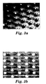
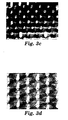
- Figures 3a-3d are magnified views of the textured side with the image of Example 1 and Comparative Example 1 from either a top-down perspective (3a and 3b) or an angled-viewing perspective (3c and 3d). As seen, little ink appears on the protrusions of Example 1 (3b and 3d). In addition, distinct droplets of ink appear on the area between protrusions.
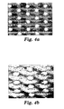
- Figures 4a-4d show the magnified views of the textured side with the image of Example 1 (4a and 4b) and Comparative Example 1 (4c and 4d) before and after the test was performed. As seen, more ink remains (after the Abrasion Test) on the image with Example 1 (4b) than with Comparative Example 1 (4d). The same ink used on the textured side was applied to the smooth polymer side of Example 1 and evaluated with the Tape Snap Test. The ink adhesion by this test was a failure because nearly all of the ink was removed.
- This example illustrates the image durability with a different polymer.
- Example 2 and Comparative Example 2 were made as Example 1 and Comparative Example 1, respectively, except the polymer was KRATON TM D1117.
- the durability of the images of Example 2 and Comparative Example 2 was evaluated with the Abrasion Test.
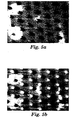
- Figures 5a-5d show the magnified views of the textured side having an image of Example 2 (5b and 5d) and Comparative Example 2 (5a and 5c) before and after the test was performed. As seen, more ink remains on the textured surface of the image in Example 2 (5d) than Comparative Example 2 (5c). Also, dots of ink were visible with both Example 2 and Comparative Example 2.
- This example illustrates the image quality of the invention with a different polymer and ink.
- Example 3 was made as Example 1 except the polymer was Polypropylene 3115 and the ink was UV-curable.
- Figure 6 shows the imaged surface of Example 3. As seen the image quality is excellent and comparable to that seen in Figure 2 for Example 1.
- This example illustrates the effect of protrusion density on an imaged surface made with the invention.
- Example 4 was made as Example 1 except the polymer was ESTANE TM 58238 and the protrusions were made with Molding Portion B resulting in a protrusion density of 390 protrusion/cm 2 (3000 protrusion/in 2 ).
- Figure 7 shows the imaged surface of Example 4. As seen the image quality is excellent and comparable to that seen in Figure 2 for Example 1. In either case (different protrusion densities), a good image resulted.
Landscapes
- Engineering & Computer Science (AREA)
- Mechanical Engineering (AREA)
- Ink Jet Recording Methods And Recording Media Thereof (AREA)
- Manufacture Of Macromolecular Shaped Articles (AREA)
- Printing Methods (AREA)
- Treatments Of Macromolecular Shaped Articles (AREA)
- Ink Jet (AREA)
- Shaping Of Tube Ends By Bending Or Straightening (AREA)
Applications Claiming Priority (3)
| Application Number | Priority Date | Filing Date | Title |
|---|---|---|---|
| US10/028,617 US6676869B2 (en) | 2001-12-21 | 2001-12-21 | Continuous process for indirect printing of polymeric films having texture |
| US28617 | 2001-12-21 | ||
| PCT/US2002/035345 WO2003057445A1 (en) | 2001-12-21 | 2002-11-04 | Continuous process for indirect printing of polymeric films having texture |
Publications (2)
| Publication Number | Publication Date |
|---|---|
| EP1455996A1 EP1455996A1 (en) | 2004-09-15 |
| EP1455996B1 true EP1455996B1 (en) | 2007-08-22 |
Family
ID=21844448
Family Applications (1)
| Application Number | Title | Priority Date | Filing Date |
|---|---|---|---|
| EP02786650A Expired - Lifetime EP1455996B1 (en) | 2001-12-21 | 2002-11-04 | Continuous process for indirect printing of polymeric films having texture |
Country Status (8)
| Country | Link |
|---|---|
| US (1) | US6676869B2 (enExample) |
| EP (1) | EP1455996B1 (enExample) |
| JP (1) | JP2005514229A (enExample) |
| KR (1) | KR100903232B1 (enExample) |
| AT (1) | ATE370827T1 (enExample) |
| AU (1) | AU2002350122A1 (enExample) |
| DE (1) | DE60222018T2 (enExample) |
| WO (1) | WO2003057445A1 (enExample) |
Families Citing this family (10)
| Publication number | Priority date | Publication date | Assignee | Title |
|---|---|---|---|---|
| GB0417634D0 (en) * | 2004-08-09 | 2004-09-08 | Structural Polymer Systems Ltd | Mould |
| FR2879948B1 (fr) | 2004-12-23 | 2007-03-23 | Inst Francais Du Petrole | Dispositif et procede de realisation de surfaces structurees dans des conduites en vue de reduire la trainee aerodynamique |
| US20090035507A1 (en) * | 2007-08-01 | 2009-02-05 | Velcro Industries B.V. | Touch Fasteners With Images |
| DE102009003683B4 (de) * | 2009-03-26 | 2011-03-24 | Hydro Aluminium Deutschland Gmbh | Verfahren zur Herstellung eines beschichteten Aluminiumbandes, Aluminiumband und dessen Verwendung |
| FR2950561B1 (fr) * | 2009-09-30 | 2011-10-28 | Ds Smith Kaysersberg | Plaque en materiau thermoplastique avec proprietes optiques ameliorees procede de fabrication d'une telle plaque et son utilisation |
| ITBO20110484A1 (it) * | 2011-08-03 | 2013-02-04 | Magis S P A | Materiale multistrato e procedimento per la realizzazione di un materiale multistrato |
| EP4119529B1 (en) * | 2012-08-20 | 2025-06-11 | CoteX Technologies Inc. | Manufacturing polymer coated controlled release fertilizers |
| EP2724864B1 (de) * | 2012-10-24 | 2018-12-26 | Heidelberger Druckmaschinen AG | Verfahren und Vorrichtung zur Erzeugung und Übertragung diffraktiver Mikrostrukturen auf einen Bedruckstoff |
| ES2551661B1 (es) * | 2014-05-20 | 2016-09-14 | Bsh Electrodomésticos España, S.A. | Método para producir un componente de aparato doméstico con un recubrimiento de color de tinta, y componente de aparato doméstico |
| US11591276B2 (en) | 2018-09-09 | 2023-02-28 | Cotex Technologies Inc. | System and method for manufacturing polymer coated controlled release fertilizers |
Family Cites Families (23)
| Publication number | Priority date | Publication date | Assignee | Title |
|---|---|---|---|---|
| US3236712A (en) * | 1962-03-28 | 1966-02-22 | American Biltrite Rubber Co | Process of producing molded and printed surface pattern in plastic stock |
| US4775310A (en) | 1984-04-16 | 1988-10-04 | Velcro Industries B.V. | Apparatus for making a separable fastener |
| US4959265A (en) | 1989-04-17 | 1990-09-25 | Minnesota Mining And Manufacturing Company | Pressure-sensitive adhesive tape fastener for releasably attaching an object to a fabric |
| US5845375A (en) | 1990-09-21 | 1998-12-08 | Minnesota Mining And Manufacturing Company | Mushroom-type hook strip for a mechanical fastener |
| US5077870A (en) | 1990-09-21 | 1992-01-07 | Minnesota Mining And Manufacturing Company | Mushroom-type hook strip for a mechanical fastener |
| JP2778331B2 (ja) * | 1992-01-29 | 1998-07-23 | 富士ゼロックス株式会社 | インクジェット記録装置 |
| US5271765A (en) | 1992-02-03 | 1993-12-21 | E. I. Du Pont De Nemours And Company | Aqueous cationic dye-based ink jet inks |
| US5707472A (en) * | 1992-10-06 | 1998-01-13 | Decora Incorporated | Composite for in-mold transfer printing and process for in-mold printing of molded plastic or rubber articles therewith |
| WO1994029070A1 (en) | 1993-06-11 | 1994-12-22 | Minnesota Mining And Manufacturing Company | Laser machined replication tooling |
| JPH08216250A (ja) | 1995-02-16 | 1996-08-27 | Kasamatsu Kako Kenkyusho:Kk | 玉虫色のプラスチックシートを製造する方法および装置 |
| US5558740A (en) * | 1995-05-19 | 1996-09-24 | Reflexite Corporation | Method and apparatus for producing seamless retroreflective sheeting |
| US6130777A (en) * | 1996-05-16 | 2000-10-10 | Dai Nippon Printing Co., Ltd. | Lenticular lens sheet with both a base sheet having lenticular elements and a surface diffusing part having elements of elementary shape smaller than lenticular elements |
| JP3312850B2 (ja) * | 1996-08-19 | 2002-08-12 | 有限会社トーワ | 合成樹脂多色着色レース模様地の製造方法 |
| ATE215439T1 (de) * | 1996-10-14 | 2002-04-15 | Idemitsu Petrochemical Co | Verfahren zur herstellung einer dekorfolie und vorrichtung zu seiner herstellung |
| DE19646318A1 (de) | 1996-11-09 | 1998-05-14 | Binder Gottlieb Gmbh & Co | Rationelles Verfahren zur Herstellung eines Haftverschlußteils aus thermoplatischem Kunststoff |
| JPH10146940A (ja) | 1996-11-15 | 1998-06-02 | Aica Kogyo Co Ltd | 化粧シートの製造方法 |
| US6120636A (en) * | 1998-01-26 | 2000-09-19 | Reflexite Corporation | Apparatus and method for producing retroreflective material having printed patterns thereon |
| US6372323B1 (en) | 1998-10-05 | 2002-04-16 | 3M Innovative Properties Company | Slip control article for wet and dry applications |
| US6190594B1 (en) | 1999-03-01 | 2001-02-20 | 3M Innovative Properties Company | Tooling for articles with structured surfaces |
| WO2000073082A1 (en) | 1999-06-01 | 2000-12-07 | 3M Innovative Properties Company | Random microembossed receptor media |
| DE60004228T2 (de) | 1999-06-01 | 2004-04-22 | 3M Innovative Properties Co., St. Paul | Optisch transparente mikrogeprägte empfangsmedien |
| US6472028B1 (en) * | 1999-08-12 | 2002-10-29 | Joseph Frazzitta | Method of producing a high gloss coating on a printed surface |
| ATE304453T1 (de) | 2000-02-08 | 2005-09-15 | 3M Innovative Properties Co | Verbesserte verfahren für kalten bildtransfer |
-
2001
- 2001-12-21 US US10/028,617 patent/US6676869B2/en not_active Expired - Fee Related
-
2002
- 2002-11-04 KR KR1020047009602A patent/KR100903232B1/ko not_active Expired - Fee Related
- 2002-11-04 DE DE60222018T patent/DE60222018T2/de not_active Expired - Lifetime
- 2002-11-04 AU AU2002350122A patent/AU2002350122A1/en not_active Abandoned
- 2002-11-04 JP JP2003557786A patent/JP2005514229A/ja active Pending
- 2002-11-04 WO PCT/US2002/035345 patent/WO2003057445A1/en not_active Ceased
- 2002-11-04 EP EP02786650A patent/EP1455996B1/en not_active Expired - Lifetime
- 2002-11-04 AT AT02786650T patent/ATE370827T1/de not_active IP Right Cessation
Non-Patent Citations (1)
| Title |
|---|
| None * |
Also Published As
| Publication number | Publication date |
|---|---|
| US20030118783A1 (en) | 2003-06-26 |
| DE60222018D1 (de) | 2007-10-04 |
| US6676869B2 (en) | 2004-01-13 |
| KR20040068288A (ko) | 2004-07-30 |
| KR100903232B1 (ko) | 2009-06-17 |
| JP2005514229A (ja) | 2005-05-19 |
| WO2003057445A1 (en) | 2003-07-17 |
| AU2002350122A1 (en) | 2003-07-24 |
| DE60222018T2 (de) | 2008-05-15 |
| EP1455996A1 (en) | 2004-09-15 |
| ATE370827T1 (de) | 2007-09-15 |
Similar Documents
| Publication | Publication Date | Title |
|---|---|---|
| US6386699B1 (en) | Embossed receptor media | |
| EP1028639B1 (en) | Coextruded mechanical fastener constructions | |
| US6649249B1 (en) | Random microembossed receptor media | |
| EP1263605B1 (en) | Improved methods for cold image transfer | |
| CN100341714C (zh) | 墨水受体介质 | |
| CN1170693C (zh) | 喷墨接受介质及其制法、成象喷墨接受介质、图象的制法 | |
| EP1455996B1 (en) | Continuous process for indirect printing of polymeric films having texture | |
| EP2578412B1 (en) | Printable film | |
| JP3925979B2 (ja) | ホットメルト型インクジェット記録用紙 | |
| MXPA00003156A (en) | Coextruded mechanical fastener constructions |
Legal Events
| Date | Code | Title | Description |
|---|---|---|---|
| PUAI | Public reference made under article 153(3) epc to a published international application that has entered the european phase |
Free format text: ORIGINAL CODE: 0009012 |
|
| 17P | Request for examination filed |
Effective date: 20040513 |
|
| AK | Designated contracting states |
Kind code of ref document: A1 Designated state(s): AT BE BG CH CY CZ DE DK EE ES FI FR GB GR IE IT LI LU MC NL PT SE SK TR |
|
| AX | Request for extension of the european patent |
Extension state: AL LT LV MK RO SI |
|
| GRAP | Despatch of communication of intention to grant a patent |
Free format text: ORIGINAL CODE: EPIDOSNIGR1 |
|
| GRAS | Grant fee paid |
Free format text: ORIGINAL CODE: EPIDOSNIGR3 |
|
| GRAA | (expected) grant |
Free format text: ORIGINAL CODE: 0009210 |
|
| AK | Designated contracting states |
Kind code of ref document: B1 Designated state(s): AT BE BG CH CY CZ DE DK EE ES FI FR GB GR IE IT LI LU MC NL PT SE SK TR |
|
| REG | Reference to a national code |
Ref country code: GB Ref legal event code: FG4D |
|
| REG | Reference to a national code |
Ref country code: CH Ref legal event code: EP |
|
| REG | Reference to a national code |
Ref country code: IE Ref legal event code: FG4D |
|
| REF | Corresponds to: |
Ref document number: 60222018 Country of ref document: DE Date of ref document: 20071004 Kind code of ref document: P |
|
| PG25 | Lapsed in a contracting state [announced via postgrant information from national office to epo] |
Ref country code: FI Free format text: LAPSE BECAUSE OF FAILURE TO SUBMIT A TRANSLATION OF THE DESCRIPTION OR TO PAY THE FEE WITHIN THE PRESCRIBED TIME-LIMIT Effective date: 20070822 Ref country code: NL Free format text: LAPSE BECAUSE OF FAILURE TO SUBMIT A TRANSLATION OF THE DESCRIPTION OR TO PAY THE FEE WITHIN THE PRESCRIBED TIME-LIMIT Effective date: 20070822 Ref country code: BG Free format text: LAPSE BECAUSE OF FAILURE TO SUBMIT A TRANSLATION OF THE DESCRIPTION OR TO PAY THE FEE WITHIN THE PRESCRIBED TIME-LIMIT Effective date: 20071122 Ref country code: ES Free format text: LAPSE BECAUSE OF FAILURE TO SUBMIT A TRANSLATION OF THE DESCRIPTION OR TO PAY THE FEE WITHIN THE PRESCRIBED TIME-LIMIT Effective date: 20071203 |
|
| NLV1 | Nl: lapsed or annulled due to failure to fulfill the requirements of art. 29p and 29m of the patents act | ||
| PG25 | Lapsed in a contracting state [announced via postgrant information from national office to epo] |
Ref country code: LI Free format text: LAPSE BECAUSE OF FAILURE TO SUBMIT A TRANSLATION OF THE DESCRIPTION OR TO PAY THE FEE WITHIN THE PRESCRIBED TIME-LIMIT Effective date: 20070822 Ref country code: CH Free format text: LAPSE BECAUSE OF FAILURE TO SUBMIT A TRANSLATION OF THE DESCRIPTION OR TO PAY THE FEE WITHIN THE PRESCRIBED TIME-LIMIT Effective date: 20070822 Ref country code: AT Free format text: LAPSE BECAUSE OF FAILURE TO SUBMIT A TRANSLATION OF THE DESCRIPTION OR TO PAY THE FEE WITHIN THE PRESCRIBED TIME-LIMIT Effective date: 20070822 |
|
| REG | Reference to a national code |
Ref country code: CH Ref legal event code: PL |
|
| PG25 | Lapsed in a contracting state [announced via postgrant information from national office to epo] |
Ref country code: BE Free format text: LAPSE BECAUSE OF FAILURE TO SUBMIT A TRANSLATION OF THE DESCRIPTION OR TO PAY THE FEE WITHIN THE PRESCRIBED TIME-LIMIT Effective date: 20070822 |
|
| EN | Fr: translation not filed | ||
| PG25 | Lapsed in a contracting state [announced via postgrant information from national office to epo] |
Ref country code: DK Free format text: LAPSE BECAUSE OF FAILURE TO SUBMIT A TRANSLATION OF THE DESCRIPTION OR TO PAY THE FEE WITHIN THE PRESCRIBED TIME-LIMIT Effective date: 20070822 Ref country code: GR Free format text: LAPSE BECAUSE OF FAILURE TO SUBMIT A TRANSLATION OF THE DESCRIPTION OR TO PAY THE FEE WITHIN THE PRESCRIBED TIME-LIMIT Effective date: 20071123 |
|
| PGFP | Annual fee paid to national office [announced via postgrant information from national office to epo] |
Ref country code: GB Payment date: 20071128 Year of fee payment: 6 |
|
| PG25 | Lapsed in a contracting state [announced via postgrant information from national office to epo] |
Ref country code: PT Free format text: LAPSE BECAUSE OF FAILURE TO SUBMIT A TRANSLATION OF THE DESCRIPTION OR TO PAY THE FEE WITHIN THE PRESCRIBED TIME-LIMIT Effective date: 20080122 Ref country code: CZ Free format text: LAPSE BECAUSE OF FAILURE TO SUBMIT A TRANSLATION OF THE DESCRIPTION OR TO PAY THE FEE WITHIN THE PRESCRIBED TIME-LIMIT Effective date: 20070822 Ref country code: SK Free format text: LAPSE BECAUSE OF FAILURE TO SUBMIT A TRANSLATION OF THE DESCRIPTION OR TO PAY THE FEE WITHIN THE PRESCRIBED TIME-LIMIT Effective date: 20070822 |
|
| PLBE | No opposition filed within time limit |
Free format text: ORIGINAL CODE: 0009261 |
|
| STAA | Information on the status of an ep patent application or granted ep patent |
Free format text: STATUS: NO OPPOSITION FILED WITHIN TIME LIMIT |
|
| PG25 | Lapsed in a contracting state [announced via postgrant information from national office to epo] |
Ref country code: MC Free format text: LAPSE BECAUSE OF NON-PAYMENT OF DUE FEES Effective date: 20071130 Ref country code: SE Free format text: LAPSE BECAUSE OF FAILURE TO SUBMIT A TRANSLATION OF THE DESCRIPTION OR TO PAY THE FEE WITHIN THE PRESCRIBED TIME-LIMIT Effective date: 20071122 |
|
| 26N | No opposition filed |
Effective date: 20080526 |
|
| PG25 | Lapsed in a contracting state [announced via postgrant information from national office to epo] |
Ref country code: IE Free format text: LAPSE BECAUSE OF NON-PAYMENT OF DUE FEES Effective date: 20071105 |
|
| PG25 | Lapsed in a contracting state [announced via postgrant information from national office to epo] |
Ref country code: EE Free format text: LAPSE BECAUSE OF FAILURE TO SUBMIT A TRANSLATION OF THE DESCRIPTION OR TO PAY THE FEE WITHIN THE PRESCRIBED TIME-LIMIT Effective date: 20070822 |
|
| PG25 | Lapsed in a contracting state [announced via postgrant information from national office to epo] |
Ref country code: FR Free format text: LAPSE BECAUSE OF NON-PAYMENT OF DUE FEES Effective date: 20071130 |
|
| GBPC | Gb: european patent ceased through non-payment of renewal fee |
Effective date: 20081104 |
|
| PG25 | Lapsed in a contracting state [announced via postgrant information from national office to epo] |
Ref country code: CY Free format text: LAPSE BECAUSE OF FAILURE TO SUBMIT A TRANSLATION OF THE DESCRIPTION OR TO PAY THE FEE WITHIN THE PRESCRIBED TIME-LIMIT Effective date: 20070822 |
|
| PG25 | Lapsed in a contracting state [announced via postgrant information from national office to epo] |
Ref country code: LU Free format text: LAPSE BECAUSE OF NON-PAYMENT OF DUE FEES Effective date: 20071104 |
|
| PG25 | Lapsed in a contracting state [announced via postgrant information from national office to epo] |
Ref country code: TR Free format text: LAPSE BECAUSE OF FAILURE TO SUBMIT A TRANSLATION OF THE DESCRIPTION OR TO PAY THE FEE WITHIN THE PRESCRIBED TIME-LIMIT Effective date: 20070822 |
|
| PG25 | Lapsed in a contracting state [announced via postgrant information from national office to epo] |
Ref country code: GB Free format text: LAPSE BECAUSE OF NON-PAYMENT OF DUE FEES Effective date: 20081104 |
|
| PG25 | Lapsed in a contracting state [announced via postgrant information from national office to epo] |
Ref country code: IT Free format text: LAPSE BECAUSE OF NON-PAYMENT OF DUE FEES Effective date: 20071130 |
|
| PGFP | Annual fee paid to national office [announced via postgrant information from national office to epo] |
Ref country code: DE Payment date: 20101027 Year of fee payment: 9 |
|
| REG | Reference to a national code |
Ref country code: DE Ref legal event code: R119 Ref document number: 60222018 Country of ref document: DE Effective date: 20120601 |
|
| PG25 | Lapsed in a contracting state [announced via postgrant information from national office to epo] |
Ref country code: DE Free format text: LAPSE BECAUSE OF NON-PAYMENT OF DUE FEES Effective date: 20120601 |