EP1455144A1 - Lüftungsgitter - Google Patents
Lüftungsgitter Download PDFInfo
- Publication number
- EP1455144A1 EP1455144A1 EP04003569A EP04003569A EP1455144A1 EP 1455144 A1 EP1455144 A1 EP 1455144A1 EP 04003569 A EP04003569 A EP 04003569A EP 04003569 A EP04003569 A EP 04003569A EP 1455144 A1 EP1455144 A1 EP 1455144A1
- Authority
- EP
- European Patent Office
- Prior art keywords
- ventilation grille
- grille according
- perforated
- air
- ventilation
- Prior art date
- Legal status (The legal status is an assumption and is not a legal conclusion. Google has not performed a legal analysis and makes no representation as to the accuracy of the status listed.)
- Granted
Links
Images

Classifications
-
- F—MECHANICAL ENGINEERING; LIGHTING; HEATING; WEAPONS; BLASTING
- F24—HEATING; RANGES; VENTILATING
- F24F—AIR-CONDITIONING; AIR-HUMIDIFICATION; VENTILATION; USE OF AIR CURRENTS FOR SCREENING
- F24F13/00—Details common to, or for air-conditioning, air-humidification, ventilation or use of air currents for screening
- F24F13/08—Air-flow control members, e.g. louvres, grilles, flaps or guide plates
- F24F13/082—Grilles, registers or guards
-
- E—FIXED CONSTRUCTIONS
- E04—BUILDING
- E04F—FINISHING WORK ON BUILDINGS, e.g. STAIRS, FLOORS
- E04F17/00—Vertical ducts; Channels, e.g. for drainage
- E04F17/04—Air-ducts or air channels
Definitions
- the invention relates to a ventilation grille, preferably on transformer and switchgear, Air conditioning and filter systems as well as vehicle systems to be ventilated, which in the External walls of a housing, building, an enclosure or the like can be arranged.
- Ventilation grilles are known. In this case, for example, folding grilles are also used various applications and users for years. It is still known, a perforated plate with specially arranged openings through pressing from folds to form a lamellar grid. Here are water-repellent Surfaces provided that have no perforations and air-permeable Areas with perforations. The air-permeable areas are in the water-protected Areas provided. Depending on the application, the breathable Areas with regard to the open cross-section are changed. These well-known Ventilation grilles have various disadvantages that affect the area of application limit significantly.
- the object of the invention is to provide a ventilation grille that is easy and reasonable cost to manufacture and at the same time the previously described disadvantages of known solutions are eliminated.
- the invention is based on the prior art described above and proposes a ventilation grille to solve the task, preferably on transformer and switchgear, air conditioning and filter systems as well as vehicle systems to be ventilated, before that in the outer walls of an enclosure, building, an enclosure or the like can be arranged or used, formed from one to one Lamellar lattice pressed perforated plate, in particular a folded perforated plate, with at least one air-permeable area, which is characterized by that a double-shell design of the grid area is provided and at least two fold perforated sheets viewed in cross section one behind the other, in particular spaced from one another, forming a common element are.
- the double-shell design also makes a number of special ones Advantages over the solutions known from the prior art achieved. This is what is required for ventilation grilles, especially in the area of electrical systems Punch safety achieved, because of the double-shell design, the poking is no longer possible.
- the wire or pointed object is at the Puncture the front shell for an obstacle, namely the second shell hit, so that a further puncture is not possible.
- the wire, object or the like is between the two shells up, down or distracted to the side. This is a puncture of the inner or rear Shell or the rear perforated plate is no longer possible.
- the double-shell training also forms a much better one Protection against rain, driving rain, snow or rain.
- the moisture can initially run off on the outer shell. Possibly However, entering water or moisture can both on the Inside of the outer shell as well as on the inside and outside of the inner shell run down easily and through arranged in the lower area Drainage openings can be derived, for example.
- Drainage openings can be derived, for example.
- the double-shell design of the ventilation grille only low amounts of moisture between the two shells, they can Moisture droplets adhere to the grid material due to the adhesion and after drain or evaporate below.
- This positive and desired property works even in the event of condensation, caused by temperature fluctuations, as they occur naturally, or by turning on and off temperature fluctuations occurring in the systems. For example, it can condensation can form after a transformer station has been switched off for a long time, when it is put back into operation. The transformer or transformers will be there warms up faster than the casing, building or housing.
- Incoming dust settles between the two shells of the grille and falls down due to gravity. There he can, together with possibly to be derived Moisture is discharged to the outside via the drainage facilities become. This prevents dust from entering the interior of the housing, building or the like is significantly reduced, so that the cleaning cycles are extended be or can be omitted entirely.
- Ventilation grilles in electrical systems for example in transformer stations also have a high stability in order to avoid malfunctions or accidents absorb high pressures without being destroyed.
- a double-shell education is an advantage because it is better able to handle such loads intercept safely.
- the double-shell design also has the advantage that depending on the application the required proportion of air-permeable areas can be varied very easily, without compromising puncture resistance and the stability of the or the grid.
- the invention is also characterized in that that at least two corrugated perforated sheets viewed in cross section one behind the other, in particular spaced from one another, forming a common element are.
- this involves special training of the double-shell element, which consists of prefabricated perforated sheets special folding and folding can be obtained.
- This execution leads also to improve the manufacturing process for the invention Ventilation grille. This will be described in more detail later.
- the at least two corrugated perforated sheets were obtained from single folded perforated sheets and are connected to one another by connecting means.
- the connection is easier Shape by means of an appropriately selected bevel with a positive connection possible at least in the upper and lower area.
- connections possible for example gluing, welding, preferably Spot welding, screwing, soldering or the like.
- Another aspect of the invention is indicated in that the at least two corrugated perforated sheets by cutting and folding from a single element were obtained.
- This variant is particularly inexpensive to manufacture, has very good stability and high variability with regard to the possible designs. With correspondingly existing tools, the manufacture is quite not expensive.
- the area of application of the ventilation grilles produced is extreme universal.
- the material forming the corrugated perforated sheets is made of Endless or strand or plate material by cutting, cutting or the like was obtained. This is a problem with the corresponding production quantities further improve the manufacturing process.
- end-side closure plates are provided that are attached to Different sizes adjustable, designed to surround or enclose the grille are. So it is possible, for example, to determine the front closing plates Keep stock sizes in order not to be tied to specific manufacturing dimensions to be.
- a ventilation grille which is characterized in that the air-permeable area (s) is / are designed as areas provided with perforations.
- the perforations are variable in their size, shape and arrangement and quite cheap Get punching for example.
- the perforations the size or diameter of the air-permeable area (s) variable, according to the different according to the purpose in the event of faults or breakdowns, those to be expected inside the housing Pressures or gas flows are adaptable to them.
- the sheet thicknesses intended is also an adjustment in this regard by varying the sheet thicknesses intended.
- the opening or openings have a rectangular, have a square, oval, round or polygonal shape. Also the number and size of the breakthroughs depends on the respective application very universal and not limited to a few sizes and shapes.
- Another aspect of the invention is indicated in that the air-permeable Areas of the corrugated perforated plates arranged one behind the other are offset from one another are arranged. This offset increases the water or moisture repellency Properties of the ventilation grille according to the invention further. Also the This arrangement further reduces dust permeability.
- water-protected areas are provided at least on the rear or inner corrugated perforated plate. This can also be formed on the front or outer perforated sheet metal.
- the moisture that is deposited on the perforated sheets is caused by the Elasticity of the same or the adhesion to the perforated sheet metal is kept and passes along the sheets to the lower area, where it is discharged to the outside becomes.
- a feed edge at least in the lower area of the ventilation grille or in or on the frame is provided, which has outward-facing drainage openings, about the possibly entering water and / or condensation water to the outside is derived. It is advantageous if the drainage openings are designed as so-called gill openings.
- a cleaning device is provided which is preferably arranged between the two perforated sheets.
- the cleaning device is designed such that it is pneumatic, hydraulically or mechanically cleaned.
- various cleaning devices intended can, for example, as a spray device in the form of a Spray bar can be formed. This is advantageously in the upper area of the grid between the two perforated sheets. It is possible also to provide a nozzle arrangement which can be acted upon by compressed air and which has a Cleaning with compressed air enables. Scraper devices are also advantageous can be arranged between the perforated sheets. Also with cleaning brushes provided cleaning devices are according to the invention between the corrugated perforated sheets to arrange movable.
- a further development of the ventilation grille according to the invention is characterized by this from that an insect protection or protection against small organisms penetrating into the interior is provided on or in the grid.
- the insect protection or protection against small organisms penetrating into the interior is according to a development of the invention by the choice of size the perforations, at least the rear perforated plate guaranteed.
- the invention also provides a system of ventilation grilles or for the production of Ventilation grilles of different sizes, especially after one or more of the training courses described above, consisting of endless or strand material for corrugated perforated sheets with different sizes of air-permeable Areas and breakthroughs, face plates as Continuous or strand material or prefabricated for certain sizes, insect protection devices or protective devices to prevent intrusion of small organisms and various cleaning devices. That is it the manufacturer or supplier of the ventilation grille possible, all system components to produce or keep in stock to order certain sizes quickly assemble them according to the requirements and to deliver
- the invention also relates to a transformer or switchgear, air conditioning or filter system as well as vehicle system to be ventilated with a ventilation grille after one or several of the training courses described above.
- the method according to the invention is of course also with sheet material for Perforated perforated sheets available as single sheets.
- the plates are cut to the appropriate dimensions, folded and then placed on top of one another and with connecting means, e.g. Spot welding, so connected that the two plates are spaced apart and the air-permeable areas are offset from one another.
- connecting means e.g. Spot welding
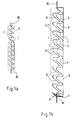
- FIG. 1 a, 1b and 1 c each show a section through different embodiments of the ventilation grille according to the invention.
- the front or outer corrugated perforated sheet is designated
- the reference number 2 affects the rear or inner perforated sheet.
- the two corrugated perforated sheets 1 and 2 are by means of connecting means 10, in the exemplary embodiment with spot welding connections connected.
- the ventilation grille is surrounded by a frame 8.
- Air-permeable areas 4 are arranged in the front perforated sheet 1. Some of these air-permeable areas can be designed as an opening 5. All air-permeable areas of the front corrugated perforated plate 1 can also be used be designed as an opening 5.
- the Figures 1a and 1b differ only in the different Formation of the feed edge 6.
- the folds are preferably designed as V-lamellae, as these can withstand the explosion pressure or resist particularly effectively an implosion pressure. This is possible, for example also in that the lamellae are compressed by the pressure that occurs are, but thereby represent a greater resistance.
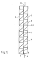
- FIG. 2 shows a front view of the ventilation grille according to the invention.
- the Representation is cut on one side, so that both the front perforated sheet 1, as well as the rear perforated sheet 2 are visible.
- the already based the reference numerals described in FIG. 1 were used identically in FIG. 2, so that there is no renewed performance.
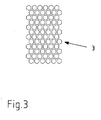
- FIG. 3 shows a detailed view of an air-permeable area with perforations, which are designed as a hexagon.
- the size of the perforations is so chosen so that insects cannot pass through them. Also the size of the perforations depending on the expected explosion pressure inside the system when an accident occurs.
Landscapes
- Engineering & Computer Science (AREA)
- Architecture (AREA)
- Chemical & Material Sciences (AREA)
- Combustion & Propulsion (AREA)
- Mechanical Engineering (AREA)
- General Engineering & Computer Science (AREA)
- Civil Engineering (AREA)
- Structural Engineering (AREA)
- Air-Flow Control Members (AREA)
- Specific Sealing Or Ventilating Devices For Doors And Windows (AREA)
- Liquid Carbonaceous Fuels (AREA)
- Storage Of Fruits Or Vegetables (AREA)
Abstract
Description
- Ablängen bzw. Ausschneiden des die Faltenlochbleche bildende Materials aus Endlos-, Strang- oder Plattenmaterialmaterial, vorzugsweise einteilig ausgebildetes Strang- oder Plattenmatereial,
- Abkanten der Faltenlochbleche in die gewünschte Form,
- Verbinden der Faltenlochbleche durch Verbindungsmittel,
- Zuschneiden und Befestigen der den Rahmen bildenden Außenseiten.
- Fig. 1a, 1b und 1c
- Schnitt durch Ausführungsformen des erfindungsgemäßen Lüftungsgitters
- Fig. 2
- Eine Vorderansicht der Darstellung gem. Fig.1
- Fig. 3
- Detailansicht eines luftdurchlässigen Bereiches mit sechseckiger Form
Claims (23)
- Lüftungsgitter, vorzugsweise an Trafo- und Schaltanlagen, Klima- und Filteranlagen sowie zu belüftenden Fahrzeuganlagen, das in den Außenwänden eines Gehäuses, Gebäudes, einer Umhüllung oder dergleichen anordenbar ist, gebildet aus einem zu einem Lamellengitter gepressten Lochblech, insbesondere einem Faltenlochblech, und mindestens einem luftdurchlässigen Bereich, dadurch gekennzeichnet, dass eine doppelschaligen Ausbildung des Gitterbereiches vorgesehen ist und mindestens zwei Faltenlochbleche (1, 2) im Querschnitt betrachtet hintereinander, insbesondere beabstandet voneinander, ein gemeinsames Element bildend angeordnet sind.
- Lüftungsgitter nach Anspruch 1, dadurch gekennzeichnet, dass der oder die luftdurchlässige(n) Bereich(e) (3, 4) als mit Lochungen versehene(r) Bereich(e) ausgebildet ist / sind.
- Lüftungsgitter nach einem oder beiden der vorstehenden Ansprüche, dadurch gekennzeichnet, dass die Lochungen der oder des luftdurchlässige(n) Bereich(e)s (3, 4) in ihrer Größe bzw. im Durchmesser variierbar, entsprechend der verschiedenen gemäß des Einsatzzweckes bei Störungen bzw. Havarien zu erwartenden im Inneren des Gehäuses auftretenden Drücke bzw. Gasströme an diese anpassbar, ausgebildet sind.
- Lüftungsgitter nach einem oder mehreren der vorstehenden Ansprüche, dadurch gekennzeichnet, dass die mindestens zwei Faltenlochbleche (1, 2) aus Einzelfaltenlochblechen gebildet sind, die durch Verbinden mit Verbindungsmitteln (10) bzw. Verbindungsverfahren erhalten wurden.
- Lüftungsgitter nach einem oder beiden der vorstehenden Ansprüche, dadurch gekennzeichnet, dass die mindestens zwei Faltenlochbleche (1, 2) durch Ablängen und Abkanten aus einem einzelnen Element erhalten wurden.
- Lüftungsgitter nach einem oder mehreren der vorstehenden Ansprüche, dadurch gekennzeichnet, dass das die Faltenlochbleche (1, 2) bildende Material aus Endlos- bzw. Strang- oder Plattenmaterial durch Ablängen, Ausschneiden oder dergleichen erhalten wurde.
- Lüftungsgitter nach einem oder mehreren der vorstehenden Ansprüche, dadurch gekennzeichnet, dass stirnseitige Verschlussbleche vorgesehen sind, die an verschiedene Größen anpassbar, zur Ein- bzw. Umfassung des Gitters ausgebildet sind.
- Lüftungsgitter nach einem oder mehreren der vorstehenden Ansprüche, dadurch gekennzeichnet, dass ein Teil der luftdurchlässigen Bereiche (3, 4) als Durchbruch (5) ausgebildet ist.
- Lüftungsgitter nach einem oder mehreren der vorstehenden Ansprüche, dadurch gekennzeichnet, dass zumindest ein Teil der luftdurchlässigen Bereiche (3, 4) des vorderen bzw. äußeren Faltenlochbleches (1) als Durchbruch (5) ausgebildet ist.
- Lüftungsgitter nach einem oder mehreren der vorstehenden Ansprüche, dadurch gekennzeichnet, dass der Durchbruch oder die Durchbrüche (5) eine rechteckige, quadratische, ovale, runde oder mehreckige Form aufweisen.
- Lüftungsgitter nach einem oder mehreren der vorstehenden Ansprüche, dadurch gekennzeichnet, dass die luftdurchlässigen Bereiche (3, 4) der hintereinander angeordneten Faltenlochbleche (1, 2) versetzt zueinander angeordnet sind.
- Lüftungsgitter nach einem oder mehreren der vorstehenden Ansprüche, dadurch gekennzeichnet, dass die luftdurchlässigen Bereiche (3, 4) und/ oder Durchbrüche (5) der hintereinanderliegenden Faltenlochbleche (1, 2) derart versetzt angeordnet sind, dass die Durchbrüche (5) des vorderen Faltenlochbleches (1) von dem hinteren Faltenlochblech (2) verdeckt sind.
- Lüftungsgitter nach einem oder mehreren der vorstehenden Ansprüche, dadurch gekennzeichnet, dass die hintereinanderliegenden Faltenlochbleche (1, 2) derart versetzt zueinander und beabstandet voneinander angeordnet sind, dass ein Durchstochern nicht ermöglicht ist.
- Lüftungsgitter nach einem oder mehreren der vorstehenden Ansprüche, dadurch gekennzeichnet, dass wassergeschützte Bereiche (9), zumindest am hinteren bzw. inneren Faltenlochblech (2) vorgesehen sind.
- Lüftungsgitter nach einem oder mehreren der vorstehenden Ansprüche, dadurch gekennzeichnet, dass wassergeschützte Bereiche (9) und luftdurchlässige Bereiche (3, 4) versetzt zueinander angeordnet sind, derart dass eventuell eintretende oder sich niederschlagende Feuchtigkeit vorzugsweise an den wassergeschützten Bereichen senkrecht in Einbaurichtung nach unten abläuft.
- Lüftungsgitter nach einem oder mehreren der vorstehenden Ansprüche, dadurch gekennzeichnet, dass eine Zuführkantung (6) zumindest im unteren Bereich des Lüftungsgitters bzw. im oder am Rahmen (8) vorgesehen ist, welche nach außen weisende Entwässerungsöffnungen (7) aufweist, über die eventuell eintretende Flüssigkeiten, wie z.B. Wasser und / oder Schwitzwasser nach außen abgeleitet wird.
- Lüftungsgitter nach einem oder mehreren der vorstehenden Ansprüche, dadurch gekennzeichnet, dass eine Reinigungsvorrichtung vorgesehen ist, die vorzugsweise zwischen den beiden Faltenlochblechen (1, 2) angeordnet ist.
- Lüftungsgitter nach einem oder mehreren der vorstehenden Ansprüche, dadurch gekennzeichnet, dass die Reinigungsvorrichtung derart ausgebildet ist, dass sie pneumatisch, hydraulisch oder mechanisch reinigt.
- Lüftungsgitter nach einem oder mehreren der vorstehenden Ansprüche, dadurch gekennzeichnet, dass ein Insektenschutz bzw. Schutz vor in das Innere eindringenden Kleinlebewesen an oder in dem Gitter vorgesehen ist.
- Lüftungsgitter nach einem oder mehreren der vorstehenden Ansprüche, dadurch gekennzeichnet, dass der Insektenschutz bzw. Schutz vor in das Innere eindringenden Kleinlebewesen durch die Wahl der Größe der Lochungen, zumindest des hinteren Faltenlochbleches (2) gewährleistet ist.
- System von Lüftungsgittern bzw. zur Anfertigung von Lüftungsgittern unterschiedlicher Größe, insbesondere nach einem oder mehreren der vorstehenden Ansprüche 1 bis 20, bestehend aus Endlos- bzw. Strangmaterial oder vorgefertigt in verschiedenen Abmessungen für Faltenlochbleche (1, 2) mit unterschiedlichen Größen der luftdurchlässigen Bereiche (3, 4) und Durchbrüche (5), stirnseitigen Verschlussblechen als Endlos- oder Strangmaterial oder für bestimmte Größen vorgefertigt, Insektenschutzvorrichtungen bzw. Schutzvorrichtungen zur Verhinderung des Eindringens von Kleinlebewesen und verschiedenen Reinigungsvorrichtungen.
- Trafo- oder Schaltanlage, Klima- oder Filteranlage sowie zu belüftende Fahrzeuganlage mit einem Lüftungsgitter nach einem oder mehreren der vorhergehenden Ansprüche 1 bis 20.
- Verfahren zur Herstellung eines Lüftungsgitters, insbesondere zur Herstellung eines Lüftungsgitters nach einem der Ansprüche 1 bis 20, gekennzeichnet durch die Abfolge folgender Verfahrensschritte:Ablängen bzw. Ausschneiden des die Faltenlochbleche bildende Materials aus Endlos-, Strang- oder Plattenmaterialmaterial, vorzugsweise einteilig ausgebildetem Strang- oder Plattenmaterial,Abkanten der Faltenlochbleche in die gewünschte Form,Verbinden der Faltenlochbleche durch Verbindungsmittel,Zuschneiden und Befestigen der den Rahmen bildenden Außenseiten.
Applications Claiming Priority (2)
| Application Number | Priority Date | Filing Date | Title |
|---|---|---|---|
| DE20303783U DE20303783U1 (de) | 2003-03-07 | 2003-03-07 | Lüftungsgitter |
| DE20303783U | 2003-03-07 |
Publications (2)
| Publication Number | Publication Date |
|---|---|
| EP1455144A1 true EP1455144A1 (de) | 2004-09-08 |
| EP1455144B1 EP1455144B1 (de) | 2006-12-27 |
Family
ID=28799134
Family Applications (1)
| Application Number | Title | Priority Date | Filing Date |
|---|---|---|---|
| EP04003569A Expired - Lifetime EP1455144B1 (de) | 2003-03-07 | 2004-02-18 | Lüftungsgitter |
Country Status (4)
| Country | Link |
|---|---|
| EP (1) | EP1455144B1 (de) |
| AT (1) | ATE349659T1 (de) |
| DE (2) | DE20303783U1 (de) |
| PL (1) | PL365809A1 (de) |
Cited By (1)
| Publication number | Priority date | Publication date | Assignee | Title |
|---|---|---|---|---|
| CN111156633A (zh) * | 2020-02-12 | 2020-05-15 | 南通市第一人民医院 | 一种洁净用新风系统及其使用方法 |
Citations (6)
| Publication number | Priority date | Publication date | Assignee | Title |
|---|---|---|---|---|
| US3302554A (en) * | 1965-01-05 | 1967-02-07 | Leslie Welding Co Inc | One piece louver unit |
| AU453831B2 (en) * | 1971-03-23 | 1974-09-26 | Turco Industries Pty. Ltd | Improvements in and relating to ventilators |
| EP0501840A2 (de) * | 1991-03-01 | 1992-09-02 | H.H. Robertson (U.K.) Limited | Belüftende Wand |
| US5349799A (en) * | 1993-08-25 | 1994-09-27 | Mid-America Building Products Corporation | Plastic gable vent |
| DE19729015A1 (de) * | 1997-07-02 | 1999-01-07 | Karl Kern | Verkleidungsblech und Verfahren zu seier Herstellung |
| US6138424A (en) * | 1998-07-28 | 2000-10-31 | Beutler Heating & Air Conditioning | Vent apparatus for attachment to a building structure |
-
2003
- 2003-03-07 DE DE20303783U patent/DE20303783U1/de not_active Expired - Lifetime
-
2004
- 2004-02-18 EP EP04003569A patent/EP1455144B1/de not_active Expired - Lifetime
- 2004-02-18 DE DE502004002411T patent/DE502004002411D1/de not_active Expired - Fee Related
- 2004-02-18 AT AT04003569T patent/ATE349659T1/de not_active IP Right Cessation
- 2004-03-03 PL PL36580904A patent/PL365809A1/xx unknown
Patent Citations (6)
| Publication number | Priority date | Publication date | Assignee | Title |
|---|---|---|---|---|
| US3302554A (en) * | 1965-01-05 | 1967-02-07 | Leslie Welding Co Inc | One piece louver unit |
| AU453831B2 (en) * | 1971-03-23 | 1974-09-26 | Turco Industries Pty. Ltd | Improvements in and relating to ventilators |
| EP0501840A2 (de) * | 1991-03-01 | 1992-09-02 | H.H. Robertson (U.K.) Limited | Belüftende Wand |
| US5349799A (en) * | 1993-08-25 | 1994-09-27 | Mid-America Building Products Corporation | Plastic gable vent |
| DE19729015A1 (de) * | 1997-07-02 | 1999-01-07 | Karl Kern | Verkleidungsblech und Verfahren zu seier Herstellung |
| US6138424A (en) * | 1998-07-28 | 2000-10-31 | Beutler Heating & Air Conditioning | Vent apparatus for attachment to a building structure |
Cited By (2)
| Publication number | Priority date | Publication date | Assignee | Title |
|---|---|---|---|---|
| CN111156633A (zh) * | 2020-02-12 | 2020-05-15 | 南通市第一人民医院 | 一种洁净用新风系统及其使用方法 |
| CN111156633B (zh) * | 2020-02-12 | 2024-02-20 | 南通市第一人民医院 | 一种洁净用新风系统及其使用方法 |
Also Published As
| Publication number | Publication date |
|---|---|
| DE20303783U1 (de) | 2003-10-02 |
| EP1455144B1 (de) | 2006-12-27 |
| ATE349659T1 (de) | 2007-01-15 |
| DE502004002411D1 (de) | 2007-02-08 |
| PL365809A1 (en) | 2004-09-20 |
Similar Documents
| Publication | Publication Date | Title |
|---|---|---|
| EP1867375A1 (de) | Filterlüfter mit einer Schnellbefestigungseinrichtung | |
| EP2561740A1 (de) | Lamellengitter | |
| EP0386717B1 (de) | Verfahren zum Herstellen eines Lüftungsgitters | |
| DE8208932U1 (de) | Druckwellen-schutzklappe fuer kanaele von lueftungs- und/oder klimaanlagen | |
| DE202006011879U1 (de) | Gitterwandgestell | |
| DE202012002498U1 (de) | Tür, Metallkonstruktionsprofil einer Zarge oder eines Rahmens für eine Tür oder ein Fenster | |
| AT406700B (de) | Tür, insbesondere brandschutztür | |
| EP1455144B1 (de) | Lüftungsgitter | |
| DE202011106891U1 (de) | Lüftungseinsatz, insbesondere für Transformatorstationen | |
| DE102016103950B4 (de) | Anordnung zur Be- und Entlüftung von Räumen im Bereich eines Fensters | |
| WO2008135347A1 (de) | Schottvorrichtung für eine stromverteilereinheit | |
| DE3324153A1 (de) | Objektschutzgitter | |
| DE1961701C3 (de) | Wetterfestes Lufteinlaßgitter | |
| EP2982014B1 (de) | Erreichung einer schutzart für elektrische und elektronische geräte, insbesondere für schaltschränke | |
| EP2634501A1 (de) | Entlüftungsvorrichtung insbesondere für Gebäude | |
| DE102007039306B4 (de) | Luftauslass | |
| DE19912567B4 (de) | Luftleiteinrichtung für einen Luftdurchlaß | |
| DE202019101126U1 (de) | Wespenschutz | |
| DE4110281A1 (de) | Lueftungsgitter | |
| DE19715516C1 (de) | Lüftungsgitter | |
| DE3014557A1 (de) | Abdeckvortrichtung fuer eine druckentlastungsoeffnung in einem der aufstellung von mittelspannungs- oder hochspannungsschaltanlagen dienenden gebaeude oder raum | |
| DE19653929C2 (de) | Schutzgitteranordnung | |
| EP3095948A1 (de) | Sicherheits-zugangstür mit lüftungsfunktion für technische betriebsräume | |
| DE344263C (de) | Durchbrochene Stauwand | |
| DE2411728A1 (de) | Luefterwand zum einbau in die aussenwand eines gebaeudes |
Legal Events
| Date | Code | Title | Description |
|---|---|---|---|
| PUAI | Public reference made under article 153(3) epc to a published international application that has entered the european phase |
Free format text: ORIGINAL CODE: 0009012 |
|
| AK | Designated contracting states |
Kind code of ref document: A1 Designated state(s): AT BE BG CH CY CZ DE DK EE ES FI FR GB GR HU IE IT LI LU MC NL PT RO SE SI SK TR |
|
| AX | Request for extension of the european patent |
Extension state: AL LT LV MK |
|
| 17P | Request for examination filed |
Effective date: 20050302 |
|
| AKX | Designation fees paid |
Designated state(s): AT BE BG CH CY CZ DE DK EE ES FI FR GB GR HU IE IT LI LU MC NL PT RO SE SI SK TR |
|
| GRAP | Despatch of communication of intention to grant a patent |
Free format text: ORIGINAL CODE: EPIDOSNIGR1 |
|
| GRAS | Grant fee paid |
Free format text: ORIGINAL CODE: EPIDOSNIGR3 |
|
| GRAA | (expected) grant |
Free format text: ORIGINAL CODE: 0009210 |
|
| AK | Designated contracting states |
Kind code of ref document: B1 Designated state(s): AT BE BG CH CY CZ DE DK EE ES FI FR GB GR HU IE IT LI LU MC NL PT RO SE SI SK TR |
|
| PG25 | Lapsed in a contracting state [announced via postgrant information from national office to epo] |
Ref country code: DK Free format text: LAPSE BECAUSE OF FAILURE TO SUBMIT A TRANSLATION OF THE DESCRIPTION OR TO PAY THE FEE WITHIN THE PRESCRIBED TIME-LIMIT Effective date: 20061227 Ref country code: SI Free format text: LAPSE BECAUSE OF FAILURE TO SUBMIT A TRANSLATION OF THE DESCRIPTION OR TO PAY THE FEE WITHIN THE PRESCRIBED TIME-LIMIT Effective date: 20061227 Ref country code: NL Free format text: LAPSE BECAUSE OF FAILURE TO SUBMIT A TRANSLATION OF THE DESCRIPTION OR TO PAY THE FEE WITHIN THE PRESCRIBED TIME-LIMIT Effective date: 20061227 Ref country code: IT Free format text: LAPSE BECAUSE OF FAILURE TO SUBMIT A TRANSLATION OF THE DESCRIPTION OR TO PAY THE FEE WITHIN THE PRESCRIBED TIME-LIMIT;WARNING: LAPSES OF ITALIAN PATENTS WITH EFFECTIVE DATE BEFORE 2007 MAY HAVE OCCURRED AT ANY TIME BEFORE 2007. THE CORRECT EFFECTIVE DATE MAY BE DIFFERENT FROM THE ONE RECORDED. Effective date: 20061227 Ref country code: RO Free format text: LAPSE BECAUSE OF FAILURE TO SUBMIT A TRANSLATION OF THE DESCRIPTION OR TO PAY THE FEE WITHIN THE PRESCRIBED TIME-LIMIT Effective date: 20061227 Ref country code: IE Free format text: LAPSE BECAUSE OF FAILURE TO SUBMIT A TRANSLATION OF THE DESCRIPTION OR TO PAY THE FEE WITHIN THE PRESCRIBED TIME-LIMIT Effective date: 20061227 Ref country code: FI Free format text: LAPSE BECAUSE OF FAILURE TO SUBMIT A TRANSLATION OF THE DESCRIPTION OR TO PAY THE FEE WITHIN THE PRESCRIBED TIME-LIMIT Effective date: 20061227 |
|
| REG | Reference to a national code |
Ref country code: GB Ref legal event code: FG4D Free format text: NOT ENGLISH |
|
| REG | Reference to a national code |
Ref country code: IE Ref legal event code: FG4D Free format text: LANGUAGE OF EP DOCUMENT: GERMAN |
|
| REF | Corresponds to: |
Ref document number: 502004002411 Country of ref document: DE Date of ref document: 20070208 Kind code of ref document: P |
|
| PG25 | Lapsed in a contracting state [announced via postgrant information from national office to epo] |
Ref country code: MC Free format text: LAPSE BECAUSE OF NON-PAYMENT OF DUE FEES Effective date: 20070228 |
|
| PG25 | Lapsed in a contracting state [announced via postgrant information from national office to epo] |
Ref country code: BG Free format text: LAPSE BECAUSE OF FAILURE TO SUBMIT A TRANSLATION OF THE DESCRIPTION OR TO PAY THE FEE WITHIN THE PRESCRIBED TIME-LIMIT Effective date: 20070327 Ref country code: SE Free format text: LAPSE BECAUSE OF FAILURE TO SUBMIT A TRANSLATION OF THE DESCRIPTION OR TO PAY THE FEE WITHIN THE PRESCRIBED TIME-LIMIT Effective date: 20070327 |
|
| PG25 | Lapsed in a contracting state [announced via postgrant information from national office to epo] |
Ref country code: ES Free format text: LAPSE BECAUSE OF FAILURE TO SUBMIT A TRANSLATION OF THE DESCRIPTION OR TO PAY THE FEE WITHIN THE PRESCRIBED TIME-LIMIT Effective date: 20070407 |
|
| PG25 | Lapsed in a contracting state [announced via postgrant information from national office to epo] |
Ref country code: PT Free format text: LAPSE BECAUSE OF FAILURE TO SUBMIT A TRANSLATION OF THE DESCRIPTION OR TO PAY THE FEE WITHIN THE PRESCRIBED TIME-LIMIT Effective date: 20070528 |
|
| NLV1 | Nl: lapsed or annulled due to failure to fulfill the requirements of art. 29p and 29m of the patents act | ||
| GBV | Gb: ep patent (uk) treated as always having been void in accordance with gb section 77(7)/1977 [no translation filed] |
Effective date: 20061227 |
|
| EN | Fr: translation not filed | ||
| PLBE | No opposition filed within time limit |
Free format text: ORIGINAL CODE: 0009261 |
|
| STAA | Information on the status of an ep patent application or granted ep patent |
Free format text: STATUS: NO OPPOSITION FILED WITHIN TIME LIMIT |
|
| PG25 | Lapsed in a contracting state [announced via postgrant information from national office to epo] |
Ref country code: GB Free format text: LAPSE BECAUSE OF FAILURE TO SUBMIT A TRANSLATION OF THE DESCRIPTION OR TO PAY THE FEE WITHIN THE PRESCRIBED TIME-LIMIT Effective date: 20061227 |
|
| 26N | No opposition filed |
Effective date: 20070928 |
|
| BERE | Be: lapsed |
Owner name: UEBIGAUER ELEKTRO- UND SCHALTANLAGEN UESA G.M.B.H. Effective date: 20070228 |
|
| PG25 | Lapsed in a contracting state [announced via postgrant information from national office to epo] |
Ref country code: BE Free format text: LAPSE BECAUSE OF NON-PAYMENT OF DUE FEES Effective date: 20070228 |
|
| PG25 | Lapsed in a contracting state [announced via postgrant information from national office to epo] |
Ref country code: GR Free format text: LAPSE BECAUSE OF FAILURE TO SUBMIT A TRANSLATION OF THE DESCRIPTION OR TO PAY THE FEE WITHIN THE PRESCRIBED TIME-LIMIT Effective date: 20070328 Ref country code: FR Free format text: LAPSE BECAUSE OF FAILURE TO SUBMIT A TRANSLATION OF THE DESCRIPTION OR TO PAY THE FEE WITHIN THE PRESCRIBED TIME-LIMIT Effective date: 20070817 |
|
| PGFP | Annual fee paid to national office [announced via postgrant information from national office to epo] |
Ref country code: CZ Payment date: 20080208 Year of fee payment: 5 Ref country code: DE Payment date: 20080215 Year of fee payment: 5 Ref country code: SK Payment date: 20080229 Year of fee payment: 5 |
|
| PG25 | Lapsed in a contracting state [announced via postgrant information from national office to epo] |
Ref country code: AT Free format text: LAPSE BECAUSE OF NON-PAYMENT OF DUE FEES Effective date: 20070218 |
|
| REG | Reference to a national code |
Ref country code: CH Ref legal event code: PL |
|
| PG25 | Lapsed in a contracting state [announced via postgrant information from national office to epo] |
Ref country code: LI Free format text: LAPSE BECAUSE OF NON-PAYMENT OF DUE FEES Effective date: 20080229 Ref country code: CH Free format text: LAPSE BECAUSE OF NON-PAYMENT OF DUE FEES Effective date: 20080229 |
|
| PG25 | Lapsed in a contracting state [announced via postgrant information from national office to epo] |
Ref country code: FR Free format text: LAPSE BECAUSE OF FAILURE TO SUBMIT A TRANSLATION OF THE DESCRIPTION OR TO PAY THE FEE WITHIN THE PRESCRIBED TIME-LIMIT Effective date: 20061227 |
|
| PG25 | Lapsed in a contracting state [announced via postgrant information from national office to epo] |
Ref country code: EE Free format text: LAPSE BECAUSE OF FAILURE TO SUBMIT A TRANSLATION OF THE DESCRIPTION OR TO PAY THE FEE WITHIN THE PRESCRIBED TIME-LIMIT Effective date: 20061227 |
|
| PG25 | Lapsed in a contracting state [announced via postgrant information from national office to epo] |
Ref country code: LU Free format text: LAPSE BECAUSE OF NON-PAYMENT OF DUE FEES Effective date: 20070218 Ref country code: CY Free format text: LAPSE BECAUSE OF FAILURE TO SUBMIT A TRANSLATION OF THE DESCRIPTION OR TO PAY THE FEE WITHIN THE PRESCRIBED TIME-LIMIT Effective date: 20061227 |
|
| PG25 | Lapsed in a contracting state [announced via postgrant information from national office to epo] |
Ref country code: TR Free format text: LAPSE BECAUSE OF FAILURE TO SUBMIT A TRANSLATION OF THE DESCRIPTION OR TO PAY THE FEE WITHIN THE PRESCRIBED TIME-LIMIT Effective date: 20061227 Ref country code: HU Free format text: LAPSE BECAUSE OF FAILURE TO SUBMIT A TRANSLATION OF THE DESCRIPTION OR TO PAY THE FEE WITHIN THE PRESCRIBED TIME-LIMIT Effective date: 20070628 |
|
| PG25 | Lapsed in a contracting state [announced via postgrant information from national office to epo] |
Ref country code: CZ Free format text: LAPSE BECAUSE OF NON-PAYMENT OF DUE FEES Effective date: 20090218 |
|
| PG25 | Lapsed in a contracting state [announced via postgrant information from national office to epo] |
Ref country code: SK Free format text: LAPSE BECAUSE OF NON-PAYMENT OF DUE FEES Effective date: 20090218 |
|
| PG25 | Lapsed in a contracting state [announced via postgrant information from national office to epo] |
Ref country code: DE Free format text: LAPSE BECAUSE OF NON-PAYMENT OF DUE FEES Effective date: 20090901 |