EP1455102B1 - Transmission component, method of manufacturing the same, and tapered roller bearing - Google Patents
Transmission component, method of manufacturing the same, and tapered roller bearing Download PDFInfo
- Publication number
- EP1455102B1 EP1455102B1 EP04004451.3A EP04004451A EP1455102B1 EP 1455102 B1 EP1455102 B1 EP 1455102B1 EP 04004451 A EP04004451 A EP 04004451A EP 1455102 B1 EP1455102 B1 EP 1455102B1
- Authority
- EP
- European Patent Office
- Prior art keywords
- steel
- rolling bearing
- component
- roller bearing
- rolling
- Prior art date
- Legal status (The legal status is an assumption and is not a legal conclusion. Google has not performed a legal analysis and makes no representation as to the accuracy of the status listed.)
- Expired - Lifetime
Links
- 230000005540 biological transmission Effects 0.000 title claims description 65
- 238000004519 manufacturing process Methods 0.000 title claims description 7
- 238000005096 rolling process Methods 0.000 claims description 109
- 229910000831 Steel Inorganic materials 0.000 claims description 71
- 239000010959 steel Substances 0.000 claims description 71
- 229910001566 austenite Inorganic materials 0.000 claims description 53
- UFHFLCQGNIYNRP-UHFFFAOYSA-N Hydrogen Chemical compound [H][H] UFHFLCQGNIYNRP-UHFFFAOYSA-N 0.000 claims description 46
- 229910052739 hydrogen Inorganic materials 0.000 claims description 45
- 238000010791 quenching Methods 0.000 claims description 45
- 230000000171 quenching effect Effects 0.000 claims description 45
- 238000005256 carbonitriding Methods 0.000 claims description 44
- 239000001257 hydrogen Substances 0.000 claims description 44
- 238000000034 method Methods 0.000 claims description 36
- 239000010410 layer Substances 0.000 claims description 27
- 230000008569 process Effects 0.000 claims description 25
- 238000005121 nitriding Methods 0.000 claims description 24
- 230000009466 transformation Effects 0.000 claims description 19
- 239000002344 surface layer Substances 0.000 claims description 16
- 238000001816 cooling Methods 0.000 claims description 4
- 238000003303 reheating Methods 0.000 claims description 2
- 238000012360 testing method Methods 0.000 description 43
- 229910052799 carbon Inorganic materials 0.000 description 17
- OKTJSMMVPCPJKN-UHFFFAOYSA-N Carbon Chemical compound [C] OKTJSMMVPCPJKN-UHFFFAOYSA-N 0.000 description 16
- 238000010438 heat treatment Methods 0.000 description 16
- IJGRMHOSHXDMSA-UHFFFAOYSA-N Atomic nitrogen Chemical compound N#N IJGRMHOSHXDMSA-UHFFFAOYSA-N 0.000 description 15
- 230000000052 comparative effect Effects 0.000 description 14
- 239000013078 crystal Substances 0.000 description 13
- 238000005259 measurement Methods 0.000 description 10
- 239000007789 gas Substances 0.000 description 8
- QGZKDVFQNNGYKY-UHFFFAOYSA-N Ammonia Chemical compound N QGZKDVFQNNGYKY-UHFFFAOYSA-N 0.000 description 7
- 239000000463 material Substances 0.000 description 7
- 229910052757 nitrogen Inorganic materials 0.000 description 7
- 230000003068 static effect Effects 0.000 description 7
- 238000011282 treatment Methods 0.000 description 7
- 238000009863 impact test Methods 0.000 description 6
- 230000009467 reduction Effects 0.000 description 6
- 230000000717 retained effect Effects 0.000 description 6
- HEMHJVSKTPXQMS-UHFFFAOYSA-M Sodium hydroxide Chemical compound [OH-].[Na+] HEMHJVSKTPXQMS-UHFFFAOYSA-M 0.000 description 5
- 238000002477 conductometry Methods 0.000 description 5
- 239000000203 mixture Substances 0.000 description 5
- 238000004458 analytical method Methods 0.000 description 4
- 229910001567 cementite Inorganic materials 0.000 description 4
- 238000010586 diagram Methods 0.000 description 4
- KSOKAHYVTMZFBJ-UHFFFAOYSA-N iron;methane Chemical compound C.[Fe].[Fe].[Fe] KSOKAHYVTMZFBJ-UHFFFAOYSA-N 0.000 description 4
- 239000000314 lubricant Substances 0.000 description 4
- 230000002093 peripheral effect Effects 0.000 description 4
- 238000005496 tempering Methods 0.000 description 4
- 238000007669 thermal treatment Methods 0.000 description 4
- 239000012159 carrier gas Substances 0.000 description 3
- 230000007423 decrease Effects 0.000 description 3
- 238000009661 fatigue test Methods 0.000 description 3
- 238000007656 fracture toughness test Methods 0.000 description 3
- 230000006872 improvement Effects 0.000 description 3
- 229910000734 martensite Inorganic materials 0.000 description 3
- 238000010521 absorption reaction Methods 0.000 description 2
- 230000008859 change Effects 0.000 description 2
- 239000000356 contaminant Substances 0.000 description 2
- 239000000835 fiber Substances 0.000 description 2
- 238000005461 lubrication Methods 0.000 description 2
- 239000011159 matrix material Substances 0.000 description 2
- 239000002184 metal Substances 0.000 description 2
- 235000011121 sodium hydroxide Nutrition 0.000 description 2
- 239000006104 solid solution Substances 0.000 description 2
- 238000010998 test method Methods 0.000 description 2
- 229910000851 Alloy steel Inorganic materials 0.000 description 1
- QGZKDVFQNNGYKY-UHFFFAOYSA-O Ammonium Chemical compound [NH4+] QGZKDVFQNNGYKY-UHFFFAOYSA-O 0.000 description 1
- 229910017112 Fe—C Inorganic materials 0.000 description 1
- 230000001133 acceleration Effects 0.000 description 1
- 229910045601 alloy Inorganic materials 0.000 description 1
- 239000000956 alloy Substances 0.000 description 1
- 229910021529 ammonia Inorganic materials 0.000 description 1
- 229910001563 bainite Inorganic materials 0.000 description 1
- 238000004364 calculation method Methods 0.000 description 1
- 239000003153 chemical reaction reagent Substances 0.000 description 1
- 229910001914 chlorine tetroxide Inorganic materials 0.000 description 1
- 238000011109 contamination Methods 0.000 description 1
- BOCUKUHCLICSIY-UHFFFAOYSA-N cyclothiazide Chemical compound C1=C(Cl)C(S(=O)(=O)N)=CC(S(N2)(=O)=O)=C1NC2C1C(C=C2)CC2C1 BOCUKUHCLICSIY-UHFFFAOYSA-N 0.000 description 1
- 230000007547 defect Effects 0.000 description 1
- 238000001514 detection method Methods 0.000 description 1
- 230000006866 deterioration Effects 0.000 description 1
- 229910001873 dinitrogen Inorganic materials 0.000 description 1
- 230000000694 effects Effects 0.000 description 1
- 238000005530 etching Methods 0.000 description 1
- 230000005484 gravity Effects 0.000 description 1
- 230000007774 longterm Effects 0.000 description 1
- 239000007769 metal material Substances 0.000 description 1
- 230000004048 modification Effects 0.000 description 1
- 238000012986 modification Methods 0.000 description 1
- 229910000069 nitrogen hydride Inorganic materials 0.000 description 1
- VLTRZXGMWDSKGL-UHFFFAOYSA-M perchlorate Chemical compound [O-]Cl(=O)(=O)=O VLTRZXGMWDSKGL-UHFFFAOYSA-M 0.000 description 1
- 238000010587 phase diagram Methods 0.000 description 1
- 238000013001 point bending Methods 0.000 description 1
- 230000035945 sensitivity Effects 0.000 description 1
- 229910000859 α-Fe Inorganic materials 0.000 description 1
Images


Classifications
-
- F—MECHANICAL ENGINEERING; LIGHTING; HEATING; WEAPONS; BLASTING
- F16—ENGINEERING ELEMENTS AND UNITS; GENERAL MEASURES FOR PRODUCING AND MAINTAINING EFFECTIVE FUNCTIONING OF MACHINES OR INSTALLATIONS; THERMAL INSULATION IN GENERAL
- F16C—SHAFTS; FLEXIBLE SHAFTS; ELEMENTS OR CRANKSHAFT MECHANISMS; ROTARY BODIES OTHER THAN GEARING ELEMENTS; BEARINGS
- F16C33/00—Parts of bearings; Special methods for making bearings or parts thereof
- F16C33/30—Parts of ball or roller bearings
- F16C33/58—Raceways; Race rings
- F16C33/64—Special methods of manufacture
-
- C—CHEMISTRY; METALLURGY
- C23—COATING METALLIC MATERIAL; COATING MATERIAL WITH METALLIC MATERIAL; CHEMICAL SURFACE TREATMENT; DIFFUSION TREATMENT OF METALLIC MATERIAL; COATING BY VACUUM EVAPORATION, BY SPUTTERING, BY ION IMPLANTATION OR BY CHEMICAL VAPOUR DEPOSITION, IN GENERAL; INHIBITING CORROSION OF METALLIC MATERIAL OR INCRUSTATION IN GENERAL
- C23C—COATING METALLIC MATERIAL; COATING MATERIAL WITH METALLIC MATERIAL; SURFACE TREATMENT OF METALLIC MATERIAL BY DIFFUSION INTO THE SURFACE, BY CHEMICAL CONVERSION OR SUBSTITUTION; COATING BY VACUUM EVAPORATION, BY SPUTTERING, BY ION IMPLANTATION OR BY CHEMICAL VAPOUR DEPOSITION, IN GENERAL
- C23C8/00—Solid state diffusion of only non-metal elements into metallic material surfaces; Chemical surface treatment of metallic material by reaction of the surface with a reactive gas, leaving reaction products of surface material in the coating, e.g. conversion coatings, passivation of metals
- C23C8/06—Solid state diffusion of only non-metal elements into metallic material surfaces; Chemical surface treatment of metallic material by reaction of the surface with a reactive gas, leaving reaction products of surface material in the coating, e.g. conversion coatings, passivation of metals using gases
- C23C8/28—Solid state diffusion of only non-metal elements into metallic material surfaces; Chemical surface treatment of metallic material by reaction of the surface with a reactive gas, leaving reaction products of surface material in the coating, e.g. conversion coatings, passivation of metals using gases more than one element being applied in one step
- C23C8/30—Carbo-nitriding
- C23C8/32—Carbo-nitriding of ferrous surfaces
-
- F—MECHANICAL ENGINEERING; LIGHTING; HEATING; WEAPONS; BLASTING
- F16—ENGINEERING ELEMENTS AND UNITS; GENERAL MEASURES FOR PRODUCING AND MAINTAINING EFFECTIVE FUNCTIONING OF MACHINES OR INSTALLATIONS; THERMAL INSULATION IN GENERAL
- F16C—SHAFTS; FLEXIBLE SHAFTS; ELEMENTS OR CRANKSHAFT MECHANISMS; ROTARY BODIES OTHER THAN GEARING ELEMENTS; BEARINGS
- F16C33/00—Parts of bearings; Special methods for making bearings or parts thereof
- F16C33/30—Parts of ball or roller bearings
- F16C33/32—Balls
-
- F—MECHANICAL ENGINEERING; LIGHTING; HEATING; WEAPONS; BLASTING
- F16—ENGINEERING ELEMENTS AND UNITS; GENERAL MEASURES FOR PRODUCING AND MAINTAINING EFFECTIVE FUNCTIONING OF MACHINES OR INSTALLATIONS; THERMAL INSULATION IN GENERAL
- F16C—SHAFTS; FLEXIBLE SHAFTS; ELEMENTS OR CRANKSHAFT MECHANISMS; ROTARY BODIES OTHER THAN GEARING ELEMENTS; BEARINGS
- F16C33/00—Parts of bearings; Special methods for making bearings or parts thereof
- F16C33/30—Parts of ball or roller bearings
- F16C33/34—Rollers; Needles
-
- F—MECHANICAL ENGINEERING; LIGHTING; HEATING; WEAPONS; BLASTING
- F16—ENGINEERING ELEMENTS AND UNITS; GENERAL MEASURES FOR PRODUCING AND MAINTAINING EFFECTIVE FUNCTIONING OF MACHINES OR INSTALLATIONS; THERMAL INSULATION IN GENERAL
- F16H—GEARING
- F16H57/00—General details of gearing
- F16H57/02—Gearboxes; Mounting gearing therein
- F16H57/021—Shaft support structures, e.g. partition walls, bearing eyes, casing walls or covers with bearings
Definitions
- the present invention relates to a transmission component having a long rolling contact fatigue life, an increased anti-crack strength, or a reduced secular variation in dimension, and to a method of manufacturing the same and a tapered roller bearing.
- a thermal treatment is performed. Specifically, for example, in quenching the components they are heated in an ambient RX gas with ammonium gas further introduced therein to carbo-nitride their surface layer portion, for example as disclosed in Japanese Patent Laying-Open Nos. 8-4774 and 11-101247 .
- This carbonitriding process can harden the surface layer portion and generate retained austenite in a microstructure to provide increased rolling contact fatigue life.
- Another example of a carbonitriding process for increasing the life of a transmission component is for instance disclosed in EP 0 600 421 A1 .
- the above-mentioned carbonitriding process is a process to diffuse carbon and nitrogen. This requires a high temperature maintained for a long period of time. As such, for example a coarsened structure results and increased anti-crack strength is hardly obtained. Furthermore, as more austenite is retained, secular dimensional variation rate increases, which is also a problem in this carbonitriding process.
- the present invention provides a transmission component incorporated into a transmission capable of changing a rotational speed of an output shaft relative to a rotational speed of an input shaft by means of mesh of toothed wheels.
- the transmission component is a rolling bearing component.
- the component has a nitriding layer at a surface layer formed by a carbonitrding process, and an austenite grain with a grain size number measured in accordance with Japanese Standard JIS G 0551 falling within a range exceeding 10.
- the component has a fracture stress value of at least 2650 MPa and a hydrogen content of a most 0.5 ppm.
- the component is formed of JIS-SUJ2.
- a small austenite grain size allows significantly increased anti-crack strength, dimensional stability and fatigue life (or rolling contact fatigue life when the component is a rolling bearing or a rolling bearing's component).
- the austenite grain size number is 10 or less, any remarkable improvement of the fatigue life is impossible and thus the grain size number is greater than 10, and preferably 11 or greater.
- the grain size number exceeding 13 is usually difficult to achieve.
- an austenite grain of the transmission component does not vary whether it may be in a surface layer portion significantly affected as it is carbonitrided or a portion inner than the surface layer portion. As such, the surface layer portion and the inner portion will be set as positions serving as subjects of the aforementioned grain number range.
- the present inventors have found that steel that is carbonitrided at a temperature exceeding an A 1 transformation point and then cooled to a temperature of less than the A 1 transformation point, and subsequently reheated to a range of temperature higher than the A 1 transformation point and is quenched, can be provided with a nitriding layer allowing the steel to provide a fracture stress value of no less than 2650 MPa, which has conventionally not been achieved.
- a transmission component superior in fracture stress to conventional and thereby larger in strength can thus be obtained.
- embrittlement of steel attributed to hydrogen can be alleviated. If steel has a hydrogen content exceeding 0.5 ppm the steel has reduced anti-crack strength. Such a steel is insufficiently suitable for a support structure for a hub experiencing heavy loads. A lower hydrogen content is desirable. However, reduction of the hydrogen content to the one less than 0.3 ppm requires long-term heat treatment, resulting in increase in size of austenite grains and thus deterioration in toughness. Then, a hydrogen content is desirably in a range from 0.3 to 0.5 ppm and more desirably in a range from 0.35 to 0.45 ppm.
- the above-described rolling bearing component is preferably provided in a form of rolling bearing rotatably supporting the input shaft, the output shaft, or each of the toothed wheels, and the rolling bearing is a tapered roller bearing.
- the above-described rolling bearing component is preferably provided in a form of rolling bearing rotatably supporting the input shaft, the output shaft, or each of the toothed wheels, and the rolling bearing is a needle roller bearing.
- the above-described rolling bearing component is preferably provide in a form of rolling bearing rotatably supporting the input shaft, the output shaft, or each of the toothed wheels, and the rolling bearing is a ball roller bearing.
- the present invention further provides a method of manufacturing a transmission component incorporated into a transmission capable of changing a rotational speed of an output shaft relative to a rotational speed of an input shaft by means of mesh of toothed wheels.
- At least one of an outer ring and an inner ring of each of a tapered roller bearing and a cylindrical roller bearing is the roller bearing component, wherein the any one of the inner ring and the outer ring of the component is formed at least by carbonitriding steel for the bearing's component at a temperature higher than an A 1 transformation point and then not quenching, but cooling the steel to a temperature lower than the A 1 transformation point and subsequently reheating the steel to a range of temperature of no less than the A 1 transformation point and less than the temperature applied to carbo-nitride the steel, and quenching the steel, wherein said range of temperature at which the quenching begins is 790°C to 830°C..
- the steel is cooled to a temperature of less than the A 1 transformation point before it is finally quenched.
- a fine austenite grain size can be obtained and as a result, Charpy impact, fracture toughness, anti-crack strength, fatigue life (or rolling contact fatigue life when the component is a rolling bearing or a rolling bearing's component) and the like can be improved.
- austenite grain boundary in carbonitriding can be irrelevant to that in final quenching.
- the final quenching temperature is lower than the carbonitriding temperature, and thus the amount of un-dissolved cementite in the surface layer, which is influenced by the carbonitriding process, increases as compared with that in the carbonitriding process.
- the ratio of undissolved cementite increases while the ratio of austenite decreases at the heating temperature in the final quenching as compared with those ratios in the carbonitriding process.
- the concentration of carbon in solid solution of the carbon and austenite decreases as the quenching temperature decreases.
- austenite grains are made fine since there remain a large amount of un-dissolved cementite that prevent growth of austenite grains.
- the structure transformed from austenite to martensite through quenching has a low carbon concentration, so that the structure has high toughness as compared with the structure quenched from the carbonitriding temperature.
- the steel is again heated to a temperature hardly allowing an austenite grain to be grown before the steel is quenched. Fine austenite grain size can thus be achieved.
- the inner and outer rings in this specification may be integrated with a member such as a shaft or a housing, or may be provided separately from such a member.
- the austenite grain also refers to a trace thereof remaining after the austenite is transformed into ferrite phase such as martensite or bainite through quenching.
- An austenite grain boundary before quenching is sometimes referred to as a "prior austenite grain boundary" to be distinguished from the remaining austenite grain after quenching. That is, the "austenite grain” and the “prior austenite grain boundary” are used to mean the same.
- the prior austenite grain boundaries can be observed after being subjected to a process developing a grain boundary such as an etching process for a metal phase sample of the member of interest.
- a grain boundary such as an etching process for a metal phase sample of the member of interest.
- ASTM American Society for Testing and Material
- the above-described nitriding layer is formed by a carbonitriding process as will be described below.
- the nitriding layer may or may not be enriched with carbon.
- this transmission is a constant mesh transmission mainly including rolling bearings 10A to 10F, an input shaft 11, an output shaft 12, a counter shaft 13, gears (toothed wheels) 14a to 14k, and a housing 15.
- Input shaft 11 is rotatably supported by housing 15 via rolling bearing 10A.
- Gear 14a is provided at the outer peripheral portion of this input shaft 11, and gear 14b is provided at the inner peripheral portion thereof.
- output shaft 12 is rotatably supported by housing 15 via rolling bearing 10B, while the other side of output shaft 12 is rotatably supported by input shaft 11 via rolling bearing 10C.
- This output shaft 12 is provided with gears 14c to 14g.
- the axial load of these gears 14c to 14g is supported by rolling bearing 10F that is a thrust needle roller bearing.
- Gears 14c and 14d are provided at the outer and inner peripheral portions of a single member, respectively.
- the member with gears 14c and 14d is rotatably supported by output shaft 12 via rolling bearing 10D.
- Gear 14e is mounted on output shaft 12 such that it rotates with output shaft 12 and is slidable in the axial direction of output shaft 12.
- Gears 14f and 14g are each provided at the outer peripheral portion of a single member.
- the member with gears 14f and 14g is mounted on output shaft 12 such that it rotates with output shaft 12 and is slidable in the axial direction of output shaft 12.
- gear 14f can mesh with gear 14b.
- gear 14g can mesh with gear 14d.
- Counter shaft 13 is secured to housing 15.
- Counter shaft 13 rotatably supports a gear member having gears 14h to 14k or the like via rolling bearing 10E.
- Gear 14h is in constant mesh with gear 14a
- gear 14i is in constant mesh with gear 14c.
- gear 14j can mesh with gear 14e.
- gear 14k can mesh with gear 14e.
- the support structure for input shaft 11 has rolling bearings 10A and 10C
- the support structure for output shaft 12 has rolling bearings 10B and 10C.
- Rolling bearings 10A and 10B are deep groove ball bearings, for example.
- Rolling bearing 10C is a needle roller bearing, for example.
- the support structure for gears 14c and 14h to 14k has rolling bearings 10D to 10F.
- Rolling bearings 10D and 10E are needle roller bearings, for example.
- Rolling bearing 10F is a thrust needle roller bearing.
- deep groove ball bearings 10A and 10B each have an outer ring 1 (an outer member) secured to housing 15, an inner ring 2 (an inner member) secured to input shaft 11 or output shaft 12, a plurality of balls 3 rolling between outer ring 1 and inner ring 2, and a cage 4 holding the plurality of balls 3 in place with a constant space therebetween.
- the needle roller bearing serving as rolling bearing 10C has a cage and roller configuration in which a plurality of needle rollers 3b are held by a cage.
- an outer member of rolling bearing 10C is integrated with input shaft 11, while an inner member thereof is integrated with output shaft 12.
- the needle roller bearings serving as rolling bearings 10D and 10E each have a cage and roller configuration in which a plurality of needle rollers 3b are held by a cage.
- outer members of the rolling bearings are integrated with gears 14c to 14k, while inner members thereof are integrated with output shaft 12 or counter shaft 13.
- the thrust needle roller bearing serving as rolling bearing 10F has an outer ring 1c (an outer member) secured to counter shaft 13, an inner ring 2c (an inner member) secured to the gear member having gears 14h to 14k, a plurality of needle rollers 3c rolling between outer ring 1 c and inner ring 2c, and a cage holding the plurality of needle rollers 3c in place with a constant space therebetween.
- the transmission component incorporated into the above-described transmission for example, at least one of the outer member, the inner member, and the rolling element of rolling bearings 10A to 10F, input shaft 11, output shaft 12, counter shaft 13, gears (toothed wheels) 14a to 14k, housing 15, and the like
- At least any one of the outer member, the inner member, and the rolling element of each of rolling bearings 10A to 10F is the transmission component in accordance with the present embodiment
- the inner member inner ring 2, an inner ring portion of input shaft 11, an inner ring portion of output shaft 12, or an inner ring portion of counter shaft 13
- the rolling element ball 3 or needle rollers 3b, 3c
- the rolling element includes steel having a nitriding layer and has an austenite grain with a grain size number falling within a range exceeding 10.
- the transmission component incorporated into the above-described transmission for example, at least one of the outer member, the inner member, and the rolling element of rolling bearings 10A to 10F, input shaft 11, output shaft 12, counter shaft 13, gears (toothed wheels) 14a to 14k, housing 15, and the like
- At least any one of the outer member, the inner member, and the rolling element of each of rolling bearings 10A to 10F is the transmission component in accordance with the present embodiment
- the inner member inner ring 2, the inner ring portion of input shaft 11, the inner ring portion of output shaft 12, or the inner ring portion of counter shaft 13
- the rolling element ball 3 or needle rollers 3b, 3c
- the rolling element includes steel having a nitriding layer and has a hydrogen content in steel that is at most 0.5 ppm.
- gear 14f does not mesh with gear 14b
- gear 14g does not mesh with gear 14d
- gear 14e meshes with gear 14j
- the driving force of input shaft 11 is transmitted to output shaft 12 via gears 14a, 14h, 14j, and 14e.
- the transmission in this state is in the first gear, for example.
- gear 14g meshes with gear 14d and gear 14e does not mesh with gear 14j
- the driving force of input shaft 11 is transmitted to output shaft 12 via gears 14a, 14h, 14i, 14c, 14d, and 14g.
- the transmission in this state is in the second gear, for example.
- gear 14f meshes with gear 14b and gear 14e does not mesh with gear 14j
- the mesh of gears 14b and 14f couples input shaft 11 directly to output shaft 12 so that the driving force of input shaft 11 is transmitted directly to output shaft 12.
- the transmission in this state is in the third gear (high gear), for example.
- Fig. 3 shows a heat treatment pattern according to which primary quenching and secondary quenching are carried out
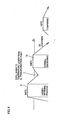
- Fig. 4 shows a heat treatment pattern according to which a material is cooled to a temperature lower than the A 1 transformation point in a quenching process and thereafter heated again to be finally quenched.
- steel for a bearing's component is first heated to a temperature for carbonitriding (e.g. 845°C) higher than the A 1 transformation point. At this temperature, the steel is subjected to carbonitriding process. At the temperature of a treatment T 1 , carbon and nitrogen are diffused in a steel matrix such that the carbon can sufficiently be included in the steel. Thereafter, at the temperature of treatment T 1 the steel for the bearing's component is subjected to oil quenching to be cooled down to a temperature lower than the A 1 transformation point. Then, the steel may be subjected to tempering at 180°C. This tempering, however, may be omitted.
- a temperature for carbonitriding e.g. 845°C
- the steel is again heated to a temperature (e.g. 800°C) of no less than the A 1 transformation point and less than the temperature applied to carbo-nitride the steel.
- a temperature e.g. 800°C
- the steel is maintained to be subjected to a treatment T 2 .
- the steel is subjected to oil quenching to be cooled down to a temperature lower than the A1 transformation point.
- the steel is subjected to tempering at 180°C.
- steel for a bearing's component is first heated to a temperature for carbonitriding (e.g. 845°C) higher than the A 1 transformation point. At this temperature, the steel is subjected to carbonitriding process. At the temperature of treatment T 1 , carbon and nitrogen are diffused in a steel matrix such that the carbon can sufficiently be included in the steel. Thereafter, the steel for the bearing's component is not quenched, but is cooled down to a temperature of no more than the A 1 transformation point. Thereafter, the steel is again heated to a temperature (e.g. 800°C) of no less than the A1 transformation point and less than the temperature applied to carbonitride the steel.
- a temperature for carbonitriding e.g. 845°C
- the steel is maintained to be subjected to treatment T 2 . Then, at the temperature of treatment T 2 , the steel is subjected to oil quenching to be cooled down to a temperature lower than the A 1 transformation point. Thereafter, the steel is subjected to tempering at 180°C.
- the above-discussed heat treatment can provide enhanced the crack strength and reduced secular dimensional variation rate while carbonitriding the surface layer.
- This heat treatment can also produce a microstructure having austenite crystal grains of a grain size which is smaller than the conventional one by one half or more.
- the transmission component subjected to the above-described heat treatment can have a long fatigue life (or a long rolling contact fatigue life when the component is a rolling bearing or a rolling bearing's component), an increased anti-crack strength, and a reduced secular dimensional variation rate.
- the above-described thermal treatments both allow their carbonitriding processes to produce a nitriding layer that is a "carbonitriding layer.” Since the material for the carbonitriding process, the steel, has a high concentration of carbon, carbon in the atmosphere of the normal carbonitriding process might not enter the surface of the steel easily. For example, with steel having a high concentration of carbon (approximately 1 % by weight), a carburized layer may have a higher concentration of carbon than this value, or a carburized layer may be formed without having a higher concentration of carbon than this value.
- a concentration of nitrogen in normal steel is typically as low as approximately no more than 0.025 wt % at the maximum although it depends on a concentration of Cr or the like. Therefore, a nitriding layer can apparently be formed regardless of the concentration of carbon in source steel. It will be appreciated that the above-described nitriding layer may also be enriched with carbon.
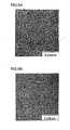
- Fig. 5A shows a grain size of austenite of a bearing steel having been heat-treated as shown in Fig. 3 .
- Fig. 5B shows a grain size of austenite of a bearing steel which has undergone the conventional heat treatment.
- Figs. 6A and 6B diagrammatically show the grain sizes of austenite that are shown in Figs. 5A and 5B .
- the grain diameter of the conventional austenite is 10 which is a grain size number defined by JIS (Japanese Industrial Standard) while that of the present invention through the heat treatment thereof is 12 and thus fine grains are seen.
- the average grain diameter in Fig. 5A is 5.6 ⁇ m measured by the intercept method.
- rolling bearings 10A and 10B as the support structure for the shaft were deep groove ball bearings.
- Rolling bearings 10A and 10B may be tapered roller bearings as shown in Fig. 7 or cylindrical roller bearings as shown Fig. 8 .
- the any one of the members includes steel having a nitriding layer and has an austenite grain with a grain size number falling within a range exceeding 10.
- the any one of the outer member (outer ring 1), the inner member (inner ring 2), and the rolling element (roller 3) of each of the tapered roller bearing in Fig. 7 and the cylindrical roller bearing in Fig. 8 is the transmission component in accordance with the present embodiment
- the any one of the members includes steel having a nitriding layer and has a fracture stress value of at least 2650 MPa.
- the any one of the members includes steel having a nitriding layer and has a hydrogen content in the steel that is at most 0.5 ppm.
- any one of the outer member (outer ring 1), the inner member (inner ring 2), and the rolling element (roller 3) of each of the tapered roller bearing in Fig. 7 and the cylindrical roller bearing in Fig. 8 is the transmission component in accordance with the present embodiment
- the any one of the members is formed by the method as described in Figs. 3 and 4 .
- the tapered roller bearing shown in Fig. 7 has, between outer ring 1 and inner ring 2, a plurality of tapered rollers (conical rollers) 3 held by cage 4.
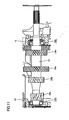
- This tapered roller bearing is designed such that the raceway surfaces of outer ring 1 and inner ring 2 and the vertex of a cone of roller 3 meet at a point on the center line of the bearing. Therefore, the resultant of forces from the raceway surfaces of outer ring 1 and inner ring 2 presses roller 3 against a large collar of inner ring 2 while guiding and rolling roller 3 along the raceway.
- the cylindrical roller bearing shown in Fig. 8 has, between outer ring 1 and inner ring 2, a plurality of cylindrical rollers 3 held by cage 4.
- the needle roller bearing shown in Fig. 9 has, between outer ring 1 and an inner ring portion (not shown), a plurality of needle rollers 3 held by cage 4.
- Roller 3 generally has a diameter of at most 5mm and a length 3 to 10 times as long as the diameter.
- the self-aligning roller bearing shown in Fig. 10 has, between outer ring 1 and inner ring 2, barrel-shaped rollers 3 arranged in two lines and held by cage 4. Such barrel-shaped rollers 3 arranged in two lines give a self-aligning ability capable of handling the inclination of the shaft or the like.
- a shaft 21 on which a plurality of gears 24a to 24d are provided is rotatably supported by housing 15 via tapered roller bearing 10A (or 10B).
- a shaft 31 on which a plurality of gears 34a to 34d are provided is rotatably supported by housing 15 via self-aligning roller bearing 10A.
- the transmission component incorporated into the transmission shown in Fig. 11 or 12 for example, at least one of the plurality of gears 24a to 24d, shaft 21, the outer member, the inner member, and the rolling element of tapered roller bearings 10A and 10B, housing 15, and the like shown in Fig. 11 , or at least one of the plurality of gears 34a to 34d, shaft 31, the outer member, the inner member, and the rolling element of self-aligning roller bearing 10A, housing 15, and the like shown in Fig. 12 ) has a nitriding layer at a surface layer and an austenite grain with a grain size number falling within a range exceeding 10.
- the transmission component incorporated into the transmission shown in Fig. 11 or 12 (for example, at least one of the plurality of gears 24a to 24d, shaft 21, the outer member, the inner member, and the rolling element of tapered roller bearings 10A and 10B, housing 15, and the like shown in Fig. 11 , or at least one of the plurality of gears 34a to 34d, shaft 31, the outer member, the inner member, and the rolling element of self-aligning roller bearing 10A, housing 15, and the like shown in Fig. 12 ) has a nitriding layer at a surface layer and a fracture stress value of at least 2650 MPa.
- the transmission component incorporated into the transmission shown in Fig. 11 or 12 (for example, at least one of the plurality of gears 24a to 24d, shaft 21, the outer member, the inner member, and the rolling element of tapered roller bearings 10A and 10B, housing 15, and the like shown in Fig. 11 , or at least one of the plurality of gears 34a to 34d, shaft 31, the outer member, the inner member, and the rolling element of self-aligning roller bearing 10A, housing 15, and the like shown in Fig. 12 ) has a nitriding layer at a surface layer and a hydrogen content in the steel that is at most 0.5 ppm.
- rolling bearing 10C as the support structure for the shaft was a needle roller bearing.
- Rolling bearing 10C may be the deep groove ball bearing as shown in Fig. 2 , the tapered roller bearing as shown in Fig. 7 , the cylindrical roller bearing as shown in Fig. 8 , the needle roller bearing (the configuration having an outer ring or an inner ring) as shown in Fig. 9 , or the self-aligning roller bearing as shown in Fig. 10 .
- the constant-mesh transmission has mainly been described in the above embodiment.
- the present invention is not limited to this type of transmission.
- the present invention is also applicable to other types of transmissions such as a sliding-mesh transmission or a synchro-mesh transmission.
- JIS-SUJ2 (1.0 wt% of C - 0.25 wt% of Si - 0.4 wt% of Mn - 1.5 wt% of Cr) was used for Example 1 which is not part of the present invention. Samples shown in Table 1 were each produced through the procedure described below. Table 1 Samples A B C D E F Conventionally carbonitrited product Normally quenched product Secondary quenching temp.(°C) 780 1) 800 815 830 850 870 - - Hydrogen content (ppm) - 0.37 0.40 0.38 0.42 0.40 0.72 0.38 Grain size No.
- Carbonitriding was performed at 850°C held for 150 minutes in an atmosphere of a mixture of RX gas and ammonia gas. Following the heat treatment pattern shown in Fig. 3 , primary quenching was done from a carbonitriding temperature of 850°C, and secondary quenching was subsequently done by heating to a temperature in a temperature range from 780°C to 830°C lower than the carbonitriding temperature. Sample A with a secondary quenching temperature of 780°C was not tested since quenching of sample A was insufficient.
- samples were carbonitrided through the same procedure as that of samples A-D of the present invention, and then secondary quenched at a temperature from 850°C to 870°C equal to or higher than the carbonitriding temperature of 850°C.
- Carbonitriding was performed at 850°C held for 150 minutes in an atmosphere of a mixture of RX gas and ammonia gas. Quenching was successively done from the carbonitriding temperature and no secondary quenching was done.
- quenching was done by increasing the temperature to 850°C and no secondary quenching was done.
- the amount of hydrogen was determined by means of a DH-103 hydrogen determinator manufactured by LECO Corporation to analyze the amount of non-diffusible hydrogen in a steel. The amount of diffusible hydrogen was not measured. Specifications of the LECO DH-103 hydrogen determinator are as follows.
- a sample was taken by a dedicated sampler and the sample together with the sampler was put into the hydrogen determiner. Diffusible hydrogen therein was directed by the nitrogen carrier gas to a thermal conductimetry detector. The diffusible hydrogen was not measured in this example. Then, the sample was taken out of the sampler to be heated in a resistance heater and non-diffusible hydrogen was directed by the nitrogen carrier gas to the thermal conductimetry detector. The thermal conductivity was measured by the thermal conductimetry detector to determine the amount of non-diffusible hydrogen.
- the crystal grain size was measured according to the method of testing the crystal grain size of austenite in a steel defined by JIS G 0551.
- a Charpy impact test was conducted according to the Charpy impact test method for a metal material defined by JIS Z 2242.
- a test piece used here was a U-notch test piece (JIS No. 3 test piece) defined by JIS Z 2202. Note that a Charpy impact value is a value of absorption energy E, as described below, that is divided by cross section (0.8 cm 2 ).
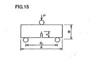
- Fig. 13 shows a test piece utilized for the measurement of fracture stress. Amsler universal testing machine was employed. A load was exerted in direction P in the figure and the load when the test piece was fractured was measured. Then, the measured load which was a fracture load was converted into a stress by the following stress calculation formula for a curved beam. It is noted that the test piece to be used is not limited to the one shown in Fig. 13 and may be any test piece having a different shape.
- ⁇ 1 and ⁇ 2 are determined by the following formula (JSME Mechanical Engineer's Handbook, A4-strength of materials, A4-40).
- N indicates an axial force of a cross section including the axis of the annular test piece
- A indicates a cross-sectional area
- e 1 indicates an outer radius
- e 2 indicates an inner radius
- ⁇ is a section modulus of the curbed beam.
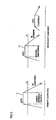
- the rolling fatigue life tester is shown in Figs. 14A and 14B in its simplified form, and test conditions for a rolling fatigue life test are shown in Table 2.
- a test piece 221 undergoing the rolling fatigue life test was driven by a driving roll 211 to rotate while being in contact with balls 213.
- Balls 213 were (3/4)" balls guided by a guiding roll 212 to roll. Balls 213 exerted a high surface pressure on test piece 221 while test piece 221 also exerted a high surface pressure on balls 213.
- Table 1 shows that the conventional carbonitrided sample without being additionally processed has a considerably large hydrogen amount in the steel that is 0.72 ppm. A reason therefor is considered that ammonia (NH 3 ) contained in the atmosphere in the carbonitriding process is decomposed and then hydrogen enters the steel. On the other hand, the hydrogen amount in the steel of samples B-F is reduced to 0.37 - 0.42 ppm and thus almost a half of that of the conventional sample. This amount of hydrogen in the steel is substantially equal in level to that of the normal quenched sample.
- the above-mentioned reduction of the hydrogen amount in the steel can lessen the degree of embrittlement of the steel that is due to hydrogen in the solid solution.
- the reduction of the hydrogen amount the Charpy impact value and the fracture stress value of samples B-F of the present invention are remarkably improved.
- samples that are secondary quenched at a temperature lower than the quenching temperature in the carbonitriding process (primary quenching), namely samples B-D have austenite grains which are remarkably made fine, i.e., crystal grain size number is 11-12.
- Samples E and F as well as the conventional carbonitrided sample and the normal quenched sample have austenite grains with the crystal grain size number of 10, which means that the crystal grain size of samples E and F is greater than that of samples B-D.
- Table 1 shows that the Charpy impact value of the conventional carbonitrided sample is 5.33 J/cm 2 while those of samples B-F of the present invention are higher, ranging from 6.20 to 6.65 J/cm 2 . It is also seen from this that a lower secondary quenching temperature leads to a higher Charpy impact value.
- the normal quenched sample has a high Charpy impact value of 6.70 J/cm 2 .
- the fracture stress corresponds to anti-crack strength. It is seen from Table 1 that the fracture stress of the conventional carbonitrided sample is 2330 MPa. On the other hand, the fracture stresses of samples B-F are improved to 2650-2840 MPa. The normal quenched sample has a fracture stress of 2770 MPa which is in the range of the fracture stress of samples B-F. It is considered that the reduction in hydrogen content greatly contributes to the improved anti-crack strength of samples B-F as well as the reduction in size of austenite crystal grains.
- the normal quenched sample has the shortest rolling fatigue life (L 10 ) due to the absence of a nitriding layer in the surface layer.
- the rolling fatigue life of the conventional carbonitrided sample is 3.1 times as long as that of the normal quenched sample.
- the rolling fatigue life of samples B-D is remarkably improved as compared with the conventional carbonitrided sample.
- Samples E and F have the rolling fatigue life almost equal to that of the conventional carbonitrided sample.
- the hydrogen content in the steel can be reduced in samples B to F.
- the improved fracture stress and Charpy impact values can be achieved in samples B to F.
- the rolling contact fatigue life should desirably be improved. This can be achieved only in samples B to D having even smaller grains with an austenite grain size number of at least approximately 11.
- Samples B to F correspond to examples not in accordance with the present invention, however, the more desirable scope is that corresponding to samples B to D that have been subjected to the secondary quenching at a temperature lower than that applied to carbo-nitride the steel and thus has even smaller grains.
- Test conditions and the test device for the rolling fatigue life test are as shown in Table 2 and Fig. 7 .
- Results of the rolling fatigue life test are shown in Table 3.
- Table 2 Test piece ⁇ 12 ⁇ L22 cylindrical test piece Number of tested pieces 10 Counterpart steel ball 3/4" (19.05 mm) Contact surface pressure 5.88 GPa Load speed 46240 cpm Lubricant oil Turbine VG68 - forced circulation lubrication Table 3 Test Result Sample Life (load count) Relative L 10 L 10 ( ⁇ 10 4 times) L 10 ( ⁇ 10 4 times) A 8017 18648 1.0 B 24656 33974 3.1 C 43244 69031 5.4
- carbonitrided sample B (comparative example) has a rolling fatigue life (L 10 life: one out of ten test pieces being damaged) that is 3.1 times as long as that of sample A (comparative example) which undergoes normal quenching only, and thus it is seen that the effect of extending the life is obtained through the carbonitriding process.
- sample C of the present invention has a longer life which is 1.74 times as long as that of sample B and 5.4 times as long as that of sample A. It is considered that this improvement is obtained mainly from the fine microstructure.
- Sample C of an example of the present invention achieved a Charpy impact value equal to that of sample A (comparative example) having undergone only normal quenching and higher than that of carbonitrided sample B (comparative example).
- the test piece shown in Fig. 15 was used for the static fracture toughness test.
- a pre-crack of approximately 1 mm was made, thereafter a static load P by three-point bending was added, and then a fracture load was determined.
- a fracture toughness value K Ic value
- K 1 ⁇ c PL ⁇ a / BW 2 5.8 - 9.2 a / W + 43.6 ⁇ a / W 2 - 75.3 ⁇ a / W 3 + 77.5 ⁇ a / W 4
- sample C example of the present invention achieves a fracture toughness value (K 1C value) approximately 1.2 times as high as those of samples A and B (comparative examples).
- Carbonitrided sample B (comparative example) has a value of a static-pressure fracture-strength slightly smaller than that of sample A (comparative example) having been subjected to normal quenching alone.
- sample C of an example of the present invention has a static-pressure fracture-strength value considerably higher than that of sample B and slightly higher than that of sample A.
- Table 7 shows the rate of secular dimensional variation measured under the conditions of 130 DEG C (holding temperature) and 500 hours (holding time), together with the surface hardness and the amount of retained austenite (at 0.1 mm depth from the surface).
- Table 7 Sample Number tested surface hardness (HRC) Retained ⁇ (%) Rate of dimensional change ( ⁇ 10 -5 ) Relative Rate of dimensional change *) A 3 62.5 9.0 18 1.0 B 3 63.6 28.0 35 1.9 C 3 60.0 11.3 22 1.2 *: smaller is superior
- sample C of an example of the present invention has a lower rate of dimensional variation.
- Sample B (comparative example) having undergone carbonitriding has a lifetime which is approximately 2.5 times as long as that of sample A, and sample C of the present invention has a lifetime which is approximately 3.7 times as long as that of sample A. While sample C of the present invention has a smaller amount of retained austenite than that of sample B of the comparative example, sample C has a long lifetime because of influences of entering nitrogen and the fine microstructure.
- sample C of the present invention namely a bearing component serving as a support structure in a transmission produced by the heat treatment method of the present invention can simultaneously achieve three goals: extension of the rolling fatigue life that has been difficult to achieve by the conventional carbonitriding, improvement in crack strength and reduction of the rate of secular dimensional variation.
- austenite grains refer to crystal grains of austenite which is phase-transformed during the heating process, and the traces of grains remain after the austenite is transformed into martensite through cooling.
- the nitriding layer is formed and in addition, a superior fracture stress value not heretofore achieved can be obtained. Therefore, the anti-crack strength or the like can be improved in the present invention. Additionally, the transmission can be downsized.
- the needle roller bearing may be a full type roller bearing or a shell type needle roller bearing.
Description
- The present invention relates to a transmission component having a long rolling contact fatigue life, an increased anti-crack strength, or a reduced secular variation in dimension, and to a method of manufacturing the same and a tapered roller bearing.
- To increase a bearing's components in life, a thermal treatment is performed. Specifically, for example, in quenching the components they are heated in an ambient RX gas with ammonium gas further introduced therein to carbo-nitride their surface layer portion, for example as disclosed in Japanese Patent Laying-Open Nos.
8-4774 11-101247 EP 0 600 421 A1 . - The above-mentioned carbonitriding process is a process to diffuse carbon and nitrogen. This requires a high temperature maintained for a long period of time. As such, for example a coarsened structure results and increased anti-crack strength is hardly obtained. Furthermore, as more austenite is retained, secular dimensional variation rate increases, which is also a problem in this carbonitriding process.
- Against rolling fatigue, an increased life can be ensured, an enhanced anti-crack strength provided and an increased secular dimensional variation avoided by relying on designing a steel alloy to provide an adjusted composition. Relying on designing the alloy, however, increases source material cost disadvantageously.
- Future bearings in a transmission will be used in environments exerting large loads at high temperatures. In addition, they will be required to be employed in a downsized transmission. Therefore, the bearings will be required to be operable under larger loads at higher temperatures than conventional. As such, there is a demand for a bearing having large strength, long life against rolling contact fatigue, and large anti-crack strength and dimensional stability.
- It is an object of the present invention to provide a transmission component having an increased anti-crack strength, an enhanced dimensional stability, and a long fatigue life (or a long rolling contact fatigue life in the case of a tapered roller bearing or when the component is a rolling bearing or a rolling bearing's component), and a method of manufacturing the same.
- The present invention provides a transmission component incorporated into a transmission capable of changing a rotational speed of an output shaft relative to a rotational speed of an input shaft by means of mesh of toothed wheels. The transmission component is a rolling bearing component. The component has a nitriding layer at a surface layer formed by a carbonitrding process, and an austenite grain with a grain size number measured in accordance with Japanese Standard JIS G 0551 falling within a range exceeding 10. The component has a fracture stress value of at least 2650 MPa and a hydrogen content of a most 0.5 ppm. The component is formed of JIS-SUJ2.
- In the transmission component according to the present invention, a small austenite grain size allows significantly increased anti-crack strength, dimensional stability and fatigue life (or rolling contact fatigue life when the component is a rolling bearing or a rolling bearing's component). With the austenite grain size number of 10 or less, any remarkable improvement of the fatigue life is impossible and thus the grain size number is greater than 10, and preferably 11 or greater. Although further finer austenite grains are desirable, the grain size number exceeding 13 is usually difficult to achieve. Note that an austenite grain of the transmission component does not vary whether it may be in a surface layer portion significantly affected as it is carbonitrided or a portion inner than the surface layer portion. As such, the surface layer portion and the inner portion will be set as positions serving as subjects of the aforementioned grain number range.
- The present inventors have found that steel that is carbonitrided at a temperature exceeding an A1 transformation point and then cooled to a temperature of less than the A1 transformation point, and subsequently reheated to a range of temperature higher than the A1 transformation point and is quenched, can be provided with a nitriding layer allowing the steel to provide a fracture stress value of no less than 2650 MPa, which has conventionally not been achieved. A transmission component superior in fracture stress to conventional and thereby larger in strength can thus be obtained.
- In the transmission component according to the present invention, embrittlement of steel attributed to hydrogen can be alleviated. If steel has a hydrogen content exceeding 0.5 ppm the steel has reduced anti-crack strength. Such a steel is insufficiently suitable for a support structure for a hub experiencing heavy loads. A lower hydrogen content is desirable. However, reduction of the hydrogen content to the one less than 0.3 ppm requires long-term heat treatment, resulting in increase in size of austenite grains and thus deterioration in toughness. Then, a hydrogen content is desirably in a range from 0.3 to 0.5 ppm and more desirably in a range from 0.35 to 0.45 ppm.
- In measuring the above hydrogen content, diffusible hydrogen is not measured and only the non-diffusible hydrogen released from the steel at a predetermined temperature or higher is measured. Diffusible hydrogen in a sample of small size is released from the sample to be scattered even at room temperature, and therefore the diffusible hydrogen is not measured. Non-diffusible hydrogen is trapped in any defect in the steel and only released from the sample at a predetermined heating temperature or higher. Even if only the non-diffusible hydrogen is measured, the hydrogen content considerably varies depending on the method of measurement. The above mentioned range of hydrogen content is determined by thermal conductimetry. In addition, as detailed later, the measurement may be taken by means of a LECO DH-103 hydrogen determinator or like measuring device.
- The above-described rolling bearing component is preferably provided in a form of rolling bearing rotatably supporting the input shaft, the output shaft, or each of the toothed wheels, and the rolling bearing is a tapered roller bearing.
- The above-described rolling bearing component is preferably provided in a form of rolling bearing rotatably supporting the input shaft, the output shaft, or each of the toothed wheels, and the rolling bearing is a needle roller bearing.
- The above-described rolling bearing component is preferably provide in a form of rolling bearing rotatably supporting the input shaft, the output shaft, or each of the toothed wheels, and the rolling bearing is a ball roller bearing.
- The present invention further provides a method of manufacturing a transmission component incorporated into a transmission capable of changing a rotational speed of an output shaft relative to a rotational speed of an input shaft by means of mesh of toothed wheels. At least one of an outer ring and an inner ring of each of a tapered roller bearing and a cylindrical roller bearing is the roller bearing component, wherein the any one of the inner ring and the outer ring of the component is formed at least by carbonitriding steel for the bearing's component at a temperature higher than an A1 transformation point and then not quenching, but cooling the steel to a temperature lower than the A1 transformation point and subsequently reheating the steel to a range of temperature of no less than the A1 transformation point and less than the temperature applied to carbo-nitride the steel, and quenching the steel, wherein said range of temperature at which the quenching begins is 790°C to 830°C..
- In the present method of manufacturing the roller bearing's component, after steel is carbonitrided the steel is cooled to a temperature of less than the A1 transformation point before it is finally quenched. A fine austenite grain size can be obtained and as a result, Charpy impact, fracture toughness, anti-crack strength, fatigue life (or rolling contact fatigue life when the component is a rolling bearing or a rolling bearing's component) and the like can be improved.
- Furthermore for example by cooling to a temperature at which austenite transforms, austenite grain boundary in carbonitriding can be irrelevant to that in final quenching. Furthermore, the final quenching temperature is lower than the carbonitriding temperature, and thus the amount of un-dissolved cementite in the surface layer, which is influenced by the carbonitriding process, increases as compared with that in the carbonitriding process. As such the ratio of undissolved cementite increases while the ratio of austenite decreases at the heating temperature in the final quenching as compared with those ratios in the carbonitriding process. In addition, it is seen from the Fe-C binary phase diagram that, in the range where cementite and austenite coexist, the concentration of carbon in solid solution of the carbon and austenite decreases as the quenching temperature decreases.
- When the temperature is increased to the final quenching temperature, austenite grains are made fine since there remain a large amount of un-dissolved cementite that prevent growth of austenite grains. Moreover, the structure transformed from austenite to martensite through quenching has a low carbon concentration, so that the structure has high toughness as compared with the structure quenched from the carbonitriding temperature.
- The steel is again heated to a temperature hardly allowing an austenite grain to be grown before the steel is quenched. Fine austenite grain size can thus be achieved.
- The inner and outer rings in this specification may be integrated with a member such as a shaft or a housing, or may be provided separately from such a member.
- The austenite grain also refers to a trace thereof remaining after the austenite is transformed into ferrite phase such as martensite or bainite through quenching. An austenite grain boundary before quenching is sometimes referred to as a "prior austenite grain boundary" to be distinguished from the remaining austenite grain after quenching. That is, the "austenite grain" and the "prior austenite grain boundary" are used to mean the same.
- The prior austenite grain boundaries can be observed after being subjected to a process developing a grain boundary such as an etching process for a metal phase sample of the member of interest. For measurement of the grain size, the average of ASTM (American Society for Testing and Material) defined grain size numbers (= average grain size of at most 8 mu m) may be converted to obtain an average grain diameter, or the intercept method or the like may be used in which a straight line is placed on a metal phase structure in an arbitrary direction to obtain an average length between points at which the straight line meets grain boundaries. The above-described nitriding layer is formed by a carbonitriding process as will be described below. The nitriding layer may or may not be enriched with carbon. The foregoing and other objects, features, aspects and advantages of the present invention will become more apparent from the following detailed description of the present invention when taken in conjunction with the accompanying drawings.
-
-
Fig. 1 is a schematic cross-sectional view of the configuration of a transmission into which a transmission component is incorporated in accordance with one embodiment of the present invention. -
Fig. 2 is a schematic cross-sectional view of the configuration of a deep groove ball bearing serving as rollingbearings Fig. 1 . -
Fig. 3 is a diagram for illustrating a method of a thermal treatment applied to the transmission component in an embodiment not part of the present invention. -
Fig. 4 is a diagram for illustrating an exemplary variation of the method of the thermal treatment applied to the transmission component in the embodiment of the present invention. -
Fig. 5A shows a microstructure, more specifically, austenite grain of a bearing which is not part of the present invention, andFig. 5B shows a microstructure, more specifically, austenite grain of a bearing in the background art. -
Fig. 6A is a drawing of the austenite grain boundary shown inFig. 5A , andFig. 6B is a drawing of the austenite grain boundary shown inFig. 5B . -
Fig. 7 is a schematic cross-sectional view of the configuration of a tapered roller bearing. -
Fig. 8 is a schematic cross-sectional view of the configuration of a cylindrical roller bearing. -
Fig. 9 is a schematic cross-sectional view of the configuration of a needle roller bearing. -
Fig. 10 is a schematic cross-sectional view of the configuration of a self-aligning roller bearing. -
Fig. 11 is a schematic diagram showing the configuration in which the tapered roller bearing shown inFig. 7 is utilized as a support structure of a shaft in a transmission. -
Fig. 12 is a schematic diagram showing the configuration in which the self-aligning roller bearing shown inFig. 10 is utilized as a support structure of a shaft in a transmission. -
Fig. 13 shows a sample used in a static pressure fracture strength test (to measure fracture stress). -
Fig. 14A is a schematic front view of a rolling contact fatigue life tester, andFig. 14B is a schematic side view of the rolling contact fatigue life tester. -
Fig. 15 shows a sample used in a static fracture toughness test. - In the following, embodiments of the present invention will be described with reference to the drawings.
- Referring to
Fig. 1 , this transmission is a constant mesh transmission mainly including rollingbearings 10A to 10F, aninput shaft 11, anoutput shaft 12, acounter shaft 13, gears (toothed wheels) 14a to 14k, and ahousing 15. -
Input shaft 11 is rotatably supported byhousing 15 via rollingbearing 10A. Gear 14a is provided at the outer peripheral portion of thisinput shaft 11, and gear 14b is provided at the inner peripheral portion thereof. - One side of
output shaft 12 is rotatably supported byhousing 15 via rollingbearing 10B, while the other side ofoutput shaft 12 is rotatably supported byinput shaft 11 via rollingbearing 10C. Thisoutput shaft 12 is provided withgears 14c to 14g. The axial load of thesegears 14c to 14g is supported by rollingbearing 10F that is a thrust needle roller bearing. -
Gears gears output shaft 12 via rollingbearing 10D.Gear 14e is mounted onoutput shaft 12 such that it rotates withoutput shaft 12 and is slidable in the axial direction ofoutput shaft 12. -
Gears 14f and 14g are each provided at the outer peripheral portion of a single member. The member withgears 14f and 14g is mounted onoutput shaft 12 such that it rotates withoutput shaft 12 and is slidable in the axial direction ofoutput shaft 12. When the member withgears 14f and 14g slides to the left in the figure, gear 14f can mesh with gear 14b. When the member withgears 14f and 14g slides to the right in the figure,gear 14g can mesh withgear 14d. -
Counter shaft 13 is secured tohousing 15.Counter shaft 13 rotatably supports a gearmember having gears 14h to 14k or the like via rollingbearing 10E.Gear 14h is in constant mesh with gear 14a, andgear 14i is in constant mesh withgear 14c. Whengear 14e slides to the left in the figure,gear 14j can mesh withgear 14e. Whengear 14e slides to the right in the figure,gear 14k can mesh withgear 14e. - In the present embodiment, the support structure for
input shaft 11 has rollingbearings output shaft 12 has rollingbearings Rolling bearings gears bearings 10D to 10F.Rolling bearings - Referring to
Fig. 2 , deepgroove ball bearings housing 15, an inner ring 2 (an inner member) secured to inputshaft 11 oroutput shaft 12, a plurality ofballs 3 rolling betweenouter ring 1 andinner ring 2, and acage 4 holding the plurality ofballs 3 in place with a constant space therebetween. - Referring back to
Fig. 1 , the needle roller bearing serving as rolling bearing 10C has a cage and roller configuration in which a plurality ofneedle rollers 3b are held by a cage. In this configuration, an outer member of rolling bearing 10C is integrated withinput shaft 11, while an inner member thereof is integrated withoutput shaft 12. - The needle roller bearings serving as rolling
bearings needle rollers 3b are held by a cage. In this configuration, outer members of the rolling bearings are integrated withgears 14c to 14k, while inner members thereof are integrated withoutput shaft 12 orcounter shaft 13. The thrust needle roller bearing serving as rolling bearing 10F has anouter ring 1c (an outer member) secured to countershaft 13, aninner ring 2c (an inner member) secured to the gearmember having gears 14h to 14k, a plurality ofneedle rollers 3c rolling betweenouter ring 1 c andinner ring 2c, and a cage holding the plurality ofneedle rollers 3c in place with a constant space therebetween. - The transmission component incorporated into the above-described transmission (for example, at least one of the outer member, the inner member, and the rolling element of rolling
bearings 10A to 10F,input shaft 11,output shaft 12,counter shaft 13, gears (toothed wheels) 14a to 14k,housing 15, and the like) has a nitriding layer at a surface layer and an austenite grain with a grain size number falling within a range exceeding 10. - Particularly when at least any one of the outer member, the inner member, and the rolling element of each of rolling
bearings 10A to 10F is the transmission component in accordance with the present embodiment, at least any one of the outer member (outer ring 1, an outer ring portion ofoutput shaft 12, or gears 14c, 14h to 14k), the inner member (inner ring 2, an inner ring portion ofinput shaft 11, an inner ring portion ofoutput shaft 12, or an inner ring portion of counter shaft 13), and the rolling element (ball 3 orneedle rollers - Furthermore, the transmission component incorporated into the above-described transmission (for example, at least one of the outer member, the inner member, and the rolling element of rolling
bearings 10A to 10F,input shaft 11,output shaft 12,counter shaft 13, gears (toothed wheels) 14a to 14k,housing 15, and the like) has a nitriding layer at a surface layer and a fracture stress value of at least 2650 MPa. - Particularly when at least any one of the outer member, the inner member, and the rolling element of each of rolling
bearings 10A to 10F is the transmission component in accordance with the present embodiment, at least any one of the outer member (outer ring 1, the outer ring portion ofoutput shaft 12, or gears 14c, 14h to 14k), the inner member (inner ring 2, the inner ring portion ofinput shaft 11, the inner ring portion ofoutput shaft 12, or the inner ring portion of counter shaft 13), and the rolling element (ball 3 orneedle rollers - Furthermore, the transmission component incorporated into the above-described transmission (for example, at least one of the outer member, the inner member, and the rolling element of rolling
bearings 10A to 10F,input shaft 11,output shaft 12,counter shaft 13, gears (toothed wheels) 14a to 14k,housing 15, and the like) has a nitriding layer at a surface layer and a hydrogen content in steel that is at most 0.5 ppm. - Particularly when at least any one of the outer member, the inner member, and the rolling element of each of rolling
bearings 10A to 10F is the transmission component in accordance with the present embodiment, at least any one of the outer member (outer ring 1, the outer ring portion ofoutput shaft 12, or gears 14c, 14h to 14k), the inner member (inner ring 2, the inner ring portion ofinput shaft 11, the inner ring portion ofoutput shaft 12, or the inner ring portion of counter shaft 13), and the rolling element (ball 3 orneedle rollers - In the following, a description will be given about a speed-change operation of this transmission.
- When gear 14f does not mesh with gear 14b,
gear 14g does not mesh withgear 14d, andgear 14e meshes withgear 14j, the driving force ofinput shaft 11 is transmitted tooutput shaft 12 viagears - When
gear 14g meshes withgear 14d andgear 14e does not mesh withgear 14j, the driving force ofinput shaft 11 is transmitted tooutput shaft 12 viagears - When gear 14f meshes with gear 14b and
gear 14e does not mesh withgear 14j, the mesh of gears 14b and 14f couples inputshaft 11 directly tooutput shaft 12 so that the driving force ofinput shaft 11 is transmitted directly tooutput shaft 12. The transmission in this state is in the third gear (high gear), for example. - In the following, a description will be given about a heat treatment including a carbonitriding process performed on the transmission component according to the present embodiment.
-
Fig. 3 shows a heat treatment pattern according to which primary quenching and secondary quenching are carried out, andFig. 4 shows a heat treatment pattern according to which a material is cooled to a temperature lower than the A1 transformation point in a quenching process and thereafter heated again to be finally quenched. - Referring to
Fig. 3 , steel for a bearing's component is first heated to a temperature for carbonitriding (e.g. 845°C) higher than the A1 transformation point. At this temperature, the steel is subjected to carbonitriding process. At the temperature of a treatment T1, carbon and nitrogen are diffused in a steel matrix such that the carbon can sufficiently be included in the steel. Thereafter, at the temperature of treatment T1 the steel for the bearing's component is subjected to oil quenching to be cooled down to a temperature lower than the A1 transformation point. Then, the steel may be subjected to tempering at 180°C. This tempering, however, may be omitted. - Thereafter, the steel is again heated to a temperature (e.g. 800°C) of no less than the A1 transformation point and less than the temperature applied to carbo-nitride the steel. At this temperature, the steel is maintained to be subjected to a treatment T2. Then, at the temperature of treatment T2, the steel is subjected to oil quenching to be cooled down to a temperature lower than the A1 transformation point. Thereafter, the steel is subjected to tempering at 180°C.
- Referring to
Fig. 4 , steel for a bearing's component is first heated to a temperature for carbonitriding (e.g. 845°C) higher than the A1 transformation point. At this temperature, the steel is subjected to carbonitriding process. At the temperature of treatment T1, carbon and nitrogen are diffused in a steel matrix such that the carbon can sufficiently be included in the steel. Thereafter, the steel for the bearing's component is not quenched, but is cooled down to a temperature of no more than the A1 transformation point. Thereafter, the steel is again heated to a temperature (e.g. 800°C) of no less than the A1 transformation point and less than the temperature applied to carbonitride the steel. At this temperature, the steel is maintained to be subjected to treatment T2. Then, at the temperature of treatment T2, the steel is subjected to oil quenching to be cooled down to a temperature lower than the A1 transformation point. Thereafter, the steel is subjected to tempering at 180°C. - Compared with ordinary or normal quenching (by which carbonitriding is done and immediately thereafter quenching is done once), the above-discussed heat treatment can provide enhanced the crack strength and reduced secular dimensional variation rate while carbonitriding the surface layer. This heat treatment can also produce a microstructure having austenite crystal grains of a grain size which is smaller than the conventional one by one half or more. The transmission component subjected to the above-described heat treatment can have a long fatigue life (or a long rolling contact fatigue life when the component is a rolling bearing or a rolling bearing's component), an increased anti-crack strength, and a reduced secular dimensional variation rate.
- The above-described thermal treatments both allow their carbonitriding processes to produce a nitriding layer that is a "carbonitriding layer." Since the material for the carbonitriding process, the steel, has a high concentration of carbon, carbon in the atmosphere of the normal carbonitriding process might not enter the surface of the steel easily. For example, with steel having a high concentration of carbon (approximately 1 % by weight), a carburized layer may have a higher concentration of carbon than this value, or a carburized layer may be formed without having a higher concentration of carbon than this value. A concentration of nitrogen in normal steel, however, is typically as low as approximately no more than 0.025 wt % at the maximum although it depends on a concentration of Cr or the like. Therefore, a nitriding layer can apparently be formed regardless of the concentration of carbon in source steel. It will be appreciated that the above-described nitriding layer may also be enriched with carbon.
-
Fig. 5A shows a grain size of austenite of a bearing steel having been heat-treated as shown inFig. 3 . For comparison,Fig. 5B shows a grain size of austenite of a bearing steel which has undergone the conventional heat treatment.Figs. 6A and 6B diagrammatically show the grain sizes of austenite that are shown inFigs. 5A and 5B . In the structures with the crystal grain sizes of austenite, the grain diameter of the conventional austenite is 10 which is a grain size number defined by JIS (Japanese Industrial Standard) while that of the present invention through the heat treatment thereof is 12 and thus fine grains are seen. Further, the average grain diameter inFig. 5A is 5.6 µm measured by the intercept method. - In the following, a description will be given about a modification of the support structure for the shaft in the transmission.
- In the configuration shown in
Fig. 1 , rollingbearings Rolling bearings Fig. 7 or cylindrical roller bearings as shownFig. 8 . - When at least any one of an outer member (outer ring 1), an inner member (inner ring 2), and a rolling element (roller 3) of each of the tapered roller bearing in
Fig. 7 and the cylindrical roller bearing inFig. 8 is the transmission component in accordance with the present embodiment, the any one of the members includes steel having a nitriding layer and has an austenite grain with a grain size number falling within a range exceeding 10. - Furthermore, when at least any one of the outer member (outer ring 1), the inner member (inner ring 2), and the rolling element (roller 3) of each of the tapered roller bearing in
Fig. 7 and the cylindrical roller bearing inFig. 8 is the transmission component in accordance with the present embodiment, the any one of the members includes steel having a nitriding layer and has a fracture stress value of at least 2650 MPa. - Moreover, when at least any one of the outer member (outer ring 1), the inner member (inner ring 2), and the rolling element (roller 3) of each of the tapered roller bearing in
Fig. 7 and the cylindrical roller bearing inFig. 8 is the transmission component in accordance with the present embodiment, the any one of the members includes steel having a nitriding layer and has a hydrogen content in the steel that is at most 0.5 ppm. - When at least any one of the outer member (outer ring 1), the inner member (inner ring 2), and the rolling element (roller 3) of each of the tapered roller bearing in
Fig. 7 and the cylindrical roller bearing inFig. 8 is the transmission component in accordance with the present embodiment, the any one of the members is formed by the method as described inFigs. 3 and4 . - The tapered roller bearing shown in
Fig. 7 has, betweenouter ring 1 andinner ring 2, a plurality of tapered rollers (conical rollers) 3 held bycage 4. This tapered roller bearing is designed such that the raceway surfaces ofouter ring 1 andinner ring 2 and the vertex of a cone ofroller 3 meet at a point on the center line of the bearing. Therefore, the resultant of forces from the raceway surfaces ofouter ring 1 andinner ring 2 pressesroller 3 against a large collar ofinner ring 2 while guiding and rollingroller 3 along the raceway. - The cylindrical roller bearing shown in
Fig. 8 has, betweenouter ring 1 andinner ring 2, a plurality ofcylindrical rollers 3 held bycage 4. - The needle roller bearing shown in
Fig. 9 has, betweenouter ring 1 and an inner ring portion (not shown), a plurality ofneedle rollers 3 held bycage 4.Roller 3 generally has a diameter of at most 5mm and alength 3 to 10 times as long as the diameter. - The self-aligning roller bearing shown in
Fig. 10 has, betweenouter ring 1 andinner ring 2, barrel-shapedrollers 3 arranged in two lines and held bycage 4. Such barrel-shapedrollers 3 arranged in two lines give a self-aligning ability capable of handling the inclination of the shaft or the like. - Referring to
Fig. 11 , ashaft 21 on which a plurality ofgears 24a to 24d are provided is rotatably supported byhousing 15 via taperedroller bearing 10A (or 10B). - Referring to
Fig. 12 , ashaft 31 on which a plurality of gears 34a to 34d are provided is rotatably supported byhousing 15 via self-aligningroller bearing 10A. - The transmission component incorporated into the transmission shown in
Fig. 11 or12 (for example, at least one of the plurality ofgears 24a to 24d,shaft 21, the outer member, the inner member, and the rolling element of taperedroller bearings housing 15, and the like shown inFig. 11 , or at least one of the plurality of gears 34a to 34d,shaft 31, the outer member, the inner member, and the rolling element of self-aligningroller bearing 10A,housing 15, and the like shown inFig. 12 ) has a nitriding layer at a surface layer and an austenite grain with a grain size number falling within a range exceeding 10. - The transmission component incorporated into the transmission shown in
Fig. 11 or12 (for example, at least one of the plurality ofgears 24a to 24d,shaft 21, the outer member, the inner member, and the rolling element of taperedroller bearings housing 15, and the like shown inFig. 11 , or at least one of the plurality of gears 34a to 34d,shaft 31, the outer member, the inner member, and the rolling element of self-aligningroller bearing 10A,housing 15, and the like shown inFig. 12 ) has a nitriding layer at a surface layer and a fracture stress value of at least 2650 MPa. - The transmission component incorporated into the transmission shown in
Fig. 11 or12 (for example, at least one of the plurality ofgears 24a to 24d,shaft 21, the outer member, the inner member, and the rolling element of taperedroller bearings housing 15, and the like shown inFig. 11 , or at least one of the plurality of gears 34a to 34d,shaft 31, the outer member, the inner member, and the rolling element of self-aligningroller bearing 10A,housing 15, and the like shown inFig. 12 ) has a nitriding layer at a surface layer and a hydrogen content in the steel that is at most 0.5 ppm. - In the configuration shown in
Fig. 1 , rolling bearing 10C as the support structure for the shaft was a needle roller bearing. Rolling bearing 10C, however, may be the deep groove ball bearing as shown inFig. 2 , the tapered roller bearing as shown inFig. 7 , the cylindrical roller bearing as shown inFig. 8 , the needle roller bearing (the configuration having an outer ring or an inner ring) as shown inFig. 9 , or the self-aligning roller bearing as shown inFig. 10 . - The constant-mesh transmission has mainly been described in the above embodiment. The present invention, however, is not limited to this type of transmission. The present invention is also applicable to other types of transmissions such as a sliding-mesh transmission or a synchro-mesh transmission.
- The present invention in examples will now be described.
- JIS-SUJ2 (1.0 wt% of C - 0.25 wt% of Si - 0.4 wt% of Mn - 1.5 wt% of Cr) was used for Example 1 which is not part of the present invention. Samples shown in Table 1 were each produced through the procedure described below.
Table 1 Samples A B C D E F Conventionally carbonitrited product Normally quenched product Secondary quenching temp.(°C) 7801) 800 815 830 850 870 - - Hydrogen content (ppm) - 0.37 0.40 0.38 0.42 0.40 0.72 0.38 Grain size No. (JIS) - 12 11.5 11 10 10 10 10 Charpy impact Value(J/cm2) - 6.65 6.40 6.30 6.20 6.30 5.33 6.70 Fracture stress value (MPa) - 2840 2780 2650 2650 2700 2330 2770 Rolling contact fatigue life ratio (L10) - 5.4 4.2 3.5 2.9 2.8 3.1 1 1) Not evaluated this time due to insufficient quenching - Carbonitriding was performed at 850°C held for 150 minutes in an atmosphere of a mixture of RX gas and ammonia gas. Following the heat treatment pattern shown in
Fig. 3 , primary quenching was done from a carbonitriding temperature of 850°C, and secondary quenching was subsequently done by heating to a temperature in a temperature range from 780°C to 830°C lower than the carbonitriding temperature. Sample A with a secondary quenching temperature of 780°C was not tested since quenching of sample A was insufficient. - These samples were carbonitrided through the same procedure as that of samples A-D of the present invention, and then secondary quenched at a temperature from 850°C to 870°C equal to or higher than the carbonitriding temperature of 850°C.
- Carbonitriding was performed at 850°C held for 150 minutes in an atmosphere of a mixture of RX gas and ammonia gas. Quenching was successively done from the carbonitriding temperature and no secondary quenching was done.
- Without carbonitriding, quenching was done by increasing the temperature to 850°C and no secondary quenching was done.
- For the samples above, tests were conducted for (1) measuring the amount of hydrogen, (2) measuring crystal grain size, (3) Charpy impact test, (4) measuring fracture stress and (5) rolling fatigue test. Their results are shown in Table 1.
- Their measuring and test methods will now be described.
- The amount of hydrogen was determined by means of a DH-103 hydrogen determinator manufactured by LECO Corporation to analyze the amount of non-diffusible hydrogen in a steel. The amount of diffusible hydrogen was not measured. Specifications of the LECO DH-103 hydrogen determinator are as follows.
- Analysis range: 0.01 - 50.00 ppm
- Analysis precision: ±0.1 ppm or ±3 %H (higher one)
- Analysis sensitivity: 0.01 ppm
- Detection method: thermal conductimetry
- Sample weight size: 10 mg - 35 g (max: 12 mm (diameter) x 100 mm (length))
- Furnace temperature range: 50 DEG C - 1100 DEG C
- Reagent: anhydron (Mg(ClO4)2), Ascarite (NaOH)
- Carrier gas: nitrogen gas, dosing gas (hydrogen gas)
- (Both gases have a purity of at least 99.99 % and a pressure of 40 PSI (2.8 kgf/cm2).)
- The procedure of the analysis is roughly described here. A sample was taken by a dedicated sampler and the sample together with the sampler was put into the hydrogen determiner. Diffusible hydrogen therein was directed by the nitrogen carrier gas to a thermal conductimetry detector. The diffusible hydrogen was not measured in this example. Then, the sample was taken out of the sampler to be heated in a resistance heater and non-diffusible hydrogen was directed by the nitrogen carrier gas to the thermal conductimetry detector. The thermal conductivity was measured by the thermal conductimetry detector to determine the amount of non-diffusible hydrogen.
- The crystal grain size was measured according to the method of testing the crystal grain size of austenite in a steel defined by JIS G 0551.
- A Charpy impact test was conducted according to the Charpy impact test method for a metal material defined by JIS Z 2242. A test piece used here was a U-notch test piece (JIS No. 3 test piece) defined by JIS Z 2202.
Note that a Charpy impact value is a value of absorption energy E, as described below, that is divided by cross section (0.8 cm2). - Absorption energy E = WgR (cos β - cos α)
- Hammer weight W = 25.438 kg
- Gravitational acceleration g = 9.80665 m/sec2
- Distance R from center of axis of rotation of hammer to center of gravity = 0.6569 m
- Hammer lifted by angle α = 146°
- Hammer moved upward and downward by angle β
-
Fig. 13 shows a test piece utilized for the measurement of fracture stress. Amsler universal testing machine was employed. A load was exerted in direction P in the figure and the load when the test piece was fractured was measured. Then, the measured load which was a fracture load was converted into a stress by the following stress calculation formula for a curved beam. It is noted that the test piece to be used is not limited to the one shown inFig. 13 and may be any test piece having a different shape. - Suppose that a fiber stress on the convex surface of the test piece shown in
Fig. 13 is σ1 and a fiber stress on the concave surface is σ2, then, σ1 and σ2 are determined by the following formula (JSME Mechanical Engineer's Handbook, A4-strength of materials, A4-40). Here, N indicates an axial force of a cross section including the axis of the annular test piece, A indicates a cross-sectional area, e1 indicates an outer radius, e2 indicates an inner radius, and κ is a section modulus of the curbed beam.


- The rolling fatigue life tester is shown in
Figs. 14A and 14B in its simplified form, and test conditions for a rolling fatigue life test are shown in Table 2. Referring toFigs. 14A and 14B , atest piece 221 undergoing the rolling fatigue life test was driven by a drivingroll 211 to rotate while being in contact withballs 213.Balls 213 were (3/4)" balls guided by a guidingroll 212 to roll.Balls 213 exerted a high surface pressure ontest piece 221 whiletest piece 221 also exerted a high surface pressure onballs 213. - The results of the above-described measurements and tests will now be described.
- Table 1 shows that the conventional carbonitrided sample without being additionally processed has a considerably large hydrogen amount in the steel that is 0.72 ppm. A reason therefor is considered that ammonia (NH3) contained in the atmosphere in the carbonitriding process is decomposed and then hydrogen enters the steel. On the other hand, the hydrogen amount in the steel of samples B-F is reduced to 0.37 - 0.42 ppm and thus almost a half of that of the conventional sample. This amount of hydrogen in the steel is substantially equal in level to that of the normal quenched sample.
- The above-mentioned reduction of the hydrogen amount in the steel can lessen the degree of embrittlement of the steel that is due to hydrogen in the solid solution. In other words, by the reduction of the hydrogen amount, the Charpy impact value and the fracture stress value of samples B-F of the present invention are remarkably improved.
- With reference to Table 1, regarding the crystal grain size, samples that are secondary quenched at a temperature lower than the quenching temperature in the carbonitriding process (primary quenching), namely samples B-D have austenite grains which are remarkably made fine, i.e., crystal grain size number is 11-12. Samples E and F as well as the conventional carbonitrided sample and the normal quenched sample have austenite grains with the crystal grain size number of 10, which means that the crystal grain size of samples E and F is greater than that of samples B-D.
- Table 1 shows that the Charpy impact value of the conventional carbonitrided sample is 5.33 J/cm2 while those of samples B-F of the present invention are higher, ranging from 6.20 to 6.65 J/cm2. It is also seen from this that a lower secondary quenching temperature leads to a higher Charpy impact value. The normal quenched sample has a high Charpy impact value of 6.70 J/cm2.
- The fracture stress corresponds to anti-crack strength. It is seen from Table 1 that the fracture stress of the conventional carbonitrided sample is 2330 MPa. On the other hand, the fracture stresses of samples B-F are improved to 2650-2840 MPa. The normal quenched sample has a fracture stress of 2770 MPa which is in the range of the fracture stress of samples B-F. It is considered that the reduction in hydrogen content greatly contributes to the improved anti-crack strength of samples B-F as well as the reduction in size of austenite crystal grains.
- According to Table 1, the normal quenched sample has the shortest rolling fatigue life (L10) due to the absence of a nitriding layer in the surface layer. In contrast, the rolling fatigue life of the conventional carbonitrided sample is 3.1 times as long as that of the normal quenched sample. The rolling fatigue life of samples B-D is remarkably improved as compared with the conventional carbonitrided sample. Samples E and F have the rolling fatigue life almost equal to that of the conventional carbonitrided sample.
- In summary, the hydrogen content in the steel can be reduced in samples B to F. Thus, the improved fracture stress and Charpy impact values can be achieved in samples B to F. In addition to these fracture stress value and Charpy impact value, the rolling contact fatigue life should desirably be improved. This can be achieved only in samples B to D having even smaller grains with an austenite grain size number of at least approximately 11. Samples B to F correspond to examples not in accordance with the present invention, however, the more desirable scope is that corresponding to samples B to D that have been subjected to the secondary quenching at a temperature lower than that applied to carbo-nitride the steel and thus has even smaller grains.
- Example 2 of the present invention is now described.
- On the following samples A, B and C, a series of tests was conducted. A material to be heat-treated that was employed commonly to samples A-C was JIS-SUJ2 (1.0 wt% of C - 0.25 wt% of Si - 0.4 wt% of Mn - 1.5 wt% of Cr). Samples A-C were each processed through the following procedure.
- Sample A - comparative example: normal quenching only (without carbonitriding)
- Sample B - comparative example: quenching directly after carbonitriding (conventional carbonitriding and quenching)
Carbonitriding was conducted at 845°C held for 150 minutes. The atmosphere in the carbonitriding process was a mixture of RX gas and ammonia gas. - Sample C - example of the present invention: A bearing material was processed following the heat treatment pattern shown in
Fig. 2 . carbonitriding was conducted at 845°C held for 150 minutes. The atmosphere in the carbonitriding process was a mixture of RX gas and ammonia gas. Final quenching temperature was 800°C. - Test conditions and the test device for the rolling fatigue life test are as shown in Table 2 and
Fig. 7 . Results of the rolling fatigue life test are shown in Table 3.Table 2 Test piece Φ 12×L22 cylindrical test piece Number of tested pieces 10 Counterpart steel ball 3/4" (19.05 mm) Contact surface pressure 5.88 GPa Load speed 46240 cpm Lubricant oil Turbine VG68 - forced circulation lubrication Table 3 Test Result Sample Life (load count) Relative L10 L10 (×104 times) L10 (×104 times) A 8017 18648 1.0 B 24656 33974 3.1 C 43244 69031 5.4 - According to Table 3, carbonitrided sample B (comparative example) has a rolling fatigue life (L10 life: one out of ten test pieces being damaged) that is 3.1 times as long as that of sample A (comparative example) which undergoes normal quenching only, and thus it is seen that the effect of extending the life is obtained through the carbonitriding process. In contrast, sample C of the present invention has a longer life which is 1.74 times as long as that of sample B and 5.4 times as long as that of sample A. It is considered that this improvement is obtained mainly from the fine microstructure.
- A Charpy impact test was conducted by using a U-notch test piece defined by JIS Z 2242 mentioned above. Test results are shown in Table 4.
Table 4 Charpy Impact Strength Test Sample Charpy impact value (J/cm2) Relative impact value A 6.7 1.0 B 5.3 0.8 C 6.7 1.0 - Sample C of an example of the present invention achieved a Charpy impact value equal to that of sample A (comparative example) having undergone only normal quenching and higher than that of carbonitrided sample B (comparative example).
- The test piece shown in
Fig. 15 was used for the static fracture toughness test. In this test piece, a pre-crack of approximately 1 mm was made, thereafter a static load P by three-point bending was added, and then a fracture load was determined. Using the following formula, a fracture toughness value (KIc value) was calculated. Results of the test are shown in Table 5.
Table 5 Sample Number tested K1c (MPa √m) Relative K1c A 3 16.3 1.0 B 3 16.1 1.0 C 3 18.9 1.2 - As the previously introduced crack has a depth greater than the depth of the nitriding layer and thus the same results are obtained for samples A and B (comparative examples), while sample C (example of the present invention) achieves a fracture toughness value (K1C value) approximately 1.2 times as high as those of samples A and B (comparative examples).
- A static-pressure fracture-strength test piece as shown in
Fig. 13 described above was used. A load was exerted in direction P in the figure to conduct a static-pressure fracture-strength test just as described above. Test results are shown in Table 6.Table 6 Test Results Sample Number tested Static fracture strength (kgf) Relative static fracture strength A 3 4200 1.00 B 3 3500 0.84 C 3 4300 1.03 - Carbonitrided sample B (comparative example) has a value of a static-pressure fracture-strength slightly smaller than that of sample A (comparative example) having been subjected to normal quenching alone. In contrast, sample C of an example of the present invention has a static-pressure fracture-strength value considerably higher than that of sample B and slightly higher than that of sample A.
- Table 7 shows the rate of secular dimensional variation measured under the conditions of 130 DEG C (holding temperature) and 500 hours (holding time), together with the surface hardness and the amount of retained austenite (at 0.1 mm depth from the surface).
Table 7 Sample Number tested surface hardness (HRC) Retained γ (%) Rate of dimensional change (×10-5) Relative Rate of dimensional change*) A 3 62.5 9.0 18 1.0 B 3 63.6 28.0 35 1.9 C 3 60.0 11.3 22 1.2 *: smaller is superior - As compared with the rate of dimensional variation of sample B having a large amount of retained austenite, sample C of an example of the present invention has a lower rate of dimensional variation.
- Ball bearing 6206 was used to evaluate the rolling fatigue life under a contaminated lubricant condition having a predetermined amount of normal contaminants mixed therein. Test conditions are shown in Table 8 and test results are shown in Table 9.
Table 8 Load Fr=6.86 kN Contact Surface pressure Pmax = 3.2 Gpa Rate of rotation 2000 rpm Lubricant Turbine 56 - oil bath lubrication Amount of contamination 0.4g/1000cc Contaminant Grain size: 100-180 µ m, hardness: Hv800 Table 9 Sample L10 life (h) Relative L10 A 20.0 1.0 B 50.2 2.5 C 74.0 3.7 - Sample B (comparative example) having undergone carbonitriding has a lifetime which is approximately 2.5 times as long as that of sample A, and sample C of the present invention has a lifetime which is approximately 3.7 times as long as that of sample A. While sample C of the present invention has a smaller amount of retained austenite than that of sample B of the comparative example, sample C has a long lifetime because of influences of entering nitrogen and the fine microstructure.
- It is accordingly seen from the above-discussed results that, sample C of the present invention, namely a bearing component serving as a support structure in a transmission produced by the heat treatment method of the present invention can simultaneously achieve three goals: extension of the rolling fatigue life that has been difficult to achieve by the conventional carbonitriding, improvement in crack strength and reduction of the rate of secular dimensional variation.
- Note that in this specification the austenite grains refer to crystal grains of austenite which is phase-transformed during the heating process, and the traces of grains remain after the austenite is transformed into martensite through cooling.
- In the transmission component and the method of manufacturing the same and the tapered roller bearing according to the present invention, the nitriding layer is formed and in addition, a superior fracture stress value not heretofore achieved can be obtained. Therefore, the anti-crack strength or the like can be improved in the present invention. Additionally, the transmission can be downsized.
- Although the present invention has been described and illustrated in detail, it is clearly understood that the same is by way of illustration and example only and is not to be taken by way of limitation, the spirit and scope of the present invention being limited only by the terms of the appended claims. For example, the needle roller bearing may be a full type roller bearing or a shell type needle roller bearing.
Claims (5)
- A transmission capable of changing a rotational speed of an output shaft (12) relative to a rotational speed of an input shaft (11) by means of mesh of toothed wheels (14a to 14k), comprising a transmission component, wherein said transmission component is a rolling bearing component, wherein the rolling bearing component- has a nitriding layer at a surface layer, wherein the nitriding layer is formed by a carbonitriding process, an austenite grain with a grain size number measured in accordance with Japanese Standard JIS G 0551 falling within a range exceeding 10, a fracture stress value of at least 2650 MPa, and a hydrogen content of at most 0.5 ppm and- is formed of JIS-SUJ2.
- The transmission according to claim 1, wherein the rolling bearing component is provided in a form of rolling bearing rotatably supporting said input shaft, said output shaft, or each of said toothed wheels, said rolling bearing being a tapered roller bearing.
- The transmission according to claim 1, wherein the rolling bearing component is provided in a form of rolling bearing rotatably supporting said input shaft, said output shaft, or each of said toothed wheels, said rolling bearing being a needle roller bearing.
- The transmission according to claim 1, wherein the rolling bearing component is provided in a form of rolling bearing rotatably supporting said input shaft, said output shaft, or each of said toothed wheels, said rolling bearing being a ball roller bearing.
- A method of manufacturing a transmission according to at least claim 1 capable of changing a rotational speed of an output shaft (12) relative to a rotational speed of an input shaft (11) by means of mesh of toothed wheels (14a to 14k), when at least one of an outer ring (1) and an inner ring (2) of each of a tapered roller bearing and a cylindrical roller bearing is the transmission component, wherein the any one of the inner ring (1) and the outer ring (2) of the roller bearing component is formed at least by- carbonitriding steel for the bearing's component at a temperature higher than an A1 transformation point and- then not quenching, but cooling the steel to a temperature lower than the A1 transformation point and- subsequently reheating the steel to a range of temperature of no less than the A1 transformation point and less than said temperature applied to carbo-nitride the steel, and- quenching the steel,- wherein said range of temperature at which the quenching begins is 790°C to 830°C.
Priority Applications (1)
| Application Number | Priority Date | Filing Date | Title |
|---|---|---|---|
| EP08162291.2A EP1985724B1 (en) | 2003-02-28 | 2004-02-26 | Tapered roller bearing |
Applications Claiming Priority (4)
| Application Number | Priority Date | Filing Date | Title |
|---|---|---|---|
| JP2003053748 | 2003-02-28 | ||
| JP2003053748 | 2003-02-28 | ||
| JP2004024096 | 2004-01-30 | ||
| JP2004024096A JP4718781B2 (en) | 2003-02-28 | 2004-01-30 | Transmission components and tapered roller bearings |
Related Child Applications (2)
| Application Number | Title | Priority Date | Filing Date |
|---|---|---|---|
| EP08162291.2A Division-Into EP1985724B1 (en) | 2003-02-28 | 2004-02-26 | Tapered roller bearing |
| EP08162291.2A Division EP1985724B1 (en) | 2003-02-28 | 2004-02-26 | Tapered roller bearing |
Publications (3)
| Publication Number | Publication Date |
|---|---|
| EP1455102A2 EP1455102A2 (en) | 2004-09-08 |
| EP1455102A3 EP1455102A3 (en) | 2006-01-18 |
| EP1455102B1 true EP1455102B1 (en) | 2015-08-05 |
Family
ID=32828970
Family Applications (2)
| Application Number | Title | Priority Date | Filing Date |
|---|---|---|---|
| EP08162291.2A Expired - Lifetime EP1985724B1 (en) | 2003-02-28 | 2004-02-26 | Tapered roller bearing |
| EP04004451.3A Expired - Lifetime EP1455102B1 (en) | 2003-02-28 | 2004-02-26 | Transmission component, method of manufacturing the same, and tapered roller bearing |
Family Applications Before (1)
| Application Number | Title | Priority Date | Filing Date |
|---|---|---|---|
| EP08162291.2A Expired - Lifetime EP1985724B1 (en) | 2003-02-28 | 2004-02-26 | Tapered roller bearing |
Country Status (4)
| Country | Link |
|---|---|
| US (1) | US7682087B2 (en) |
| EP (2) | EP1985724B1 (en) |
| JP (1) | JP4718781B2 (en) |
| CN (1) | CN100412395C (en) |
Families Citing this family (26)
| Publication number | Priority date | Publication date | Assignee | Title |
|---|---|---|---|---|
| US7438477B2 (en) * | 2001-11-29 | 2008-10-21 | Ntn Corporation | Bearing part, heat treatment method thereof, and rolling bearing |
| EP1411142B1 (en) | 2002-10-17 | 2006-03-08 | Ntn Corporation | Full-type rolling bearing and roller cam follower for engine |
| US7334943B2 (en) * | 2003-02-28 | 2008-02-26 | Ntn Corporation | Differential support structure, differential's component, method of manufacturing differential support structure, and method of manufacturing differential's component |
| JP4718781B2 (en) | 2003-02-28 | 2011-07-06 | Ntn株式会社 | Transmission components and tapered roller bearings |
| JP2004301321A (en) * | 2003-03-14 | 2004-10-28 | Ntn Corp | Bearing for alternator and bearing for pulley |
| JP4152283B2 (en) * | 2003-08-29 | 2008-09-17 | Ntn株式会社 | Heat treatment method for bearing parts |
| EP1707831B1 (en) | 2004-01-09 | 2012-02-01 | NTN Corporation | Thrust needle roller bearing, support structure receiving thrust load of compressor for car air-conditioner, support structure receiving thrust load of automatic transmission, support structure for nonstep variable speed gear, and support structure receiving thrust load of manual transmission |
| JP4540351B2 (en) * | 2004-01-15 | 2010-09-08 | Ntn株式会社 | Steel heat treatment method and bearing part manufacturing method |
| EP1647727A3 (en) | 2004-10-15 | 2009-06-17 | Ntn Corporation | Tapered roller bearing |
| JP2006112558A (en) * | 2004-10-15 | 2006-04-27 | Ntn Corp | Tapered roller bearing |
| JP2006145012A (en) * | 2004-11-24 | 2006-06-08 | Ntn Corp | Component part of planetary gear mechanism and rollingly supporting mechanism of planetary gear mechanism |
| JP2007046717A (en) * | 2005-08-10 | 2007-02-22 | Ntn Corp | Rolling-contact shaft with joint claw |
| JP2007146896A (en) * | 2005-11-24 | 2007-06-14 | Ntn Corp | Ball bearing |
| DE102005058946A1 (en) * | 2005-12-09 | 2007-07-05 | Zf Friedrichshafen Ag | Bearing of the gear shafts of a dual-clutch gearbox |
| US8313246B2 (en) * | 2006-10-26 | 2012-11-20 | Ntn Corporation | Rocker bearing with outer ring and air disk brake system |
| US20090223052A1 (en) * | 2008-03-04 | 2009-09-10 | Chaudhry Zaffir A | Gearbox gear and nacelle arrangement |
| US9206490B2 (en) * | 2011-12-08 | 2015-12-08 | Ntn Corporation | Bearing part, rolling bearing, and methods of manufacturing them |
| CN203516458U (en) * | 2013-01-31 | 2014-04-02 | 日本精工株式会社 | Cylindrical roller bearing |
| EP3006756B1 (en) | 2013-06-06 | 2020-11-25 | NTN Corporation | Bearing component and rolling bearing |
| WO2014196429A1 (en) | 2013-06-06 | 2014-12-11 | Ntn株式会社 | Bearing component and rolling bearing |
| US10087989B2 (en) | 2013-06-06 | 2018-10-02 | Ntn Corporation | Bearing component and rolling bearing |
| US10107335B2 (en) | 2013-06-06 | 2018-10-23 | Ntn Corporation | Bearing component and rolling bearing |
| JP6534632B2 (en) * | 2016-04-15 | 2019-06-26 | Ntn株式会社 | Deep groove ball bearings |
| US11828698B2 (en) | 2018-11-30 | 2023-11-28 | Nsk Ltd. | Ambient-hydrogen-level assessment method and white-structure-damage-likelihood prediction method |
| JP6683301B1 (en) * | 2018-11-30 | 2020-04-15 | 日本精工株式会社 | Hydrogen environment degree judgment method and white tissue damage possibility prediction method |
| US11624106B2 (en) | 2020-03-18 | 2023-04-11 | Caterpillar Inc. | Carburized steel component and carburization process |
Family Cites Families (118)
| Publication number | Priority date | Publication date | Assignee | Title |
|---|---|---|---|---|
| JPS5212647B2 (en) | 1971-08-19 | 1977-04-08 | ||
| US3954517A (en) | 1975-07-22 | 1976-05-04 | The Timken Company | Method for making carburized bearing members |
| US4162419A (en) | 1977-12-02 | 1979-07-24 | Ford Motor Company | Alternator having improved rectifier cooling |
| JPS63185917A (en) | 1987-01-26 | 1988-08-01 | Tsumoru Murakami | Trichogenous solution |
| JP2885829B2 (en) | 1988-07-11 | 1999-04-26 | 日本精工株式会社 | Rolling bearing |
| KR930010411B1 (en) | 1988-07-11 | 1993-10-23 | 니혼 세이코오 가부시끼가이샤 | Rolling bearing |
| JP2779170B2 (en) * | 1988-07-25 | 1998-07-23 | マツダ株式会社 | Carburizing and quenching method |
| CA1337039C (en) * | 1988-08-23 | 1995-09-19 | Tsuneo Konno | Cooling system for multi-cylinder engine |
| JPH0689783B2 (en) | 1989-01-14 | 1994-11-14 | エヌティエヌ株式会社 | Grease bearing |
| US5085733A (en) | 1989-08-24 | 1992-02-04 | Nippon Seiko Kabushiki Kaisha | Rolling steel bearing |
| JPH03116706A (en) | 1989-09-28 | 1991-05-17 | Matsushita Electric Ind Co Ltd | Metallized film capacitor |
| JPH0826446B2 (en) * | 1990-05-17 | 1996-03-13 | 日本精工株式会社 | Rolling bearing |
| EP0458646B1 (en) | 1990-05-23 | 1997-09-10 | Aichi Steel Works, Ltd. | Bearing steel |
| US5180450A (en) | 1990-06-05 | 1993-01-19 | Ferrous Wheel Group Inc. | High performance high strength low alloy wrought steel |
| JPH04254574A (en) | 1991-02-06 | 1992-09-09 | Mazda Motor Corp | Steel member excellent in wear resistance and its production |
| US5456136A (en) | 1991-04-24 | 1995-10-10 | Ntn Corporation | Cam follower with roller for use with engine |
| JPH05148535A (en) | 1991-06-07 | 1993-06-15 | Kobe Steel Ltd | Production of surface hardened parts having decreased heat treating strain and excellent bending fatigue strength |
| JPH059584A (en) | 1991-06-28 | 1993-01-19 | Ntn Corp | Heat treatment of outer ring of uniform-speed universal joint |
| US5427457A (en) | 1991-07-18 | 1995-06-27 | Nsk Ltd. | Rolling bearing |
| JP2541160B2 (en) | 1991-07-18 | 1996-10-09 | 日本精工株式会社 | Rolling bearing |
| JP2590645B2 (en) | 1991-09-19 | 1997-03-12 | 日本精工株式会社 | Rolling bearing |
| JPH05118336A (en) | 1991-10-28 | 1993-05-14 | Nachi Fujikoshi Corp | Rolling bearing |
| US5375323A (en) | 1991-10-30 | 1994-12-27 | Nsk Ltd. | Method for securing shaft of cam follower device for valve action mechanism |
| JP3095845B2 (en) | 1991-12-11 | 2000-10-10 | 株式会社不二越 | High speed steel for end mills |
| US5792286A (en) | 1991-12-13 | 1998-08-11 | Nkk Corporation | High-strength thin plate of iron-nickel-cobalt alloy excellent in corrosion resisitance, repeated bending behavior and etchability, and production thereof |
| JPH05179350A (en) | 1991-12-27 | 1993-07-20 | Ntn Corp | Production of roller shaft for cam follower with roller |
| JP2557597B2 (en) | 1992-01-22 | 1996-11-27 | エヌティエヌ株式会社 | Rolling bearing with grease for alternator |
| DE4204982A1 (en) * | 1992-02-19 | 1993-08-26 | Hoechstadter Maschinenfabrik S | Thermochemical-thermal treatment of case hardening steels - with deep cooling between hardening and tempering |
| DE4324833C2 (en) | 1992-07-23 | 1997-06-05 | Nsk Ltd | Contact surface of a rolling or sliding pairing |
| JP3326834B2 (en) | 1992-11-25 | 2002-09-24 | 日本精工株式会社 | Rolling bearing |
| EP0600421B1 (en) * | 1992-11-30 | 1997-10-08 | Sumitomo Electric Industries, Limited | Low alloy sintered steel and method of preparing the same |
| US5413643A (en) | 1993-05-13 | 1995-05-09 | Nsk Ltd. | Rolling bearing |
| JP3435799B2 (en) * | 1993-05-13 | 2003-08-11 | 日本精工株式会社 | Rolling bearing |
| NL9300901A (en) | 1993-05-26 | 1994-12-16 | Skf Ind Trading & Dev | Process for carbonitriding steel. |
| JP2981101B2 (en) | 1994-01-20 | 1999-11-22 | 住友金属工業株式会社 | Method for producing plating-coated NiTi alloy product |
| JP3593668B2 (en) | 1994-06-21 | 2004-11-24 | Ntn株式会社 | Rolling bearing |
| US5856249A (en) * | 1994-11-10 | 1999-01-05 | Milliken Research Corporation | Ultraviolet resistant fabric |
| JP3448789B2 (en) | 1995-01-20 | 2003-09-22 | 同和鉱業株式会社 | Gas carburizing method |
| JPH08218154A (en) | 1995-02-14 | 1996-08-27 | Nippon Steel Corp | High strength ferritic heat resistant steel excellent in intermetallic compound precipitating embrittlement resistance |
| JPH08303470A (en) | 1995-05-12 | 1996-11-19 | Ntn Corp | Rolling bearing |
| JP3374667B2 (en) | 1995-10-17 | 2003-02-10 | Ntn株式会社 | Outer ring for high-strength constant velocity joint and its manufacturing method |
| DE69614369T2 (en) | 1995-11-21 | 2002-05-23 | Koyo Seiko Co | MECHANICAL PART |
| JPH09329147A (en) * | 1996-04-10 | 1997-12-22 | Nippon Seiko Kk | Water resistant long-life rolling bearing |
| DE19617523C2 (en) | 1996-05-02 | 2001-11-08 | Schaeffler Waelzlager Ohg | Securing for operating lever of valve controls for internal combustion engines |
| JP3752577B2 (en) * | 1996-06-26 | 2006-03-08 | 光洋精工株式会社 | Manufacturing method of machine parts |
| US5848846A (en) | 1996-07-26 | 1998-12-15 | Ntn Corporation | Shell type needle roller bearing and method of producing the same |
| KR100208151B1 (en) | 1996-11-14 | 1999-07-15 | 정몽규 | Heating treatment for steel |
| JP3909902B2 (en) | 1996-12-17 | 2007-04-25 | 株式会社小松製作所 | Steel parts for high surface pressure resistance and method for producing the same |
| JPH10204612A (en) * | 1997-01-22 | 1998-08-04 | Nippon Seiko Kk | Dehydrogenation for machine parts |
| WO1998044270A1 (en) | 1997-04-03 | 1998-10-08 | Koyo Seiko Co., Ltd. | Rolling bearing |
| GB2324305B (en) | 1997-04-16 | 2000-05-24 | Nsk Ltd | Rolling member |
| US5972130A (en) | 1997-07-28 | 1999-10-26 | A. Finkl & Sons Co. | High impact and thermal shock resistant die steel, dies, dies blocks and method of manufacture thereof |
| JP3894635B2 (en) | 1997-08-11 | 2007-03-22 | 株式会社小松製作所 | Carburized member, manufacturing method thereof, and carburizing system |
| US6224688B1 (en) * | 1997-08-18 | 2001-05-01 | Nsk Ltd. | Rolling bearing |
| JP3656372B2 (en) | 1997-09-18 | 2005-06-08 | 日本精工株式会社 | Rolling bearing |
| JPH11101247A (en) | 1997-09-29 | 1999-04-13 | Ntn Corp | Rolling bearing part |
| JP3387427B2 (en) * | 1997-11-27 | 2003-03-17 | アイシン精機株式会社 | Heat treatment method for steel |
| TW454040B (en) | 1997-12-19 | 2001-09-11 | Exxon Production Research Co | Ultra-high strength ausaged steels with excellent cryogenic temperature toughness |
| JPH11201168A (en) | 1998-01-12 | 1999-07-27 | Nippon Seiko Kk | Rolling bearing |
| JP4100751B2 (en) | 1998-01-30 | 2008-06-11 | 株式会社小松製作所 | Rolling member and manufacturing method thereof |
| JP2000009136A (en) | 1998-06-24 | 2000-01-11 | Ntn Corp | Roll supporting device for rolling facility |
| JP2000018255A (en) * | 1998-07-02 | 2000-01-18 | Ntn Corp | Gear shaft supporting device of transmission for vehicle |
| JP2000038907A (en) | 1998-07-21 | 2000-02-08 | Nippon Seiko Kk | Cam follower for valve gear of engine |
| JP2000038906A (en) | 1998-07-21 | 2000-02-08 | Nippon Seiko Kk | Cam follower for valve system in engine |
| JP2000129347A (en) | 1998-10-19 | 2000-05-09 | Kobe Steel Ltd | Production of high strength parts |
| JP2000282178A (en) * | 1998-10-22 | 2000-10-10 | Nsk Ltd | Rolling bearing |
| JP2000212721A (en) | 1998-11-19 | 2000-08-02 | Nsk Ltd | Rolling member excellent in wear resistance |
| JP2000154828A (en) * | 1998-11-19 | 2000-06-06 | Nippon Steel Corp | Outer ring for constant velocity universal joint excellent in anti-flaking characteristic and shaft strength and manufacture thereof |
| US6328009B1 (en) | 1998-12-01 | 2001-12-11 | Competition Cams, Inc. | Valve lifter apparatus |
| FR2787529B1 (en) | 1998-12-17 | 2002-05-10 | Ntn Toyo Bearing Co Ltd | ROLLING BEARINGS AND TRANSMISSION SHAFT SUPPORT DEVICE |
| JP3550308B2 (en) | 1998-12-25 | 2004-08-04 | Ntn株式会社 | Rolling bearing |
| JP3869138B2 (en) | 1999-01-13 | 2007-01-17 | 株式会社ジェイテクト | Rolling and sliding parts |
| US5979383A (en) | 1999-04-23 | 1999-11-09 | General Motors Corporation | Rocker arm assembly lubrication |
| DE19922792A1 (en) | 1999-05-18 | 2000-11-23 | Gkn Sinter Metals Holding Gmbh | Geared pump rotor assembly e.g. for lubricating oil on internal combustion engine, comprises planet gears in outer ring round star-shaped rotor |
| JP4022607B2 (en) * | 1999-07-21 | 2007-12-19 | 日産自動車株式会社 | Manufacturing method of high surface pressure resistant member |
| JP2001032900A (en) * | 1999-07-23 | 2001-02-06 | Nsk Ltd | Toroidal type continuously variable transmission |
| JP4185997B2 (en) | 1999-10-21 | 2008-11-26 | 株式会社ジェイテクト | Manufacturing method of bearing parts |
| JP2001200314A (en) | 2000-01-18 | 2001-07-24 | Ntn Corp | Wheel bearing device |
| CN1157491C (en) * | 2000-01-27 | 2004-07-14 | 杰富意钢铁株式会社 | High carbon steel sheet and method for production thereof |
| JP3869192B2 (en) | 2000-07-17 | 2007-01-17 | 株式会社ジェイテクト | Rolling and sliding parts |
| JP2002070872A (en) | 2000-08-30 | 2002-03-08 | Nsk Ltd | Thrust needle roller bearing |
| JP4148639B2 (en) | 2000-08-31 | 2008-09-10 | 独立行政法人物質・材料研究機構 | How to use steel members and how to set them |
| JP2002120508A (en) | 2000-10-17 | 2002-04-23 | Nsk Ltd | Hub unit for automobile |
| WO2002038984A1 (en) | 2000-11-13 | 2002-05-16 | Nsk Ltd. | Toroidal continuously variable transmission and method of manufacturing the transmission |
| JP2002147557A (en) | 2000-11-14 | 2002-05-22 | Nsk Ltd | Toroidal type continuously variable transmission |
| JPWO2002040730A1 (en) | 2000-11-15 | 2004-03-25 | 日本精工株式会社 | Machine parts |
| US6699335B2 (en) | 2000-11-15 | 2004-03-02 | Nsk Ltd. | Machine part |
| CZ20031587A3 (en) * | 2000-12-07 | 2004-01-14 | Aoyama Seisakusho Co., Ltd. | Method for baking steel parts of a product |
| JP2002180203A (en) | 2000-12-13 | 2002-06-26 | Ntn Corp | Needle bearing components, and method for producing the components |
| JP2002194438A (en) | 2000-12-22 | 2002-07-10 | Nsk Ltd | Rolling bearing |
| JP4208426B2 (en) | 2001-03-01 | 2009-01-14 | Ntn株式会社 | Induction hardening method and bearing parts |
| US20030075244A1 (en) | 2001-05-17 | 2003-04-24 | Nissan Motor Co., Ltd. | Bearing pressure-resistant member and process for making the same |
| JP2002339054A (en) | 2001-05-17 | 2002-11-27 | Daido Steel Co Ltd | High pressure-resistant member and manufacturing method |
| JP3995904B2 (en) * | 2001-06-14 | 2007-10-24 | 山陽特殊製鋼株式会社 | Method for producing inner ring for constant velocity joint excellent in workability and strength |
| JP2003056315A (en) | 2001-08-22 | 2003-02-26 | Ntn Corp | Roller-equipped cam follower |
| JP2003083339A (en) | 2001-09-07 | 2003-03-19 | Ntn Corp | Thrust bearing |
| JP2003083337A (en) | 2001-09-07 | 2003-03-19 | Nsk Ltd | Needle roller thrust bearing |
| EP1925680A3 (en) | 2001-09-26 | 2008-06-11 | NTN Corporation | Multi-row thrust roller bearing |
| JP2003156050A (en) | 2001-11-22 | 2003-05-30 | Ntn Corp | Thrust needle bearing |
| JP3905429B2 (en) | 2001-11-29 | 2007-04-18 | Ntn株式会社 | Heat treatment method for bearing parts and bearing parts |
| JP3990213B2 (en) * | 2001-11-29 | 2007-10-10 | Ntn株式会社 | Bearing parts and rolling bearings |
| US7438477B2 (en) | 2001-11-29 | 2008-10-21 | Ntn Corporation | Bearing part, heat treatment method thereof, and rolling bearing |
| JP3905430B2 (en) | 2001-11-29 | 2007-04-18 | Ntn株式会社 | Bearing parts and rolling bearings |
| US6532920B1 (en) | 2002-02-08 | 2003-03-18 | Ford Global Technologies, Inc. | Multipositional lift rocker arm assembly |
| JP2003287035A (en) | 2002-03-28 | 2003-10-10 | Nsk Ltd | Thrust needle bearing |
| JP2003294034A (en) | 2002-04-04 | 2003-10-15 | Nsk Ltd | Thrust needle bearing |
| FR2841907B1 (en) | 2002-07-03 | 2006-12-08 | Ntn Toyo Bearing Co Ltd | BEARING PIECE, METHOD FOR THERMALLY PROCESSING SUCH A BEARING PIECE |
| EP1411142B1 (en) * | 2002-10-17 | 2006-03-08 | Ntn Corporation | Full-type rolling bearing and roller cam follower for engine |
| US20040170761A1 (en) | 2003-02-27 | 2004-09-02 | Sharp Laboratories Of America, Inc. | Precursor solution and method for controlling the composition of MOCVD deposited PCMO |
| JP4718781B2 (en) | 2003-02-28 | 2011-07-06 | Ntn株式会社 | Transmission components and tapered roller bearings |
| US7334943B2 (en) | 2003-02-28 | 2008-02-26 | Ntn Corporation | Differential support structure, differential's component, method of manufacturing differential support structure, and method of manufacturing differential's component |
| JP2004293780A (en) | 2003-03-13 | 2004-10-21 | Ntn Corp | Support structure in crank mechanism, and component part for crank mechanism |
| JP2004301321A (en) | 2003-03-14 | 2004-10-28 | Ntn Corp | Bearing for alternator and bearing for pulley |
| JP4152283B2 (en) | 2003-08-29 | 2008-09-17 | Ntn株式会社 | Heat treatment method for bearing parts |
| WO2005036003A1 (en) | 2003-10-10 | 2005-04-21 | Ntn Corporation | Rolling bearing |
| JP4540351B2 (en) | 2004-01-15 | 2010-09-08 | Ntn株式会社 | Steel heat treatment method and bearing part manufacturing method |
| JP4254574B2 (en) | 2004-02-27 | 2009-04-15 | 日本電気硝子株式会社 | Structure |
| JP2007046717A (en) | 2005-08-10 | 2007-02-22 | Ntn Corp | Rolling-contact shaft with joint claw |
-
2004
- 2004-01-30 JP JP2004024096A patent/JP4718781B2/en not_active Expired - Lifetime
- 2004-02-26 EP EP08162291.2A patent/EP1985724B1/en not_active Expired - Lifetime
- 2004-02-26 EP EP04004451.3A patent/EP1455102B1/en not_active Expired - Lifetime
- 2004-02-27 CN CNB2004100082864A patent/CN100412395C/en not_active Expired - Lifetime
- 2004-02-27 US US10/787,221 patent/US7682087B2/en active Active
Also Published As
| Publication number | Publication date |
|---|---|
| EP1985724A2 (en) | 2008-10-29 |
| EP1985724B1 (en) | 2014-04-16 |
| JP2004278782A (en) | 2004-10-07 |
| EP1455102A2 (en) | 2004-09-08 |
| CN1526966A (en) | 2004-09-08 |
| US20040170348A1 (en) | 2004-09-02 |
| CN100412395C (en) | 2008-08-20 |
| JP4718781B2 (en) | 2011-07-06 |
| EP1455102A3 (en) | 2006-01-18 |
| EP1985724A3 (en) | 2008-11-19 |
| US7682087B2 (en) | 2010-03-23 |
Similar Documents
| Publication | Publication Date | Title |
|---|---|---|
| EP1455102B1 (en) | Transmission component, method of manufacturing the same, and tapered roller bearing | |
| US7438477B2 (en) | Bearing part, heat treatment method thereof, and rolling bearing | |
| US8783961B2 (en) | Bearing for alternator and bearing for pulley | |
| US7334943B2 (en) | Differential support structure, differential's component, method of manufacturing differential support structure, and method of manufacturing differential's component | |
| US20050109308A1 (en) | Support structure in crank mechanism and component constituting crank mechanism | |
| EP1452755B1 (en) | Differential supported by rolling element bearing with a shaft and gears and a method of manufacturing the rolling elements, the races, the shaft and the gears by hardening including carbonitriding | |
| JP2003227518A (en) | Bearing part and rolling bearing | |
| EP1462649B1 (en) | Compressor bearing and compressor component | |
| JP3990212B2 (en) | Bearing parts and rolling bearings | |
| JP4459240B2 (en) | Bearing parts and rolling bearings | |
| JP2004278789A (en) | Component of planetary gear mechanism, and bearing member of planetary gear mechanism | |
| JP2004315964A (en) | Drive shaft supporting structure in scroll compressor, component of scroll compressor, method for manufacturing drive shaft supporting structure in scroll compressor, and method for manufacturing component of scroll compressor | |
| JP2006145012A (en) | Component part of planetary gear mechanism and rollingly supporting mechanism of planetary gear mechanism | |
| JP2004092913A (en) | Rolling bearing | |
| JP2004138238A (en) | Bearing part and rolling bearing | |
| JP2005133922A (en) | Steel machine part and rolling bearing | |
| JP2005114145A (en) | Rolling bearing | |
| JP2005133921A (en) | Steel machine part and rolling bearing | |
| JP2005114147A (en) | Rolling bearing | |
| JP2005114146A (en) | Rolling bearing |
Legal Events
| Date | Code | Title | Description |
|---|---|---|---|
| PUAI | Public reference made under article 153(3) epc to a published international application that has entered the european phase |
Free format text: ORIGINAL CODE: 0009012 |
|
| AK | Designated contracting states |
Kind code of ref document: A2 Designated state(s): AT BE BG CH CY CZ DE DK EE ES FI FR GB GR HU IE IT LI LU MC NL PT RO SE SI SK TR |
|
| AX | Request for extension of the european patent |
Extension state: AL LT LV MK |
|
| PUAL | Search report despatched |
Free format text: ORIGINAL CODE: 0009013 |
|
| AK | Designated contracting states |
Kind code of ref document: A3 Designated state(s): AT BE BG CH CY CZ DE DK EE ES FI FR GB GR HU IE IT LI LU MC NL PT RO SE SI SK TR |
|
| AX | Request for extension of the european patent |
Extension state: AL LT LV MK |
|
| 17P | Request for examination filed |
Effective date: 20060530 |
|
| AKX | Designation fees paid |
Designated state(s): DE FR |
|
| 17Q | First examination report despatched |
Effective date: 20071120 |
|
| APBK | Appeal reference recorded |
Free format text: ORIGINAL CODE: EPIDOSNREFNE |
|
| APBN | Date of receipt of notice of appeal recorded |
Free format text: ORIGINAL CODE: EPIDOSNNOA2E |
|
| APBR | Date of receipt of statement of grounds of appeal recorded |
Free format text: ORIGINAL CODE: EPIDOSNNOA3E |
|
| APAF | Appeal reference modified |
Free format text: ORIGINAL CODE: EPIDOSCREFNE |
|
| APBT | Appeal procedure closed |
Free format text: ORIGINAL CODE: EPIDOSNNOA9E |
|
| GRAP | Despatch of communication of intention to grant a patent |
Free format text: ORIGINAL CODE: EPIDOSNIGR1 |
|
| INTG | Intention to grant announced |
Effective date: 20150401 |
|
| GRAS | Grant fee paid |
Free format text: ORIGINAL CODE: EPIDOSNIGR3 |
|
| GRAA | (expected) grant |
Free format text: ORIGINAL CODE: 0009210 |
|
| RIN1 | Information on inventor provided before grant (corrected) |
Inventor name: MURAMATSU, YOSHINORI, C/O NTN CORP. Inventor name: HORI, MICHIO, C/O NTN CORP. Inventor name: OHKI, CHIKARA, C/O NTN CORP. Inventor name: OKUGAMI, KOUICHI, C/O NTN CORP. |
|
| AK | Designated contracting states |
Kind code of ref document: B1 Designated state(s): DE FR |
|
| REG | Reference to a national code |
Ref country code: DE Ref legal event code: R096 Ref document number: 602004047602 Country of ref document: DE |
|
| REG | Reference to a national code |
Ref country code: FR Ref legal event code: PLFP Year of fee payment: 13 |
|
| REG | Reference to a national code |
Ref country code: DE Ref legal event code: R097 Ref document number: 602004047602 Country of ref document: DE |
|
| PLBE | No opposition filed within time limit |
Free format text: ORIGINAL CODE: 0009261 |
|
| STAA | Information on the status of an ep patent application or granted ep patent |
Free format text: STATUS: NO OPPOSITION FILED WITHIN TIME LIMIT |
|
| 26N | No opposition filed |
Effective date: 20160509 |
|
| REG | Reference to a national code |
Ref country code: FR Ref legal event code: PLFP Year of fee payment: 14 |
|
| REG | Reference to a national code |
Ref country code: FR Ref legal event code: PLFP Year of fee payment: 15 |
|
| PGFP | Annual fee paid to national office [announced via postgrant information from national office to epo] |
Ref country code: FR Payment date: 20230110 Year of fee payment: 20 |
|
| PGFP | Annual fee paid to national office [announced via postgrant information from national office to epo] |
Ref country code: DE Payment date: 20221230 Year of fee payment: 20 |
|
| REG | Reference to a national code |
Ref country code: DE Ref legal event code: R071 Ref document number: 602004047602 Country of ref document: DE |