EP1454808A1 - Optische Signalkupplung - Google Patents
Optische Signalkupplung Download PDFInfo
- Publication number
- EP1454808A1 EP1454808A1 EP03010283A EP03010283A EP1454808A1 EP 1454808 A1 EP1454808 A1 EP 1454808A1 EP 03010283 A EP03010283 A EP 03010283A EP 03010283 A EP03010283 A EP 03010283A EP 1454808 A1 EP1454808 A1 EP 1454808A1
- Authority
- EP
- European Patent Office
- Prior art keywords
- coupling
- signals
- optical signal
- coupling part
- optical
- Prior art date
- Legal status (The legal status is an assumption and is not a legal conclusion. Google has not performed a legal analysis and makes no representation as to the accuracy of the status listed.)
- Granted
Links
- 230000008878 coupling Effects 0.000 title claims abstract description 232
- 238000010168 coupling process Methods 0.000 title claims abstract description 232
- 238000005859 coupling reaction Methods 0.000 title claims abstract description 232
- 230000003287 optical effect Effects 0.000 title claims abstract description 105
- 239000000969 carrier Substances 0.000 claims description 8
- 238000000034 method Methods 0.000 claims description 4
- 238000003780 insertion Methods 0.000 claims description 2
- 230000037431 insertion Effects 0.000 claims description 2
- 230000005540 biological transmission Effects 0.000 abstract description 20
- 239000013307 optical fiber Substances 0.000 description 17
- 238000012545 processing Methods 0.000 description 11
- 230000008054 signal transmission Effects 0.000 description 8
- 238000011161 development Methods 0.000 description 5
- 230000018109 developmental process Effects 0.000 description 5
- 230000005855 radiation Effects 0.000 description 5
- 238000012546 transfer Methods 0.000 description 5
- 239000003990 capacitor Substances 0.000 description 4
- 238000013016 damping Methods 0.000 description 4
- 230000002238 attenuated effect Effects 0.000 description 2
- 238000010586 diagram Methods 0.000 description 2
- 238000009413 insulation Methods 0.000 description 2
- 239000002184 metal Substances 0.000 description 2
- 229910052751 metal Inorganic materials 0.000 description 2
- 241000309551 Arthraxon hispidus Species 0.000 description 1
- 238000006243 chemical reaction Methods 0.000 description 1
- 150000001875 compounds Chemical class 0.000 description 1
- 230000005494 condensation Effects 0.000 description 1
- 238000009833 condensation Methods 0.000 description 1
- 238000005260 corrosion Methods 0.000 description 1
- 230000007797 corrosion Effects 0.000 description 1
- 238000006073 displacement reaction Methods 0.000 description 1
- 238000005516 engineering process Methods 0.000 description 1
- 210000003746 feather Anatomy 0.000 description 1
- 239000000835 fiber Substances 0.000 description 1
- 230000007274 generation of a signal involved in cell-cell signaling Effects 0.000 description 1
- PCHJSUWPFVWCPO-UHFFFAOYSA-N gold Chemical compound [Au] PCHJSUWPFVWCPO-UHFFFAOYSA-N 0.000 description 1
- 239000010931 gold Substances 0.000 description 1
- 229910052737 gold Inorganic materials 0.000 description 1
- 230000012447 hatching Effects 0.000 description 1
- 238000004519 manufacturing process Methods 0.000 description 1
- 238000012986 modification Methods 0.000 description 1
- 230000004048 modification Effects 0.000 description 1
- 238000004382 potting Methods 0.000 description 1
- 238000003825 pressing Methods 0.000 description 1
- 230000035945 sensitivity Effects 0.000 description 1
- 238000012549 training Methods 0.000 description 1
Images



Classifications
-
- B—PERFORMING OPERATIONS; TRANSPORTING
- B61—RAILWAYS
- B61G—COUPLINGS; DRAUGHT AND BUFFING APPLIANCES
- B61G5/00—Couplings for special purposes not otherwise provided for
- B61G5/06—Couplings for special purposes not otherwise provided for for, or combined with, couplings or connectors for fluid conduits or electric cables
- B61G5/10—Couplings for special purposes not otherwise provided for for, or combined with, couplings or connectors for fluid conduits or electric cables for electric cables
-
- G—PHYSICS
- G02—OPTICS
- G02B—OPTICAL ELEMENTS, SYSTEMS OR APPARATUS
- G02B6/00—Light guides; Structural details of arrangements comprising light guides and other optical elements, e.g. couplings
- G02B6/24—Coupling light guides
- G02B6/36—Mechanical coupling means
- G02B6/38—Mechanical coupling means having fibre to fibre mating means
- G02B6/3807—Dismountable connectors, i.e. comprising plugs
- G02B6/381—Dismountable connectors, i.e. comprising plugs of the ferrule type, e.g. fibre ends embedded in ferrules, connecting a pair of fibres
- G02B6/3818—Dismountable connectors, i.e. comprising plugs of the ferrule type, e.g. fibre ends embedded in ferrules, connecting a pair of fibres of a low-reflection-loss type
- G02B6/3821—Dismountable connectors, i.e. comprising plugs of the ferrule type, e.g. fibre ends embedded in ferrules, connecting a pair of fibres of a low-reflection-loss type with axial spring biasing or loading means
Definitions
- the present invention relates to an optical signal coupling for two with one another coupled vehicles, especially coupled rail vehicles, with a first coupling part fixed to the one vehicle and a second coupling part fixed to the other vehicle, between which optical signals are transmitted.
- the invention further relates to a line coupling for rail vehicles, at least one such Signal clutch included.
- optical fiber used compared to conventional electrical signal lines have significant advantages. To these advantages include their larger transmission bandwidth and their comparatively small Susceptibility to electromagnetic interference fields.
- Optical signal couplings of the type mentioned above are required when signals are not only inside a vehicle, but also between two coupled together Vehicles such as the wagons of a train association should be.
- An optical signal coupling of the type mentioned at the outset is, for example known from DE 28 54 962 C2, in which a central buffer coupling for rail vehicles is described.
- a line coupling belongs to the middle buffer coupling, which serves, among other things, to stimulate the control of the braking and traction current in a train set from one car to another transfer.
- the cable coupling consists of two contact carriers, one of which one is attached to each car and in which there is a large number electrical contacts, an optical waveguide is also arranged in each case.
- One of the optical fibers is prestressed so elastically that the two optical fibers with their end faces pressed together when the contact carrier be moved towards each other when the cars are coupled. About these optical fibers pressed together can receive optical signals from a Carriage to be transferred to another.
- the present invention has for its object an optical signal coupling specify a reliable transmission of signals between coupled vehicles allowed.
- the first coupling part includes a transmitter, which generates the optical signals to be transmitted
- the second Coupling part includes a receiving device that the transmitted optical Signals detected.
- the optical signals are intended only for passing the signal coupling they can adapt to the special optical conditions of the signal coupling be adjusted, thereby increasing the reliability of signal transmission is significantly increased. If the signal coupling, for example, as a result of dirt, wear, condensation or mechanical inaccuracies causes a higher attenuation of the transmitted signals than expected the signal generated in the first coupling part is designed accordingly stronger and the increased damping can be compensated for.
- a signal transmission in the uncoupled state can, for example be useful when engaging in a curve. This is because information can are transmitted via the position of the wheels relative to the vehicle, provide information about the curvature of the curve and thus help the Align parts of the mechanical coupling to engage.
- a signal When a signal is transmitted from one vehicle to another, that is Signal path when using the signal coupling according to the invention always in divided into three sections: a section from one signal source to the first Coupling part, a section from the second coupling part to the signal target and an intermediate section in which the signal the signal coupling in Shape of the optical generated in the transmission device of the first coupling part Signal happens. If the signal arrives incorrectly at the destination, it can be relative easily find out which of the three sections is the source of the error. For example, the optical signals generated in the transmission device Control signals are added, based on which the receiving device can determine whether the signals have been transmitted correctly. Let also prepare the signals in the transmitting and receiving device, whereby the reliability of signal transmission is also increased.
- Another advantage of the signal coupling according to the invention is that it is more widely applicable than a conventional one. While conventional optical Signal couplings, as I said, essentially serve two in the coupled Vehicles can connect existing optical fibers with the signal coupling according to the invention signals of a general type are transmitted, d. H. regardless of whether they are in the individual vehicles as optical, electrical, hydraulic or pneumatic signals are present. Because in everyone The case becomes that in a vehicle (electrical, optical, hydraulic or pneumatic) signal in the transmission device of the first coupling part into a special one intended for passing the optical signal coupling optical signal converted by the receiving device of the second Coupling part is detected and from which the original (electrical, optical or pneumatic) signal reconstructed and in the other vehicle is forwarded.
- the first coupling part contains a microprocessor, which Controls generation of the signals in the transmitter.
- the second coupling part preferably includes a microprocessor which processes the signals detected in the receiving device.
- the signals can among other things checked and prepared. You can also use the optical Signal coupling two vehicles of different types are connected, where the signals are processed and / or processed in different ways to get redirected. The signals can then be processed using the microprocessors be directed. The signals can then be processed using the microprocessors be brought into the form in the signal coupling in the respective vehicle is required.
- the microprocessor of the first coupling part programmed to multiplex individual signals united, and the microprocessor of the second coupling part is programmed that it breaks down multiplex signals into several individual signals. Then several different signals can be simultaneously via the signal coupling are transmitted, which saves signal clutches can.
- the optical signal coupling is in the first and second coupling part each held a light-guiding element, one with a spherical concave face and the other with has the same radius of curvature spherical convex end face and of which at least one is elastically biased such that the light-guiding elements with their end faces pressed together when the two vehicles are coupled together.
- the convex lies in the coupled state Face of the one coupling part then fits perfectly in the concave face of the other coupling part, namely without an air gap between the end faces, which results in attenuation of the optical signals would have.
- the spherical end faces allow the optical to be tilted Axes of the light guiding elements against each other without the End faces are lifted from each other.
- the spherically convex face slides on the spherically concave Face along like a joint head in an acetabular cup without itself there is an air gap between the end faces.
- the light-conducting elements of the further developed signal coupling preferably exist each consisting of an opaque sleeve and one accommodated therein transparent core.
- the opaque sleeves form a shield from daylight Light tunnel. This means that even when the light-guiding elements are tilted relative to each other no daylight can penetrate the transparent core Wall thickness of the sleeve in the area of the end faces should not be too small.
- the opaque sleeves are electrical conductive and becomes the light-guiding when the end faces are pressed together Elements of the two coupling parts make electrical contact between the associated sleeves manufactured, via the electrical signals from a coupling part are transferable to the other. This makes a second, more independent Channel for signal transmission created, the reliability of the optical Signal clutch further increased.
- the light-guiding elements consist of an opaque sleeve and a consist of transparent core
- the core and the sleeve for example have a cylindrical shape, the part of the end face formed by the core Shape of a spherical segment, which is normally formed in a sleeve annular section is continued continuously.
- the portion formed by the sleeve Face is preferably hard gold plated for a corrosion resistant contact to obtain.
- the face is then the surface with which the light-guiding Collide elements, deviating from the normal case described above only formed by the spherically shaped sleeve end, which has the shape of a Has annular spherical cutout.
- a sphere cutout is referred to in this document as a "spherical surface”. So that's it spherical shaped sleeve end as a special case of the above "spherical Face ".
- At least a portion of the signals that appear as optical signals between to be transmitted to the coupling parts are additionally as electrical signals transmitted over the sleeves of the two coupling parts. If the transfer one of the optical signals should be disturbed or should fail completely these redundant electrical signals in reserve. This double transfer in different ways with safety-relevant signals (e.g. brake signals in a train set) of great importance, in which one incorrect or incomplete signal transmission absolutely avoided must become.
- safety-relevant signals e.g. brake signals in a train set
- the first and / or the second coupling part preferably has the signal coupling a housing, at one axial end of a sleeve-like section is formed in which the light-guiding element is axially displaceably mounted and is elastically biased towards this one axial end, and on the other end of which is formed as a connecting bolt for insertion is intended in a contact carrier.
- each coupling part is preferably an electrical one Sliding contact via which electrical signals can be transmitted. Then can the housing is used to feed and forward the electrical signals become.
- the connecting bolt preferably consists of two insulated from each other Sections, one with a ground potential and the other with an electrical signal line is connected when the connecting bolt in the contact carrier is inserted.
- Optical signal couplings for vehicles are usually in special line couplings integrated, the halves of which have little mechanical play. Since the described signal coupling, however, compared to an adjustment the coupling parts are far less sensitive than a conventional one, a special cable coupling is not absolutely necessary for them. Instead, the coupling parts can also be placed directly in the coupling heads a mechanical clutch can be arranged. Typically between the coupling heads can play the optical signal coupling shown balance without affecting their function.
- the invention further relates to a line coupling for connecting lines two interconnectable rail vehicles, with two contact carriers, one of which is attached to each rail vehicle, and at the in a contact carrier at least one signal coupling part with transmitter and in the other contact carrier with at least one signal coupling part Receiving device is arranged, which together is an optical signal coupling in one of the ways described above.
- each contact carrier with transmitting device There is preferably both a signal coupling part in each contact carrier with transmitting device and a signal coupling part with receiving device arranged, the two optical signal couplings together form described above. Then from both sides of the cable coupling optical signals are sent to the other side.
- the transmitting and receiving device of the coupling parts of each contact carrier connected to a common microprocessor, which controls the generation of the signals in the transmitter and which in processed signals detected by the receiving device.
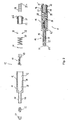
- Figure 1 is a longitudinal sectional view of the first coupling part 10 one Signal coupling according to a development of the present invention in an exploded view (above) and in the assembled state (below).
- Figure 2 is a longitudinal sectional view of the second coupling part 12 of the same signal coupling in exploded view (above) and in the assembled Condition shown (below). Since the first and the second coupling part 10 or 12 are identical in many characteristics, they are common below described, similar parts by the same reference numerals be marked.
- the coupling parts 10 and 12 each have a housing 14 with a sleeve-like Section 16, in which a light-guiding element 18 is axially displaceable is stored.
- the light-conducting elements 18 can against the biasing force a spring 20 in the sleeve-like section 16 of the respective housing 14 be pressed. Instead of by the spring 20, the light-guiding elements 18 is also biased by gas enclosed in the sleeve-like section 16 his.
- the light-guiding elements 18 each consist of an opaque one Sleeve 22 and a transparent core received therein 24th
- the light-guiding element 18 of the first coupling part has a sleeve-like Spherical concave end surface 26 facing away from housing section 16 (FIG 1) and the light-guiding element 18 of the second coupling part 12 a spherically convex end face 26 '( Figure 2), the radius of curvature of which the spherically concave end face 26 matches.
- the spherical concave end face 26 and the spherically convex end face 26 ' are not only formed in the transparent core 24, but are in the axial end of the respective sleeve 22 of the light-guiding element 18 continued continuously.
- the spherical end face 26 or 26 'of the first or second coupling part 10 and 12 thus has a section formed by the transparent core 24 26a and 26'a and a section 26b formed by the sleeve 22 or 26'b.
- the sections 26b and 26'b are ring-shaped spherical cutouts. Such a spherical section is also in the present document referred to as a "spherical surface".
- Guide grooves 27 are formed in the sleeves 22 and guide pins 28 intervention.
- the displacement movement of the light-guiding elements 18 becomes limited in that one of the ends of the guide groove 27 on the guide pin 28 triggers.
- the interior of the sleeve-like housing section 16 consists of two cylindrical Sections, an inner section 30 and another outer section 32, the diameter of which is larger than that of the inside lying section 30. Between the cylindrical interior sections 30 and 32, a shoulder 34 is formed in the housing inner wall. In the outer interior portion 32 are the light-guiding element 18 and the spring 20, which is at one end on the light-guiding element 18, with the the other end is supported on a metal ring 36, which in turn on the paragraph 34th rests.
- the inner clutch section 30 is located at the first coupling part 10 a transmitting device 38 (FIG. 1) and a receiving device in the second coupling part 40 ( Figure 2). Both the transmitter 38 and the Receiving device 40 have a ground connection 42, which with the sleeve-like Section 16 of the housing 14 is soldered, and a signal connection 44th
- the housing 14 has at its 18 facing away from the light-guiding element End a hollow connector bolt 46 with a ground connection portion 48, a signal connection section 50 and an interposed insulation piece 52 that electrically isolates sections 48 and 50 from one another.
- the Signal connection 44 is guided through the cavity in the connection bolt 46 and soldered to the signal connector 50.
- the inner interior portion 30 and the cavity of the connecting bolt 46 are filled with potting compound, which is shown by hatching in Figures 1 and 2.
- an external thread 54 is formed, with which the coupling part 10 or 12 is in a ground potential Socket can be screwed into a contact carrier.
- the first coupling part 10 and the second coupling part 12 are in coupled state shown.
- the end faces 26 and 26 'of the respective light-guiding element 18 pressed against each other, so that optical Signals from the transmitter 38 in the transparent core 24 of the light-conducting element 18 of the first coupling part 10 are fed, through the end faces 26 and 26 'into the transparent core 22 of the light-guiding Element 18 of the second coupling part 12 transferred and from the Receiving device 40 can be detected.
- the opaque form Sleeves 22 of the light-guiding elements 18 are shielded from daylight Light tunnel, the transmitter 38 and the receiver 40 combines.
- the coupling parts can something moving towards and away from each other without the function the signal coupling would be affected.
- Figure 4 are, for example Coupling parts 10 and 12 of Figure 3 moved slightly towards each other without the position of the light-conducting elements 18 would have changed relative to one another, so that the light transmission remains unaffected.
- the signal coupling shown thus allows a certain tolerance in the relative arrangement of the two Coupling parts 10 and 12 in the coupling direction, i.e. along the optical Axes of the light-guiding elements 18 formed by the central axis thereof becomes.
- the end faces 26 and 26 'loaded with spring pressure act to offset the optical axes of the light-guiding elements 18, i.e. they help align the two coupling parts and the maintain aligned position.
- the two coupling parts 10 and 12 are also coupled Condition shown. Unlike in Figures 3 and 4, here are the coupling parts 10 and 12, however, not arranged on a line, but tilted against each other. This means that the optical axes of the light-guiding elements 18, which each coincide with the axis of symmetry of the transparent core 24, stand at an angle to each other. Because of their spherical shape the end faces 26 and 26 'nevertheless lie against one another without gaps, so that the attenuation of the light as it passes through the end faces 26 and 26 ' keeps within limits. So the signal coupling can be bent to a certain degree, without affecting their function. This is a huge advantage over Usually used flat end faces, which in such a Tilt would be lifted from each other, so that the light transmission from one coupling part would be strongly damped on the other.
- the signal coupling in its maximally buckled position, in which the coupling parts are tilted against each other by 11 °.
- daylight would enter the light tunnel and the optical signal distort.
- the critical angle at which daylight enters the light tunnel would depend on the ratio of the wall thickness of the opaque Sleeves in the area of the end faces 26 and 26 'to the radius of curvature End faces 26, 26 '.
- the wall thickness is opaque sleeve 22 of the first coupling part in the region of the end face 26 less than that of the opaque sleeve 22 of the second coupling part 12, and thus decisive for the determination of the critical angle. It is approximately 1/5 of the radius of curvature of the spherical end faces 26 and 26 '.
- the two coupling parts touch 10, 12 with their spherical end face sections formed by the respective sleeve 22 26b or 26'b. Therefore, 22 additionally electrical signals between the two coupling parts 10 and 12 are transmitted if they are designed to be electrically conductive.
- the end face sections 26b and 26'b are then preferably gold-plated.
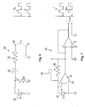
- FIG. 6 shows a functional sketch of the transmission device 38.
- an input voltage V in present between the ground connection 42 and the signal connection 44 is scaled via a resistor 56 and applied to a light-emitting diode 62 via a high pass consisting of a capacitor 58 and a resistor 60, which emits light corresponding to the applied voltage
- the relationship between the applied voltage V in and the radiation power S of the light-emitting diode 62 is shown schematically in a diagram in the right part of FIG. 6, the abscissa showing the time and the ordinate indicating the input voltage V in and the radiation power S in undetermined units.
- FIG. 7 shows a functional sketch of the receiving device 40.
- the receiving device 40 includes a photodiode 64 which generates a voltage as a function of the intensity of the incident light. This is suitably amplified in a first circuit section with the aid of an operational amplifier 66, a resistor 68 and a capacitor 70 and inverted to an output voltage V out with the aid of a further operational amplifier 72.
- the relationship between the received radiation power S '(which multiplied by an attenuation factor corresponds to the radiation power emitted by the LED 62) and the output signal V out of the receiving device 40 is shown schematically in a diagram in the right part of FIG Ordinate shows the received radiation power S 'and the output voltage V ou t in indefinite units.
- the transmitting device 38 and the receiving device 40 are designed such that the output signal V out of the receiving device 40 corresponds to the input voltage V in despite possible attenuation of the transmitted optical signal. Thus, even if the optical signal transmitted between the coupling parts 10 and 12 is subjected to a certain attenuation, the effectively transmitted electrical signal V out is not attenuated compared to the original signal V in .
- the electrical input signal V in can be, for example, an electrical high-frequency signal which is conducted via a coaxial cable within two vehicles and is only converted into an optical signal by means of the transmitting device 38 to pass the signal coupling.
- the signal coupling with the active elements 38 and 40 is also used, for example, when optical signals are already being transmitted in the vehicles by optical fibers. These are then first converted into an electrical signal in the first coupling part 10, which is then applied to the transmitting device 38.
- the output signal V out of the receiving device 40 is then again converted into an optical signal in the second coupling part and fed into a further optical waveguide.
- Figure 8 is a section of a line coupling for use in combination with an automatic rail vehicle coupling in sectional view shown.
- An automatic rail vehicle clutch is used when the train parts have to be coupled and uncoupled more often. Then it is associated cable coupling designed so that its electrical and optical Contacts for automatic coupling of the train parts also automatically are also coupled.
- the cable coupling comprises two contact carriers 74 and 76, in which in addition a series of electrical contacts (not shown) also those described above Coupling parts 10 and 12 of the signal coupling are used.
- the Coupling parts 10 and 12 are with the thread 54 of the connecting bolt 46 screwed into the front of the contact carriers 74 and 76, which causes the thread 54 is connected to ground potential.
- Signal contact section 50 of the first coupling part 10 with a schematic illustrated first signal processing unit 78 and the signal connection section 50 of the second coupling part 12 with a schematic shown second signal processing unit 80 electrically in contact.
- the coupling parts 10 and 12 can be very easily installed and removed are. This is a big advantage over conventional optical signal couplings, whose coupling parts are connected to optical fibers and that only with great difficulty, especially not from the front of the contact carrier 74 or 76 ago can be installed or exchanged.
- the first signal processing unit 78 via a coaxial cable 82 electrical signals and via an optical fiber 84 optical signals supplied.
- the optical signals of the optical waveguide 84 are converted into electrical signals in a converter unit 86 and combined with the electrical signals from the electrical.
- Line 82 one Control unit 88 supplied.
- the control unit 88 has a microprocessor (not shown) for this purpose which is an industrial PC or a so-called field programmable Gate Array (FPGA).
- An FPGA has compared to conventional microprocessors the advantage that it can process several commands at the same time, than is capable of real multitasking.
- the control unit 88 is also connected to a data line 90 via which are fed further information on signal processing. For example can be signaled via data line 90 that already transmitted Signals have arrived incomplete and have to be sent again.
- the conversion of the electrical multiplex signals into optical signals by the Transmitter 38 and its transmission from the first coupling part 10 the second coupling part 12 take place as described above. From the signal connection 50 of the second coupling part 12 arrive in the receiving device 40 generated electrical signals in a control unit 92 of the second signal processing unit 80. The Multiplex signals broken down into individual signals. The originally about the electrical Line 82 received signals are through an electrical line 94 forwarded. Those originally received via the optical fiber 84 Signals are converted back into optical signals in a converter unit 96 and fed into an optical fiber 98.
- Signals from the control unit can be transmitted via a further data line 100 92 forwarded, for example error messages if signals are faulty were received.
- the control unit 92 also contains one Industrial PC or an FPGA (not shown).
- the signal processing units 78 and 80 can also be in the housing 14 of the Coupling parts 10 and 12 are housed. Furthermore, the signal processing units 78 and 80 each with a transmitting coupling part (Similar to the first coupling part 10) and a receivable coupling part (Similar to the second coupling part 12). Then signals can transfer from both sides of the coupling to the other side and the signal processing units 78 and 80 can be either way communicate with each other.
- the coupling parts 10 and 12 cannot only be as shown in FIG. 8 in special contact carriers, but also directly in the coupling heads of one mechanical rail vehicle coupling, for example an automatic one Middle buffer coupling can be arranged (not shown).
- an automatic one Middle buffer coupling can be arranged (not shown).
Landscapes
- Engineering & Computer Science (AREA)
- Mechanical Engineering (AREA)
- Optical Couplings Of Light Guides (AREA)
- Optical Communication System (AREA)
- Semiconductor Lasers (AREA)
- Mutual Connection Of Rods And Tubes (AREA)
- Light Receiving Elements (AREA)
- Mechanical Coupling Of Light Guides (AREA)
- Pivots And Pivotal Connections (AREA)
- Led Device Packages (AREA)
- Photo Coupler, Interrupter, Optical-To-Optical Conversion Devices (AREA)
Abstract
Description
- Fig.1
- eine Schnittdarstellung eines ersten Kupplungsteiles einer Signalkupplung in Explosionsdarstellung (oben) und im zusammengesetzten Zustand (unten),
- Fig.2
- eine Schnittdarstellung eines zweiten Kupplungsteiles einer Signalkupplung in Explosionsdarstellung (oben) und im zusammengesetzten Zustand (unten),
- Fig.3
- eine Schnittdarstellung der Kupplungsteile von Figuren 1 und 2 im gekuppelten Zustand,
- Fig.4
- die gekuppelten Kupplungsteile von Figur 3, deren Abstand in Richtung der optischen Achse verkürzt ist,
- Fig.5
- die gekuppelten Kupplungsteile von Figur 3, deren optische Achsen gegeneinander verkippt sind,
- Fig.6
- eine Funktionsskizze einer Sendeeinrichtung des ersten Kupplungsteiles,
- Fig.7
- eine Funktionsskizze einer Empfangseinrichtung des zweiten Kupplungsteiles und
- Fig.8
- eine Schnittansicht eines Abschnitts einer Leitungskupplung für Schienenfahrzeuge mit zwei Kontaktträgern, in die jeweils ein Kupplungsteil der Signalkupplung eingesetzt ist.
- 10
- erstes Kupplungsteil
- 12
- zweites Kupplungsteil
- 14
- Gehäuse
- 16
- hülsenartiger Gehäuseabschnitt
- 18
- lichtleitendes Element
- 20
- Feder
- 22
- lichtundurchlässige Hülse
- 24
- transparenter Kern
- 26, 26'
- sphärische Stirnfläche
- 27
- Führungsnut
- 28
- Führungsbolzen
- 30
- innerer Innenraumabschnitt
- 32
- äußerer Innenraumabschnitt
- 34
- Absatz
- 36
- Metallring
- 38
- Sendeeinheit
- 40
- Empfangseinheit
- 42
- Masseanschluss
- 44
- Signalanschluss
- 46
- Anschlussbolzen
- 48
- Masseanschlussabschnitt
- 50
- Signalanschlussabschnitt
- 52
- Isolierungsstück
- 54
- Außengewinde
- 56
- Widerstand
- 58
- Kondensator
- 60
- Widerstand
- 62
- LED
- 64
- Fotodiode
- 66
- Operationsverstärker
- 68
- Widerstand
- 70
- Kondensator
- 72
- Operationsverstärker
- 74
- Kontaktträger
- 76
- Kontaktträger
- 78
- Signalverarbeitungseinheit
- 80
- Signalverarbeitungseinheit
- 82
- elektrische Signalleitung
- 84
- Lichtwellenleiter
- 86
- Signalwandler
- 88
- Steuerungseinheit
- 90
- Datenleitung
- 92
- Steuerungseinheit
- 94
- elektrische Signalleitung
- 96
- Signalwandler
- 98
- Lichtwellenleiter
- 100
- Datenleitung
Claims (19)
- Optische Signalkupplung für zwei miteinander gekuppelte Fahrzeuge, insbesondere miteinander gekuppelte Schienenfahrzeuge, mit einem an dem einen Fahrzeug festgelegten ersten Kupplungsteil (10) und einem an dem anderen Fahrzeug festgelegten zweiten Kupplungsteil (12), zwischen denen optische Signale übertragen werden, dadurch gekennzeichnet, dass das erste Kupplungsteil (10) eine Sendeeinrichtung (38) beinhaltet, die die zu übertragenden optischen Signale erzeugt, und das zweite Kupplungsteil (12) eine Empfangseinrichtung (40) beinhaltet, die die übertragenen optischen Signale detektiert.
- Optische Signalkupplung nach Anspruch 1, dadurch gekennzeichnet, dass das erste Kupplungsteil (10) einen Mikroprozessor umfasst, der die Erzeugung der Signale in der Sendeeinrichtung (38) steuert.
- Optische Signalkupplung nach Anspruch 1 oder 2, dadurch gekennzeichnet, dass das zweite Kupplungsteil (12) einen Mikroprozessor umfasst, der die in der Empfangseinrichtung (40) detektierten Signale verarbeitet.
- Optische Signalvorrichtung nach Anspruch 2 und 3, dadurch gekennzeichnet, dass der Mikroprozessor des ersten Kupplungsteiles (10) so programmiert ist, dass er mehrere individuelle Signale zu Multiplexsignalen vereint und der Mikroprozessor des zweiten Kupplungsteiles (12) so programmiert ist, dass er Multiplexsignale in mehrere individuelle Signale zerlegt.
- Optische Signalkupplung nach einem der vorhergehenden Ansprüche, dadurch gekennzeichnet, dass die Sendeeinrichtung (38) mindestens eine LED (62) zur Erzeugung der optischen Signale hat.
- Optische Signalkupplung nach einem der vorhergehenden Ansprüche, dadurch gekennzeichnet, dass die Empfangseinrichtung (40) eine Fotodiode (64) zum Detektierten der optischen Signale hat.
- Optische Signalkupplung nach einem der vorhergehenden Ansprüche, dadurch gekennzeichnet, dass im ersten und zweiten Kupplungsteil (10, 12) jeweils ein lichtleitendes Element (18) gehalten ist, von denen eines eine sphärisch konkave Stirnfläche (26) und das andere eine mit gleichem Krümmungsradius sphärisch konvexe Stirnfläche (26') hat und von denen mindestens eines derart elastisch vorgespannt ist, dass die lichtleitenden Elemente (18) mit ihren Stirnflächen (26, 26') aneinander gedrückt werden, wenn die zwei Fahrzeuge miteinander gekuppelt sind.
- Optische Signalkupplung nach Anspruch 7, dadurch gekennzeichnet, dass die lichtleitenden Elemente (18) jeweils aus einer lichtundurchlässigen Hülse (22) und einem darin aufgenommenen transparenten Kern (24) bestehen.
- Optische Signalkupplung nach Anspruch 8, dadurch gekennzeichnet, dass die Wanddicke der Hülse (22) im Bereich der Stirnfläche (26, 26') mindestens 1110, vorzugsweise mindestens 1/5 des Krümmungsradius der Stirnflächen (26, 26') beträgt.
- Optische Signalkupplung nach Anspruch 8 oder 9, dadurch gekennzeichnet, dass die lichtundurchlässigen Hülsen (22) elektrisch leitend sind und dass beim Aneinanderdrücken der Stirnflächen (26, 26b, 26', 26'b) der lichtleitenden Elemente (18) des ersten und zweiten Kupplungsteils (10,12) ein elektrischer Kontakt zwischen den zugehörigen Hülsen (22) hergestellt wird, über den elektrische Signale von einem Kupplungsteil (10, 12) auf das andere Kupplungsteil (12, 10) übertragbar sind.
- Optische Signalkupplung nach Anspruch 10, dadurch gekennzeichnet, dass der Abschnitt (26b, 26'b) einer jeden Hülse (22), der Teil einer Stirnfläche (26, 26') ist, hartvergoldet ist.
- Optische Signalkupplung nach Anspruch 10 oder 11, dadurch gekennzeichnet, dass zumindest ein Teil der Signale, die als optische Signale zwischen den Kupplungsteilen (10, 12) übertragen werden, zusätzlich als elektrische Signale über die Hülsen (22) der beiden Kupplungsteile (10, 12) übertragen werden.
- Optische Signalkupplung nach einem der Ansprüche 7 bis 12, dadurch gekennzeichnet, dass das erste und das zweite Kupplungsteil (10, 12) ein Gehäuse (14) haben, an dessen einem axialen Ende ein hülsenartiger Abschnitt (16) ausgebildet ist, in dem das lichtleitende Element (18) axial verschiebbar gelagert und in Richtung auf dieses eine axiale Ende elastisch vorgespannt ist, und an dessen anderem Ende ein Anschlussbolzen (46) ausgebildet ist, der zum Einsetzen in einen Kontaktträger (74, 76) bestimmt ist.
- Optische Signalkupplung nach einem der Ansprüche 10 bis 12 und Anspruch 13, dadurch gekennzeichnet, dass zwischen der Hülse (22) des lichtleitenden Elementes (18) und dem hülsenartigen Abschnitt (16) des Gehäuses (14) eines jeden Kupplungsteiles (10, 12) ein elektrischer Schleifkontakt besteht, über den elektrische Signale zwischen dem hülsenartigen Abschnitt (16) und der Hülse (22) übertragbar sind.
- Optische Signalkupplung nach Anspruch 13 oder 14, dadurch. gekennzeichnet, dass der Anschlussbolzen (46) aus zwei gegeneinander isolierten Abschnitten (48, 50) besteht, von denen der eine mit dem Massepotential und der andere mit einer elektrischen Signalleitung verbunden ist, wenn der Anschlussbolzen (46) in den Kontaktträger (74, 76) eingesetzt ist.
- Optische Signalkupplung nach einem der vorhergehenden Ansprüche, dadurch gekennzeichnet, dass die Kupplungsteile (10, 12) in den Kupplungsköpfen einer mechanischen Kupplung für Schienenfahrzeuge angeordnet sind.
- Leitungskupplung zum Verbinden von Leitungen zweier miteinander kuppelbarer Schienenfahrzeuge, mit zwei Kontaktträgern (74, 76), von denen jeweils einer an jedem Schienenfahrzeug befestigt ist, dadurch gekennzeichnet, dass im einen Kontaktträger (74) mindestens ein Signalkupplungsteil (10) mit Sendeeinrichtung (38) und im anderen Kontaktträger (76) mindestens ein Signalkupplungsteil (12) mit Empfangseinrichtung (40) angeordnet ist, die zusammen eine optische Signalkupplung nach einem der Ansprüche 1 bis 11 bilden.
- Leitungskupplung nach Anspruch 17, dadurch gekennzeichnet, dass in jedem der Kontaktträger (74, 76) jeweils sowohl ein Signalkupplungsteil (10) mit Sendeeinrichtung (38) als auch ein Signalkupplungsteil (12) mit Empfangseinrichtung (40) angeordnet ist, die zusammen zwei optische Signalkupplungen nach einem der Ansprüche 1 bis 11 bilden.
- Leitungskupplung nach Anspruch 18, dadurch gekennzeichnet, dass die Sendeeinrichtung (38) und die Empfangseinrichtung (40) der Kupplungsteile (10, 12) eines jeden Kontaktträgers (74, 76) mit einem gemeinsamen Mikroprozessor verbunden sind, der die Erzeugung der Signale in der Sendeeinrichtung (38) steuert und die in der Empfangseinrichtung (40) detektierten Signale verarbeitet.
Applications Claiming Priority (2)
| Application Number | Priority Date | Filing Date | Title |
|---|---|---|---|
| DE10310134 | 2003-03-07 | ||
| DE10310134A DE10310134B3 (de) | 2003-03-07 | 2003-03-07 | Optische Signalkupplung |
Publications (3)
| Publication Number | Publication Date |
|---|---|
| EP1454808A1 true EP1454808A1 (de) | 2004-09-08 |
| EP1454808B1 EP1454808B1 (de) | 2008-09-24 |
| EP1454808B2 EP1454808B2 (de) | 2011-04-06 |
Family
ID=32797880
Family Applications (1)
| Application Number | Title | Priority Date | Filing Date |
|---|---|---|---|
| EP03010283A Expired - Lifetime EP1454808B2 (de) | 2003-03-07 | 2003-05-07 | Optische Signalkupplung |
Country Status (9)
| Country | Link |
|---|---|
| US (1) | US7270486B2 (de) |
| EP (1) | EP1454808B2 (de) |
| JP (1) | JP3997200B2 (de) |
| CN (1) | CN1526588B (de) |
| AT (1) | ATE409151T1 (de) |
| AU (1) | AU2003255194B2 (de) |
| CA (1) | CA2447176C (de) |
| DE (2) | DE10310134B3 (de) |
| ES (1) | ES2316669T5 (de) |
Cited By (1)
| Publication number | Priority date | Publication date | Assignee | Title |
|---|---|---|---|---|
| WO2016162469A1 (de) * | 2015-04-10 | 2016-10-13 | Voith Patent Gmbh | Vorrichtung zum übertragen von daten und/oder signalen |
Families Citing this family (14)
| Publication number | Priority date | Publication date | Assignee | Title |
|---|---|---|---|---|
| JP2005333019A (ja) * | 2004-05-20 | 2005-12-02 | Sony Corp | 光コネクタおよび光通信装置 |
| JP2009500237A (ja) * | 2005-07-07 | 2009-01-08 | ジオフォーカス リミテッド ライアビリティ カンパニー | 無接点のデータ通信連結 |
| CA2646673A1 (en) * | 2006-01-06 | 2007-07-12 | Geofocus Llc | Contactless data communications coupler |
| FR3031793B1 (fr) * | 2015-01-15 | 2017-01-27 | Valeo Iluminacion Sa | Dispositif lumineux de vehicule dans lequel un guide de lumiere supporte un autre guide de lumiere |
| EP3379222B1 (de) | 2017-03-22 | 2020-12-30 | Methode Electronics Malta Ltd. | Auf magnetoelastik basierte sensoranordnung |
| FR3067419B1 (fr) * | 2017-06-09 | 2019-07-19 | Sebastien Mallinjoud | Dispositif de liaison mecanique et de transmission optique et/ou electrique et/ou fluidique |
| US10670479B2 (en) | 2018-02-27 | 2020-06-02 | Methode Electronics, Inc. | Towing systems and methods using magnetic field sensing |
| US11084342B2 (en) | 2018-02-27 | 2021-08-10 | Methode Electronics, Inc. | Towing systems and methods using magnetic field sensing |
| US11491832B2 (en) | 2018-02-27 | 2022-11-08 | Methode Electronics, Inc. | Towing systems and methods using magnetic field sensing |
| US11221262B2 (en) | 2018-02-27 | 2022-01-11 | Methode Electronics, Inc. | Towing systems and methods using magnetic field sensing |
| US11135882B2 (en) | 2018-02-27 | 2021-10-05 | Methode Electronics, Inc. | Towing systems and methods using magnetic field sensing |
| US11014417B2 (en) | 2018-02-27 | 2021-05-25 | Methode Electronics, Inc. | Towing systems and methods using magnetic field sensing |
| CN115427263B (zh) * | 2020-04-27 | 2024-05-28 | 住友电气工业株式会社 | 车载布线系统及车载布线系统的构建方法 |
| CN112882163B (zh) * | 2021-01-19 | 2023-05-05 | 武汉电信器件有限公司 | 一种光模块以及光电连接器 |
Citations (7)
| Publication number | Priority date | Publication date | Assignee | Title |
|---|---|---|---|---|
| US3809908A (en) * | 1973-06-29 | 1974-05-07 | Itt | Electro-optical transmission line |
| DE2922937C2 (de) | 1979-06-01 | 1981-07-02 | Fabeg Gmbh, 7518 Bretten | Kabelkupplung zum selbsttätigen Durchkuppeln elektrischer Heiz- und/oder Steuerstromleitungen sowie von Lichtleitern zur optischen Befehlsübertragung, insbesondere für Bahnfahrzeuge |
| DE2854962C2 (de) | 1978-12-20 | 1986-09-04 | Scharfenbergkupplung Gmbh, 3320 Salzgitter | Mittelpufferkupplung für Schienenfahrzeuge mit Kabelkupplungen |
| EP0395607A1 (de) * | 1989-04-25 | 1990-10-31 | Telefonaktiebolaget L M Ericsson | Kontaktanordnung |
| FR2691264A1 (fr) * | 1992-05-12 | 1993-11-19 | Aerospatiale | Système de raccordement de liaisons optiques à des liaisons électriques. |
| US5917632A (en) * | 1995-02-23 | 1999-06-29 | Vehicle Enhancement Systems, Inc. | Data communications coupler and lens for tractor/trailer |
| DE10052020A1 (de) | 2000-10-20 | 2002-05-08 | Knorr Bremse Systeme | Steckverbindung |
Family Cites Families (10)
| Publication number | Priority date | Publication date | Assignee | Title |
|---|---|---|---|---|
| DE3640099A1 (de) † | 1986-11-24 | 1988-06-01 | Diehl Gmbh & Co | Baugruppenanordnung |
| US5093879A (en) † | 1990-06-22 | 1992-03-03 | International Business Machines Corporation | Electro-optical connectors |
| DE4216065C2 (de) | 1992-05-15 | 2002-01-03 | Daimlerchrysler Aerospace Ag | Verfahren zur Analog/Digitalwandlung von Mikrowellensignalen |
| AU4639393A (en) * | 1992-06-16 | 1994-01-04 | Dill Systems Corp. | Magnetic circuits for communicating data |
| ZA938323B (en) * | 1992-11-24 | 1994-08-01 | Qualcomm Inc | Tractor-trailer electronic transmission path |
| US5450226A (en) * | 1993-01-29 | 1995-09-12 | Morrison Knudsen Corporation | Inter-car optical coupling |
| US5475215A (en) * | 1994-01-03 | 1995-12-12 | Hsu; Winston | Optical communicating apparatus for communcating optical signals between electronic circuts |
| US5857042A (en) * | 1997-04-29 | 1999-01-05 | Mcgill University | Optical interconnection arrangements |
| DE10032542B4 (de) † | 2000-07-05 | 2007-09-06 | Schleifring Und Apparatebau Gmbh | Aktiver optischer Drehübertrager |
| DE10310148B4 (de) * | 2003-03-07 | 2005-03-03 | Era-Contact Gmbh | Lichtleiterkupplung |
-
2003
- 2003-03-07 DE DE10310134A patent/DE10310134B3/de not_active Withdrawn - After Issue
- 2003-05-07 EP EP03010283A patent/EP1454808B2/de not_active Expired - Lifetime
- 2003-05-07 ES ES03010283T patent/ES2316669T5/es not_active Expired - Lifetime
- 2003-05-07 AT AT03010283T patent/ATE409151T1/de active
- 2003-05-07 DE DE50310539T patent/DE50310539D1/de not_active Expired - Lifetime
- 2003-08-13 CN CN031278833A patent/CN1526588B/zh not_active Expired - Fee Related
- 2003-10-20 AU AU2003255194A patent/AU2003255194B2/en not_active Ceased
- 2003-10-27 US US10/694,072 patent/US7270486B2/en not_active Expired - Fee Related
- 2003-10-28 CA CA002447176A patent/CA2447176C/en not_active Expired - Fee Related
- 2003-12-19 JP JP2003423377A patent/JP3997200B2/ja not_active Expired - Fee Related
Patent Citations (7)
| Publication number | Priority date | Publication date | Assignee | Title |
|---|---|---|---|---|
| US3809908A (en) * | 1973-06-29 | 1974-05-07 | Itt | Electro-optical transmission line |
| DE2854962C2 (de) | 1978-12-20 | 1986-09-04 | Scharfenbergkupplung Gmbh, 3320 Salzgitter | Mittelpufferkupplung für Schienenfahrzeuge mit Kabelkupplungen |
| DE2922937C2 (de) | 1979-06-01 | 1981-07-02 | Fabeg Gmbh, 7518 Bretten | Kabelkupplung zum selbsttätigen Durchkuppeln elektrischer Heiz- und/oder Steuerstromleitungen sowie von Lichtleitern zur optischen Befehlsübertragung, insbesondere für Bahnfahrzeuge |
| EP0395607A1 (de) * | 1989-04-25 | 1990-10-31 | Telefonaktiebolaget L M Ericsson | Kontaktanordnung |
| FR2691264A1 (fr) * | 1992-05-12 | 1993-11-19 | Aerospatiale | Système de raccordement de liaisons optiques à des liaisons électriques. |
| US5917632A (en) * | 1995-02-23 | 1999-06-29 | Vehicle Enhancement Systems, Inc. | Data communications coupler and lens for tractor/trailer |
| DE10052020A1 (de) | 2000-10-20 | 2002-05-08 | Knorr Bremse Systeme | Steckverbindung |
Cited By (3)
| Publication number | Priority date | Publication date | Assignee | Title |
|---|---|---|---|---|
| WO2016162469A1 (de) * | 2015-04-10 | 2016-10-13 | Voith Patent Gmbh | Vorrichtung zum übertragen von daten und/oder signalen |
| CN107428347A (zh) * | 2015-04-10 | 2017-12-01 | 沃依特专利有限责任公司 | 用于传送数据和/或信号的设备 |
| US10683020B2 (en) | 2015-04-10 | 2020-06-16 | Voith Patent Gmbh | Device for transmitting data and/or signals |
Also Published As
| Publication number | Publication date |
|---|---|
| EP1454808B1 (de) | 2008-09-24 |
| US7270486B2 (en) | 2007-09-18 |
| HK1068315A1 (zh) | 2005-04-29 |
| AU2003255194B2 (en) | 2009-10-01 |
| JP3997200B2 (ja) | 2007-10-24 |
| ES2316669T5 (es) | 2011-07-21 |
| DE50310539D1 (de) | 2008-11-06 |
| ES2316669T3 (es) | 2009-04-16 |
| DE10310134B3 (de) | 2004-09-30 |
| CA2447176C (en) | 2008-12-30 |
| JP2004268905A (ja) | 2004-09-30 |
| US20040175068A1 (en) | 2004-09-09 |
| ATE409151T1 (de) | 2008-10-15 |
| AU2003255194A1 (en) | 2004-09-23 |
| CA2447176A1 (en) | 2004-09-07 |
| CN1526588A (zh) | 2004-09-08 |
| CN1526588B (zh) | 2010-05-05 |
| EP1454808B2 (de) | 2011-04-06 |
Similar Documents
| Publication | Publication Date | Title |
|---|---|---|
| EP1454808B1 (de) | Optische Signalkupplung | |
| EP1455207B1 (de) | Lichtleiterkupplung | |
| EP2616304B1 (de) | Elektrokupplung für eisenbahnen | |
| EP2334534B1 (de) | Mittelpufferkupplung für schienengebundene fahrzeuge | |
| EP0410143A2 (de) | Optelektrische Sende- und Empfangsvorrichtung | |
| EP0982215B1 (de) | Anordnung für Schienenfahrzeuge, bestehend aus einer Mittelpufferkupplung und einer daran längsverschiebbar angeordneten elektrischen Kabelkupplung | |
| EP3280629A1 (de) | Vorrichtung zum übertragen von daten und/oder signalen | |
| DE4437976C2 (de) | Kupplungsvorrichtung für Lichtwellenleiter | |
| DE2741585B2 (de) | Einschubsteckverbindung fur Lichtwellenleiter | |
| EP0862820A1 (de) | Vorrichtung zur optischen signalübertragung | |
| DE4414862C2 (de) | Lichtwellenleiter-Steckverbinder mit Überwachungseinrichtung | |
| EP1869805B1 (de) | Elektrooptische kopplungseinrichtung | |
| WO2016015963A1 (de) | Elektrokontaktkupplung mit schnittstelle | |
| EP0896234A2 (de) | Linsenkopplung für Glasfaserkabel | |
| WO2014082789A1 (de) | Verriegelungsvorrichtung für einen fahrzeugsitz, anordnung von mindestens zwei verriegelungsvorrichtungen und fahrzeugsitz | |
| WO2000016142A2 (de) | Mehrkanalige optische kopplungseinrichtung | |
| DE19952420C2 (de) | Verfahren und Vorrichtung zur Durchgängigkeitsprüfung für einen Lichtwellenleiter | |
| DE9319378U1 (de) | Kombinierte Sende- und Empfangsstation für die optische Nachrichtenübertragung | |
| EP0990914A2 (de) | Prüfeinrichtung für mit Lichtwellenleitern bestückte Stecker | |
| DE202005005767U1 (de) | Elektrooptische Kopplungseinrichtung | |
| HK1068415B (en) | Light conductor coupling | |
| WO2006029877A1 (de) | Medizinisches laserbehandlungsgerät | |
| EP0092217A2 (de) | Lichtwellenleitersteckvorrichtung insbesondere für die Einschubtechnik | |
| EP1037079A2 (de) | Steckverbinder für Lichtleiter |
Legal Events
| Date | Code | Title | Description |
|---|---|---|---|
| PUAI | Public reference made under article 153(3) epc to a published international application that has entered the european phase |
Free format text: ORIGINAL CODE: 0009012 |
|
| AK | Designated contracting states |
Kind code of ref document: A1 Designated state(s): AT BE BG CH CY CZ DE DK EE ES FI FR GB GR HU IE IT LI LU MC NL PT RO SE SI SK TR |
|
| AX | Request for extension of the european patent |
Extension state: AL LT LV MK |
|
| 17P | Request for examination filed |
Effective date: 20041203 |
|
| AKX | Designation fees paid |
Designated state(s): AT BE BG CH CY CZ DE DK EE ES FI FR GB GR HU IE IT LI LU MC NL PT RO SE SI SK TR |
|
| 17Q | First examination report despatched |
Effective date: 20061107 |
|
| 17Q | First examination report despatched |
Effective date: 20061107 |
|
| GRAP | Despatch of communication of intention to grant a patent |
Free format text: ORIGINAL CODE: EPIDOSNIGR1 |
|
| GRAS | Grant fee paid |
Free format text: ORIGINAL CODE: EPIDOSNIGR3 |
|
| GRAA | (expected) grant |
Free format text: ORIGINAL CODE: 0009210 |
|
| AK | Designated contracting states |
Kind code of ref document: B1 Designated state(s): AT BE BG CH CY CZ DE DK EE ES FI FR GB GR HU IE IT LI LU MC NL PT RO SE SI SK TR |
|
| REG | Reference to a national code |
Ref country code: GB Ref legal event code: FG4D Free format text: NOT ENGLISH |
|
| REG | Reference to a national code |
Ref country code: CH Ref legal event code: EP |
|
| REG | Reference to a national code |
Ref country code: IE Ref legal event code: FG4D Free format text: LANGUAGE OF EP DOCUMENT: GERMAN |
|
| REF | Corresponds to: |
Ref document number: 50310539 Country of ref document: DE Date of ref document: 20081106 Kind code of ref document: P |
|
| REG | Reference to a national code |
Ref country code: SE Ref legal event code: TRGR |
|
| REG | Reference to a national code |
Ref country code: CH Ref legal event code: NV Representative=s name: SCHNEIDER FELDMANN AG PATENT- UND MARKENANWAELTE |
|
| PG25 | Lapsed in a contracting state [announced via postgrant information from national office to epo] |
Ref country code: SI Free format text: LAPSE BECAUSE OF FAILURE TO SUBMIT A TRANSLATION OF THE DESCRIPTION OR TO PAY THE FEE WITHIN THE PRESCRIBED TIME-LIMIT Effective date: 20080924 Ref country code: FI Free format text: LAPSE BECAUSE OF FAILURE TO SUBMIT A TRANSLATION OF THE DESCRIPTION OR TO PAY THE FEE WITHIN THE PRESCRIBED TIME-LIMIT Effective date: 20080924 |
|
| NLV1 | Nl: lapsed or annulled due to failure to fulfill the requirements of art. 29p and 29m of the patents act | ||
| REG | Reference to a national code |
Ref country code: ES Ref legal event code: FG2A Ref document number: 2316669 Country of ref document: ES Kind code of ref document: T3 |
|
| REG | Reference to a national code |
Ref country code: IE Ref legal event code: FD4D |
|
| PG25 | Lapsed in a contracting state [announced via postgrant information from national office to epo] |
Ref country code: BG Free format text: LAPSE BECAUSE OF FAILURE TO SUBMIT A TRANSLATION OF THE DESCRIPTION OR TO PAY THE FEE WITHIN THE PRESCRIBED TIME-LIMIT Effective date: 20081224 |
|
| PG25 | Lapsed in a contracting state [announced via postgrant information from national office to epo] |
Ref country code: NL Free format text: LAPSE BECAUSE OF FAILURE TO SUBMIT A TRANSLATION OF THE DESCRIPTION OR TO PAY THE FEE WITHIN THE PRESCRIBED TIME-LIMIT Effective date: 20080924 Ref country code: PT Free format text: LAPSE BECAUSE OF FAILURE TO SUBMIT A TRANSLATION OF THE DESCRIPTION OR TO PAY THE FEE WITHIN THE PRESCRIBED TIME-LIMIT Effective date: 20090224 Ref country code: SK Free format text: LAPSE BECAUSE OF FAILURE TO SUBMIT A TRANSLATION OF THE DESCRIPTION OR TO PAY THE FEE WITHIN THE PRESCRIBED TIME-LIMIT Effective date: 20080924 Ref country code: RO Free format text: LAPSE BECAUSE OF FAILURE TO SUBMIT A TRANSLATION OF THE DESCRIPTION OR TO PAY THE FEE WITHIN THE PRESCRIBED TIME-LIMIT Effective date: 20080924 |
|
| PLBI | Opposition filed |
Free format text: ORIGINAL CODE: 0009260 |
|
| 26 | Opposition filed |
Opponent name: SCHLEIFRING UND APPARATEBAU GMBH Effective date: 20090618 |
|
| PG25 | Lapsed in a contracting state [announced via postgrant information from national office to epo] |
Ref country code: IE Free format text: LAPSE BECAUSE OF FAILURE TO SUBMIT A TRANSLATION OF THE DESCRIPTION OR TO PAY THE FEE WITHIN THE PRESCRIBED TIME-LIMIT Effective date: 20080924 Ref country code: DK Free format text: LAPSE BECAUSE OF FAILURE TO SUBMIT A TRANSLATION OF THE DESCRIPTION OR TO PAY THE FEE WITHIN THE PRESCRIBED TIME-LIMIT Effective date: 20080924 Ref country code: EE Free format text: LAPSE BECAUSE OF FAILURE TO SUBMIT A TRANSLATION OF THE DESCRIPTION OR TO PAY THE FEE WITHIN THE PRESCRIBED TIME-LIMIT Effective date: 20080924 |
|
| PLAX | Notice of opposition and request to file observation + time limit sent |
Free format text: ORIGINAL CODE: EPIDOSNOBS2 |
|
| BERE | Be: lapsed |
Owner name: ERA-CONTACT G.M.B.H. Effective date: 20090531 |
|
| PLAF | Information modified related to communication of a notice of opposition and request to file observations + time limit |
Free format text: ORIGINAL CODE: EPIDOSCOBS2 |
|
| PG25 | Lapsed in a contracting state [announced via postgrant information from national office to epo] |
Ref country code: MC Free format text: LAPSE BECAUSE OF NON-PAYMENT OF DUE FEES Effective date: 20090531 |
|
| PLBB | Reply of patent proprietor to notice(s) of opposition received |
Free format text: ORIGINAL CODE: EPIDOSNOBS3 |
|
| PG25 | Lapsed in a contracting state [announced via postgrant information from national office to epo] |
Ref country code: BE Free format text: LAPSE BECAUSE OF NON-PAYMENT OF DUE FEES Effective date: 20090531 |
|
| PG25 | Lapsed in a contracting state [announced via postgrant information from national office to epo] |
Ref country code: GR Free format text: LAPSE BECAUSE OF FAILURE TO SUBMIT A TRANSLATION OF THE DESCRIPTION OR TO PAY THE FEE WITHIN THE PRESCRIBED TIME-LIMIT Effective date: 20081225 |
|
| PUAH | Patent maintained in amended form |
Free format text: ORIGINAL CODE: 0009272 |
|
| STAA | Information on the status of an ep patent application or granted ep patent |
Free format text: STATUS: PATENT MAINTAINED AS AMENDED |
|
| 27A | Patent maintained in amended form |
Effective date: 20110406 |
|
| AK | Designated contracting states |
Kind code of ref document: B2 Designated state(s): AT BE BG CH CY CZ DE DK EE ES FI FR GB GR HU IE IT LI LU MC NL PT RO SE SI SK TR |
|
| REG | Reference to a national code |
Ref country code: CH Ref legal event code: AEN Free format text: AUFRECHTERHALTUNG DES PATENTES IN GEAENDERTER FORM |
|
| PG25 | Lapsed in a contracting state [announced via postgrant information from national office to epo] |
Ref country code: LU Free format text: LAPSE BECAUSE OF NON-PAYMENT OF DUE FEES Effective date: 20090507 |
|
| REG | Reference to a national code |
Ref country code: DE Ref legal event code: R102 Ref document number: 50310539 Country of ref document: DE Effective date: 20110406 |
|
| PG25 | Lapsed in a contracting state [announced via postgrant information from national office to epo] |
Ref country code: HU Free format text: LAPSE BECAUSE OF FAILURE TO SUBMIT A TRANSLATION OF THE DESCRIPTION OR TO PAY THE FEE WITHIN THE PRESCRIBED TIME-LIMIT Effective date: 20090325 |
|
| REG | Reference to a national code |
Ref country code: ES Ref legal event code: DC2A Ref document number: 2316669 Country of ref document: ES Kind code of ref document: T5 Effective date: 20110721 |
|
| REG | Reference to a national code |
Ref country code: SE Ref legal event code: RPEO |
|
| PG25 | Lapsed in a contracting state [announced via postgrant information from national office to epo] |
Ref country code: TR Free format text: LAPSE BECAUSE OF FAILURE TO SUBMIT A TRANSLATION OF THE DESCRIPTION OR TO PAY THE FEE WITHIN THE PRESCRIBED TIME-LIMIT Effective date: 20080924 |
|
| PG25 | Lapsed in a contracting state [announced via postgrant information from national office to epo] |
Ref country code: CY Free format text: LAPSE BECAUSE OF FAILURE TO SUBMIT A TRANSLATION OF THE DESCRIPTION OR TO PAY THE FEE WITHIN THE PRESCRIBED TIME-LIMIT Effective date: 20080924 |
|
| PGFP | Annual fee paid to national office [announced via postgrant information from national office to epo] |
Ref country code: ES Payment date: 20120525 Year of fee payment: 10 |
|
| PGFP | Annual fee paid to national office [announced via postgrant information from national office to epo] |
Ref country code: AT Payment date: 20120521 Year of fee payment: 10 |
|
| PGFP | Annual fee paid to national office [announced via postgrant information from national office to epo] |
Ref country code: CH Payment date: 20130522 Year of fee payment: 11 Ref country code: CZ Payment date: 20130426 Year of fee payment: 11 Ref country code: SE Payment date: 20130521 Year of fee payment: 11 Ref country code: DE Payment date: 20130624 Year of fee payment: 11 Ref country code: GB Payment date: 20130522 Year of fee payment: 11 |
|
| PGFP | Annual fee paid to national office [announced via postgrant information from national office to epo] |
Ref country code: FR Payment date: 20130604 Year of fee payment: 11 Ref country code: IT Payment date: 20130525 Year of fee payment: 11 |
|
| PG25 | Lapsed in a contracting state [announced via postgrant information from national office to epo] |
Ref country code: CZ Free format text: LAPSE BECAUSE OF FAILURE TO SUBMIT A TRANSLATION OF THE DESCRIPTION OR TO PAY THE FEE WITHIN THE PRESCRIBED TIME-LIMIT Effective date: 20080924 |
|
| REG | Reference to a national code |
Ref country code: DE Ref legal event code: R119 Ref document number: 50310539 Country of ref document: DE |
|
| REG | Reference to a national code |
Ref country code: CH Ref legal event code: PL |
|
| REG | Reference to a national code |
Ref country code: AT Ref legal event code: MM01 Ref document number: 409151 Country of ref document: AT Kind code of ref document: T Effective date: 20140507 |
|
| GBPC | Gb: european patent ceased through non-payment of renewal fee |
Effective date: 20140507 |
|
| PG25 | Lapsed in a contracting state [announced via postgrant information from national office to epo] |
Ref country code: LI Free format text: LAPSE BECAUSE OF NON-PAYMENT OF DUE FEES Effective date: 20140531 Ref country code: SE Free format text: LAPSE BECAUSE OF NON-PAYMENT OF DUE FEES Effective date: 20140508 Ref country code: CH Free format text: LAPSE BECAUSE OF NON-PAYMENT OF DUE FEES Effective date: 20140531 |
|
| REG | Reference to a national code |
Ref country code: SE Ref legal event code: EUG |
|
| PG25 | Lapsed in a contracting state [announced via postgrant information from national office to epo] |
Ref country code: AT Free format text: LAPSE BECAUSE OF NON-PAYMENT OF DUE FEES Effective date: 20140507 |
|
| REG | Reference to a national code |
Ref country code: FR Ref legal event code: ST Effective date: 20150130 |
|
| REG | Reference to a national code |
Ref country code: DE Ref legal event code: R119 Ref document number: 50310539 Country of ref document: DE Effective date: 20141202 |
|
| PG25 | Lapsed in a contracting state [announced via postgrant information from national office to epo] |
Ref country code: IT Free format text: LAPSE BECAUSE OF NON-PAYMENT OF DUE FEES Effective date: 20140507 Ref country code: DE Free format text: LAPSE BECAUSE OF NON-PAYMENT OF DUE FEES Effective date: 20141202 |
|
| PG25 | Lapsed in a contracting state [announced via postgrant information from national office to epo] |
Ref country code: GB Free format text: LAPSE BECAUSE OF NON-PAYMENT OF DUE FEES Effective date: 20140507 Ref country code: FR Free format text: LAPSE BECAUSE OF NON-PAYMENT OF DUE FEES Effective date: 20140602 |
|
| REG | Reference to a national code |
Ref country code: ES Ref legal event code: FD2A Effective date: 20150731 |
|
| PG25 | Lapsed in a contracting state [announced via postgrant information from national office to epo] |
Ref country code: ES Free format text: LAPSE BECAUSE OF NON-PAYMENT OF DUE FEES Effective date: 20140508 |
|
| PG25 | Lapsed in a contracting state [announced via postgrant information from national office to epo] |
Ref country code: CZ Free format text: THE PATENT HAS BEEN ANNULLED BY A DECISION OF A NATIONAL AUTHORITY Effective date: 20080924 |