EP1454792B1 - Dispositif de phares pour véhicule routier - Google Patents
Dispositif de phares pour véhicule routier Download PDFInfo
- Publication number
- EP1454792B1 EP1454792B1 EP04002640A EP04002640A EP1454792B1 EP 1454792 B1 EP1454792 B1 EP 1454792B1 EP 04002640 A EP04002640 A EP 04002640A EP 04002640 A EP04002640 A EP 04002640A EP 1454792 B1 EP1454792 B1 EP 1454792B1
- Authority
- EP
- European Patent Office
- Prior art keywords
- value
- pitch angle
- headlight
- land vehicle
- height
- Prior art date
- Legal status (The legal status is an assumption and is not a legal conclusion. Google has not performed a legal analysis and makes no representation as to the accuracy of the status listed.)
- Expired - Lifetime
Links
- 230000003287 optical effect Effects 0.000 claims abstract description 29
- 230000000694 effects Effects 0.000 claims abstract description 17
- 230000003044 adaptive effect Effects 0.000 claims description 26
- 238000012935 Averaging Methods 0.000 claims description 6
- 238000013178 mathematical model Methods 0.000 claims description 4
- 238000013528 artificial neural network Methods 0.000 claims description 2
- 230000001133 acceleration Effects 0.000 description 14
- 230000004044 response Effects 0.000 description 8
- 230000001419 dependent effect Effects 0.000 description 4
- 238000001914 filtration Methods 0.000 description 2
- 238000000034 method Methods 0.000 description 2
- 230000002123 temporal effect Effects 0.000 description 2
- 206010038743 Restlessness Diseases 0.000 description 1
- 230000015572 biosynthetic process Effects 0.000 description 1
- 238000001514 detection method Methods 0.000 description 1
- 238000009434 installation Methods 0.000 description 1
- 230000007794 irritation Effects 0.000 description 1
- 230000004043 responsiveness Effects 0.000 description 1
- 239000000725 suspension Substances 0.000 description 1
Images


Classifications
-
- B—PERFORMING OPERATIONS; TRANSPORTING
- B60—VEHICLES IN GENERAL
- B60Q—ARRANGEMENT OF SIGNALLING OR LIGHTING DEVICES, THE MOUNTING OR SUPPORTING THEREOF OR CIRCUITS THEREFOR, FOR VEHICLES IN GENERAL
- B60Q1/00—Arrangement of optical signalling or lighting devices, the mounting or supporting thereof or circuits therefor
- B60Q1/02—Arrangement of optical signalling or lighting devices, the mounting or supporting thereof or circuits therefor the devices being primarily intended to illuminate the way ahead or to illuminate other areas of way or environments
- B60Q1/04—Arrangement of optical signalling or lighting devices, the mounting or supporting thereof or circuits therefor the devices being primarily intended to illuminate the way ahead or to illuminate other areas of way or environments the devices being headlights
- B60Q1/06—Arrangement of optical signalling or lighting devices, the mounting or supporting thereof or circuits therefor the devices being primarily intended to illuminate the way ahead or to illuminate other areas of way or environments the devices being headlights adjustable, e.g. remotely-controlled from inside vehicle
- B60Q1/08—Arrangement of optical signalling or lighting devices, the mounting or supporting thereof or circuits therefor the devices being primarily intended to illuminate the way ahead or to illuminate other areas of way or environments the devices being headlights adjustable, e.g. remotely-controlled from inside vehicle automatically
- B60Q1/10—Arrangement of optical signalling or lighting devices, the mounting or supporting thereof or circuits therefor the devices being primarily intended to illuminate the way ahead or to illuminate other areas of way or environments the devices being headlights adjustable, e.g. remotely-controlled from inside vehicle automatically due to vehicle inclination, e.g. due to load distribution
-
- B—PERFORMING OPERATIONS; TRANSPORTING
- B60—VEHICLES IN GENERAL
- B60Q—ARRANGEMENT OF SIGNALLING OR LIGHTING DEVICES, THE MOUNTING OR SUPPORTING THEREOF OR CIRCUITS THEREFOR, FOR VEHICLES IN GENERAL
- B60Q2300/00—Indexing codes for automatically adjustable headlamps or automatically dimmable headlamps
- B60Q2300/10—Indexing codes relating to particular vehicle conditions
- B60Q2300/11—Linear movements of the vehicle
- B60Q2300/114—Vehicle acceleration or deceleration
-
- B—PERFORMING OPERATIONS; TRANSPORTING
- B60—VEHICLES IN GENERAL
- B60Q—ARRANGEMENT OF SIGNALLING OR LIGHTING DEVICES, THE MOUNTING OR SUPPORTING THEREOF OR CIRCUITS THEREFOR, FOR VEHICLES IN GENERAL
- B60Q2300/00—Indexing codes for automatically adjustable headlamps or automatically dimmable headlamps
- B60Q2300/10—Indexing codes relating to particular vehicle conditions
- B60Q2300/13—Attitude of the vehicle body
- B60Q2300/132—Pitch
Definitions
- the invention relates to a headlight system for a land vehicle, in particular a motor vehicle, with at least one adjustable by means of an actuator headlight, wherein an optical light axis of the headlight by means of the actuator in response to a value of the pitch angle of the land vehicle relative to the land vehicle up and / or down inclined can be.
- Such adjustable by means of an actuator headlight is eg from the DE 100 44 512 A1 known.
- a vehicle speed sensor and a vehicle height sensor provided on either a left or a right suspension on either a front or rear portion of the vehicle for detecting a distance between an axle and the vehicle body.
- Control data is represented by at least two or more control lines with different inclinations.
- a device for correcting the adjustment of at least one headlamp of a motor vehicle in response to changes in the inclination of the vehicle body due to load changes, said device including sensor means for measuring the inclination of the vehicle body, and a long time constant filter providing a filtered tilt signal for generating the adjustment correction depending on the value of the filtered tilt signal, and at least one actuator controlled by the correction-making means and connected to a headlight of the vehicle, wherein detection means are provided for determining the immobile or agility state of the vehicle in response to the vehicle To determine contents of the current tilt signal, and switching means for applying to the correction means a filtered tilt signal having a shorter filter time constant than said long time constant e apply when the immobility of the vehicle is detected.
- the EP 0 825 063 A1 discloses a device for automatically controlling a direction of a vehicle headlamp having an optical axis control means for controlling the optical axis of the vehicle headlamp and a road condition determining means for determining a state of a road on which the vehicle is traveling, the optical axis control means being further arranged, the responsiveness of the control in the direction of the optical axis of the vehicle bodybuilder, when the road condition determining means determines that the vehicle is traveling on an uneven road, the automatic headlamp direction control apparatus further comprises inclination calculating means for calculating an optical axis inclination of the vehicle headlamp with respect to a vehicle headlamp Reference level, which extends in the direction of the vehicle headlamp, wherein by means of the optical axis control device continues the direction of the optical axis of the vehicle headlamp is controllable on the basis of the inclination calculated by the inclination calculating means, and by means of the road condition determining means, a state of a road on which the vehicle is traveling can be determined
- a method for controlling the headlight range of a vehicle is known in the example of level sensor, the relative position of the vehicle body to an axis, and thus the position of the vehicle body to the roadway is determined. These signals are filtered by averaging, with different filter time constants being provided for averaging. Accordingly, the control of the headlight range can be performed in at least one fast and at least one slow control mode. Switching between the fast and slow control modes is dependent on the measured positive or negative acceleration of the vehicle.
- the aim of such a dynamic headlamp leveling is to correct the headlamp position and thus the beam range in front of the vehicle according to the body tilt by loading, acceleration and braking.
- the switch to slow control modes has the goal that when driving continuously without substantial body inclinations in the road surface, z. B. potholes, as possible should not be corrected. It is according to the DE 198 24 862 A1 disadvantageous that in the longitudinal acceleration-dependent switching of the control modes, z. B. even with a continuous acceleration of the vehicle, in which there is no change in inclination of the body, a fast control mode is selected, so that during such acceleration in the road surface irregularities such as potholes lead to an adjustment of the headlight position and thus to an adjustment of the headlight range , whereby a restless movement of the cut-off line of the light distribution of the headlights is generated and an irritation of the driver can be brought about.
- a method for controlling the headlamp range of vehicle headlamps is proposed, in which the control is based on the position of the body to the road and the control has at least one fast and at least one slow control mode, wherein the switching from a slow Control mode in a fast control mode depending on the longitudinal acceleration of the vehicle is carried out, wherein the changeover from a slow control mode to a fast control mode then takes place when the amount of change in the longitudinal acceleration exceeds a predetermined threshold.
- DE 44 37 949 and the EP 0 847 895 B1 is also known to parameterize a headlight range control for a motor vehicle as a function of the speed and acceleration of the motor vehicle.
- an optical light axis of the headlight by means of the actuator in dependence on a value of the pitch angle of the land vehicle relative to the land vehicle upwards and / or may be inclined to improve.
- a headlamp installation for a land vehicle which can be moved on a surface, in particular a motor vehicle, with at least one headlight adjustable by means of an actuator, wherein an optical light axis of the headlamp by means of the actuator in dependence on a value of the pitch angle of the land vehicle relative to the land vehicle can be tilted above and / or below, wherein a surface model for determining effects of Unevenness of the surface on the pitch angle and a correction device for correcting the value is provided to tilt the optical axis of the headlight by means of the actuator in response to the corrected value of the pitch angle formed by the surface model up and / or down.
- a headlamp system for a land vehicle in particular a motor vehicle, with at least one adjustable by means of an actuator headlights, wherein an optical light axis of the headlamp can be tilted by the actuator relative to the land vehicle up and / or down
- a adaptive filter has at least one variable parameter, which is variable as a function of the value of the pitch angle and a filtered value of the pitch angle to the optical axis of the headlight by means of the actuator in response to the variable parameter formed by the adaptive filter up and / or after to tilt down.
- optical light axis of the headlamp can be inclined in a further advantageous embodiment of the invention by means of the actuator in response to the filtered value of the pitch angle of the land vehicle relative to the land vehicle up and / or down.
- a headlight system for a land vehicle in particular a motor vehicle, with at least one adjustable by an actuator headlights, wherein an optical light axis of the headlight can be tilted by the actuator relative to the land vehicle up and / or down, and wherein the optical light axis of the headlamp can be tilted upwards and / or downwards by means of the actuator as a function of a value formed as a function of a value of the first time derivative of the speed relative to the land vehicle.
- a correction of the value of the pitch angle by the determined effects of the unevenness of the surface on the pitch angle in the sense of the invention comprises not only an immediate correction of the value of the pitch angle but also an indirect correction of the value of the pitch angle by correction of values by means of which the value of the pitch angle is calculated. So z. B.
- a pitch angle calculator is provided for calculating the value for the pitch angle from the values of the height of the front axle and the height of the rear axle corrected by the determined effects of the unevenness of the surface on the pitch angle.
- an adaptive filter for outputting a filtered value of the pitch angle as a function of the value of the pitch angle, wherein the filter has at least one variable parameter which is varied as a function of the value of the pitch angle and the filtered value of the pitch angle.
- the optical light axis of the headlamp can be tilted by means of the actuator also in dependence on the value of the pitch angle of the land vehicle relative to the land vehicle up and / or down.
- the adaptive filter is a low-pass filter, wherein advantageously the at least one variable parameter is a cut-off frequency of the low-pass filter.
- the adaptive filter is a temporal averager, wherein advantageously the at least one variable parameter is the time duration over which the averaging means forms the mean value.
- the adaptive filter is a mathematical model or a neural network.
- An embodiment of such a model is eg in the WO 92/10377 disclosed.
- the headlamp system on a selector by means of which a combined value for the pitch angle proportionately from the value of the pitch angle, for example, the measured pitch angle, and the calculated value of the pitch angle, for example from the vehicle acceleration is determined is chanbar.
- the optical light axis of the headlamp is tilted by the actuator in response to this combined value of the pitch angle relative to the land vehicle up and / or down.
- the formation of the combined value for the pitch angle takes place in a further advantageous embodiment of the invention as a function of a value of the first time derivative of the pitch angle, which is advantageously determined by means of the adaptive filter.
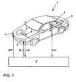
- Fig. 1 shows a motor vehicle 1 with a control unit 2.
- the control unit 2 is arranged on the motor vehicle, but shown separately for reasons of clarity.
- the motor vehicle has two adjustable by a respective actuator not shown headlights 7 and 8, wherein the optical axis of light of the headlights 7 and 8 by means of the actuators to the motor vehicle 1 by generated by the control unit 2 control commands SR * and SL * upwards and / or can be tilted down.
- An embodiment for such adjustment of headlights can, for example, the DE 100 44 512 A1 be removed.
- the control commands SR * and SL * may be the same or independent of each other.
- the motor vehicle 1 has a front axle 3 and a rear axle 4. On the front axle 3 and the rear axle 4 are each a sensor 5 and 6 for measuring the height of the front axle 3 and the height of the rear axle 4 are provided. Of the Sensors 5 and 6 are transmitted values HV and HH for the height of the front axle 3 and the height of the rear axle 4 to the control unit 2.
- Fig. 2 shows an embodiment for a control unit 2.
- the control unit 2 has a pitch angle estimator 10 for calculating a value N for the pitch angle of the motor vehicle 1 in response to values HV and HH for the height of the front axle 3 and the height of the rear axle 4.
- the control unit 2 also has a headlight controller 11 for calculating the control commands SR * and SL * as a function of the value N for the pitch angle of the motor vehicle 1.
- Fig. 3 This shows a preferred embodiment for a pitch angle estimator 10.
- This has a surface model 14 for determining the effects of unevenness of the surface (on which the vehicle moves) on the pitch angle, a correction device 16 for correcting the value HV of the height of the front axle 3 and Value HH of the height of the rear axle 4 to the determined by the surface model 14 effects of surface unevenness on the pitch angle and a pitch angle calculator 15.
- the correction device 16 has summation points 17 and 18, by means of which the FHV and FHH output from the surface model are subtracted from the value HV of the height of the front axle 3 and the value HH of the height of the rear axle 4, respectively.
- the value HVK of the height of the front axle 3 corrected by the ascertained effects of the unevenness of the surface and the value HHK of the height of the rear axle 4 corrected by the determined effects of the unevenness of the surface are input variables in the pitch angle calculator 15 for calculating the value N for the pitch angle.
- Fig. 4 shows a particularly advantageous embodiment of the surface model 14.
- the surface model 14 has a high-pass filter 20 for filtering the value HV of the height of the front axle 3 and for outputting a high-pass filtered Value GHV of the height of the front axle 3 and a high-pass filter 21 for filtering the value HH of the height of the rear axle 4 and for outputting a high-pass filtered value GHH of the height of the rear axle 4.
- the respective cutoff frequency of the high-pass filter is advantageously in a range between 0.1 Hz and 5 Hz, advantageously at a substantial 1 Hz.
- the surface model 14 has a correlator 22 of the high-pass filtered value GHV of the height of the front axle 3 and the high-pass filtered value GHH the height of the rear axle 4, only the changing proportions as uncorrelated value FHV the height of Front axle 3 and uncorrelated value FHH the height of the rear axle 4 outputs, which are not included in the other value.
- Fig. 5 shows a to the advantageous embodiment in Fig. 3 alternative embodiment for a pitch angle estimator 10. This is based on a mathematical model 12 of the motor vehicle.
- the coefficients B + C are adapted by the deviation dN of the vehicle inclination.
- Fig. 6 shows a to the embodiment in Fig. 2 Alternative embodiment for a control unit 2.
- the control unit 2 also has a pitch angle estimator 10 for calculating a value N for the pitch angle of the motor vehicle 1 as a function of the vehicle acceleration a.
- a pitch angle calculator 25 may also be used.
- the control unit 2 further has a filter 30 for generating a filtered value NG for the pitch angle of the motor vehicle 1 as a function of the value N for the pitch angle of the motor vehicle 1.
- a filter 30 for generating a filtered value NG for the pitch angle of the motor vehicle 1 as a function of the value N for the pitch angle of the motor vehicle 1.
- Embodiments of the adaptive filter 30 are shown in FIG Fig. 7 and in Fig. 8 explained.
- the control unit 2 also has a headlight controller 11 for calculating the control commands SR * and SL * as a function of the filtered value NG for the pitch angle of the motor vehicle 1.
- Fig. 7 shows an embodiment for the filter 30.
- the filter 30 has an adaptive filter 35 for outputting a filtered value NG for the pitch angle and a parameter calculator 36 for calculating at least one variable parameter P1 of the adaptive filter 35 as a function of the value N for the pitch angle and filtered value NG for the pitch angle.
- the adaptive filter 35 may be, for example, a low-pass filter and the at least one variable parameter P1 may be a cut-off frequency of the low-pass filter.
- the adaptive filter 35 may, for example, also be a temporal averager and the at least one variable parameter P1 may be the time duration over which the averaging means forms the mean value.
- Fig. 8 shows a particularly advantageous embodiment for the filter 30.
- the filter 30 has an adaptive filter 37 for outputting a filtered value NG for the pitch angle and a parameter calculator 38 for calculating at least one variable parameter P2 of the adaptive filter 37 as a function of the value N for the pitch angle and the filtered value NG for the pitch angle.
- the filter 30 also has a selector 39, by means of which a combined filtered value - in the present case designated NG1 - for the pitch angle is proportionally based on the value N (measured) of the pitch angle and the calculated NG1 value of the pitch angle as a function of a value N '. the first time derivative of the pitch angle ( Fig. 5 ). is picturable.
- the value N 'of the first time derivative of the pitch angle is calculated by the filter 30 and that in the specific embodiment by the adaptive filter 37.
- the adaptive filter 37 may in this case, for example, a mathematical model according to WO 92/10377 be.
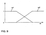
- NG w ⁇ 1 * NG ⁇ 1 + w ⁇ 2 * N
- w1 and w2 are weighting values dependent on the value N 'of the first time derivative of the pitch angle whose dependence on the value N' of the first time derivative of the pitch angle in Fig. 9 is shown.
Landscapes
- Engineering & Computer Science (AREA)
- Mechanical Engineering (AREA)
- Lighting Device Outwards From Vehicle And Optical Signal (AREA)
- Non-Portable Lighting Devices Or Systems Thereof (AREA)
Claims (22)
- Dispositif de phares pour un véhicule routier déplaçable sur une surface, notamment un véhicule automobile (1), comprenant au moins un phare (7, 8) pouvant être ajusté au moyen d'un actionneur, un axe de lumière optique du phare (7, 8) pouvant être incliné par rapport au véhicule routier vers le haut et/ou vers le bas au moyen de l'actionneur en fonction d'une valeur (N) de l'angle de tangage du véhicule routier, caractérisé en ce qu'un modèle de surface (14) est prévu pour déterminer des effets des irrégularités de la surface sur l'angle de tangage et un dispositif de correction (16) est prévu pour corriger la valeur (N), afin d'incliner vers le haut et/ou vers le bas l'axe de lumière optique du phare (7, 8) au moyen de l'actionneur en fonction de la valeur (N) corrigée de l'angle de tangage formée par le modèle de surface (14).
- Dispositif de phares selon la revendication 1, dans lequel le véhicule routier présente un essieu avant (3) et un essieu arrière (4) ainsi qu'un système de capteurs (5, 6) pour déterminer une valeur (HV) de la hauteur de l'essieu avant (3) et une valeur (HH) de la hauteur de l'essieu arrière (4), caractérisé en ce que le dispositif de correction (16) est réalisé pour effectuer la correction de la valeur (HV) de la hauteur de l'essieu avant (3) et de la valeur (HH) de la hauteur de l'essieu arrière (4) en tenant compte des effets déterminés des irrégularités de la surface sur l'angle de tangage.
- Dispositif de phares selon la revendication 2, caractérisé en ce qu'il présente un calculateur d'angle de tangage (15) pour calculer la valeur (N) de l'angle de tangage à partir des valeurs (HVK, HHK) de la hauteur de l'essieu avant (3) et de la hauteur de l'essieu arrière (4), corrigées en tenant compte des effets déterminés des irrégularités de la surface sur l'angle de tangage.
- Dispositif de phares selon la revendication 1, 2 ou 3, caractérisé en ce qu'un filtre adaptatif (35, 37) est prévu pour fournir une valeur filtrée (NG, NG1) de l'angle de tangage en fonction de la valeur (N) de l'angle de tangage, le filtre adaptatif (35, 37) présentant au moins un paramètre variable (P1, P2) qui est modifié en fonction de la valeur (N) de l'angle de tangage et de la valeur filtrée (NG, NG1) de l'angle de tangage.
- Dispositif de phares pour un véhicule routier, notamment un véhicule automobile (1), comprenant au moins un phare (7, 8) pouvant être ajusté au moyen d'un actionneur, un axe de lumière optique du phare (7, 8) pouvant être incliné par rapport au véhicule routier vers le haut et/ou vers le bas au moyen de l'actionneur, caractérisé en ce qu'un filtre adaptatif (35, 37) est prévu pour fournir une valeur filtrée (NG, NG1) de l'angle de tangage en fonction de la valeur (N) de l'angle de tangage, le filtre adaptatif (35, 37) présentant au moins un paramètre variable (P1, P2) qui peut être modifié en fonction de la valeur (N) de l'angle de tangage et de la valeur filtrée (NG, NG1) de l'angle de tangage, afin d'incliner vers le haut et/ou vers le bas l'axe de lumière optique du phare (7, 8) au moyen de l'actionneur en fonction du paramètre variable (P1, P2) formé par le filtre adaptatif (35, 37).
- Dispositif de phares selon les revendications 4 et 5, caractérisé en ce que l'axe de lumière optique du phare (7, 8) peut être incliné vers le haut et/ou vers le bas par rapport au véhicule routier au moyen de l'actionneur en fonction de la valeur filtrée (NG, NG1) de l'angle de tangage du véhicule routier.
- Dispositif de phares selon la revendication 6, caractérisé en ce que l'axe de lumière optique du phare (7, 8) peut être incliné vers le haut et/ou vers le bas par rapport au véhicule routier au moyen de l'actionneur également en fonction de la valeur (N) de l'angle de tangage du véhicule routier.
- Dispositif de phares selon l'une quelconque des revendications 4 à 7, caractérisé en ce que le filtre adaptatif (35) est un filtre passe-bas.
- Dispositif de phares selon la revendication 8, caractérisé en ce que l'au moins un paramètre variable (P1) est une fréquence limite du filtre passe-bas.
- Dispositif de phares selon l'une quelconque des revendications 4 à 9, caractérisé en ce que le filtre adaptatif (35) est un dispositif de génération de valeur moyenne temporel.
- Dispositif de phares selon la revendication 10, caractérisé en ce que l'au moins un paramètre variable (P1) est la durée pendant laquelle le dispositif de génération de valeur moyenne génère la valeur moyenne.
- Dispositif de phares selon l'une quelconque des revendications 4 à 7, caractérisé en ce que le filtre adaptatif (35, 37) est un modèle mathématique ou un réseau neuronal.
- Dispositif de phares selon l'une quelconque des revendications 4 à 12, caractérisé en ce qu'il présente un sélecteur (39) au moyen duquel une valeur combinée (NG) pour l'angle de tangage peut être formée en partie à partir de la valeur (N) de l'angle de tangage et de la valeur filtrée (NG1) de l'angle de tangage.
- Dispositif de phares selon la revendication 13, caractérisé en ce que l'axe de lumière optique du phare (7, 8) peut être incliné vers le haut et/ou vers le bas par rapport au véhicule routier au moyen de l'actionneur en fonction de la valeur combinée (NG) de l'angle de tangage.
- Dispositif de phares selon la revendication 13 ou 14, caractérisé en ce que la valeur combinée (NG) pour l'angle de tangage peut être formée au moyen du sélecteur (39) en partie à partir de la valeur (N) de l'angle de tangage et de la valeur filtrée (NG1) de l'angle de tangage en fonction d'une valeur (N') de la première dérivée dans le temps de l'angle de tangage.
- Dispositif de phares selon la revendication 15, caractérisé en ce que le filtre adaptatif (37) forme la valeur (N') de la première dérivée dans le temps de l'angle de tangage.
- Dispositif de phares selon l'une quelconque des revendications 5 à 16, dans lequel le véhicule routier peut se déplacer sur une surface, caractérisé en ce qu'un modèle de surface (14) est prévu pour déterminer des effets d'irrégularités de la surface sur l'angle de tangage.
- Dispositif de phares selon la revendication 17, caractérisé en ce qu'un dispositif de correction (16) est prévu pour corriger la valeur (N) de l'angle de tangage en tenant compte des effets déterminés des irrégularités de la surface sur l'angle de tangage.
- Dispositif de phares selon la revendication 17 ou 18, dans lequel le véhicule routier présente un essieu avant (3) et un essieu arrière (4) ainsi qu'un système de capteurs pour déterminer une valeur (HV) de la hauteur de l'essieu avant (3) et une valeur (HH) de la hauteur de l'essieu arrière (4), caractérisé en ce que le dispositif de correction (16) est réalisé pour effectuer la correction de la valeur (HV) de la hauteur de l'essieu avant (3) et de la valeur (HH) de la hauteur de l'essieu arrière (4) en tenant compte des effets déterminés des irrégularités de la surface sur l'angle de tangage.
- Dispositif de phares selon la revendication 19, caractérisé en ce qu'il présente un calculateur d'angle de tangage (15) pour calculer la valeur (N) de l'angle de tangage à partir des valeurs (HVK, HHK) de la hauteur de l'essieu avant (3) et de la hauteur de l'essieu arrière (4), corrigées en tenant compte des effets déterminés des irrégularités de la surface sur l'angle de tangage.
- Dispositif de phares pour un véhicule routier, notamment un véhicule automobile (1), comprenant au moins un phare (7, 8) pouvant être ajusté au moyen d'un actionneur, un axe de lumière optique du phare (7, 8) pouvant être incliné par rapport au véhicule routier vers le haut et/ou vers le bas au moyen de l'actionneur, en particulier, dispositif de phares selon l'une quelconque des revendications précédentes, caractérisé en ce que l'axe de lumière optique du phare (7, 8) peut être incliné par rapport au véhicule routier vers le haut et/ou vers le bas au moyen de l'actionneur en fonction d'une valeur formée en fonction d'une valeur (N') de la première dérivée dans le temps de l'angle de tangage.
- Véhicule routier, en particulier véhicule automobile (1), caractérisé en ce qu'il présente un dispositif de phares selon l'une quelconque des revendications précédentes.
Applications Claiming Priority (2)
| Application Number | Priority Date | Filing Date | Title |
|---|---|---|---|
| DE10309512A DE10309512A1 (de) | 2003-03-05 | 2003-03-05 | Scheinwerferanlage für ein Landfahrzeug |
| DE10309512 | 2003-03-05 |
Publications (2)
| Publication Number | Publication Date |
|---|---|
| EP1454792A1 EP1454792A1 (fr) | 2004-09-08 |
| EP1454792B1 true EP1454792B1 (fr) | 2008-07-30 |
Family
ID=32797811
Family Applications (1)
| Application Number | Title | Priority Date | Filing Date |
|---|---|---|---|
| EP04002640A Expired - Lifetime EP1454792B1 (fr) | 2003-03-05 | 2004-02-06 | Dispositif de phares pour véhicule routier |
Country Status (3)
| Country | Link |
|---|---|
| EP (1) | EP1454792B1 (fr) |
| AT (1) | ATE402844T1 (fr) |
| DE (2) | DE10309512A1 (fr) |
Families Citing this family (2)
| Publication number | Priority date | Publication date | Assignee | Title |
|---|---|---|---|---|
| DE102019102326A1 (de) * | 2019-01-30 | 2020-07-30 | Automotive Lighting Reutlingen Gmbh | Kraftfahrzeugscheinwerfer und Verfahren zum Betreiben eines Kraftfahrzeugscheinwerfers |
| DE102021106782A1 (de) | 2021-03-19 | 2022-09-22 | HELLA GmbH & Co. KGaA | Computerimplementiertes Verfahren zur Leuchtweitenregulierung |
Family Cites Families (6)
| Publication number | Priority date | Publication date | Assignee | Title |
|---|---|---|---|---|
| FR2505750B2 (fr) * | 1980-07-31 | 1985-09-27 | Dispositif pour le reglage dynamique de la position des projecteurs d'un vehicule | |
| DE3827983C1 (fr) * | 1988-08-18 | 1990-02-01 | Hella Kg Hueck & Co, 4780 Lippstadt, De | |
| DE4026553C2 (de) * | 1990-08-22 | 1997-07-10 | Siemens Ag | Vorrichtung zur Leuchtweitenregelung der Scheinwerfer in Kraftfahrzeugen |
| JP4036909B2 (ja) * | 1996-08-22 | 2008-01-23 | 株式会社デンソー | 車両用前照灯光軸方向自動調整装置 |
| JP3721052B2 (ja) * | 2000-06-15 | 2005-11-30 | 株式会社小糸製作所 | 自動車用ヘッドランプのオートレベリング装置 |
| GB2373222A (en) * | 2001-03-13 | 2002-09-18 | Michael Weir | Predictive vehicle suspension |
-
2003
- 2003-03-05 DE DE10309512A patent/DE10309512A1/de not_active Withdrawn
-
2004
- 2004-02-06 EP EP04002640A patent/EP1454792B1/fr not_active Expired - Lifetime
- 2004-02-06 DE DE502004007709T patent/DE502004007709D1/de not_active Expired - Lifetime
- 2004-02-06 AT AT04002640T patent/ATE402844T1/de not_active IP Right Cessation
Also Published As
| Publication number | Publication date |
|---|---|
| EP1454792A1 (fr) | 2004-09-08 |
| DE502004007709D1 (de) | 2008-09-11 |
| ATE402844T1 (de) | 2008-08-15 |
| DE10309512A1 (de) | 2004-09-30 |
Similar Documents
| Publication | Publication Date | Title |
|---|---|---|
| DE60105478T2 (de) | Vorrichtung zur automatischen Einstellung der Neigung des Lichtstrahls eines Kfz- Scheinwerfers | |
| EP2130718B1 (fr) | Procédé et dispositif de commande de l'émission de lumière d'au moins un phare frontal d'un véhicule | |
| DE19703665C2 (de) | Leuchtweitensteuerungsvorrichtung und Verfahren dazu | |
| DE69910461T2 (de) | Nickwinkelberechnungsvorrichtung für Fahrzeug | |
| DE69328393T2 (de) | Bremssteuerungssystem | |
| WO2013026607A1 (fr) | Procédé permettant de déterminer une déformation d'un tronçon de chaussée éclairé par au moins un projecteur d'un véhicule et procédé de commande d'une émission lumineuse d'au moins un projecteur d'un véhicule | |
| DE102012017118A1 (de) | Verfahren und System zum Optimieren des Fahrverhaltens eines Kraftfahrzeuges während der Fahrt | |
| DE102007000145B4 (de) | Steuerungssystem für einen Optikachsenwinkel eines Frontlichts | |
| DE102013201850A1 (de) | Vorrichtung und Verfahren zur Leuchtweitenregulierung | |
| DE102005003656A1 (de) | Automatisches Einstellsystem für die Fahrzeugscheinwerfer-Strahlrichtung | |
| DE60035140T2 (de) | Einrichtung zur Einstellung der optischen Achse eines Fahrzeugscheinwerfers | |
| DE102004058523B4 (de) | Verfahren zur Durchführung einer Neigungsänderung eines Kraftfahrzeuges | |
| EP1454792B1 (fr) | Dispositif de phares pour véhicule routier | |
| WO2008138435A1 (fr) | Procédé pour commander l'axe optique d'un phare de véhicule | |
| EP1078814B1 (fr) | Procédé et dispositif de commande de la distance d'éclairage d'un véhicule | |
| DE102019208812B4 (de) | Gesteuerte Nickneigung eines Fahrzeugs | |
| DE10128056C1 (de) | Verfahren zum Abgleichen einer Anordnung zum Messen der Gierrate eines Kraftfahrzeuges sowie eine solche Anordnung | |
| DE102012024985B4 (de) | Verfahren zum Bestimmen einer Soll-Kurvenneigung eines Kraftfahrzeugs beim Befahren eines kurvenförmigen Fahrbahnabschnitts | |
| DE102007021674B4 (de) | Verfahren zur Steuerung der optischen Achse eines Fahrzeugscheinwerfers | |
| DE602004009139T2 (de) | Vorrichtung zur automatischen Einstellung der Richtung einer optischen Achse eines Autoscheinwerfers | |
| DE602004001032T2 (de) | Methode um die Stellung der Lichtachse eines Fahrzeugscheinwerfers zu kontrollieren. | |
| DE10054606A1 (de) | Verfahren und Vorrichtung zur Leuchtweitenregelung der Scheinwerfer eines Kraftfahrzeugs | |
| DE102014112444B4 (de) | Verfahren zur Niveauregulierung | |
| EP1749696B1 (fr) | Procédé et dispositif de réglage de la portée des phares d'un véhicule automobile | |
| DE10055039A1 (de) | Verfahren zur Leuchtweitenregelung von Kraftfahrzeugbeleuchtungseinrichtungen und Leuchtweitenregelungseinrichtung |
Legal Events
| Date | Code | Title | Description |
|---|---|---|---|
| PUAI | Public reference made under article 153(3) epc to a published international application that has entered the european phase |
Free format text: ORIGINAL CODE: 0009012 |
|
| AK | Designated contracting states |
Kind code of ref document: A1 Designated state(s): AT BE BG CH CY CZ DE DK EE ES FI FR GB GR HU IE IT LI LU MC NL PT RO SE SI SK TR |
|
| AX | Request for extension of the european patent |
Extension state: AL LT LV MK |
|
| 17P | Request for examination filed |
Effective date: 20050308 |
|
| AKX | Designation fees paid |
Designated state(s): AT BE BG CH CY CZ DE DK EE ES FI FR GB GR HU IE IT LI LU MC NL PT RO SE SI SK TR |
|
| 17Q | First examination report despatched |
Effective date: 20051031 |
|
| GRAP | Despatch of communication of intention to grant a patent |
Free format text: ORIGINAL CODE: EPIDOSNIGR1 |
|
| GRAS | Grant fee paid |
Free format text: ORIGINAL CODE: EPIDOSNIGR3 |
|
| GRAA | (expected) grant |
Free format text: ORIGINAL CODE: 0009210 |
|
| AK | Designated contracting states |
Kind code of ref document: B1 Designated state(s): AT BE BG CH CY CZ DE DK EE ES FI FR GB GR HU IE IT LI LU MC NL PT RO SE SI SK TR |
|
| REG | Reference to a national code |
Ref country code: GB Ref legal event code: FG4D Free format text: NOT ENGLISH |
|
| REG | Reference to a national code |
Ref country code: CH Ref legal event code: EP |
|
| REF | Corresponds to: |
Ref document number: 502004007709 Country of ref document: DE Date of ref document: 20080911 Kind code of ref document: P |
|
| REG | Reference to a national code |
Ref country code: IE Ref legal event code: FG4D Free format text: LANGUAGE OF EP DOCUMENT: GERMAN |
|
| PG25 | Lapsed in a contracting state [announced via postgrant information from national office to epo] |
Ref country code: NL Free format text: LAPSE BECAUSE OF FAILURE TO SUBMIT A TRANSLATION OF THE DESCRIPTION OR TO PAY THE FEE WITHIN THE PRESCRIBED TIME-LIMIT Effective date: 20080730 Ref country code: ES Free format text: LAPSE BECAUSE OF FAILURE TO SUBMIT A TRANSLATION OF THE DESCRIPTION OR TO PAY THE FEE WITHIN THE PRESCRIBED TIME-LIMIT Effective date: 20081110 Ref country code: PT Free format text: LAPSE BECAUSE OF FAILURE TO SUBMIT A TRANSLATION OF THE DESCRIPTION OR TO PAY THE FEE WITHIN THE PRESCRIBED TIME-LIMIT Effective date: 20081230 |
|
| PG25 | Lapsed in a contracting state [announced via postgrant information from national office to epo] |
Ref country code: FI Free format text: LAPSE BECAUSE OF FAILURE TO SUBMIT A TRANSLATION OF THE DESCRIPTION OR TO PAY THE FEE WITHIN THE PRESCRIBED TIME-LIMIT Effective date: 20080730 Ref country code: SI Free format text: LAPSE BECAUSE OF FAILURE TO SUBMIT A TRANSLATION OF THE DESCRIPTION OR TO PAY THE FEE WITHIN THE PRESCRIBED TIME-LIMIT Effective date: 20080730 Ref country code: BG Free format text: LAPSE BECAUSE OF FAILURE TO SUBMIT A TRANSLATION OF THE DESCRIPTION OR TO PAY THE FEE WITHIN THE PRESCRIBED TIME-LIMIT Effective date: 20081030 |
|
| REG | Reference to a national code |
Ref country code: IE Ref legal event code: FD4D |
|
| PG25 | Lapsed in a contracting state [announced via postgrant information from national office to epo] |
Ref country code: DK Free format text: LAPSE BECAUSE OF FAILURE TO SUBMIT A TRANSLATION OF THE DESCRIPTION OR TO PAY THE FEE WITHIN THE PRESCRIBED TIME-LIMIT Effective date: 20080730 Ref country code: EE Free format text: LAPSE BECAUSE OF FAILURE TO SUBMIT A TRANSLATION OF THE DESCRIPTION OR TO PAY THE FEE WITHIN THE PRESCRIBED TIME-LIMIT Effective date: 20080730 Ref country code: IE Free format text: LAPSE BECAUSE OF FAILURE TO SUBMIT A TRANSLATION OF THE DESCRIPTION OR TO PAY THE FEE WITHIN THE PRESCRIBED TIME-LIMIT Effective date: 20080730 |
|
| PG25 | Lapsed in a contracting state [announced via postgrant information from national office to epo] |
Ref country code: SK Free format text: LAPSE BECAUSE OF FAILURE TO SUBMIT A TRANSLATION OF THE DESCRIPTION OR TO PAY THE FEE WITHIN THE PRESCRIBED TIME-LIMIT Effective date: 20080730 Ref country code: RO Free format text: LAPSE BECAUSE OF FAILURE TO SUBMIT A TRANSLATION OF THE DESCRIPTION OR TO PAY THE FEE WITHIN THE PRESCRIBED TIME-LIMIT Effective date: 20080730 Ref country code: CZ Free format text: LAPSE BECAUSE OF FAILURE TO SUBMIT A TRANSLATION OF THE DESCRIPTION OR TO PAY THE FEE WITHIN THE PRESCRIBED TIME-LIMIT Effective date: 20080730 |
|
| PLBE | No opposition filed within time limit |
Free format text: ORIGINAL CODE: 0009261 |
|
| STAA | Information on the status of an ep patent application or granted ep patent |
Free format text: STATUS: NO OPPOSITION FILED WITHIN TIME LIMIT |
|
| 26N | No opposition filed |
Effective date: 20090506 |
|
| BERE | Be: lapsed |
Owner name: VOLKSWAGEN A.G. Effective date: 20090228 |
|
| PG25 | Lapsed in a contracting state [announced via postgrant information from national office to epo] |
Ref country code: MC Free format text: LAPSE BECAUSE OF NON-PAYMENT OF DUE FEES Effective date: 20090228 |
|
| REG | Reference to a national code |
Ref country code: CH Ref legal event code: PL |
|
| PG25 | Lapsed in a contracting state [announced via postgrant information from national office to epo] |
Ref country code: LI Free format text: LAPSE BECAUSE OF NON-PAYMENT OF DUE FEES Effective date: 20090228 Ref country code: CH Free format text: LAPSE BECAUSE OF NON-PAYMENT OF DUE FEES Effective date: 20090228 |
|
| PG25 | Lapsed in a contracting state [announced via postgrant information from national office to epo] |
Ref country code: SE Free format text: LAPSE BECAUSE OF FAILURE TO SUBMIT A TRANSLATION OF THE DESCRIPTION OR TO PAY THE FEE WITHIN THE PRESCRIBED TIME-LIMIT Effective date: 20081030 |
|
| PG25 | Lapsed in a contracting state [announced via postgrant information from national office to epo] |
Ref country code: BE Free format text: LAPSE BECAUSE OF NON-PAYMENT OF DUE FEES Effective date: 20090228 |
|
| PG25 | Lapsed in a contracting state [announced via postgrant information from national office to epo] |
Ref country code: AT Free format text: LAPSE BECAUSE OF NON-PAYMENT OF DUE FEES Effective date: 20090206 |
|
| PG25 | Lapsed in a contracting state [announced via postgrant information from national office to epo] |
Ref country code: GR Free format text: LAPSE BECAUSE OF FAILURE TO SUBMIT A TRANSLATION OF THE DESCRIPTION OR TO PAY THE FEE WITHIN THE PRESCRIBED TIME-LIMIT Effective date: 20081031 |
|
| PG25 | Lapsed in a contracting state [announced via postgrant information from national office to epo] |
Ref country code: LU Free format text: LAPSE BECAUSE OF NON-PAYMENT OF DUE FEES Effective date: 20090206 |
|
| PG25 | Lapsed in a contracting state [announced via postgrant information from national office to epo] |
Ref country code: HU Free format text: LAPSE BECAUSE OF FAILURE TO SUBMIT A TRANSLATION OF THE DESCRIPTION OR TO PAY THE FEE WITHIN THE PRESCRIBED TIME-LIMIT Effective date: 20090131 |
|
| PG25 | Lapsed in a contracting state [announced via postgrant information from national office to epo] |
Ref country code: TR Free format text: LAPSE BECAUSE OF FAILURE TO SUBMIT A TRANSLATION OF THE DESCRIPTION OR TO PAY THE FEE WITHIN THE PRESCRIBED TIME-LIMIT Effective date: 20080730 |
|
| PG25 | Lapsed in a contracting state [announced via postgrant information from national office to epo] |
Ref country code: CY Free format text: LAPSE BECAUSE OF FAILURE TO SUBMIT A TRANSLATION OF THE DESCRIPTION OR TO PAY THE FEE WITHIN THE PRESCRIBED TIME-LIMIT Effective date: 20080730 |
|
| PGFP | Annual fee paid to national office [announced via postgrant information from national office to epo] |
Ref country code: IT Payment date: 20120222 Year of fee payment: 9 |
|
| PGFP | Annual fee paid to national office [announced via postgrant information from national office to epo] |
Ref country code: GB Payment date: 20130228 Year of fee payment: 10 |
|
| GBPC | Gb: european patent ceased through non-payment of renewal fee |
Effective date: 20140206 |
|
| PG25 | Lapsed in a contracting state [announced via postgrant information from national office to epo] |
Ref country code: GB Free format text: LAPSE BECAUSE OF NON-PAYMENT OF DUE FEES Effective date: 20140206 |
|
| REG | Reference to a national code |
Ref country code: FR Ref legal event code: PLFP Year of fee payment: 13 |
|
| PG25 | Lapsed in a contracting state [announced via postgrant information from national office to epo] |
Ref country code: IT Free format text: LAPSE BECAUSE OF NON-PAYMENT OF DUE FEES Effective date: 20140206 |
|
| REG | Reference to a national code |
Ref country code: FR Ref legal event code: PLFP Year of fee payment: 14 |
|
| REG | Reference to a national code |
Ref country code: FR Ref legal event code: PLFP Year of fee payment: 15 |
|
| PGFP | Annual fee paid to national office [announced via postgrant information from national office to epo] |
Ref country code: DE Payment date: 20200229 Year of fee payment: 17 |
|
| PGFP | Annual fee paid to national office [announced via postgrant information from national office to epo] |
Ref country code: FR Payment date: 20200225 Year of fee payment: 17 |
|
| REG | Reference to a national code |
Ref country code: DE Ref legal event code: R119 Ref document number: 502004007709 Country of ref document: DE |
|
| PG25 | Lapsed in a contracting state [announced via postgrant information from national office to epo] |
Ref country code: DE Free format text: LAPSE BECAUSE OF NON-PAYMENT OF DUE FEES Effective date: 20210901 Ref country code: FR Free format text: LAPSE BECAUSE OF NON-PAYMENT OF DUE FEES Effective date: 20210228 |