EP1453415B1 - Endoskop - Google Patents
Endoskop Download PDFInfo
- Publication number
- EP1453415B1 EP1453415B1 EP03811373A EP03811373A EP1453415B1 EP 1453415 B1 EP1453415 B1 EP 1453415B1 EP 03811373 A EP03811373 A EP 03811373A EP 03811373 A EP03811373 A EP 03811373A EP 1453415 B1 EP1453415 B1 EP 1453415B1
- Authority
- EP
- European Patent Office
- Prior art keywords
- endoscope
- shaft
- accordance
- optical device
- relative
- Prior art date
- Legal status (The legal status is an assumption and is not a legal conclusion. Google has not performed a legal analysis and makes no representation as to the accuracy of the status listed.)
- Expired - Lifetime
Links
- 230000003287 optical effect Effects 0.000 claims abstract description 48
- 239000012530 fluid Substances 0.000 claims description 8
- 238000004891 communication Methods 0.000 claims description 5
- 238000003745 diagnosis Methods 0.000 description 5
- 230000002349 favourable effect Effects 0.000 description 4
- 238000001356 surgical procedure Methods 0.000 description 3
- 238000010276 construction Methods 0.000 description 2
- 230000006378 damage Effects 0.000 description 2
- 208000027418 Wounds and injury Diseases 0.000 description 1
- 238000001574 biopsy Methods 0.000 description 1
- 238000007598 dipping method Methods 0.000 description 1
- 238000007599 discharging Methods 0.000 description 1
- 210000003811 finger Anatomy 0.000 description 1
- 208000014674 injury Diseases 0.000 description 1
- 238000002324 minimally invasive surgery Methods 0.000 description 1
- 238000012544 monitoring process Methods 0.000 description 1
- 230000000284 resting effect Effects 0.000 description 1
- 210000003813 thumb Anatomy 0.000 description 1
Images


Classifications
-
- A—HUMAN NECESSITIES
- A61—MEDICAL OR VETERINARY SCIENCE; HYGIENE
- A61B—DIAGNOSIS; SURGERY; IDENTIFICATION
- A61B1/00—Instruments for performing medical examinations of the interior of cavities or tubes of the body by visual or photographical inspection, e.g. endoscopes; Illuminating arrangements therefor
- A61B1/313—Instruments for performing medical examinations of the interior of cavities or tubes of the body by visual or photographical inspection, e.g. endoscopes; Illuminating arrangements therefor for introducing through surgical openings, e.g. laparoscopes
-
- A—HUMAN NECESSITIES
- A61—MEDICAL OR VETERINARY SCIENCE; HYGIENE
- A61B—DIAGNOSIS; SURGERY; IDENTIFICATION
- A61B1/00—Instruments for performing medical examinations of the interior of cavities or tubes of the body by visual or photographical inspection, e.g. endoscopes; Illuminating arrangements therefor
- A61B1/00163—Optical arrangements
- A61B1/00165—Optical arrangements with light-conductive means, e.g. fibre optics
-
- A—HUMAN NECESSITIES
- A61—MEDICAL OR VETERINARY SCIENCE; HYGIENE
- A61B—DIAGNOSIS; SURGERY; IDENTIFICATION
- A61B17/00—Surgical instruments, devices or methods
- A61B17/28—Surgical forceps
- A61B17/29—Forceps for use in minimally invasive surgery
-
- A—HUMAN NECESSITIES
- A61—MEDICAL OR VETERINARY SCIENCE; HYGIENE
- A61B—DIAGNOSIS; SURGERY; IDENTIFICATION
- A61B18/00—Surgical instruments, devices or methods for transferring non-mechanical forms of energy to or from the body
- A61B18/04—Surgical instruments, devices or methods for transferring non-mechanical forms of energy to or from the body by heating
- A61B18/12—Surgical instruments, devices or methods for transferring non-mechanical forms of energy to or from the body by heating by passing a current through the tissue to be heated, e.g. high-frequency current
- A61B18/14—Probes or electrodes therefor
-
- A—HUMAN NECESSITIES
- A61—MEDICAL OR VETERINARY SCIENCE; HYGIENE
- A61B—DIAGNOSIS; SURGERY; IDENTIFICATION
- A61B90/00—Instruments, implements or accessories specially adapted for surgery or diagnosis and not covered by any of the groups A61B1/00 - A61B50/00, e.g. for luxation treatment or for protecting wound edges
- A61B90/36—Image-producing devices or illumination devices not otherwise provided for
- A61B90/361—Image-producing devices, e.g. surgical cameras
Definitions
- the invention relates to an endoscope having a proximal end region and a distal end region insertable into a human body, having a shaft extending in a longitudinal direction and having an optic which can be moved relative to the shaft in the longitudinal direction.
- Endoscopes of the type described above are used for various purposes in the context of minimally invasive procedures in the human body. With the help of the shaft passing through the optics, an operator can see the surgical area.
- the optic can be introduced from the proximal end into the shaft and can be displaced in the axial direction. A disadvantage has been found here that the optics can be moved uncontrollably.
- This object is achieved in a generic endoscope characterized in that the optics can be fixed relative to the shaft in a first position and in at least a second, different from the first position position in the axial direction.
- This configuration makes it possible for the optics to be held in precisely defined positions at least in the longitudinal direction of the shaft. An undesirable relative movement between the shaft and the optics is thereby avoided.
- the optics can be used in the desired manner. For example, in the diagnosis position, it can protrude far beyond the distal end of the endoscope without the distal end of the endoscope or tools arranged thereon impairing a view of the surgical area.
- the optics By transferring the optics from the diagnosis position into the second position serving, for example, as a working position, optical monitoring of an insert of tools arranged on the shaft is possible in a defined manner.
- the optics can be set in the axial direction in a particularly simple manner if at least one latching device is provided for fixing the optics in the first and / or the second position.
- the optics can thereby be set automatically when one of the two predetermined positions is reached.
- the locking device By appropriate design of the locking device, the fixed optics can also be released again and moved in the axial direction.
- the optic is fixed in the first position and / or in the second position relative to the shaft in the circumferential direction. This results in a completely defined position of the optics relative to the shaft.
- the optics can be fixed in a third position in the axial direction and freely rotatable about the longitudinal axis of the shaft.
- the optic may be completely retracted into the interior of the shaft, protecting it against external influences.
- a rotatability that is free about the longitudinal axis of the shaft makes it possible to arbitrarily orient connecting leads emerging from a proximal end of the optic.
- the distal end of the optic protrudes beyond the distal end of the endoscope in the first position.
- an optically visible operating region is not restricted by the endoscope or elements arranged thereon.
- the distal end of the optic projects beyond the distal end of the shaft and the distal end of the endoscope projects beyond the optic. If the second position is provided in this way, the distal end of the endoscope, formed for example by tool elements projecting from the shaft, can be viewed by means of the optics. A movement of applied tool elements is optically controllable.
- the endoscope comprises an optical pickup device, that the optical pickup device relative to the shaft movable and in the first and / or in the second and / or in the third position in axial Direction is fixed.
- the at least one position in which the optics can be fixed relative to the shaft in the axial direction is now defined by a corresponding configuration of the endoscope and the optical pickup device.
- the optic is freely rotatable relative to the optical pickup device about the longitudinal axis.
- the optics can be freely rotated even with axially fixed optical pickup device and an operating area can be viewed freely.
- outgoing from a proximal end of the optics connecting lines can be oriented in the desired manner.
- the latching device comprises a latching element which is movable relative to a latching recess, if the latching recess or latching element is arranged on the optics or the optics receiving device and if the latching element or the latching recess acts on a receptacle of the endoscope for optics or the optical pickup device are arranged.
- a determination of the respective position is achieved by immersing the locking member in the recess. Conversely, a release in a simple manner achievable that the locking member is led out of the recess.
- the endoscope an inflow channel for supplying a Fluids from the proximal to the distal end region, a drainage channel for discharging a fluid from the distal to the proximal end region, an inlet connection in fluid communication with the inlet channel and a drainage connection in flow communication with the drainage. Due to this configuration, a fluid can be directed via the inflow port from the proximal end to the distal end of the endoscope and exiting there, for example, to flush the operating area. At the same time, the fluid or remote body tissue can be discharged through the drainage channel.
- the inflow connection, the outflow connection and the optics are rotatable relative to each other about an axis of rotation extending essentially in the longitudinal direction of the shaft. This can be arranged from the respective terminals outgoing leads in any position, which also reduces the risk that the leads are twisted or knotted together.
- the inflow connection, the outflow connection and the optics are rotatable relative to the shaft about the axis of rotation extending essentially in the longitudinal direction of the shaft.
- the shaft can be introduced into the interior of the body due to this configuration and remain there unrotatable.
- outgoing from the inflow port, the drain port or the optics lines can be arbitrarily oriented so as not to hinder a surgeon or prevent twisting of the lines.
- the stem which is thus resting within the body, a risk of injury to the interior of the body due to a rotation of the stem is virtually ruled out.
- At least one movable tool is arranged at the distal end of the shaft.
- the tool may be for example a forceps, a pair of scissors or the like.
- the movable tool is rotatable relative to the shaft about an axis of rotation extending substantially in the longitudinal direction of the shaft. In this way, a relative position of the movable tool relative to a shaft fixed in the interior of the body can be changed as desired.
- the tool comprises at least one movable relative to the shaft jaw part.
- a pair of scissors or a forceps can be formed in a simple manner.
- At least two mutually movable jaw parts are provided. These can, for example, be pivoted outward far beyond a cross-sectional area of the shaft and capture body tissue, in particular in the removal of septa, polyps or the like, which are partially larger in cross section than the cross section of the shaft inserted into the interior of the body.
- the at least one movable jaw part moves relative to the shaft about a substantially transversely to the longitudinal direction of the shaft Swivel axis is pivotable.
- a pivoting movement of the jaw part can be realized in a particularly simple manner, in particular a lateral pivoting of the jaw part.
- an actuating device assigned to the at least one jaw part is provided and the actuating device can be rotated relative to the shaft. With the actuating device, a movement of the jaw part can be realized. Due to the rotatability of the actuator relative to the shaft can be concluded from the position of the actuator to the relative orientation of the associated jaw part.
- the actuating device can be locked in an actuated position of the at least one movable jaw part.
- a lock could also be conceivable in an open position of the jaws.
- the optics is arranged in the region of the at least two jaw parts on one side of the stationary jaw part and the movable jaw part on the side facing away from the optics of the stationary jaw part.
- the optics are arranged outside the working area of the two jaw parts and can not get caught between them and get damaged. It is rather protected in this way.
- a particularly good protection of the optics results when the stationary jaw part is concavely curved pointing in the direction of the optics.
- the optics can thus cling to the concave area of the jaw part.
- the cross section of the insertable into the body portion of the endoscope is minimized.
- the shaft comprises a distal end of the endoscope adjacent, insertable into a human body shaft portion, that the axis of symmetry of the optics in the region of the shaft portion parallel to the axis of symmetry of the shaft in the region of the shaft portion and that both axes of symmetry are spaced from each other.
- Such an eccentric arrangement of the longitudinal axes of the shaft portion and the optics makes it possible that the shaft and in particular arranged on this tool around the optics are rotatable.
- the longitudinal axis of the optic overall also forms the axis of rotation for the entire region of the endoscope which can be introduced into the interior of the body.
- an RF connection device is provided for connecting the endoscope to a high-frequency generator and if this connection device is arranged rotatable relative to the optics. As a result, it is also possible to arrange connection lines in the desired orientation and to prevent twisting of the connecting lines.
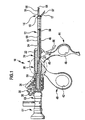
- FIG. 1 shows an endoscope, generally designated by the reference numeral 10, with a shaft 12 insertable through a body opening into the interior of a human body, at its distal end a surgical tool in the form of a forceps 14 relative to the shaft about its longitudinal axis is rotatably arranged.
- the grasping forceps comprises a stationary jaw part 16 and a jaw part 17 pivotably mounted about a pivot axis 18 extending transversely to the longitudinal axis of the shaft 12.
- a handling region 20 of the endoscope 10 connects, which comprises a rigidly connected to an outer shaft sleeve 13 of the shaft 12 main body 22.
- an optical channel 24 which extends in the region of the base body 22 in the direction of its proximal end in one stage, so that an annular stop 26 is formed.
- an inflow connection 28 and an outflow connection 30 are provided around the latter and relatively rotatable, which are each in fluid communication with a lenticular cross-section, through the base body 22 and the shaft 12 extending inflow channel 32 and discharge channel 34.
- an RF terminal 36 which is not shown via electrical connections, which extend in the longitudinal direction through the shaft 12, with the two jaw members 16 and 17 in conjunction.
- a grip region 38 Rotatable around a distal region of the base body 22 is a grip region 38, which has a fixed sector 40 projecting from the base body 22 in the proximal direction with a thumb opening 20 and a handle section 38 relative to the branch 40 about a transversely to the longitudinal axis of the shaft 12 extending pivot axis 45 pivotable industry 44 with a finger opening 46 includes.
- a push and pull rod 50 is used, the proximal end of which is movable mounted on the industry 44 and the distal end is connected via laterally projecting, in guide slots 52 of the jaw part 17 dipping bearing pin 54 movably connected to the jaw part 17.
- a pivot position of the industry 44 can be locked relative to the industry 40, whereby the movable jaw member 17 is held in a desired position, for example, in contact with the stationary jaw member 16 or in an open position, in which it laterally from the jaw member 16th is spread apart.
- a guide sleeve 58 is inserted on the proximal side, which abuts with its distal end almost to the stop 26.
- the guide sleeve 58 is part of an optical adapter 68 via which a proximal-side connection region 61 of an optical system 60 can be connected to other optical devices, for example a camera or a microscope or the like.
- a connection between the optical adapter 68 and the terminal portion 61 can be an axial location of the two elements, for example, achieve a releasable latching connection.
- a relative axial movement between the guide sleeve 58 and the optics 60 is thereby prevented in the connected state.
- the latching connection can be designed so that a rotation of the terminal portion 61 relative to the optical adapter 68 is possible.
- the rod-shaped optic 60 can be inserted from the proximal end of the endoscope 10, which has a bevelled 64 relative to its longitudinal axis end 64, which is formed by a relative to the longitudinal axis 62 inclined by an inclination angle 66 surface.
- the guide sleeve 58 is, as shown in Figures 2, 3 and 6, adjacent its distal end provided with an annular groove 70, starting from the starting in the proximal direction along its outer surface a flattening 74 in about half the length of the guide sleeve 58th extends.
- a flattening 74 in about half the length of the guide sleeve 58th extends.
- a longitudinal groove 72 instead of the flat 74 and a longitudinal groove 72 may be provided.
- two hollow-spherical recesses 76 and 78 are recessed on the guide sleeve 58, wherein the distance between the recess 76 and the recess 78 corresponds approximately to the length of the movable jaw member 17.
- the distance between the recess 76 and the annular groove 70 is significantly smaller.
- a threaded pin 84 is inserted, the end 88 either, as shown for example in Figure 4, corresponding to the longitudinal groove 72 is formed or has a flattened end 88 corresponding to the flattening 74, as shown in particular in Figure 3.
- a grub screw 90 is used, at which a coil spring 92 is supported in the direction of the guide sleeve 58 and a ball 94 presses against the guide sleeve 58.
- a ball pressure piece over which a latching connection with the two, provided on the guide sleeve 58, recesses forming recesses 76 and 78 can be made.
- the threaded pin 84 is screwed into the threaded hole 80 so far that the end 88 dips into the longitudinal groove 72 and thereby the guide sleeve 58 is guided in the longitudinal direction thereof.
- the guide sleeve 58 is fixed in the axial direction relative to the handle portion 38 and thus to the shaft 12 when the ball 94 dips into one of the two recesses 76 or 78 or in the annular groove 70. In the latter case, a rotation of the grip portion 38 about the optical adapter 68 is possible.
- the ball 94 dips into the recess 78.
- the end 64 of the optic 60 protrudes slightly beyond the end of the fixed jaw part 16 in the distal direction in the diagnosis position. In this way, an operating area can be viewed without the two jaws 16 and 17 affect the view. This is shown in FIGS. 4 and 5.
- the ball 94 dips into the recess 76 a.
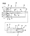
- the end 64 of the optic 60 protrudes in this position slightly beyond the optical channel 24 from the shaft 12, but not beyond the distal end of the stationary jaw part 16 addition. In this working position can be observed with the optics 60 by means of the jaws 16 and 17 performed surgery.
- the ball 94 finally plunges into the annular groove 70, into which the free end 88 of the threaded pin 84 simultaneously enters, thereby allowing rotation of the guide sleeve 58 relative to the handle region 38.
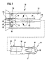
- the end 64 of the optic 60 is retracted into the optical channel 24, so that the end 64 is protected.
- the longitudinal axis 62 of the optics 60 is offset parallel to the longitudinal axis in the region of the shaft 12, resulting in an overall eccentric rotation of the shaft 12 to the optics 60 results.
- the optics 60 nestles in the region of the stationary jaw part 16, which, like the jaw part 17, is provided with an elongated transverse opening 96 or 97, into a concave depression 98 of the stationary jaw part 16 pointing radially outwards.
- the optics 60 is guided on a side facing away from the movable jaw part 17 of the stationary jaw part. Damage to the optics 60 by the two jaws 16 and 17 is thereby avoided.
Landscapes
- Health & Medical Sciences (AREA)
- Life Sciences & Earth Sciences (AREA)
- Surgery (AREA)
- Optics & Photonics (AREA)
- Physics & Mathematics (AREA)
- Biomedical Technology (AREA)
- Medical Informatics (AREA)
- Radiology & Medical Imaging (AREA)
- Nuclear Medicine, Radiotherapy & Molecular Imaging (AREA)
- Engineering & Computer Science (AREA)
- Biophysics (AREA)
- Heart & Thoracic Surgery (AREA)
- Pathology (AREA)
- Molecular Biology (AREA)
- Animal Behavior & Ethology (AREA)
- General Health & Medical Sciences (AREA)
- Public Health (AREA)
- Veterinary Medicine (AREA)
- Endoscopes (AREA)
- Eye Examination Apparatus (AREA)
Description
- Die Erfindung betrifft ein Endoskop mit einem proximalen und einem in einen menschlichen Körper einführbaren distalen Endbereich, mit einem sich in einer Längsrichtung erstreckenden Schaft und mit einer den Schaft in Längsrichtung durchsetzenden, relativ zum Schaft bewegbaren Optik.
- Endoskope der eingangs beschriebenen Art werden zu verschiedenen Zwecken im Rahmen minimal invasiver Eingriffe in den menschlichen Körper verwendet. Mit Hilfe der den Schaft durchsetzenden Optik kann ein Operateur den Operationsbereich einsehen. Bei herkömmlichen Endoskopen ist die Optik von proximal in den Schaft einführbar und in axialer Richtung verschiebbar. Als nachteilig hat sich hierbei erwiesen, daß die Optik unkontrolliert bewegt werden kann.
- Aus der US 6,129,683 ist eine optische Biopsiezange mit einem Schaft und einer den Schaft in Längsrichtung durchsetzenden, relativ zum Schaft bewegbaren Optik bekannt. Femer wird in der US 4,765,314 eine Vorrichtung zum Einführen eines Endoskops oder eines chirurgischen Instruments in einen Körperhohlraum offenbart.
- Es ist daher Aufgabe der vorliegenden Erfindung, ein Endoskop der eingangs genannten Art so zu verbessern, daß die Optik einfacher und sicherer handhabbar ist.
- Diese Aufgabe wird bei einem gattungsgemäßen Endoskop dadurch gelöst, daß die Optik relativ zum Schaft in einer ersten Stellung und in mindestens einer zweiten, von der ersten Stellung verschiedenen Stellung in axialer Richtung festlegbar ist.
- Diese Ausgestaltung ermöglicht es, daß die Optik zumindest in Längsrichtung des Schafts in genau definierten Positionen gehalten wird. Eine unerwünschte Relativbewegung zwischen dem Schaft und der Optik wird dadurch vermieden. Durch Auswahl von zwei Stellungen, beispielsweise einer Diagnosestellung und einer Arbeitsstellung, kann die Optik in gewünschter Weise eingesetzt werden. So kann sie in der Diagnosestellung zum Beispiel bis weit über das distale Ende des Endoskops hinausragen, ohne daß das distale Ende des Endoskops oder daran angeordnete Werkzeuge eine Sicht auf den Operationsbereich beeinträchtigen. Durch Überführung der Optik von der Diagnosestellung in die zweite, beispielsweise als Arbeitsstellung dienende Stellung, wird in definierter Weise eine optische Überwachung eines Einsatzes von am Schaft angeordneten Werkzeugen möglich. In der zweiten Stellung könnte ein freies Ende der Optik jedoch auch bis in den Schaft hinein zurückgezogen sein, so daß die Optik geschützt ist. Durch die Möglichkeit der axialen Festlegung der Optik relativ zum Schaft in zwei Stellungen läßt sich das Endoskop wesentlich einfacher und sicherer handhaben.
- Besonders einfach läßt sich die Optik in axialer Richtung festlegen, wenn mindestens eine Rastvorrichtung zur Festlegung der Optik in der ersten und/oder der zweiten Stellung vorgesehen ist. Insbesondere kann die Optik dadurch automatisch bei Erreichen einer der beiden vorbestimmten Stellungen festgelegt werden. Durch entsprechende Ausgestaltung der Rastvorrichtung kann die festgelegte Optik auch wieder freigegeben und in axialer Richtung bewegt werden.
- Vorzugsweise ist die Optik in der ersten Stellung und/oder in der zweiten Stellung relativ zum Schaft in Umfangsrichtung festgelegt. Dadurch ergibt sich eine vollständig definierte Stellung der Optik relativ zum Schaft.
- Günstig ist es, wenn die Optik in einer dritten Stellung in axialer Richtung festlegbar und um die Längsachse des Schaftes frei rotierbar ist. In der dritten Stellung kann die Optik beispielsweise vollständig in das Innere des Schafts zurückgezogen sein, wodurch sie gegen äußere Einflüsse geschützt ist. Eine um die Längsachse des Schaftes freie Rotierbarkeit ermöglicht es, von einem proximalen Ende der Optik abgehende Anschlußleitungen beliebig zu orientieren.
- Bei einer bevorzugten Ausführungsform der Erfindung kann vorgesehen sein, daß das distale Ende der Optik in der ersten Stellung über das distale Ende des Endoskops hervorsteht. Dadurch wird ein von der Optik einsehbarer Operationsbereich durch das Endoskop oder daran angeordnete Elemente nicht eingeschränkt.
- Günstig ist es, wenn in der zweiten Stellung das distale Ende der Optik über das distale Ende des Schafts und das distale Ende des Endoskops über die Optik hervorsteht. Wenn die zweite Stellung derart vorgesehen ist, kann mittels der Optik das distale, beispielsweise durch vom Schaft abstehende Werkzeugelemente gebildete Ende des Endoskops eingesehen werden. Eine Bewegung von zur Anwendung kommenden Werkzeugelementen ist so optisch kontrollierbar.
- Um herkömmliche Optiken in Verbindung mit einem erfindungsgemäßen Endoskop verwenden zu können, kann vorgesehen sein, daß das Endoskop eine Optikaufnahmevorrichtung umfaßt, daß die Optikaufnahmevorrichtung relativ zum Schaft bewegbar und in der ersten und/oder in der zweiten und/oder in der dritten Stellung in axialer Richtung festlegbar ist. Die mindestens eine Stellung, in der die Optik relativ zum Schaft in axialer Richtung festlegbar ist, wird nunmehr definiert durch eine entsprechende Ausgestaltung des Endoskops und der Optikaufnahmevorrichtung.
- Vorzugsweise ist die Optik relativ zur Optikaufnahmevorrichtung um die Längsachse frei verdrehbar. Auf diese Weise kann die Optik auch bei axial festgelegter Optikaufnahmevorrichtung frei verdreht und ein Operationsbereich frei eingesehen werden. Ferner lassen sich von einem proximalen Ende der Optik abgehende Anschlußleitungen in gewünschter Weise orientieren.
- Ein besonders einfacher Aufbau der Rastvorrichtung ergibt sich, wenn die Rastvorrichtung ein relativ zu einer Rastausnehmung bewegbares Rastglied umfaßt, wenn die Rastausnehmung oder das Rastglied an der Optik oder der Optikaufnahmevorrichtung angeordnet sind und wenn das Rastglied oder die Rastausnehmung an einer Aufnahme des Endoskops für die Optik oder die Optikaufnahmevorrichtung angeordnet sind. Eine Festlegung der jeweiligen Stellung wird erreicht, durch Eintauchen des Rastglieds in die Rastausnehmung. Umgekehrt ist ein Lösen auf einfache Weise dadurch erreichbar, daß das Rastglied aus der Rastausnehmung herausgeführt wird.
- Gemäß einer weiteren bevorzugten Ausführungsform der Erfindung kann vorgesehen sein, daß das Endoskop einen Zuflußkanal zum Zuführen eines Fluids vom proximalen zum distalen Endbereich, einen Abflußkanal zum Abführen eines Fluids vom distalen zum proximalen Endbereich, einen mit dem Zuflußkanal in Strömungsverbindung stehenden Zuflußanschluß und einen mit dem Abfluß in Strömungsverbindung stehenden Abflußanschluß umfaßt. Aufgrund dieser Ausgestaltung kann ein Fluid über den Zuflußanschluß vom proximalen Ende zum distalen Ende des Endoskops geleitet werden und beispielsweise dort austreten, um den Operationsbereich zu spülen. Gleichzeitig kann durch den Abflußkanal das Fluid oder entferntes Körpergewebe abgeleitet werden.
- Günstig ist es, wenn der Zuflußanschluß, der Abflußanschluß und die Optik relativ zueinander um eine im wesentlichen in Längsrichtung des Schafts verlaufende Drehachse drehbar sind. Damit lassen sich von den jeweiligen Anschlüssen abgehende Anschlußleitungen in einer beliebigen Stellung anordnen, wodurch auch die Gefahr vermindert wird, daß die Anschlußleitungen verdrillt oder miteinander verknotet werden.
- Weiterhin ist es vorteilhaft, wenn der Zuflußanschluß, der Abflußanschluß und die Optik relativ zum Schaft um die im wesentlichen in Längsrichtung des Schafts verlaufende Drehachse drehbar sind. Der Schaft kann aufgrund dieser Ausgestaltung in das Körperinnere eingeführt werden und dort unverdrehbar liegenbleiben. Dagegen können vom Zuflußanschluß, vom Abflußanschluß oder von der Optik abgehende Leitungen beliebig orientiert werden, um einen Operateur nicht zu behindern oder ein Verdrillen der Leitungen zu verhindern. Durch den auf diese Weise innerhalb des Körpers ruhenden Schaft wird ferner eine Verletzungsgefahr für das Körperinnere aufgrund einer Rotation des Schafts praktisch ausgeschlossen.
- Um einen Operationsbereich mit dem Endoskop nicht nur beobachten zu können, sondern zum eigentlichen Durchführen eines chirurgischen Eingriffs, ist es günstig, wenn am distalen Ende des Schafts mindestens ein bewegliches Werkzeug angeordnet ist. Das Werkzeug kann beispielsweise eine Fasszange, eine Schere oder dergleichen sein.
- Vorteilhaft ist es, wenn das bewegliche Werkzeug relativ zum Schaft um eine im wesentlichen in Längsrichtung des Schaftes verlaufende Drehachse verdrehbar ist. Damit kann eine relative Stellung des beweglichen Werkzeugs relativ zu einem im Körperinneren feststehenden Schaft beliebig verändert werden.
- Bei einer bevorzugten Ausführungsform der Erfindung kann vorgesehen sein, daß das Werkzeug mindestens ein relativ zum Schaft bewegbar gelagertes Maulteil umfaßt. So läßt sich auf einfache Weise eine Schere oder eine Fasszange ausbilden.
- Um einen Aktionsbereich des Werkzeugs zu vergrößern, ist es günstig, wenn mindestens zwei zueinander bewegbare Maulteile vorgesehen sind. Diese können beispielsweise bis weit über einen Querschnittsbereich des Schafts nach außen verschwenkt werden und Körpergewebe erfassen, insbesondere bei der Entfernung von Septen, Polypen oder dergleichen, die teilweise im Querschnitt größer sind als der Querschnitt des ins Körperinnere eingeführten Schafts.
- Vorteilhaft ist es, wenn das mindestens eine bewegbare Maulteil relativ zum Schaft um eine im wesentlichen quer zur Längsrichtung des Schafts verlaufende Schwenkachse verschwenkbar ist. Dadurch läßt sich eine Schwenkbewegung des Maulteils auf besonders einfache Weise realisieren, insbesondere eine seitliche Verschwenkung des Maulteils.
- Vorzugsweise ist eine dem mindestens einen Maulteil zugeordnete Betätigungsvorrichtung vorgesehen und daß die Betätigungsvorrichtung relativ zum Schaft verdrehbar ist. Mit der Betätigungsvorrichtung läßt sich eine Bewegung des Maulteils realisieren. Aufgrund der Verdrehbarkeit der Betätigungsvorrichtung relativ zum Schaft kann von der Stellung der Betätigungsvorrichtung auf die relative Orientierung des zugehörigen Maulteils geschlossen werden.
- Um beispielsweise eine Fasszange in einer geschlossenen Stellung zu halten, ist es günstig, wenn die Betätigungsvorrichtung in einer Betätigungsstellung des mindestens einen beweglichen Maulteils verriegelbar ist. Eine Verriegelung könnte jedoch auch in einer geöffneten Stellung der Maulteile denkbar sein.
- Günstig ist es, wenn mindestens zwei Maulteile vorgesehen sind, welche in einer geschlossenen Stellung, in der die beiden Maulteile aneinander anliegen, symmetrisch zu einer die Längsachse des Schafts enthaltenden Ebene ausgebildet sind. Unabhängig davon, ob nur eines der beiden Maulteile oder beide beweglich am Schaft gelagert sind, ergibt sich dadurch ein besonders einfacher Aufbau des Endoskops.
- Vorzugsweise ist die Optik im Bereich der mindestens zwei Maulteile auf einer Seite des feststehenden Maulteils angeordnet und das bewegliche Maulteil auf der der Optik abgewandten Seite des feststehenden Maulteils. Die Optik ist so außerhalb des Arbeitsbereichs der beiden Maulteile angeordnet und kann nicht zwischen diese geraten und dadurch beschädigt werden. Sie ist vielmehr auf diese Weise geschützt angeordnet.
- Ein besonders guter Schutz der Optik ergibt sich, wenn das feststehende Maulteil in Richtung der Optik weisend konkav gekrümmt ist. Die Optik kann sich so an den konkaven Bereich des Maulteils anschmiegen. Dadurch wird auch der Querschnitt des ins Körperinnere einführbaren Abschnitts des Endoskops minimiert.
- Gemäß einer weiteren bevorzugten Ausführungsform der Erfindung kann vorgesehen sein, daß der Schaft einen dem distalen Ende des Endoskops benachbarten, in einen menschlichen Körper einführbaren Schaftabschnitt umfaßt, daß die Symmetrieachse der Optik im Bereich des Schaftabschnittes parallel zur Symmetrieachse des Schaftes im Bereich des Schaftabschnittes verläuft und daß beide Symmetrieachsen voneinander beabstandet sind. Eine derartige exzentrische Anordnung der Längsachsen des Schaftabschnittes und der Optik ermöglicht es, daß der Schaft und insbesondere an diesem angeordnete Werkzeuge um die Optik herum verdrehbar sind. Damit bildet die Längsachse der Optik insgesamt auch die Drehachse für den gesamten, in das Körperinnere einführbaren Bereich des Endoskops.
- Für einen Einsatz des Endoskops im Bereich der Hochfrequenz-Chirurgie ist es von Vorteil, wenn eine HF-Anschlußvorrichtung zum Verbinden des Endoskops mit einem Hochfrequenzgenerator vorgesehen ist und wenn diese Anschlußvorrichtung relativ zur Optik drehbar angeordnet ist. Dadurch lassen sich ferner auch Anschlußleitungen in gewünschter Orientierung anordnen und ein Verdrillen der Anschlußleitungen wird verhindert.
- Die nachfolgende Beschreibung einer bevorzugten Ausführungsform der Erfindung dient im Zusammenhang mit der Zeichnung der näheren Erläuterung. Es zeigen :
- Figur 1:
- eine teilweise geschnittene Seitenansicht eines Endoskops;
- Figur 2:
- eine vergrößerte Schnittansicht des Bereichs A in Figur 1;
- Figur 3:
- eine Querschnittansicht längs Linie 3-3 in Figur 2;
- Figur 4:
- eine teilweise durchbrochene Draufsicht auf ein Endoskop mit einer Optik in einer Diagnosestellung;
- Figur 5:
- eine Seitenansicht des in Figur 4 dargestellten Endbereichs des Endoskops;
- Figur 6:
- eine Draufsicht ähnlich Figur 4 mit der Optik in einer Arbeitsstellung; und
- Figur 7:
- eine Draufsicht ähnlich Figur 4 mit der Optik in einer zurückgezogenen Stellung.
- In Figur 1 ist ein insgesamt mit dem Bezugszeichen 10 versehenes Endoskop dargestellt, mit einem durch eine Körperöffnung ins Innere eines menschlichen Körpers einführbaren Schaft 12, an dessen distalem Ende ein chirurgisches Werkzeug in Form einer Fasszange 14 relativ zum Schaft um dessen Längsachse rotierbar angeordnet ist. Die Fasszange umfaßt ein feststehendes Maulteil 16 sowie ein um eine quer zur Längsachse des Schafts 12 verlaufende Schwenkachse 18 verschwenkbar gelagertes Maulteil 17.
- An ein proximales Ende des Schafts 12 schließt sich ein Handhabungsbereich 20 des Endoskops 10 an, welcher einen mit einer äußeren Schafthülse 13 des Schafts 12 starr verbundenen Grundkörper 22 umfaßt. Durch den Schaft 12 und den Grundkörper 22 erstreckt sich ein Optikkanal 24, der sich im Bereich des Grundkörpers 22 in Richtung auf dessen proximales Ende hin einstufig erweitert, so daß ein ringförmiger Anschlag 26 ausgebildet ist. Im proximalen Endbereich des Grundkörpers 22 sind um diesen und relativ zueinander rotierbar ein Zuflußanschluß 28 und ein Abflußanschluß 30 vorgesehen, die jeweils mit einem im Querschnitt linsenförmigen, sich durch den Grundkörper 22 und den Schaft 12 erstreckenden Zuflußkanal 32 bzw. Abflußkanal 34 in Fluidverbindung stehen. Ebenfalls drehbar am Grundkörper 22 gelagert ist ein HF-Anschluß 36, der über nicht dargestellte elektrische Verbindungen, welche sich in Längsrichtung durch den Schaft 12 erstrecken, mit den beiden Maulteilen 16 und 17 leitend in Verbindung steht.
- Um einen distalen Bereich des Grundkörpers 22 rotierbar ist ein Griffbereich 38 angeordnet, welcher eine feststehende, seitlich vom Grundkörper 22 in proximaler Richtung weisend abstehende Branche 40 mit einer Daumenöffnung 20 und eine am Griffbereich 38 relativ zur Branche 40 um eine quer zur Längsachse des Schafts 12 verlaufende Schwenkachse 45 verschwenkbare Branche 44 mit einer Fingeröffnung 46 umfaßt. In einen sich in Längsrichtung des Schafts 12 erstreckenden und diesen durchsetzenden Manipulationskanal 48 ist eine Schub- und Zugstange 50 eingesetzt, deren proximales Ende beweglich an der Branche 44 gelagert und deren distales Ende über seitlich abstehende, in Führungsschlitze 52 des Maulteils 17 eintauchende Lagerzapfen 54 beweglich mit dem Maulteil 17 verbunden ist. Durch eine Verschwenkbewegung der Branche 44 wird die Schub- und Zugstange 50 in Längsrichtung des Schafts 12 bewegt, wodurch das Maulteil 17 relativ zum Maulteil 16 verschwenkt wird.
- Mit dem Verriegelungshebel 56 läßt sich eine Schwenkstellung der Branche 44 relativ zur Branche 40 arretieren, wodurch das bewegliche Maulteil 17 in einer gewünschten Stellung gehalten wird, beispielsweise in Anlage an das feststehende Maulteil 16 oder in einer offenen Stellung, bei der es seitlich vom Maulteil 16 abgespreizt ist.
- In den Optikkanal 24 ist proximalseitig eine Führungshülse 58 eingesetzt, die mit ihrem distalen Ende nahezu am Anschlag 26 anliegt. Die Führungshülse 58 ist Teil eines Optikadapters 68 über den ein proximalseitiger Anschlußbereich 61 einer Optik 60 mit weiteren optischen Geräten verbindbar ist, beispielsweise einer Kamera oder einem Mikroskop oder dergleichen. Durch eine Verbindung zwischen dem Optikadapter 68 und dem Anschlußbereich 61 läßt sich eine axiale Festlegung der beiden Elemente, beispielsweise über eine lösbare Rastverbindung erreichen. Eine relative Axialbewegung zwischen der Führungshülse 58 und der Optik 60 wird dadurch im verbundenen Zustand verhindert. Falls gewünscht, kann die Rastverbindung so ausgelegt werden, daß eine Rotation des Anschlußbereichs 61 relativ zum Optikadapter 68 möglich ist.
- Durch die Führungshülse 58 hindurch kann vom proximalen Ende des Endoskops 10 her die stabförmige Optik 60 eingeschoben werden, welche ein relativ zu ihrer Längsachse 62 abgeschrägtes Ende 64 aufweist, welches durch eine relativ zur Längsachse 62 um einen Neigungswinkel 66 geneigte Fläche gebildet wird.
- Die Führungshülse 58 ist, wie in den Figuren 2, 3 und 6 dargestellt, benachbart ihrem distalen Ende mit einer Ringnut 70 versehen, von der ausgehend sich in proximaler Richtung entlang ihrer äußeren Oberfläche eine Abflachung 74 in etwa über die Hälfte der Länge der Führungshülse 58 erstreckt. Alternativ kann, wie in Figur 4 dargestellt, anstelle der Abflachung 74 auch eine Längsnut 72 vorgesehen sein. Um 90° in Umfangsrichtung versetzt sind an der Führungshülse 58 voneinander in Längsrichtung beabstandet zwei hohlkugelige Vertiefungen 76 und 78 eingelassen, wobei der Abstand zwischen der Vertiefung 76 und der Vertiefung 78 in etwa der Länge des beweglichen Maulteils 17 entspricht. Der Abstand zwischen der Vertiefung 76 und der Ringnut 70 ist dagegen deutlich kleiner.
- Zur Führung der Führungshülse 58 ist der Griffbereich 38 mit zwei radialen, in Umfangsrichtung um etwa 90° versetzt zueinander angeordneten Gewindebohrungen 80 und 82 versehen. In die Gewindebohrung 80 ist ein Gewindestift 84 eingesetzt, dessen Ende 88 entweder, wie beispielsweise in Figur 4 dargestellt, korrespondierend zur Längsnut 72 ausgebildet ist oder der ein abgeflachtes Ende 88 korrespondierend zur Abflachung 74 aufweist, wie insbesondere in Figur 3 dargestellt. In die Gewindebohrung 82 ist eine Madenschraube 90 eingesetzt, an der sich eine Spiralfeder 92 in Richtung auf die Führungshülse 58 hin abstützt und eine Kugel 94 gegen die Führungshülse 58 drückt. In Kombination bilden die Madenschraube 90, die Spiralfeder 92 und die Kugel 94 ein Kugeldruckstück, über das eine Rastverbindung mit den beiden, an der Führungshülse 58 vorgesehenen, Rastausnehmungen bildenden Vertiefungen 76 und 78 hergestellt werden kann. Der Gewindestift 84 wird in die Gewindebohrung 80 so weit eingeschraubt, daß das Ende 88 in die Längsnut 72 eintaucht und dadurch die Führungshülse 58 in Längsrichtung derselben geführt wird. Die Führungshülse 58 wird in axialer Richtung relativ zum Griffbereich 38 und damit zum Schaft 12 festgelegt, wenn die Kugel 94 in eine der beiden Vertiefungen 76 oder 78 oder in die Ringnut 70 eintaucht. Im letztgenannten Fall ist eine Rotation des Griffbereichs 38 um den Optikadapter 68 möglich.
- Aufgrund der Ausbildungen der beiden Vertiefungen 76 und 78 sowie der Ringnut 70 ist der Optikadapter 68 relativ zum Schaft 12 in drei axialen Stellungen festlegbar, die im Zusammenhang mit den Figuren 4 bis 7 näher erläutert werden.
- In der sogenannten Diagnosestellung taucht die Kugel 94 in die Vertiefung 78 ein. Das Ende 64 der Optik 60 ragt in der Diagnosestellung etwas über das Ende des feststehenden Maulteils 16 in distaler Richtung hinaus. Auf diese Weise kann ein Operationsbereich eingesehen werden, ohne daß die beiden Maulteile 16 und 17 die Sicht beeinträchtigen. Dies ist in den Figuren 4 und 5 dargestellt. In der Arbeitsstellung, die in Figur 6 dargestellt ist, taucht die Kugel 94 in die Vertiefung 76 ein. Das Ende 64 der Optik 60 ragt in dieser Stellung etwas über den Optikkanal 24 aus dem Schaft 12 hervor, jedoch nicht über das distale Ende des feststehenden Maulteils 16 hinaus. In dieser Arbeitsstellung läßt sich mit der Optik 60 ein mittels der Maulteile 16 und 17 vorgenommener chirurgischer Eingriff beobachten.
- Wird der Optikadapter 68 in axialer Richtung noch weiter zurückgezogen, taucht die Kugel 94 schließlich in die Ringnut 70 ein, in die gleichzeitig auch das freie Ende 88 des Gewindestifts 84 eintaucht, wodurch eine Rotation der Führungshülse 58 relativ zum Griffbereich 38 ermöglicht wird. In dieser dritten Stellung des Optikadapters 68 ist das Ende 64 der Optik 60 in den Optikkanal 24 hinein zurückgezogen, so daß das Ende 64 geschützt ist.
- Die Längsachse 62 der Optik 60 ist im Bereich des Schafts 12 zu dessen Längsachse parallel versetzt, wodurch sich insgesamt eine exzentrische Rotation des Schafts 12 um die Optik 60 ergibt. Die Optik 60 schmiegt sich im Bereich des feststehenden Maulteils 16, welches ebenso wie das Maulteil 17 mit einer langgestreckten Querdurchbrechung 96 bzw. 97 versehen ist, in eine radial nach außen wegweisende konkave Vertiefung 98 des feststehenden Maulteils 16 an. Damit wird die Optik 60 auf einer dem beweglichen Maulteil 17 abgewandten Seite des feststehenden Maulteils geführt. Eine Beschädigung der Optik 60 durch die beiden Maulteile 16 und 17 wird dadurch vermieden.
Claims (24)
- Endoskop mit einem proximalen und einem in einen menschlichen Körper einführbaren distalen Endbereich, mit einem sich in einer Längsrichtung erstreckenden Schaft und mit einer den Schaft in Längsrichtung durchsetzenden, relativ zum Schaft bewegbaren Optik, dadurch gekennzeichnet, daß die Optik (60) relativ zum Schaft (12) in einer ersten Stellung und in mindestens einer zweiten, von der ersten Stellung verschiedenen Stellung in axialer Richtung festlegbar ist.
- Endoskop nach Anspruch 1, dadurch gekennzeichnet, daß mindestens eine Rastvorrichtung (70, 76, 78, 90, 92, 94) zur Festlegung der Optik (60) in der ersten und/oder der zweiten Stellung vorgesehen ist.
- Endoskop nach einem der voranstehenden Ansprüche, dadurch gekennzeichnet, daß die Optik (60) in der ersten Stellung und/oder der zweiten Stellung relativ zum Schaft (12) in Umfangsrichtung festgelegt ist.
- Endoskop nach einem der voranstehenden Ansprüche, dadurch gekennzeichnet, daß die Optik (60) in einer dritten Stellung in axialer Richtung festlegbar und um die Längsachse des Schaftes (12) frei rotierbar ist.
- Endoskop nach einem der voranstehenden Ansprüche, dadurch gekennzeichnet, daß das distale Ende (64) der Optik (60) in der ersten Stellung über das distale Ende (16) des Endoskops (10) hervorsteht.
- Endoskop nach einem der voranstehenden Ansprüche, dadurch gekennzeichnet, daß in der zweiten Stellung das distale Ende (64) der Optik (60) über das distale Ende Schafts (12) und das distale Ende des Endoskops (10) über die Optik (60) hervorsteht.
- Endoskop nach einem der voranstehenden Ansprüche, dadurch gekennzeichnet, daß das Endoskop (10) eine Optikaufnahmevorrichtung (68) umfasst, daß die Optikaufnahmevorrichtung (68) relativ zum Schaft (12) bewegbar und in der ersten und/oder in der zweiten und/oder in der dritten Stellung in axialer Richtung festlegbar ist.
- Endoskop nach Anspruch 7, dadurch gekennzeichnet, daß die Optik (60) relativ zur Optikaufnahmevorrichtung (68) um die Längsachse (62) der Optik (60) frei verdrehbar ist.
- Endoskop nach einem der Ansprüche 2 bis 8, dadurch gekennzeichnet, daß die Rastvorrichtung ein relativ zu einer Rastausnehmung (70, 76, 78) bewegbares Rastglied (94) umfasst, daß die Rastausnehmung (70, 76, 78) oder das Rastglied (94) an der Optik (60) oder der Optikaufnahmevorrichtung (68) angeordnet sind und daß das Rastglied (94) oder die Rastausnehmung (70, 76, 78) an einer Aufnahme (24) des Endoskops (10) für die Optik (60) oder die Optikaufnahmevorrichtung (68) angeordnet sind.
- Endoskop nach einem der voranstehenden Ansprüche, dadurch gekennzeichnet, daß das Endoskop (10) einen Zuflußkanal (32) zum Zuführen eines Fluids vom proximalen zum distalen Endbereich, einen Abflußkanal (34) zum Abführen eines Fluids vom distalen zum proximalen Endbereich, einen mit dem Zuflußkanal (32) in Strömungsverbindung stehenden Zuflußanschluß (28) und einen mit dem Abflußkanal (34) in Strömungsverbindung stehenden Abflußanschluß (30) umfaßt.
- Endoskop nach Anspruch 10, dadurch gekennzeichnet, daß der Zuflußanschluß (28), der Abflußanschluß (30) und die Optik (60) relativ zueinander um eine im Wesentlichen in Längsrichtung des Schafts (12) verlaufende Drehachse (62) drehbar sind.
- Endoskop nach einem der Ansprüche 10 oder 11, dadurch gekennzeichnet, daß der Zuflußanschluß (28), der Abflußanschluß (30) und die Optik (60) relativ zum Schaft (12) um die im Wesentlichen in Längsrichtung des Schafts (12) verlaufende Drehachse (62) drehbar sind.
- Endoskop nach einem der voranstehenden Ansprüche, dadurch gekennzeichnet, daß am distalen Ende des Schaftes (12) mindestens ein bewegliches Werkzeug (16, 17) angeordnet ist.
- Endoskop nach Anspruch 13, dadurch gekennzeichnet, daß das beweg liche Werkzeug (16, 17) relativ zum Schaft (12) um eine im Wesentlichen in Längsrichtung des Schafts (12) verlaufende Drehachse verdrehbar ist.
- Endoskop nach einem der Ansprüche 13 oder 14, dadurch gekennzeichnet, daß das Werkzeug mindestens ein relativ zum Schaft (12) bewegbar gelagertes Maulteil (17) umfaßt.
- Endoskop nach Anspruch 15, dadurch gekennzeichnet, daß mindestens zwei relativ zueinander bewegbare Maulteile (16, 17) vorgesehen sind.
- Endoskop nach einem der Ansprüche 15 oder 16, dadurch gekennzeichnet, daß das mindestens eine bewegbare Maulteil (17) relativ zum Schaft (12) um eine im Wesentlichen quer zur Längsrichtung des Schafts (12) verlaufende Schwenkachse (18) verschwenkbar ist.
- Endoskop nach einem der Ansprüche 15 bis 17, dadurch gekennzeichnet, daß eine dem mindestens einen Maulteil (17) zugeordnete Betätigungsvorrichtung (44, 50) vorgesehen ist und daß die Betätigungsvorrichtung (44, 50) relativ zum Schaft (12) verdrehbar ist.
- Endoskop nach Anspruch 18, dadurch gekennzeichnet, daß die Betätigungsvorrichtung (44, 50) in einer Betätigungsstellung des mindestens einen beweglichen Maulteils (17) verriegelbar ist.
- Endoskop nach einem der Ansprüche 15 bis 19, dadurch gekennzeichnet, daß mindestens zwei Maulteile (16, 17) vorgesehen sind, welche in einer geschlossenen Stellung, in der die beiden Maulteile (16, 17) aneinander anliegen, symmetrisch zu einer die Längsachse des Schafts (12) enthaltenden Ebene ausgebildet sind.
- Endoskop nach Anspruch 20, dadurch gekennzeichnet, daß die Optik (60) im Bereich der mindestens zwei Maulteile (16, 17) auf einer Seite eines feststehenden Maulteils (16) angeordnet ist und daß das bewegliche Maulteil (17) auf der der Optik (60) abgewandten Seite des feststehenden Maulteils (16) angeordnet ist.
- Endoskop nach Anspruch 21, dadurch gekennzeichnet, daß das feststehende Maulteil (16) in Richtung der Optik (60) weisend konkav gekrümmt ist.
- Endoskop nach einem der voranstehenden Ansprüche, dadurch gekennzeichnet, daß der Schaft einen dem distalen Ende des Endoskops (10) benachbarten, in einen menschlichen Körper einführbaren Schaftabschnitt (12) umfaßt, daß die Symmetrieachse (62) der Optik im Bereich des Schaftabschnittes (12) parallel zur Symmetrieachse des Schaftes (12) im Bereich des Schaftabschnittes (12) verläuft und daß beide Symmetrieachsen voneinander beabstandet sind.
- Endoskop nach einem der voranstehenden Ansprüche, dadurch gekennzeichnet, daß eine HF-Anschlussvorrichtung (36) zum Verbinden des Endoskops (10) mit einem Hochfrequenzgenerator vorgesehen ist und daß die Anschlußvorrichtung (36) relativ zur Optik (60) drehbar angeordnet ist.
Applications Claiming Priority (3)
| Application Number | Priority Date | Filing Date | Title |
|---|---|---|---|
| DE10255082A DE10255082A1 (de) | 2002-11-20 | 2002-11-20 | Endoskop |
| DE10255082 | 2002-11-20 | ||
| PCT/EP2003/012634 WO2004045398A1 (de) | 2002-11-20 | 2003-11-12 | Endoskop |
Publications (2)
| Publication Number | Publication Date |
|---|---|
| EP1453415A1 EP1453415A1 (de) | 2004-09-08 |
| EP1453415B1 true EP1453415B1 (de) | 2006-02-01 |
Family
ID=32318686
Family Applications (1)
| Application Number | Title | Priority Date | Filing Date |
|---|---|---|---|
| EP03811373A Expired - Lifetime EP1453415B1 (de) | 2002-11-20 | 2003-11-12 | Endoskop |
Country Status (7)
| Country | Link |
|---|---|
| US (1) | US7615002B2 (de) |
| EP (1) | EP1453415B1 (de) |
| AT (1) | ATE316770T1 (de) |
| AU (1) | AU2003296572A1 (de) |
| DE (2) | DE10255082A1 (de) |
| ES (1) | ES2256799T3 (de) |
| WO (1) | WO2004045398A1 (de) |
Families Citing this family (50)
| Publication number | Priority date | Publication date | Assignee | Title |
|---|---|---|---|---|
| US8114121B2 (en) | 2006-06-22 | 2012-02-14 | Tyco Healthcare Group Lp | Tissue vitality comparator with light pipe with fiber optic imaging bundle |
| DE102006038517A1 (de) * | 2006-08-17 | 2008-02-21 | Karl Storz Gmbh & Co. Kg | Medizinisches Rohrschaftinstrument |
| US7655004B2 (en) | 2007-02-15 | 2010-02-02 | Ethicon Endo-Surgery, Inc. | Electroporation ablation apparatus, system, and method |
| US20090163943A1 (en) * | 2007-12-20 | 2009-06-25 | Cavanaugh Brian J | Multi-purpose tool for minor surgery |
| CA2711130C (en) * | 2008-01-10 | 2016-08-30 | Power Medical Interventions, Llc | Imaging system for a surgical device |
| US8647258B2 (en) | 2008-01-10 | 2014-02-11 | Covidien Lp | Apparatus for endoscopic procedures |
| US8888792B2 (en) | 2008-07-14 | 2014-11-18 | Ethicon Endo-Surgery, Inc. | Tissue apposition clip application devices and methods |
| US8157834B2 (en) | 2008-11-25 | 2012-04-17 | Ethicon Endo-Surgery, Inc. | Rotational coupling device for surgical instrument with flexible actuators |
| US8361066B2 (en) | 2009-01-12 | 2013-01-29 | Ethicon Endo-Surgery, Inc. | Electrical ablation devices |
| US8361041B2 (en) | 2009-04-09 | 2013-01-29 | University Of Utah Research Foundation | Optically guided feeding tube, catheters and associated methods |
| US9060922B2 (en) | 2009-04-09 | 2015-06-23 | The University Of Utah | Optically guided medical tube and control unit assembly and methods of use |
| US20100292535A1 (en) * | 2009-05-18 | 2010-11-18 | Larry Paskar | Endoscope with multiple fields of view |
| US20110098704A1 (en) | 2009-10-28 | 2011-04-28 | Ethicon Endo-Surgery, Inc. | Electrical ablation devices |
| US9028483B2 (en) | 2009-12-18 | 2015-05-12 | Ethicon Endo-Surgery, Inc. | Surgical instrument comprising an electrode |
| WO2012049623A1 (en) | 2010-10-11 | 2012-04-19 | Ecole Polytechnique Federale De Lausanne (Epfl) | Mechanical manipulator for surgical instruments |
| US12402960B2 (en) | 2010-10-11 | 2025-09-02 | Ecole Polytechnique Federale De Lausanne (Epfl) | Mechanical manipulator for surgical instruments |
| US9233241B2 (en) | 2011-02-28 | 2016-01-12 | Ethicon Endo-Surgery, Inc. | Electrical ablation devices and methods |
| US9254169B2 (en) | 2011-02-28 | 2016-02-09 | Ethicon Endo-Surgery, Inc. | Electrical ablation devices and methods |
| WO2012125785A1 (en) | 2011-03-17 | 2012-09-20 | Ethicon Endo-Surgery, Inc. | Hand held surgical device for manipulating an internal magnet assembly within a patient |
| US9603510B2 (en) | 2011-05-17 | 2017-03-28 | Mario Ammirati | Method and apparatus for delivering an endoscope via microsurgical instruments while performing microscopic surgery |
| JP5715304B2 (ja) | 2011-07-27 | 2015-05-07 | エコール ポリテクニーク フェデラル デ ローザンヌ (イーピーエフエル) | 遠隔操作のための機械的遠隔操作装置 |
| US9427255B2 (en) | 2012-05-14 | 2016-08-30 | Ethicon Endo-Surgery, Inc. | Apparatus for introducing a steerable camera assembly into a patient |
| US9078662B2 (en) | 2012-07-03 | 2015-07-14 | Ethicon Endo-Surgery, Inc. | Endoscopic cap electrode and method for using the same |
| US9545290B2 (en) | 2012-07-30 | 2017-01-17 | Ethicon Endo-Surgery, Inc. | Needle probe guide |
| US10314649B2 (en) | 2012-08-02 | 2019-06-11 | Ethicon Endo-Surgery, Inc. | Flexible expandable electrode and method of intraluminal delivery of pulsed power |
| US9572623B2 (en) | 2012-08-02 | 2017-02-21 | Ethicon Endo-Surgery, Inc. | Reusable electrode and disposable sheath |
| US9277957B2 (en) | 2012-08-15 | 2016-03-08 | Ethicon Endo-Surgery, Inc. | Electrosurgical devices and methods |
| US10098527B2 (en) * | 2013-02-27 | 2018-10-16 | Ethidcon Endo-Surgery, Inc. | System for performing a minimally invasive surgical procedure |
| US9204995B2 (en) | 2013-03-12 | 2015-12-08 | Katalyst Surgical, Llc | Membrane removing forceps |
| RU2013144681A (ru) | 2013-10-03 | 2015-04-10 | Общество С Ограниченной Ответственностью "Яндекс" | Система обработки электронного сообщения для определения его классификации |
| JP6220085B2 (ja) | 2014-02-03 | 2017-10-25 | ディスタルモーション エスエーDistalmotion Sa | 交換可能な遠位装置を備える機械的遠隔操作デバイス |
| WO2016030767A1 (en) | 2014-08-27 | 2016-03-03 | Distalmotion Sa | Surgical system for microsurgical techniques |
| EP3232974B1 (de) | 2014-12-19 | 2018-10-24 | DistalMotion SA | Beweglicher griff für mechanischen telemanipulator |
| US10864052B2 (en) | 2014-12-19 | 2020-12-15 | Distalmotion Sa | Surgical instrument with articulated end-effector |
| WO2016097861A1 (en) | 2014-12-19 | 2016-06-23 | Distalmotion Sa | Sterile interface for articulated surgical instruments |
| EP3232977B1 (de) | 2014-12-19 | 2020-01-29 | DistalMotion SA | Andocksystem für einen mechanischen telemanipulator |
| DK3653145T3 (da) | 2014-12-19 | 2024-04-15 | Distalmotion Sa | Genanvendeligt kirurgisk instrument til minimalinvasive procedurer |
| US10363055B2 (en) | 2015-04-09 | 2019-07-30 | Distalmotion Sa | Articulated hand-held instrument |
| US10568709B2 (en) | 2015-04-09 | 2020-02-25 | Distalmotion Sa | Mechanical teleoperated device for remote manipulation |
| EP4545034A3 (de) | 2015-08-28 | 2025-07-09 | Distalmotion SA | Chirurgisches instrument mit erhöhter betätigungskraft |
| US20170086871A1 (en) * | 2015-09-24 | 2017-03-30 | Katalyst Surgical, Llc | Asymmetric membrane removing forceps |
| US11058503B2 (en) | 2017-05-11 | 2021-07-13 | Distalmotion Sa | Translational instrument interface for surgical robot and surgical robot systems comprising the same |
| US10863987B2 (en) * | 2017-11-16 | 2020-12-15 | Covidien Lp | Surgical instrument with imaging device |
| US12376927B2 (en) | 2018-02-07 | 2025-08-05 | Distalmotion Sa | Surgical robot systems comprising robotic telemanipulators and integrated laparoscopy |
| WO2019155383A1 (en) | 2018-02-07 | 2019-08-15 | Distalmotion Sa | Surgical robot systems comprising robotic telemanipulators and integrated laparoscopy |
| US10849640B2 (en) | 2018-05-23 | 2020-12-01 | Katalyst Surgical, Llc | Membrane aggregating forceps |
| US12290258B2 (en) * | 2019-12-13 | 2025-05-06 | Dinesh Vyas | Stapler apparatus and methods for use |
| WO2021141808A1 (en) * | 2020-01-09 | 2021-07-15 | Boston Scientific Scimed, Inc. | Rotatable medical device |
| EP4401666A1 (de) | 2021-09-13 | 2024-07-24 | DistalMotion SA | Instrumente für chirurgisches robotersystem und schnittstellen dafür |
| US11844585B1 (en) | 2023-02-10 | 2023-12-19 | Distalmotion Sa | Surgical robotics systems and devices having a sterile restart, and methods thereof |
Family Cites Families (35)
| Publication number | Priority date | Publication date | Assignee | Title |
|---|---|---|---|---|
| JPS5720168Y2 (de) * | 1973-05-31 | 1982-04-30 | ||
| US4430996A (en) * | 1979-08-28 | 1984-02-14 | Richard Wolf Gmbh | Resectoscopes |
| DE3500444C2 (de) * | 1985-01-09 | 1986-10-16 | Aesculap-Werke Ag Vormals Jetter & Scheerer, 7200 Tuttlingen | Vorrichtung zum Einführen eines Endoskops oder eines chirurgischen Werkzeugs in Körperhöhlen mit einer Zufuhr für ein Spülmedium und einer Absaugung für dieses Spülmedium |
| DE3512602A1 (de) * | 1985-04-06 | 1986-10-09 | Richard Wolf Gmbh, 7134 Knittlingen | Endoskop zur bestimmung von objektgroessen in hohlraeumen |
| DE3704247A1 (de) * | 1986-02-14 | 1987-08-20 | Olympus Optical Co | Endoskopeinfuehrunterstuetzungseinrichtung |
| DE3920706A1 (de) * | 1989-06-24 | 1991-01-10 | Foerster Ernst | Kathetervorrichtung zur biopsie |
| US6099550A (en) * | 1989-12-05 | 2000-08-08 | Yoon; Inbae | Surgical instrument having jaws and an operating channel and method for use thereof |
| DE4101472C2 (de) * | 1991-01-19 | 1995-07-13 | Winter & Ibe Olympus | Endoskop zur transurethralen Resektion |
| DE4218706A1 (de) | 1992-06-06 | 1993-12-09 | Wolf Gmbh Richard | Endoskop mit einem flexiblen Schaft |
| DE4405720C1 (de) * | 1994-02-23 | 1995-10-19 | Wolf Gmbh Richard | Instrument zur endoskopischen Therapie des Karpaltunnelsyndroms |
| US5607435A (en) * | 1994-05-23 | 1997-03-04 | Memory Medical Systems, Inc. | Instrument for endoscopic-type procedures |
| US5486155A (en) * | 1994-07-15 | 1996-01-23 | Circon Corporation | Rotatable endoscope sheath |
| US5733242A (en) * | 1996-02-07 | 1998-03-31 | Rayburn; Robert L. | Intubation system having an axially moveable memory cylinder |
| US5843000A (en) * | 1996-05-07 | 1998-12-01 | The General Hospital Corporation | Optical biopsy forceps and method of diagnosing tissue |
| US5762613A (en) * | 1996-05-07 | 1998-06-09 | Spectrascience, Inc. | Optical biopsy forceps |
| US5807240A (en) * | 1996-09-24 | 1998-09-15 | Circon Corporation | Continuous flow endoscope with enlarged outflow channel |
| DE19721138C1 (de) | 1997-05-21 | 1998-09-24 | Wolf Gmbh Richard | Endoskop, insbesondere Mediastinoskop |
| DE19813781C2 (de) | 1998-03-27 | 2000-06-29 | Storz Karl Gmbh & Co Kg | Chirurgisches Instrument mit einem durchgehenden Hohlkanal für ein zweites Instrument |
| DE19822167B4 (de) * | 1998-05-16 | 2005-10-13 | Olympus Winter & Ibe Gmbh | Endoskop |
| US6419626B1 (en) * | 1998-08-12 | 2002-07-16 | Inbae Yoon | Surgical instrument endoscope with CMOS image sensor and physical parameter sensor |
| DE50008326D1 (de) | 1999-02-12 | 2004-11-25 | Storz Karl Gmbh & Co | Vorrichtung zum einführen eines intubationstubus in die trachea |
| EP1152684B1 (de) | 1999-02-18 | 2003-12-17 | Karl Storz GmbH & Co. KG | Endoskop |
| DE20003797U1 (de) | 1999-08-24 | 2000-06-29 | Karl Storz GmbH & Co. KG, 78532 Tuttlingen | Flexibles Enkoskop mit Koppeleinrichtung für einen Tubus |
| US6358200B1 (en) * | 1999-09-01 | 2002-03-19 | Circon Corporation | Continuous flow resectoscope with single tube sheath assembly and rotatable connection |
| DE19955229C1 (de) * | 1999-11-17 | 2001-08-09 | Winter & Ibe Olympus | Endoskop mit distaler Videokamera und Kameradreheinrichtung |
| AU776599B2 (en) * | 1999-11-24 | 2004-09-16 | Grieshaber & Co. Ag | Device for improving the aqueous humour outflow in the eye of a living thing |
| DE10004264C2 (de) * | 2000-02-01 | 2002-06-13 | Storz Karl Gmbh & Co Kg | Vorrichtung zur intrakorporalen, minimal-invasiven Behandlung eines Patienten |
| US6264664B1 (en) * | 2000-03-10 | 2001-07-24 | General Science And Technology Corp. | Surgical basket devices |
| DE10042097C1 (de) * | 2000-08-26 | 2001-12-20 | Winter & Ibe Olympus | Urologisches Resektoskop |
| DE10042095C1 (de) * | 2000-08-26 | 2002-01-17 | Winter & Ibe Olympus | Urologisches Resektoskop mit Kontaktiereinrichtung |
| US6716226B2 (en) * | 2001-06-25 | 2004-04-06 | Inscope Development, Llc | Surgical clip |
| US6808491B2 (en) * | 2001-05-21 | 2004-10-26 | Syntheon, Llc | Methods and apparatus for on-endoscope instruments having end effectors and combinations of on-endoscope and through-endoscope instruments |
| DE20112949U1 (de) * | 2001-07-27 | 2001-11-15 | Aesculap AG & Co. KG, 78532 Tuttlingen | Endoskop |
| US6695772B1 (en) * | 2001-11-26 | 2004-02-24 | Visionary Biomedical, Inc. | Small diameter cannula devices, systems and methods |
| US7182728B2 (en) * | 2002-07-24 | 2007-02-27 | Intubation Plus, Inc. | Laryngoscope with multi-directional eyepiece |
-
2002
- 2002-11-20 DE DE10255082A patent/DE10255082A1/de not_active Withdrawn
-
2003
- 2003-11-12 DE DE50302357T patent/DE50302357D1/de not_active Expired - Lifetime
- 2003-11-12 AT AT03811373T patent/ATE316770T1/de active
- 2003-11-12 EP EP03811373A patent/EP1453415B1/de not_active Expired - Lifetime
- 2003-11-12 AU AU2003296572A patent/AU2003296572A1/en not_active Abandoned
- 2003-11-12 WO PCT/EP2003/012634 patent/WO2004045398A1/de not_active Ceased
- 2003-11-12 ES ES03811373T patent/ES2256799T3/es not_active Expired - Lifetime
-
2004
- 2004-07-06 US US10/886,058 patent/US7615002B2/en active Active
Also Published As
| Publication number | Publication date |
|---|---|
| DE10255082A1 (de) | 2004-06-17 |
| US7615002B2 (en) | 2009-11-10 |
| DE50302357D1 (de) | 2006-04-13 |
| US20050021010A1 (en) | 2005-01-27 |
| WO2004045398A1 (de) | 2004-06-03 |
| ES2256799T3 (es) | 2006-07-16 |
| EP1453415A1 (de) | 2004-09-08 |
| ATE316770T1 (de) | 2006-02-15 |
| AU2003296572A1 (en) | 2004-06-15 |
Similar Documents
| Publication | Publication Date | Title |
|---|---|---|
| WO2004045398A1 (de) | Endoskop | |
| DE19707373C1 (de) | Bajonettkupplung zum lösbaren Verbinden zweier Rohrschaftinstrumente oder -instrumententeile | |
| DE69830727T2 (de) | Biopsiezange mit abnehmbarem griffteil | |
| DE3711377C2 (de) | Chirurgisches Instrument | |
| EP2612609B1 (de) | Medizinisches Instrument | |
| EP2249715B1 (de) | Zerlegbares chirurgisches instrument | |
| EP1176912A2 (de) | Retraktor zur verwendung in der endoskopischen chirurgie | |
| EP1014879A1 (de) | Schraubendreher für medizinische zwecke | |
| DE102010040667A1 (de) | Instrument für die endoskopische Chirurgie | |
| EP1065979A1 (de) | Chirurgisches instrument mit einem durchgehenden hohlkanal für ein weiteres instrument | |
| DE102014101602A1 (de) | Retraktor und Bedienverfahren | |
| EP1311200B1 (de) | Urologisches resektoskop mit kontaktiereinrichtung | |
| EP1319372B1 (de) | Vorrichtung zum Halten von Trokarhülsen | |
| EP3100690A1 (de) | Instrument für die endoskopische chirurgie | |
| WO2003101316A1 (de) | Medizinisches instrument | |
| EP2725988B1 (de) | Trokarsystem | |
| DE102017114449A1 (de) | Arbeitselement eines Resektoskops sowie Resektoskop | |
| EP0926994B1 (de) | Chirurgische fass- und haltezange | |
| EP0918489A1 (de) | Trokarhülse für die endoskopie | |
| EP1629785B1 (de) | Medizinische Zange | |
| DE102010033424B4 (de) | Endoskopisches Instrument | |
| EP1587434B1 (de) | Medizinisches instrument zum präparieren von gewebe | |
| DE102012110260B4 (de) | Betätigungsgriff für ein mikrochirurgisches Instrument | |
| DE20218310U1 (de) | Endoskop | |
| DE10145107B4 (de) | Füllstab für Endoskope |
Legal Events
| Date | Code | Title | Description |
|---|---|---|---|
| PUAI | Public reference made under article 153(3) epc to a published international application that has entered the european phase |
Free format text: ORIGINAL CODE: 0009012 |
|
| 17P | Request for examination filed |
Effective date: 20040703 |
|
| AK | Designated contracting states |
Kind code of ref document: A1 Designated state(s): AT BE BG CH CY CZ DE DK EE ES FI FR GB GR HU IE IT LI LU MC NL PT RO SE SI SK TR |
|
| AX | Request for extension of the european patent |
Extension state: AL LT LV MK |
|
| 17Q | First examination report despatched |
Effective date: 20041001 |
|
| GRAP | Despatch of communication of intention to grant a patent |
Free format text: ORIGINAL CODE: EPIDOSNIGR1 |
|
| GRAS | Grant fee paid |
Free format text: ORIGINAL CODE: EPIDOSNIGR3 |
|
| DAX | Request for extension of the european patent (deleted) | ||
| GRAA | (expected) grant |
Free format text: ORIGINAL CODE: 0009210 |
|
| AK | Designated contracting states |
Kind code of ref document: B1 Designated state(s): AT BE BG CH CY CZ DE DK EE ES FI FR GB GR HU IE IT LI LU MC NL PT RO SE SI SK TR |
|
| PG25 | Lapsed in a contracting state [announced via postgrant information from national office to epo] |
Ref country code: RO Free format text: LAPSE BECAUSE OF FAILURE TO SUBMIT A TRANSLATION OF THE DESCRIPTION OR TO PAY THE FEE WITHIN THE PRESCRIBED TIME-LIMIT Effective date: 20060201 Ref country code: NL Free format text: LAPSE BECAUSE OF FAILURE TO SUBMIT A TRANSLATION OF THE DESCRIPTION OR TO PAY THE FEE WITHIN THE PRESCRIBED TIME-LIMIT Effective date: 20060201 Ref country code: SI Free format text: LAPSE BECAUSE OF FAILURE TO SUBMIT A TRANSLATION OF THE DESCRIPTION OR TO PAY THE FEE WITHIN THE PRESCRIBED TIME-LIMIT Effective date: 20060201 Ref country code: SK Free format text: LAPSE BECAUSE OF FAILURE TO SUBMIT A TRANSLATION OF THE DESCRIPTION OR TO PAY THE FEE WITHIN THE PRESCRIBED TIME-LIMIT Effective date: 20060201 Ref country code: FI Free format text: LAPSE BECAUSE OF FAILURE TO SUBMIT A TRANSLATION OF THE DESCRIPTION OR TO PAY THE FEE WITHIN THE PRESCRIBED TIME-LIMIT Effective date: 20060201 Ref country code: IE Free format text: LAPSE BECAUSE OF FAILURE TO SUBMIT A TRANSLATION OF THE DESCRIPTION OR TO PAY THE FEE WITHIN THE PRESCRIBED TIME-LIMIT Effective date: 20060201 |
|
| REG | Reference to a national code |
Ref country code: GB Ref legal event code: FG4D Free format text: NOT ENGLISH |
|
| REG | Reference to a national code |
Ref country code: CH Ref legal event code: NV Representative=s name: ISLER & PEDRAZZINI AG Ref country code: CH Ref legal event code: EP |
|
| GBT | Gb: translation of ep patent filed (gb section 77(6)(a)/1977) |
Effective date: 20060201 |
|
| REG | Reference to a national code |
Ref country code: IE Ref legal event code: FG4D Free format text: LANGUAGE OF EP DOCUMENT: GERMAN |
|
| REF | Corresponds to: |
Ref document number: 50302357 Country of ref document: DE Date of ref document: 20060413 Kind code of ref document: P |
|
| PG25 | Lapsed in a contracting state [announced via postgrant information from national office to epo] |
Ref country code: DK Free format text: LAPSE BECAUSE OF FAILURE TO SUBMIT A TRANSLATION OF THE DESCRIPTION OR TO PAY THE FEE WITHIN THE PRESCRIBED TIME-LIMIT Effective date: 20060501 Ref country code: SE Free format text: LAPSE BECAUSE OF FAILURE TO SUBMIT A TRANSLATION OF THE DESCRIPTION OR TO PAY THE FEE WITHIN THE PRESCRIBED TIME-LIMIT Effective date: 20060501 Ref country code: BG Free format text: LAPSE BECAUSE OF FAILURE TO SUBMIT A TRANSLATION OF THE DESCRIPTION OR TO PAY THE FEE WITHIN THE PRESCRIBED TIME-LIMIT Effective date: 20060501 |
|
| RIN2 | Information on inventor provided after grant (corrected) |
Inventor name: ROTHWEILER, CHRISTOPH Inventor name: GROSSMANN, ANDREAS |
|
| NLV1 | Nl: lapsed or annulled due to failure to fulfill the requirements of art. 29p and 29m of the patents act | ||
| PG25 | Lapsed in a contracting state [announced via postgrant information from national office to epo] |
Ref country code: PT Free format text: LAPSE BECAUSE OF FAILURE TO SUBMIT A TRANSLATION OF THE DESCRIPTION OR TO PAY THE FEE WITHIN THE PRESCRIBED TIME-LIMIT Effective date: 20060703 |
|
| REG | Reference to a national code |
Ref country code: ES Ref legal event code: FG2A Ref document number: 2256799 Country of ref document: ES Kind code of ref document: T3 |
|
| RAP2 | Party data changed (patent owner data changed or rights of a patent transferred) |
Owner name: AESCULAP AG & CO. KG |
|
| REG | Reference to a national code |
Ref country code: IE Ref legal event code: FD4D |
|
| ET | Fr: translation filed | ||
| PLBI | Opposition filed |
Free format text: ORIGINAL CODE: 0009260 |
|
| PG25 | Lapsed in a contracting state [announced via postgrant information from national office to epo] |
Ref country code: BE Free format text: LAPSE BECAUSE OF NON-PAYMENT OF DUE FEES Effective date: 20061130 Ref country code: MC Free format text: LAPSE BECAUSE OF NON-PAYMENT OF DUE FEES Effective date: 20061130 |
|
| PLAX | Notice of opposition and request to file observation + time limit sent |
Free format text: ORIGINAL CODE: EPIDOSNOBS2 |
|
| 26 | Opposition filed |
Opponent name: KARL STORZ GMBH & CO. KG Effective date: 20061031 |
|
| PLBB | Reply of patent proprietor to notice(s) of opposition received |
Free format text: ORIGINAL CODE: EPIDOSNOBS3 |
|
| PLBP | Opposition withdrawn |
Free format text: ORIGINAL CODE: 0009264 |
|
| PLBD | Termination of opposition procedure: decision despatched |
Free format text: ORIGINAL CODE: EPIDOSNOPC1 |
|
| REG | Reference to a national code |
Ref country code: CH Ref legal event code: PCAR Free format text: ISLER & PEDRAZZINI AG;POSTFACH 1772;8027 ZUERICH (CH) |
|
| BERE | Be: lapsed |
Owner name: AESCULAP A.G. & CO. KG Effective date: 20061130 |
|
| PLBM | Termination of opposition procedure: date of legal effect published |
Free format text: ORIGINAL CODE: 0009276 |
|
| STAA | Information on the status of an ep patent application or granted ep patent |
Free format text: STATUS: OPPOSITION PROCEDURE CLOSED |
|
| 27C | Opposition proceedings terminated |
Effective date: 20070927 |
|
| PG25 | Lapsed in a contracting state [announced via postgrant information from national office to epo] |
Ref country code: GR Free format text: LAPSE BECAUSE OF FAILURE TO SUBMIT A TRANSLATION OF THE DESCRIPTION OR TO PAY THE FEE WITHIN THE PRESCRIBED TIME-LIMIT Effective date: 20060502 Ref country code: CZ Free format text: LAPSE BECAUSE OF FAILURE TO SUBMIT A TRANSLATION OF THE DESCRIPTION OR TO PAY THE FEE WITHIN THE PRESCRIBED TIME-LIMIT Effective date: 20060201 |
|
| PG25 | Lapsed in a contracting state [announced via postgrant information from national office to epo] |
Ref country code: EE Free format text: LAPSE BECAUSE OF FAILURE TO SUBMIT A TRANSLATION OF THE DESCRIPTION OR TO PAY THE FEE WITHIN THE PRESCRIBED TIME-LIMIT Effective date: 20060201 |
|
| PLAB | Opposition data, opponent's data or that of the opponent's representative modified |
Free format text: ORIGINAL CODE: 0009299OPPO |
|
| PG25 | Lapsed in a contracting state [announced via postgrant information from national office to epo] |
Ref country code: TR Free format text: LAPSE BECAUSE OF FAILURE TO SUBMIT A TRANSLATION OF THE DESCRIPTION OR TO PAY THE FEE WITHIN THE PRESCRIBED TIME-LIMIT Effective date: 20060201 Ref country code: LU Free format text: LAPSE BECAUSE OF NON-PAYMENT OF DUE FEES Effective date: 20061112 Ref country code: HU Free format text: LAPSE BECAUSE OF FAILURE TO SUBMIT A TRANSLATION OF THE DESCRIPTION OR TO PAY THE FEE WITHIN THE PRESCRIBED TIME-LIMIT Effective date: 20060802 |
|
| PG25 | Lapsed in a contracting state [announced via postgrant information from national office to epo] |
Ref country code: CY Free format text: LAPSE BECAUSE OF FAILURE TO SUBMIT A TRANSLATION OF THE DESCRIPTION OR TO PAY THE FEE WITHIN THE PRESCRIBED TIME-LIMIT Effective date: 20060201 |
|
| PGFP | Annual fee paid to national office [announced via postgrant information from national office to epo] |
Ref country code: AT Payment date: 20131121 Year of fee payment: 11 |
|
| PGFP | Annual fee paid to national office [announced via postgrant information from national office to epo] |
Ref country code: IT Payment date: 20131126 Year of fee payment: 11 |
|
| PGFP | Annual fee paid to national office [announced via postgrant information from national office to epo] |
Ref country code: ES Payment date: 20141120 Year of fee payment: 12 Ref country code: DE Payment date: 20141120 Year of fee payment: 12 Ref country code: CH Payment date: 20141120 Year of fee payment: 12 Ref country code: GB Payment date: 20141120 Year of fee payment: 12 |
|
| PGFP | Annual fee paid to national office [announced via postgrant information from national office to epo] |
Ref country code: FR Payment date: 20141118 Year of fee payment: 12 |
|
| REG | Reference to a national code |
Ref country code: AT Ref legal event code: MM01 Ref document number: 316770 Country of ref document: AT Kind code of ref document: T Effective date: 20141112 |
|
| REG | Reference to a national code |
Ref country code: DE Ref legal event code: R082 Ref document number: 50302357 Country of ref document: DE Representative=s name: HOEGER, STELLRECHT & PARTNER PATENTANWAELTE MB, DE |
|
| PG25 | Lapsed in a contracting state [announced via postgrant information from national office to epo] |
Ref country code: AT Free format text: LAPSE BECAUSE OF NON-PAYMENT OF DUE FEES Effective date: 20141112 |
|
| PG25 | Lapsed in a contracting state [announced via postgrant information from national office to epo] |
Ref country code: IT Free format text: LAPSE BECAUSE OF NON-PAYMENT OF DUE FEES Effective date: 20141112 |
|
| REG | Reference to a national code |
Ref country code: DE Ref legal event code: R119 Ref document number: 50302357 Country of ref document: DE |
|
| REG | Reference to a national code |
Ref country code: CH Ref legal event code: PL |
|
| GBPC | Gb: european patent ceased through non-payment of renewal fee |
Effective date: 20151112 |
|
| PG25 | Lapsed in a contracting state [announced via postgrant information from national office to epo] |
Ref country code: CH Free format text: LAPSE BECAUSE OF NON-PAYMENT OF DUE FEES Effective date: 20151130 Ref country code: LI Free format text: LAPSE BECAUSE OF NON-PAYMENT OF DUE FEES Effective date: 20151130 |
|
| REG | Reference to a national code |
Ref country code: FR Ref legal event code: ST Effective date: 20160729 |
|
| PG25 | Lapsed in a contracting state [announced via postgrant information from national office to epo] |
Ref country code: DE Free format text: LAPSE BECAUSE OF NON-PAYMENT OF DUE FEES Effective date: 20160601 Ref country code: GB Free format text: LAPSE BECAUSE OF NON-PAYMENT OF DUE FEES Effective date: 20151112 |
|
| PG25 | Lapsed in a contracting state [announced via postgrant information from national office to epo] |
Ref country code: FR Free format text: LAPSE BECAUSE OF NON-PAYMENT OF DUE FEES Effective date: 20151130 |
|
| REG | Reference to a national code |
Ref country code: ES Ref legal event code: FD2A Effective date: 20161228 |
|
| PG25 | Lapsed in a contracting state [announced via postgrant information from national office to epo] |
Ref country code: ES Free format text: LAPSE BECAUSE OF NON-PAYMENT OF DUE FEES Effective date: 20151113 |