EP1453124A2 - Borne terminale pour accumulateur - Google Patents
Borne terminale pour accumulateur Download PDFInfo
- Publication number
- EP1453124A2 EP1453124A2 EP03027542A EP03027542A EP1453124A2 EP 1453124 A2 EP1453124 A2 EP 1453124A2 EP 03027542 A EP03027542 A EP 03027542A EP 03027542 A EP03027542 A EP 03027542A EP 1453124 A2 EP1453124 A2 EP 1453124A2
- Authority
- EP
- European Patent Office
- Prior art keywords
- pole
- sleeve
- shaft
- pole sleeve
- sliding element
- Prior art date
- Legal status (The legal status is an assumption and is not a legal conclusion. Google has not performed a legal analysis and makes no representation as to the accuracy of the status listed.)
- Granted
Links
- 238000003780 insertion Methods 0.000 claims description 7
- 230000037431 insertion Effects 0.000 claims description 7
- 239000004033 plastic Substances 0.000 claims description 5
- 239000011248 coating agent Substances 0.000 claims description 4
- 238000000576 coating method Methods 0.000 claims description 4
- 238000004519 manufacturing process Methods 0.000 description 5
- 239000000463 material Substances 0.000 description 5
- 239000007788 liquid Substances 0.000 description 4
- 230000007704 transition Effects 0.000 description 4
- 238000003466 welding Methods 0.000 description 3
- 239000000853 adhesive Substances 0.000 description 2
- 230000001070 adhesive effect Effects 0.000 description 2
- 238000003825 pressing Methods 0.000 description 2
- 229910000679 solder Inorganic materials 0.000 description 2
- 238000005476 soldering Methods 0.000 description 2
- 239000004743 Polypropylene Substances 0.000 description 1
- 230000032683 aging Effects 0.000 description 1
- 238000005452 bending Methods 0.000 description 1
- 230000015572 biosynthetic process Effects 0.000 description 1
- 239000013013 elastic material Substances 0.000 description 1
- 230000009969 flowable effect Effects 0.000 description 1
- 238000002347 injection Methods 0.000 description 1
- 239000007924 injection Substances 0.000 description 1
- 230000001404 mediated effect Effects 0.000 description 1
- 238000000034 method Methods 0.000 description 1
- 229920001155 polypropylene Polymers 0.000 description 1
- 238000007789 sealing Methods 0.000 description 1
- 238000007493 shaping process Methods 0.000 description 1
Images

Classifications
-
- H—ELECTRICITY
- H01—ELECTRIC ELEMENTS
- H01M—PROCESSES OR MEANS, e.g. BATTERIES, FOR THE DIRECT CONVERSION OF CHEMICAL ENERGY INTO ELECTRICAL ENERGY
- H01M50/00—Constructional details or processes of manufacture of the non-active parts of electrochemical cells other than fuel cells, e.g. hybrid cells
- H01M50/50—Current conducting connections for cells or batteries
- H01M50/543—Terminals
- H01M50/552—Terminals characterised by their shape
-
- H—ELECTRICITY
- H01—ELECTRIC ELEMENTS
- H01M—PROCESSES OR MEANS, e.g. BATTERIES, FOR THE DIRECT CONVERSION OF CHEMICAL ENERGY INTO ELECTRICAL ENERGY
- H01M50/00—Constructional details or processes of manufacture of the non-active parts of electrochemical cells other than fuel cells, e.g. hybrid cells
- H01M50/50—Current conducting connections for cells or batteries
- H01M50/543—Terminals
- H01M50/564—Terminals characterised by their manufacturing process
- H01M50/567—Terminals characterised by their manufacturing process by fixing means, e.g. screws, rivets or bolts
-
- Y—GENERAL TAGGING OF NEW TECHNOLOGICAL DEVELOPMENTS; GENERAL TAGGING OF CROSS-SECTIONAL TECHNOLOGIES SPANNING OVER SEVERAL SECTIONS OF THE IPC; TECHNICAL SUBJECTS COVERED BY FORMER USPC CROSS-REFERENCE ART COLLECTIONS [XRACs] AND DIGESTS
- Y02—TECHNOLOGIES OR APPLICATIONS FOR MITIGATION OR ADAPTATION AGAINST CLIMATE CHANGE
- Y02E—REDUCTION OF GREENHOUSE GAS [GHG] EMISSIONS, RELATED TO ENERGY GENERATION, TRANSMISSION OR DISTRIBUTION
- Y02E60/00—Enabling technologies; Technologies with a potential or indirect contribution to GHG emissions mitigation
- Y02E60/10—Energy storage using batteries
Definitions
- the invention relates to an accumulator with at least one liquid- and gas-tight connection pole, one in a pole sleeve used pole shaft, the pole sleeve electrically conductive with the Pole shaft is connected and the pole sleeve is liquid and gas tight a lid is included.
- a pole shaft is attached to one Electrode end plate attached.
- the pole sleeve is molded into the lid.
- the pole sleeve and the pole shaft become formation a connection pole also gas and liquid tight.
- the outer dimensions of the pole shaft are almost the same the inner dimensions of the pole sleeve.
- the pole sleeve is made of rather blunt materials such as lead Apply to not inconsiderable friction. In extreme cases, this can be as large be that pushing the pole sleeve onto the pole shaft only with great Force is possible, and then closing a battery cover a bending of the pole shaft or a deformation of the cover of the battery can lead.
- pole sleeve is also presented in the US patent, which at the end to the accumulator housing has a conical insertion section having.
- the conical insertion section extends axially over more than half the pole sleeve.
- the inner dimensions of the pole sleeve are approximately towards the end section equal to the outer dimensions of the pole shaft. This is said to be through the touch an electrically conductive contact between the two parts.
- the invention is therefore based on the object of an accumulator mentioned genre so that a final assembly to bring about an operating state is simplified while maintaining a good electrical there is a conductive connection between the pole sleeve and the pole shaft.
- the object is achieved in the above-mentioned accumulator by that a first section of the pole shaft with an inner jacket surrounding it the pole sleeve is gastight, liquid-tight and electrically connected is and that between a second portion of the pole shaft and the inner jacket a sliding element is provided for the pole sleeve.
- a sliding element is between the pole shaft and the pole sleeve brought.
- low-friction sliding is one Ensured inner wall of the pole sleeve over the pole shaft. It is itself then a slight pushing over is possible if the outer dimensions of the pole shaft and the inner dimensions of the pole sleeve are adapted to each other so that already at pushed-on pole sleeve there is contact between the pole sleeve and the pole shaft.
- the invention consequently makes it possible for a pole sleeve to move easily a poling can be brought or pushed if the Pol sleeve surrounds the pole shaft at least partially equally spaced.
- the sliding element is provided so that welding or Soldering the pole sleeve and pole shaft to produce both the electrically conductive Connection of pole shaft and pole sleeve as well as the gas and liquid tight Locking the connection pole is not affected.
- the invention has the advantage that the pole shaft is damaged and / or the pole sleeve when the pole sleeve is pushed onto the pole shaft is largely avoided.
- the first is Section provided at the free end of the pole shaft and the sliding element is at least partially from one of the attachment of the pole sleeve to the cover serving fastening portion of the pole sleeve.
- the first section has a smaller diameter than the second section.
- the cavity formed around the first section is particularly preferred with flowable solder for sealing the connection pole and for generating a filled electrically conductive connection between pole sleeve and pole shaft.
- the accumulator according to the invention that is Sliding element designed as an insert in the pole sleeve.
- The is more preferred Insert clamped in the pole sleeve.
- Such an application can be advantageous for Manufacturing the pole sleeve can be used.
- the sliding element is preferably on Molded lid. In such a version integrated with the lid can the sliding element in a common manufacturing step with the lid are manufactured.
- the sliding element can also be on the second section of the Pole shaft be upset.
- the sliding element can also act as the second section formed at least partially surrounding the pole shaft his. If the second section of the pole shaft has a non-uniform diameter has, the coating can then an area of the pole shaft with the cover the largest diameter. Simple manufacture is advantageous here of the accumulator.
- the sliding element can also be used as a coating on the pole shaft be executed.
- the sliding element can be provided on an insertion opening of the pole sleeve Ring be formed.
- the ring can preferably be injection molded. Here results low material costs as an advantage.
- the sliding element is made of a material with a smooth surface and more preferably formed from an elastic material.
- the sliding element is particularly preferably made of plastic, preferably of polypropene educated. Such a material enables a particularly low-friction Push the pole sleeve onto the pole shaft.
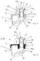
- Figures 1 to 4 each show a partial section of four different embodiments of the battery according to the invention.
- an accumulator according to the invention has an accumulator housing 1 on that with a side walls 1 a of the accumulator housing 1 overlapping Lid 2 is completed at the top.
- a pole sleeve 4 is provided in the cover 2 molded in its manufacture.
- pole sleeve 4 has on one of Circumferential grooves 5 surrounding fastening section 4a on. The grooves 5 are poured out with a plastic of the cover 2 to a gas and liquid-tight connection in the form of a labyrinth seal 6 between to form the cover 2 and the pole sleeve 4.
- the pole sleeve 4 is to form a connection pole 7 on one with an end plate 8 attached tubular pole shaft 9 connected to the accumulator. there the pole shaft 9 protrudes from the housing with a cap-like end 10 1 opposite end 4b of the pole sleeve 4 out.
- An outer jacket 7a Connection pole 7 is used to connect a consumer, for example by means of a pole terminal not shown.
- first cylindrical section 11 of the pole shaft 9 is provided, on which the connecting pole 7 gas and is sealed impermeable to liquids.
- first section 11 an electrically conductive connection of pole sleeve 4 and pole shaft 9 is provided.
- the first section 11 is followed by a transition region 12 in the direction increasing cross-section to the inside of the housing.
- a transition region 12 To the inside of the housing indicates the pole shaft 7 below the transition region 12 a cylindrical Area 14, to which a foot part 13 connects.
- the pole shaft 9 is fastened with the foot part 13 on the end plate 8 of the electrode.
- the diameter of the cylindrical region 14 is only small smaller than the inner diameter of the pole sleeve 4.
- the diameter of the cylindrical portion 11 is chosen so that around the cylindrical portion 11 and in the inner jacket 4c of the pole sleeve 4 Space 15 is formed, see Figure 3.
- the space 15 is at a Soldering process to create a gas and liquid-tight seal the connecting pole 7 to the outside and to produce an electrically conductive Connection between pole shaft 9 and pole sleeve 4 along the arrow a in the direction specified in Figure 2 filled with lead solder.
- the cylindrical area 14 and one of the pole sleeve 4 Surrounded area 13a of the foot part 13 at the transition to the cylindrical area 14 surrounded by a sliding element 16.
- the sliding element 16 is located seen radially between the regions 14, 13a of the pole shaft 7 and one this surrounding portion of the inner shell 4c of the pole sleeve 4.
- the tubular Sliding element 16 is made of a material that contributes to the frictional resistance between the parts to be brought together of pole sleeve 4 and To reduce pole shaft 9.
- the tubular sliding element 16 is in the pole sleeve 4 pinched.
- the cylindrical region 14 and that of the pole sleeve 4 Surrounded area 13a of the foot part 13 thus form a second section of the Pole shaft 7, in which the friction when sliding the pole sleeve 4 is reduced is.
- FIG. 2 shows an accumulator in which a sliding element is molded onto the hollow body-like shaft section 3 of the cover 2.
- the sliding element runs towards the upper end 4b of the pole sleeve 4 as a grommet-like insert 17, which forms a contact surface for the cylindrical region 14 and the region 13a of the foot part 13 of the pole shaft 9.
- the pole shaft 9 has a covering 18 which completely surrounds the cylindrical region 14 and partially surrounds the transition region 12. According to the invention, the coating 18 forms a contact surface for the inner jacket 4c of the pole sleeve.
- FIG. 4 shows, it is also provided within the scope of the invention to connect one serving as an insertion opening underside 4d of the pole sleeve 4 a circumferential, the To provide the inner diameter of the pole sleeve 4, bevel.
- a bevel is introduced into a plastic ring 19 such that it is surrounds the area 13a of the foot part 13 of the pole shaft 9.
- the plastic ring 19 serves as a sliding aid when the pole sleeve 4 and Pole shaft 9.
Landscapes
- Chemical & Material Sciences (AREA)
- Chemical Kinetics & Catalysis (AREA)
- Electrochemistry (AREA)
- General Chemical & Material Sciences (AREA)
- Engineering & Computer Science (AREA)
- Manufacturing & Machinery (AREA)
- Connection Of Batteries Or Terminals (AREA)
- Sealing Battery Cases Or Jackets (AREA)
- Supply Devices, Intensifiers, Converters, And Telemotors (AREA)
- Battery Mounting, Suspending (AREA)
- Exchange Systems With Centralized Control (AREA)
Applications Claiming Priority (2)
| Application Number | Priority Date | Filing Date | Title |
|---|---|---|---|
| DE10301043A DE10301043B3 (de) | 2003-01-13 | 2003-01-13 | Akkumulator mit Anschlusspol |
| DE10301043 | 2003-01-13 |
Publications (3)
| Publication Number | Publication Date |
|---|---|
| EP1453124A2 true EP1453124A2 (fr) | 2004-09-01 |
| EP1453124A3 EP1453124A3 (fr) | 2006-08-16 |
| EP1453124B1 EP1453124B1 (fr) | 2009-07-08 |
Family
ID=32185974
Family Applications (1)
| Application Number | Title | Priority Date | Filing Date |
|---|---|---|---|
| EP03027542A Expired - Lifetime EP1453124B1 (fr) | 2003-01-13 | 2003-11-29 | Borne terminale pour accumulateur |
Country Status (5)
| Country | Link |
|---|---|
| US (1) | US7517610B2 (fr) |
| EP (1) | EP1453124B1 (fr) |
| AT (1) | ATE436096T1 (fr) |
| DE (2) | DE10301043B3 (fr) |
| ES (1) | ES2329994T3 (fr) |
Cited By (1)
| Publication number | Priority date | Publication date | Assignee | Title |
|---|---|---|---|---|
| CN104813504A (zh) * | 2012-11-26 | 2015-07-29 | 江森自控汽车电池有限责任公司 | 用于蓄电池的连接极、蓄电池的极杆和蓄电池 |
Families Citing this family (10)
| Publication number | Priority date | Publication date | Assignee | Title |
|---|---|---|---|---|
| DE102005046256B4 (de) * | 2005-09-27 | 2010-09-30 | Vb Autobatterie Gmbh & Co. Kgaa | Bleibatterie und Kunststoff-Batteriedeckel hierzu |
| ES2275436B1 (es) * | 2005-11-18 | 2008-05-16 | Garcia Alberola E Hijos, S.L. | Terminales estancos para baterias. |
| EP2099084A1 (fr) * | 2008-03-06 | 2009-09-09 | Accumalux S.A. | Couvercle pour batteries à acide de plomb |
| DE102008029428A1 (de) | 2008-06-23 | 2009-12-24 | Iq Power Licensing Ag | Batteriedeckelkonstruktion mit Batteriepol |
| US20110206956A1 (en) * | 2010-02-22 | 2011-08-25 | Lineage Power Corporation | Round cell battery |
| DE102010033645B4 (de) * | 2010-08-06 | 2015-02-05 | Vb Autobatterie Gmbh & Co. Kgaa | Deckelteil für einen Akkumulator und Akkumulator mit einem solchen Deckelteil |
| CN102983303B (zh) * | 2012-12-17 | 2015-02-11 | 朱杰 | 改进的快速防腐式蓄电池接线装置 |
| EP3133674B1 (fr) | 2015-08-20 | 2017-11-22 | WEGMANN automotive GmbH & Co. KG | Douille de batterie avec protection antitorsion interne |
| KR102061293B1 (ko) * | 2015-12-23 | 2019-12-31 | 주식회사 엘지화학 | 이차전지 팩 |
| CN110518156B (zh) | 2019-10-23 | 2020-03-20 | 比亚迪股份有限公司 | 一种锂离子电池、电池模组、电池包及汽车 |
Family Cites Families (19)
| Publication number | Priority date | Publication date | Assignee | Title |
|---|---|---|---|---|
| US1960200A (en) * | 1931-02-12 | 1934-05-22 | Electric Storage Battery Co | Force feed grease seal for storage batteries |
| US3434883A (en) * | 1966-05-23 | 1969-03-25 | Bell Telephone Labor Inc | Cylindrical lead acid cell |
| US3652340A (en) * | 1969-12-29 | 1972-03-28 | Bell Telephone Labor Inc | Apparatus for and method of forming post seal for lead-acid cell |
| DE2535871A1 (de) * | 1975-08-12 | 1977-03-03 | Varta Batterie | Elektrischer akkumulator, insbesondere bleiakkumulator mit durch den deckel durchgefuehrtem abgedichtetem polbolzen |
| SE442155B (sv) * | 1977-02-11 | 1985-12-02 | Nordiska Ackumulator Fabriker | Polbultsgenomforing i locket till holjet hos en elektrisk ackumulator |
| US4164609A (en) * | 1978-05-08 | 1979-08-14 | Eltra Corporation | Battery post seal |
| SE7908222L (sv) * | 1979-10-04 | 1981-04-05 | Tudor Ab | Polgenomforing |
| US4331749A (en) * | 1980-11-14 | 1982-05-25 | Beck Jr Doyle | Storage battery structure |
| US4331748A (en) * | 1980-12-03 | 1982-05-25 | Hardigg Industries, Inc. | Sliding seal battery cover |
| GB2123205A (en) * | 1982-07-16 | 1984-01-25 | Allied Corp | Sliding battery post seal |
| US4495260A (en) * | 1983-04-07 | 1985-01-22 | Hardigg Industries, Inc. | Sliding seal lead bushing |
| DE3313419A1 (de) * | 1983-04-13 | 1984-10-25 | Peter J. 8623 Staffelstein Moll | Zelle fuer einen elektrischen akkumulator mit einer zellendeckel-polabdichtung |
| JPS6196660A (ja) * | 1984-10-17 | 1986-05-15 | Matsushita Electric Ind Co Ltd | 鉛蓄電池 |
| US4775604A (en) * | 1986-05-08 | 1988-10-04 | Globe-Union Inc. | Method and apparatus for sealing a battery terminal post |
| US4859547A (en) * | 1987-10-06 | 1989-08-22 | Gates Energy Products, Inc. | Battery terminal and method |
| US5273845A (en) * | 1992-08-18 | 1993-12-28 | Acme Electric Corporation | Terminal structure and seal |
| US5905002A (en) * | 1997-02-13 | 1999-05-18 | Gnb Technologies, Inc. | Lead acid storage battery |
| JP3601248B2 (ja) * | 1997-04-22 | 2004-12-15 | 松下電器産業株式会社 | 密閉型鉛蓄電池およびその製造法 |
| JPH10321199A (ja) * | 1997-05-22 | 1998-12-04 | Miyagawa Kasei Ind Co Ltd | 鉛ブッシングおよび該鉛ブッシングを備えた鉛蓄電池 |
-
2003
- 2003-01-13 DE DE10301043A patent/DE10301043B3/de not_active Expired - Fee Related
- 2003-11-29 EP EP03027542A patent/EP1453124B1/fr not_active Expired - Lifetime
- 2003-11-29 DE DE50311683T patent/DE50311683D1/de not_active Expired - Lifetime
- 2003-11-29 ES ES03027542T patent/ES2329994T3/es not_active Expired - Lifetime
- 2003-11-29 AT AT03027542T patent/ATE436096T1/de active
-
2004
- 2004-01-12 US US10/755,717 patent/US7517610B2/en not_active Expired - Lifetime
Cited By (2)
| Publication number | Priority date | Publication date | Assignee | Title |
|---|---|---|---|---|
| CN104813504A (zh) * | 2012-11-26 | 2015-07-29 | 江森自控汽车电池有限责任公司 | 用于蓄电池的连接极、蓄电池的极杆和蓄电池 |
| CN104813504B (zh) * | 2012-11-26 | 2017-12-26 | 江森自控汽车电池有限责任公司 | 用于蓄电池的连接极、蓄电池的极杆和蓄电池 |
Also Published As
| Publication number | Publication date |
|---|---|
| DE50311683D1 (de) | 2009-08-20 |
| ATE436096T1 (de) | 2009-07-15 |
| EP1453124A3 (fr) | 2006-08-16 |
| US20040170892A1 (en) | 2004-09-02 |
| DE10301043B3 (de) | 2004-05-27 |
| US7517610B2 (en) | 2009-04-14 |
| EP1453124B1 (fr) | 2009-07-08 |
| ES2329994T3 (es) | 2009-12-03 |
Similar Documents
| Publication | Publication Date | Title |
|---|---|---|
| DE69027846T2 (de) | Verbindungsanordnung zur zufuhr bei implantierbarer ärztlichen vorrichtung | |
| DE2309204C2 (de) | Steckvorrichtung für den Anschluß einer Anzahl von Zuleitungen für Herzelektroden an einen Herzschrittmacher | |
| EP1617517B1 (fr) | Connexion entre une extremité de câble et une borne | |
| DE10301043B3 (de) | Akkumulator mit Anschlusspol | |
| EP2272134B1 (fr) | Connecteur pour etablir le contact d' une carte a circuits imprimes electriques disposee dans un boitier | |
| DE2809886A1 (de) | Elektrische steckverbindung | |
| DE102007012124A1 (de) | Kompressionsverbinder für Koaxialkabel | |
| EP2617104A1 (fr) | Contact électrique | |
| DE102009017514A1 (de) | Knopfzelle ohne Bördelung | |
| DE102005059754B4 (de) | Spritzgussgeformte Außenkonusdurchführung | |
| DE102013105669A1 (de) | Verbindung eines elektrischen Kabels mit einem Kontaktteil | |
| DE68921744T2 (de) | Durchführungsstecker für eine implantierbare medizinische vorrichtung. | |
| WO2016155861A1 (fr) | Dispositif de connexion enfichable et procédé de fabrication d'un dispositif de connexion enfichable | |
| EP2486954B1 (fr) | Passage de contact dans des composants électroniques | |
| DE2936220C2 (fr) | ||
| DE4425421C1 (de) | Isolierkörper für Kabelendgarnituren, insbesondere Kabelstecker | |
| EP2954928B1 (fr) | Passage de conduite et unité de fonctionnement électrique | |
| DE3032187A1 (de) | Geschlossener kondensator | |
| DE102010033645B4 (de) | Deckelteil für einen Akkumulator und Akkumulator mit einem solchen Deckelteil | |
| DE2624334B2 (de) | Elektrischer Wickelkondensator | |
| EP0651918B1 (fr) | Corps isolant et etanche deformable elastiquement pour connecteur de cables et analogue | |
| DE102007004896B4 (de) | Baueinheit aus einem Gehäusekörper mit Durchführung zur Aufnahme eines Anschlusskabels sowie vorkonfektioniertes Anschlusskabel für eine derartige Baueinheit und Montageverfahren hierfür | |
| DE2056378B2 (de) | Anschlußteil für elektrische Vorrichtungen mit einem elektrisch leitenden Niet | |
| DE2651703A1 (de) | Kabeldurchfuehrung mit manschette, dielektrischem koerper und leiter | |
| DE3616991A1 (de) | Kondensator |
Legal Events
| Date | Code | Title | Description |
|---|---|---|---|
| PUAI | Public reference made under article 153(3) epc to a published international application that has entered the european phase |
Free format text: ORIGINAL CODE: 0009012 |
|
| AK | Designated contracting states |
Kind code of ref document: A2 Designated state(s): AT BE BG CH CY CZ DE DK EE ES FI FR GB GR HU IE IT LI LU MC NL PT RO SE SI SK TR |
|
| AX | Request for extension of the european patent |
Extension state: AL LT LV MK |
|
| RAP1 | Party data changed (applicant data changed or rights of an application transferred) |
Owner name: VB AUTOBATTERIE GMBH & CO. KGAA. |
|
| PUAL | Search report despatched |
Free format text: ORIGINAL CODE: 0009013 |
|
| AK | Designated contracting states |
Kind code of ref document: A3 Designated state(s): AT BE BG CH CY CZ DE DK EE ES FI FR GB GR HU IE IT LI LU MC NL PT RO SE SI SK TR |
|
| AX | Request for extension of the european patent |
Extension state: AL LT LV MK |
|
| RIC1 | Information provided on ipc code assigned before grant |
Ipc: H01M 2/06 20060101AFI20060712BHEP |
|
| 17P | Request for examination filed |
Effective date: 20061106 |
|
| 17Q | First examination report despatched |
Effective date: 20070125 |
|
| AKX | Designation fees paid |
Designated state(s): AT BE BG CH CY CZ DE DK EE ES FI FR GB GR HU IE IT LI LU MC NL PT RO SE SI SK TR |
|
| GRAP | Despatch of communication of intention to grant a patent |
Free format text: ORIGINAL CODE: EPIDOSNIGR1 |
|
| GRAS | Grant fee paid |
Free format text: ORIGINAL CODE: EPIDOSNIGR3 |
|
| GRAA | (expected) grant |
Free format text: ORIGINAL CODE: 0009210 |
|
| AK | Designated contracting states |
Kind code of ref document: B1 Designated state(s): AT BE BG CH CY CZ DE DK EE ES FI FR GB GR HU IE IT LI LU MC NL PT RO SE SI SK TR |
|
| REG | Reference to a national code |
Ref country code: GB Ref legal event code: FG4D Free format text: NOT ENGLISH |
|
| REG | Reference to a national code |
Ref country code: CH Ref legal event code: EP |
|
| REG | Reference to a national code |
Ref country code: IE Ref legal event code: FG4D |
|
| REF | Corresponds to: |
Ref document number: 50311683 Country of ref document: DE Date of ref document: 20090820 Kind code of ref document: P |
|
| PG25 | Lapsed in a contracting state [announced via postgrant information from national office to epo] |
Ref country code: SI Free format text: LAPSE BECAUSE OF FAILURE TO SUBMIT A TRANSLATION OF THE DESCRIPTION OR TO PAY THE FEE WITHIN THE PRESCRIBED TIME-LIMIT Effective date: 20090708 |
|
| NLV1 | Nl: lapsed or annulled due to failure to fulfill the requirements of art. 29p and 29m of the patents act | ||
| REG | Reference to a national code |
Ref country code: ES Ref legal event code: FG2A Ref document number: 2329994 Country of ref document: ES Kind code of ref document: T3 |
|
| PG25 | Lapsed in a contracting state [announced via postgrant information from national office to epo] |
Ref country code: FI Free format text: LAPSE BECAUSE OF FAILURE TO SUBMIT A TRANSLATION OF THE DESCRIPTION OR TO PAY THE FEE WITHIN THE PRESCRIBED TIME-LIMIT Effective date: 20090708 |
|
| REG | Reference to a national code |
Ref country code: IE Ref legal event code: FD4D |
|
| PG25 | Lapsed in a contracting state [announced via postgrant information from national office to epo] |
Ref country code: NL Free format text: LAPSE BECAUSE OF FAILURE TO SUBMIT A TRANSLATION OF THE DESCRIPTION OR TO PAY THE FEE WITHIN THE PRESCRIBED TIME-LIMIT Effective date: 20090708 |
|
| PG25 | Lapsed in a contracting state [announced via postgrant information from national office to epo] |
Ref country code: PT Free format text: LAPSE BECAUSE OF FAILURE TO SUBMIT A TRANSLATION OF THE DESCRIPTION OR TO PAY THE FEE WITHIN THE PRESCRIBED TIME-LIMIT Effective date: 20091109 Ref country code: BG Free format text: LAPSE BECAUSE OF FAILURE TO SUBMIT A TRANSLATION OF THE DESCRIPTION OR TO PAY THE FEE WITHIN THE PRESCRIBED TIME-LIMIT Effective date: 20091008 |
|
| PG25 | Lapsed in a contracting state [announced via postgrant information from national office to epo] |
Ref country code: RO Free format text: LAPSE BECAUSE OF FAILURE TO SUBMIT A TRANSLATION OF THE DESCRIPTION OR TO PAY THE FEE WITHIN THE PRESCRIBED TIME-LIMIT Effective date: 20090708 Ref country code: CZ Free format text: LAPSE BECAUSE OF FAILURE TO SUBMIT A TRANSLATION OF THE DESCRIPTION OR TO PAY THE FEE WITHIN THE PRESCRIBED TIME-LIMIT Effective date: 20090708 Ref country code: DK Free format text: LAPSE BECAUSE OF FAILURE TO SUBMIT A TRANSLATION OF THE DESCRIPTION OR TO PAY THE FEE WITHIN THE PRESCRIBED TIME-LIMIT Effective date: 20090708 Ref country code: EE Free format text: LAPSE BECAUSE OF FAILURE TO SUBMIT A TRANSLATION OF THE DESCRIPTION OR TO PAY THE FEE WITHIN THE PRESCRIBED TIME-LIMIT Effective date: 20090708 Ref country code: IE Free format text: LAPSE BECAUSE OF FAILURE TO SUBMIT A TRANSLATION OF THE DESCRIPTION OR TO PAY THE FEE WITHIN THE PRESCRIBED TIME-LIMIT Effective date: 20090708 |
|
| PLBE | No opposition filed within time limit |
Free format text: ORIGINAL CODE: 0009261 |
|
| STAA | Information on the status of an ep patent application or granted ep patent |
Free format text: STATUS: NO OPPOSITION FILED WITHIN TIME LIMIT |
|
| BERE | Be: lapsed |
Owner name: VB AUTOBATTERIE G.M.B.H. & CO. KGAA Effective date: 20091130 |
|
| PG25 | Lapsed in a contracting state [announced via postgrant information from national office to epo] |
Ref country code: SK Free format text: LAPSE BECAUSE OF FAILURE TO SUBMIT A TRANSLATION OF THE DESCRIPTION OR TO PAY THE FEE WITHIN THE PRESCRIBED TIME-LIMIT Effective date: 20090708 |
|
| 26N | No opposition filed |
Effective date: 20100409 |
|
| PG25 | Lapsed in a contracting state [announced via postgrant information from national office to epo] |
Ref country code: MC Free format text: LAPSE BECAUSE OF NON-PAYMENT OF DUE FEES Effective date: 20091130 |
|
| REG | Reference to a national code |
Ref country code: CH Ref legal event code: PL |
|
| GBPC | Gb: european patent ceased through non-payment of renewal fee |
Effective date: 20091129 |
|
| PG25 | Lapsed in a contracting state [announced via postgrant information from national office to epo] |
Ref country code: GR Free format text: LAPSE BECAUSE OF FAILURE TO SUBMIT A TRANSLATION OF THE DESCRIPTION OR TO PAY THE FEE WITHIN THE PRESCRIBED TIME-LIMIT Effective date: 20091009 Ref country code: LI Free format text: LAPSE BECAUSE OF NON-PAYMENT OF DUE FEES Effective date: 20091130 Ref country code: BE Free format text: LAPSE BECAUSE OF NON-PAYMENT OF DUE FEES Effective date: 20091130 Ref country code: CH Free format text: LAPSE BECAUSE OF NON-PAYMENT OF DUE FEES Effective date: 20091130 |
|
| PG25 | Lapsed in a contracting state [announced via postgrant information from national office to epo] |
Ref country code: GB Free format text: LAPSE BECAUSE OF NON-PAYMENT OF DUE FEES Effective date: 20091129 |
|
| PG25 | Lapsed in a contracting state [announced via postgrant information from national office to epo] |
Ref country code: LU Free format text: LAPSE BECAUSE OF NON-PAYMENT OF DUE FEES Effective date: 20091129 |
|
| PG25 | Lapsed in a contracting state [announced via postgrant information from national office to epo] |
Ref country code: HU Free format text: LAPSE BECAUSE OF FAILURE TO SUBMIT A TRANSLATION OF THE DESCRIPTION OR TO PAY THE FEE WITHIN THE PRESCRIBED TIME-LIMIT Effective date: 20100109 |
|
| PG25 | Lapsed in a contracting state [announced via postgrant information from national office to epo] |
Ref country code: TR Free format text: LAPSE BECAUSE OF FAILURE TO SUBMIT A TRANSLATION OF THE DESCRIPTION OR TO PAY THE FEE WITHIN THE PRESCRIBED TIME-LIMIT Effective date: 20090708 |
|
| PG25 | Lapsed in a contracting state [announced via postgrant information from national office to epo] |
Ref country code: CY Free format text: LAPSE BECAUSE OF FAILURE TO SUBMIT A TRANSLATION OF THE DESCRIPTION OR TO PAY THE FEE WITHIN THE PRESCRIBED TIME-LIMIT Effective date: 20090708 |
|
| PG25 | Lapsed in a contracting state [announced via postgrant information from national office to epo] |
Ref country code: SE Free format text: LAPSE BECAUSE OF FAILURE TO SUBMIT A TRANSLATION OF THE DESCRIPTION OR TO PAY THE FEE WITHIN THE PRESCRIBED TIME-LIMIT Effective date: 20090708 |
|
| PGFP | Annual fee paid to national office [announced via postgrant information from national office to epo] |
Ref country code: FR Payment date: 20131118 Year of fee payment: 11 Ref country code: AT Payment date: 20131101 Year of fee payment: 11 |
|
| PGFP | Annual fee paid to national office [announced via postgrant information from national office to epo] |
Ref country code: ES Payment date: 20131126 Year of fee payment: 11 Ref country code: IT Payment date: 20131126 Year of fee payment: 11 |
|
| REG | Reference to a national code |
Ref country code: DE Ref legal event code: R082 Ref document number: 50311683 Country of ref document: DE Representative=s name: MEISSNER, BOLTE & PARTNER GBR, DE Ref country code: DE Ref legal event code: R082 Ref document number: 50311683 Country of ref document: DE Representative=s name: MEISSNER BOLTE PATENTANWAELTE RECHTSANWAELTE P, DE |
|
| REG | Reference to a national code |
Ref country code: AT Ref legal event code: MM01 Ref document number: 436096 Country of ref document: AT Kind code of ref document: T Effective date: 20141129 |
|
| REG | Reference to a national code |
Ref country code: FR Ref legal event code: ST Effective date: 20150731 |
|
| PG25 | Lapsed in a contracting state [announced via postgrant information from national office to epo] |
Ref country code: AT Free format text: LAPSE BECAUSE OF NON-PAYMENT OF DUE FEES Effective date: 20141129 |
|
| PG25 | Lapsed in a contracting state [announced via postgrant information from national office to epo] |
Ref country code: FR Free format text: LAPSE BECAUSE OF NON-PAYMENT OF DUE FEES Effective date: 20141201 |
|
| REG | Reference to a national code |
Ref country code: ES Ref legal event code: FD2A Effective date: 20151229 |
|
| PG25 | Lapsed in a contracting state [announced via postgrant information from national office to epo] |
Ref country code: IT Free format text: LAPSE BECAUSE OF NON-PAYMENT OF DUE FEES Effective date: 20141129 |
|
| PG25 | Lapsed in a contracting state [announced via postgrant information from national office to epo] |
Ref country code: ES Free format text: LAPSE BECAUSE OF NON-PAYMENT OF DUE FEES Effective date: 20141130 |
|
| REG | Reference to a national code |
Ref country code: DE Ref legal event code: R082 Ref document number: 50311683 Country of ref document: DE Representative=s name: MEISSNER BOLTE PATENTANWAELTE RECHTSANWAELTE P, DE |
|
| REG | Reference to a national code |
Ref country code: DE Ref legal event code: R079 Ref document number: 50311683 Country of ref document: DE Free format text: PREVIOUS MAIN CLASS: H01M0002300000 Ipc: H01M0050543000 |
|
| REG | Reference to a national code |
Ref country code: DE Ref legal event code: R082 Ref document number: 50311683 Country of ref document: DE Representative=s name: MEISSNER BOLTE PATENTANWAELTE RECHTSANWAELTE P, DE Ref country code: DE Ref legal event code: R081 Ref document number: 50311683 Country of ref document: DE Owner name: CLARIOS GERMANY GMBH & CO. KGAA, DE Free format text: FORMER OWNER: VB AUTOBATTERIE GMBH & CO. KGAA, 30419 HANNOVER, DE |
|
| PGFP | Annual fee paid to national office [announced via postgrant information from national office to epo] |
Ref country code: DE Payment date: 20221125 Year of fee payment: 20 |
|
| REG | Reference to a national code |
Ref country code: DE Ref legal event code: R071 Ref document number: 50311683 Country of ref document: DE |