EP1452878A1 - Electric current sensor - Google Patents
Electric current sensor Download PDFInfo
- Publication number
- EP1452878A1 EP1452878A1 EP03004186A EP03004186A EP1452878A1 EP 1452878 A1 EP1452878 A1 EP 1452878A1 EP 03004186 A EP03004186 A EP 03004186A EP 03004186 A EP03004186 A EP 03004186A EP 1452878 A1 EP1452878 A1 EP 1452878A1
- Authority
- EP
- European Patent Office
- Prior art keywords
- magnetic
- core
- housing
- sensor according
- magnetic circuit
- Prior art date
- Legal status (The legal status is an assumption and is not a legal conclusion. Google has not performed a legal analysis and makes no representation as to the accuracy of the status listed.)
- Withdrawn
Links
Images


Classifications
-
- G—PHYSICS
- G01—MEASURING; TESTING
- G01R—MEASURING ELECTRIC VARIABLES; MEASURING MAGNETIC VARIABLES
- G01R15/00—Details of measuring arrangements of the types provided for in groups G01R17/00 - G01R29/00, G01R33/00 - G01R33/26 or G01R35/00
- G01R15/14—Adaptations providing voltage or current isolation, e.g. for high-voltage or high-current networks
- G01R15/20—Adaptations providing voltage or current isolation, e.g. for high-voltage or high-current networks using galvano-magnetic devices, e.g. Hall-effect devices, i.e. measuring a magnetic field via the interaction between a current and a magnetic field, e.g. magneto resistive or Hall effect devices
- G01R15/207—Constructional details independent of the type of device used
-
- G—PHYSICS
- G01—MEASURING; TESTING
- G01R—MEASURING ELECTRIC VARIABLES; MEASURING MAGNETIC VARIABLES
- G01R15/00—Details of measuring arrangements of the types provided for in groups G01R17/00 - G01R29/00, G01R33/00 - G01R33/26 or G01R35/00
- G01R15/14—Adaptations providing voltage or current isolation, e.g. for high-voltage or high-current networks
- G01R15/20—Adaptations providing voltage or current isolation, e.g. for high-voltage or high-current networks using galvano-magnetic devices, e.g. Hall-effect devices, i.e. measuring a magnetic field via the interaction between a current and a magnetic field, e.g. magneto resistive or Hall effect devices
- G01R15/205—Adaptations providing voltage or current isolation, e.g. for high-voltage or high-current networks using galvano-magnetic devices, e.g. Hall-effect devices, i.e. measuring a magnetic field via the interaction between a current and a magnetic field, e.g. magneto resistive or Hall effect devices using magneto-resistance devices, e.g. field plates
Definitions
- the present invention relates to an electric current sensor, in particular an open loop electric current sensor.
- the circuit magnetic is typically made of a conductive material of magnetic flux, says “magnetic material”, laminated.
- Hall cell can have bounds electrical in the form of pins orthogonally mounted on a circuit printed.
- an object of the invention is to provide a robust, precise and economical electrical current sensor to manufacture.
- an electric current sensor comprising a housing, a magnetic circuit comprising a core magnetic material and a magnetic field detector comprising a detection cell arranged in an air gap of the magnetic circuit.
- the the sensor may further comprise a connector part having terminals for connection in order to be able to connect the sensor to a processing unit measurement signals from the magnetic field detector.
- the sensor may have a central opening corresponding to the opening formed by the magnetic circuit so that a conductor, such as an electrical cable leading the electric current to be measured can pass through the magnetic circuit.
- the housing may further include a support wall extending from the central opening for fixing the sensor to a cable or conductor electric.
- the magnetic circuit of the sensor includes a flange rigidly fixed, preferably by welding, to the core magnetic on both sides of the air gap, the flange being made of a material mechanical more resistant than the material of the magnetic core.
- the core magnetic may be of a soft non-laminated magnetic material, such as a FeNi alloy.
- the magnetic circuit can advantageously undergo an operation annealing after welding of the flange to obtain the magnetic properties circuits.
- the flange can also be provided with an anti-rotation element, in the form of a shoulder or a tongue, in order to avoid rotation of the circuit magnetic in the case resulting from vibrations during its use or during of its manufacture, in particular during an ultrasonic welding operation of a cover to the housing to guarantee its tightness. This ensures that the magnetic circuit does not apply excessive stress on the cell magnetic detection.
- the flange guarantees a predefined length and constant air gap and make the sensor more impact resistant mechanical and stresses due to the relative thermal expansion between the magnetic core and other components in contact with the core magnetic, such as the case.
- This solution also allows a more great freedom in choosing magnetic materials and reducing the amount of the material forming the magnetic core.
- Welding the flange to the core is particularly advantageous since the welding operation can be automated and cutting operations on the magnetic core can be avoided.
- the flange can advantageously be formed from metal sheet formed and stamped.
- the magnetic core can advantageously be formed from a wire of material full magnetic undergoing shearing and bending, which are relatively simple operations, easy to automate and not entraining no loss of material.
- the magnetic field detector comprises a detection cell mounted by surface welding on a support plate, for example a printed circuit plate, the plate comprising a notch intended for the insertion of one end of the core of the magnetic circuit, so that only the detection cell is inserted in the air gap.
- a support plate for example a printed circuit plate
- the plate comprising a notch intended for the insertion of one end of the core of the magnetic circuit, so that only the detection cell is inserted in the air gap.
- SMD Surface Mount Device
- the notch can also be used as a reference surface for positioning the magnetic circuit relative to the detection cell.
- This configuration also allows axial mounting, that is to say essentially orthogonal to the median plane of the magnetic circuit, of the various components, in particular the magnetic field detector, the magnetic circuit, the cover and the housing.
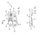
- a current sensor 1 comprises a housing 2, a cover 3, a magnetic circuit 4, a magnetic field detector 5 and connection terminals 6.
- the housing 2 comprises a connector part 7, a fixing part or support 8 and a body part 9 defining a housing 10 in which the magnetic circuit 4 and the magnetic field detector 5 are mounted:
- the cover 3 is intended to close the open side 11 of the body part 9, the body part being provided with a rim 11 in which is housed, so contiguous, a complementary rim 12 of the cover 3.
- the body part 9 is provided with a central opening 13 intended to be crossed by a conductor in which the current to be measured flows.
- the conductor can in particular be a cable, for example the automotive battery power cable, the sensor providing information to a battery management and control system.
- the part of support or fixing 8 in the form of a curved wall extending in a axial direction, i.e. in a direction essentially orthogonal to the median plane of the magnetic circuit, used to fix the sensor to the cable by a band enclosing the cable and the fixing part 8.
- the fixing part 8, the body part 9 and connector part 7 of the housing can be formed in one piece, for example of injected plastic.
- connection 6 can be in the form of inserted connection tabs in a direction D essentially orthogonal to the axial direction A in holes or passages 14 provided for this purpose in the housing.
- the terminals of connection include ends in the form of pins 15 which are inserted with interference into metallized holes 16 of the field detector magnetic. Connection terminals 6 are therefore used to connect the sensor current to an external measurement signal processing unit.
- the magnetic circuit 4 comprises a core which, in this example, is under shape of a torus 17 provided with a gap 18 formed between the free ends 19, 20 of the nucleus.
- the core 17 is made of a solid magnetic material, that is to say non-laminated, the magnetic material being for example FeNi, which conducts magnetic flux well with low hysteresis, but which is a poor electrical conductor, in order to reduce losses due to Foucault.
- the essentially circular section of the core and its non-laminated construction allow the core to be made from a wire of material sheared in desired length and formed by relatively simple manufacturing steps and without loss of material.
- the magnetic circuit further comprises a flange 21 made of a non-magnetic material and stronger than the core material.
- the flange 21 can advantageously be made of stainless steel sheets (or other non-magnetic metals) by forming and stamping.
- the flange 21 has parts of attachment 22 in the form of lugs intended to be welded to the core 17 of on either side of the air gap 18.
- the ends 19, 20, of the core 17 are pressed against a reference block of which the thickness corresponds to the desired air gap length.
- the magnetic circuit is annealed at a temperature allowing to obtain the optimal magnetic properties of the magnetic core.
- the bridle advantageously makes it possible to maintain the dimensions of the air gap during this operation.
- the flange 21 may advantageously include an anti-rotation element, by free in the form of a tongue 23 which serves to prevent rotation of the magnetic circuit with respect to the support plate.
- the tongue 23 abuts against the support plate 26.
- the rotation of the circuit magnetic can intervene during ultrasonic welding processes, especially tors welding of the cover to the housing by ultrasound.
- the ultrasonic welding of the cover to the housing ensures good sealing of the interface 11, 12 between the cover and the housing.
- the magnetic field detector comprises a detection cell 25 and a support plate 26 on which the detection cell is mounted.
- the support plate 26 may be a printed circuit having conductive traces 27 for the interconnection of the detection cell to the connection terminals 6 of the connector part. Electronic components 28 can also be mounted on the support plate.
- the detection cell 25 is provided with connection lugs 29 allowing the connection by surface welding (so-called "SMD" technology (Surface Mount Device)). This surface mounting method makes it possible to automate the mounting of the cell on the support plate and to obtain very good mounting and positioning precision of the cell with respect to the support plate.
- the support plate has a notch 30 in which is housed one end 19 of the magnetic circuit, thus allowing the insertion of the detection cell 25 alone in the air gap 17.
- the notch 30 comprises positioning surfaces 37, 38, 39 serving as reference surfaces for positioning the magnetic circuit with respect to the magnetic field detector and in particular with respect to the detection cell 25.
- the support plate 26 is mounted and oriented in an axial plane, that is to say essentially orthogonally to the median plane of the magnetic core.
- the housing is provided with axial rails 31, 32, in which the opposite lateral edges 33, 34 of the support plate are inserted and held.
- the connection terminals 6 are inserted in the corresponding holes 14, of the housing and the pins 15 inserted in force in the metallized holes 16.
- the magnetic circuit 4 as well as the cover 12 are also mounted axially in, respectively on, the housing, thus simplifying the steps of assembling the sensor.
- the bottom of the housing 10 of the housing body as well as the inner surface of the cover may be provided with protrusions 35, 36 bearing against the core of the magnetic circuit to hold it without play between the cover and the housing.
- the surface of the protrusions in support takes part in the rounded shape of the surface of the core.
- the magnetic circuit is by these means well held in the housing.
- One of the advantages of the aforementioned fixing means is that they allow a natural positioning of the magnetic circuit in the housing relative to the support plate 26, in particular of one end of the magnetic circuit in notch 30.
- the welding of a flange on the core of the magnetic circuit on either side of the air gap can be performed in an automated step and ensures that the length of the air gap is maintained at a determined value and essentially constant even in the presence of original constraints thermal or mechanical.
- the sensor is shock and force resistant resulting inertia which could cause permanent deformation of the core in the absence of the flange.
- An advantageous consequence is that the magnetic circuits can be stored and transported in bulk, reducing handling costs.
- the presence of the flange allows the use of materials for the core which are optimized for their magnetic properties, regardless of the mechanical resistance of the core.
- a core formed of a solid wire which is relatively inexpensive to manufacture and which can be sheared without loss of materials. Welding the flange on the magnetic core can easily be performed in an automated process and not requiring any other cutting operation on the magnetic core.
Landscapes
- Physics & Mathematics (AREA)
- General Physics & Mathematics (AREA)
- Measuring Instrument Details And Bridges, And Automatic Balancing Devices (AREA)
- Measurement Of Current Or Voltage (AREA)
- Glass Compositions (AREA)
- Electron Sources, Ion Sources (AREA)
- Investigating Or Analyzing Materials By The Use Of Electric Means (AREA)
- Transmission And Conversion Of Sensor Element Output (AREA)
Abstract
Description
La présente invention concerne un capteur de courant électrique, notamment un capteur de courant électrique à boucle ouverte.The present invention relates to an electric current sensor, in particular an open loop electric current sensor.
Il existe de nombreux capteurs de courant à boucle ouverte comprenant un circuit magnétique ayant un entrefer et une cellule de Hall disposée dans l'entrefer pour mesurer le champ magnétique induit par un courant électrique circulant dans un conducteur traversant le circuit magnétique. Le circuit magnétique est typiquement en un matériau conducteur de flux magnétique, dit "matériau magnétique", feuilleté. La cellule de Hall peut avoir des bornes électriques sous forme de broches montées orthogonalement sur un circuit imprimé.There are many open loop current sensors including a magnetic circuit having an air gap and a Hall cell arranged in the air gap to measure the magnetic field induced by an electric current circulating in a conductor crossing the magnetic circuit. The circuit magnetic is typically made of a conductive material of magnetic flux, says "magnetic material", laminated. Hall cell can have bounds electrical in the form of pins orthogonally mounted on a circuit printed.
Les capteurs à boucle ouverte conventionnels du type précité sont relativement onéreux à fabriquer en raison du coût de fabrication des circuits magnétiques feuilletés et des coûts d'assemblage des différents composants, notamment de la cellule Hall et du circuit magnétique dans un boítier, ceci en respectant les dimensions et les tolérances de l'entrefer et de la position de la cellule Hall pour une bonne précision de mesure.Conventional open loop sensors of the aforementioned type are relatively expensive to manufacture due to the cost of manufacturing magnetic circuits laminated and assembly costs of the various components, in particular the Hall cell and the magnetic circuit in a box, this respecting the dimensions and tolerances of the air gap and the position of the Hall cell for good measurement accuracy.
Un autre problème des capteurs de courant à boucle ouverte conventionnels est qu'ils ne sont pas suffisamment robustes pour certaines applications, par exemple dans le domaine automobile où les composants doivent pouvoir supporter des chocs et des vibrations sans perte de précision de mesure. Dans certaines applications, où le capteur de courant doit être résistant à l'environnement et étanche, le circuit magnétique ainsi que la cellule Hall sont couverts par une résine. Ceci peut néanmoins avoir des conséquences néfastes sur la précision de mesure en raison des différents coefficients de dilatation, notamment thermiques et/ou d'humidité, du circuit magnétique, de la résine et/ou du boítier, conduisant à l'application de contraintes mécaniques sur le circuit magnétique. La variation de l'entrefer due à ces contraintes induit des erreurs dans la mesure de l'induction magnétique et donc sur la mesure du courant électrique.Another problem with conventional open loop current sensors is that they are not robust enough for certain applications, for example in the automotive field where components must be able withstand shock and vibration without loss of measurement accuracy. In some applications where the current sensor must be resistant to environment and waterproof, the magnetic circuit and the Hall cell are covered by a resin. This can however have consequences detrimental to the measurement accuracy due to the different coefficients of expansion, in particular thermal and / or humidity, of the magnetic circuit, of the resin and / or housing, leading to the application of mechanical stress on the magnetic circuit. The variation in the air gap due to these constraints induces errors in the measurement of magnetic induction and therefore on the measurement of Electric power.
Au vu des inconvénients précités, un but de l'invention est de réaliser un capteur de courant électrique robuste, précis et économe à fabriquer.In view of the aforementioned drawbacks, an object of the invention is to provide a robust, precise and economical electrical current sensor to manufacture.
Il est avantageux de réaliser un capteur de courant comprenant peu de composants pouvant être assemblés par des étapes d'assemblage relativement simples et adaptées à l'automatisation.It is advantageous to produce a current sensor comprising few components that can be assembled by assembly steps relatively simple and suitable for automation.
Il est avantageux de réaliser un capteur de courant résistant à l'environnement et pouvant subir d'importantes variations de température sans perte notable de précision.It is advantageous to make an environment-resistant current sensor and which can undergo significant temperature variations without significant loss of precision.
Il est avantageux pour certaines applications de réaliser un capteur de courant apte à mesurer les courants électriques dans des câbles ou autres conducteurs électriques de grande section.It is advantageous for certain applications to produce a current sensor suitable for measuring electric currents in cables or other conductors large section electrics.
Des buts de l'invention sont réalisés par le capteur de courant selon la
revendication 1 ou selon la revendication 7.Objects of the invention are achieved by the current sensor according to the
claim 1 or according to
Dans la présente demande, un capteur de courant électrique est décrit, le capteur comportant un boítier, un circuit magnétique comprenant un noyau en matériau magnétique et un détecteur de champ magnétique comprenant une cellule de détection disposée dans un entrefer du circuit magnétique. Le capteur peut en outre comporter une partie connecteur ayant des bornes de connexion afin de pouvoir connecter le capteur à une unité de traitement des signaux de mesure provenant du détecteur de champ magnétique. Le capteur peut avoir une ouverture centrale correspondant à l'ouverture formée par le circuit magnétique pour qu'un conducteur, tel qu'un câble électrique conduisant le courant électrique à mesurer, puisse traverser le circuit magnétique. Le boítier peut en outre comprendre une paroi de support s'étendant depuis l'ouverture centrale pour la fixation du capteur à un câble ou conducteur électrique.In the present application, an electric current sensor is described, the sensor comprising a housing, a magnetic circuit comprising a core magnetic material and a magnetic field detector comprising a detection cell arranged in an air gap of the magnetic circuit. The the sensor may further comprise a connector part having terminals for connection in order to be able to connect the sensor to a processing unit measurement signals from the magnetic field detector. The sensor may have a central opening corresponding to the opening formed by the magnetic circuit so that a conductor, such as an electrical cable leading the electric current to be measured can pass through the magnetic circuit. The housing may further include a support wall extending from the central opening for fixing the sensor to a cable or conductor electric.
Selon un premier aspect de l'invention, le circuit magnétique du capteur comprend une bride fixée rigidement, de préférence par soudage, au noyau magnétique de part et d'autre de l'entrefer, la bride étant en un matériau mécanique plus résistant que le matériau du noyau magnétique. Le noyau magnétique peut être en un matériau magnétique doux non-feuilleté, tel qu'un alliage FeNi. Le circuit magnétique peut avantageusement subir une opération de recuit après soudage de la bride pour obtenir les propriétés magnétiques optimales du circuit. La bride peut en outre être munie d'un élément anti-rotation, sous forme d'épaule ou de languette, afin d'éviter la rotation du circuit magnétique dans le boítier résultant de vibrations lors de son utilisation ou lors de sa fabrication, notamment lors d'une opération de soudage par ultrason d'un couvercle au boítier afin de garantir son étanchéité. Ceci permet d'assurer que le circuit magnétique n'applique pas par de contraintes excessives sur la cellule de détection magnétique.According to a first aspect of the invention, the magnetic circuit of the sensor includes a flange rigidly fixed, preferably by welding, to the core magnetic on both sides of the air gap, the flange being made of a material mechanical more resistant than the material of the magnetic core. The core magnetic may be of a soft non-laminated magnetic material, such as a FeNi alloy. The magnetic circuit can advantageously undergo an operation annealing after welding of the flange to obtain the magnetic properties circuits. The flange can also be provided with an anti-rotation element, in the form of a shoulder or a tongue, in order to avoid rotation of the circuit magnetic in the case resulting from vibrations during its use or during of its manufacture, in particular during an ultrasonic welding operation of a cover to the housing to guarantee its tightness. This ensures that the magnetic circuit does not apply excessive stress on the cell magnetic detection.
Avantageusement, la bride permet de garantir une longueur prédéfinie et constante de l'entrefer et de rendre le capteur plus résistant aux chocs mécaniques et aux contraintes dues à la dilatation thermique relative entre le noyau magnétique et d'autres composants en contact avec le noyau magnétique, tels que le boítier. Cette solution permet également une plus grande liberté dans le choix des matériaux magnétiques et de réduire la quantité du matériau formant le noyau magnétique.Advantageously, the flange guarantees a predefined length and constant air gap and make the sensor more impact resistant mechanical and stresses due to the relative thermal expansion between the magnetic core and other components in contact with the core magnetic, such as the case. This solution also allows a more great freedom in choosing magnetic materials and reducing the amount of the material forming the magnetic core.
Le soudage de la bride au noyau est particulièrement avantageux puisque l'opération de soudage peut être automatisée et des opérations de découpe sur le noyau magnétique peuvent être évitées. Welding the flange to the core is particularly advantageous since the welding operation can be automated and cutting operations on the magnetic core can be avoided.
La bride peut avantageusement être formée de tôle métallique formée et étampée.The flange can advantageously be formed from metal sheet formed and stamped.
Le noyau magnétique peut avantageusement être formé d'un fil de matériau magnétique plein subissant une opération de cisaillement et de pliage, qui sont des opérations relativement simples, facilement automatisables et n'entraínant pas de perte de matériau.The magnetic core can advantageously be formed from a wire of material full magnetic undergoing shearing and bending, which are relatively simple operations, easy to automate and not entraining no loss of material.
Selon un autre aspect de l'invention, le détecteur de champ magnétique comporte une cellule de détection montée par soudage en surface sur une plaque de support, par exemple une plaque de circuit imprimé, la plaque comprenant une encoche destinée à l'insertion d'une extrémité du noyau du circuit magnétique, de sorte que seule la cellule de détection est insérée dans l'entrefer. Le montage en surface, technologie dite "SMD" (Surface Mount Device), permet l'assemblage automatisé et un positionnement précis de la cellule de détection sur la plaque de support, ainsi qu'un positionnement précis de la cellule dans l'entrefer. L'encoche peut également servir en tant que surface de référence pour le positionnement du circuit magnétique par rapport à la cellule de détection. Cette configuration permet également le montage axial, c'est-à-dire essentiellement orthogonal au plan médian du circuit magnétique, des différents composants, notamment le détecteur de champ magnétique, le circuit magnétique, le couvercle et le boítier.According to another aspect of the invention, the magnetic field detector comprises a detection cell mounted by surface welding on a support plate, for example a printed circuit plate, the plate comprising a notch intended for the insertion of one end of the core of the magnetic circuit, so that only the detection cell is inserted in the air gap. Surface mounting, technology called "SMD" (Surface Mount Device), allows automated assembly and precise positioning of the detection cell on the support plate, as well as precise positioning of the cell in the air gap. The notch can also be used as a reference surface for positioning the magnetic circuit relative to the detection cell. This configuration also allows axial mounting, that is to say essentially orthogonal to the median plane of the magnetic circuit, of the various components, in particular the magnetic field detector, the magnetic circuit, the cover and the housing.
Le soudage par ultrasons du couvercle sur le boítier permet d'obtenir une
bonne étanchéité du capteur en évitant le remplissage d'un boítier avec une
résine qui aura le désavantage d'appliquer des contraintes mécaniques,
notamment d'origine thermique et/ou dues à l'humidité, sur les composants à
l'intérieur du boítier. D'autre part, le procédé d'assemblage en est simplifié et
plus propice à une fabrication de grande série.
Faisant références aux figures, un capteur de courant 1 comprend un boítier 2,
un couvercle 3, un circuit magnétique 4, un détecteur de champ magnétique 5
et des bornes de connexion 6.Referring to the figures, a current sensor 1 comprises a
Le boítier 2 comporte une partie de connecteur 7, une partie de fixation ou de
support 8 et une partie de corps 9 définissant un logement 10 dans lequel le
circuit magnétique 4 et le détecteur de champ magnétique 5 sont montés: Le
couvercle 3 est destiné à fermer le côté ouvert 11 de la partie de corps 9, la
partie de corps étant munie d'un rebord 11 dans lequel se loge, de manière
jointive, un rebord complémentaire 12 du couvercle 3.The
La partie de corps 9 est munie d'une ouverture centrale 13 destinée à être
traversée par un conducteur dans lequel le courant à mesurer circule. Dans
l'exemple montré, le conducteur peut notamment être un câble, par exemple le
câble d'alimentation d'une batterie automobile, le capteur fournissant des
informations à un système de gestion et de contrôle de la batterie. La partie de
support ou de fixation 8 sous forme d'une paroi courbe s'étendant dans une
direction axiale, c'est-à-dire dans une direction essentiellement orthogonale au
plan médian du circuit magnétique, sert à la fixation du capteur au câble par
une bande enserrant le câble et la partie de fixation 8. La partie de fixation 8, la
partie de corps 9 et la partie de connecteur 7 du boítier peuvent être formées
d'une seule pièce, par exemple en matière plastique injectée. Les bornes de
connexion 6 peuvent être sous forme de languettes de connexion insérées
dans une direction D essentiellement orthogonale à la direction axiale A dans
des orifices ou passages 14 prévus à cet effet dans le boítier. Les bornes de
connexion comprennent des extrémités sous forme de broches 15 qui sont
insérées avec interférence dans des trous métallisés 16 du détecteur de champ
magnétique. Lès bornes de connexion 6 servent donc à connecter le capteur
de courant à une unité externe de traitement des signaux de mesure.The body part 9 is provided with a
Le circuit magnétique 4 comporte un noyau qui, dans cet exemple, est sous
forme d'un tore 17 muni d'un entrefer 18 formé entre les extrémités libres 19,
20 du noyau. De préférence, le noyau 17 est en un matériau magnétique plein,
c'est-à-dire non-feuilleté, le matériau magnétique étant par exemple du FeNi,
qui conduit bien le flux magnétique avec un faible hystérésis, mais qui est un
mauvais conducteur électrique, afin de réduire, les pertes dues aux courants de
Foucault.The magnetic circuit 4 comprises a core which, in this example, is under
shape of a
La section essentiellement circulaire du noyau et sa construction non-feuilletée permettent de fabriquer le noyau à partir d'un fil de matériau cisaillé en longueur voulue et formé par des étapes de fabrication relativement simples et sans perte de matériau.The essentially circular section of the core and its non-laminated construction allow the core to be made from a wire of material sheared in desired length and formed by relatively simple manufacturing steps and without loss of material.
Le circuit magnétique comprend en outre une bride 21 en un matériau non-magnétique
et plus résistant que le matériau du noyau. La bride 21 peut
avantageusement être formée de tôles en inox (ou d'autres métaux non-magnétiques)
par formage et étampage. La bride 21 comporte des parties de
fixation 22 sous forme de pattes destinées à être soudées sur le noyau 17 de
part et d'autre de l'entrefer 18. Pendant l'opération de soudage, les extrémités
19, 20, du noyau 17 sont appuyées contre une cale de référence dont
l'épaisseur correspond à la longueur de l'entrefer voulue. Après l'opération de
soudage, le circuit magnétique est recuit à une température permettant
d'obtenir les propriétés magnétiques optimales du noyau magnétique. La bride
permet avantageusement de maintenir les dimensions de l'entrefer pendant
cette opération.The magnetic circuit further comprises a
La bride 21 peut avantageusement comporter un élément anti-rotation, par
exempte sous forme d'une languette 23 qui sert à empêcher la rotation du
circuit magnétique par rapport à la plaque de support. A cet effet, la languette
23 vient en butée contre la plaque de support 26. La rotation du circuit
magnétique peut intervenir lors des procédés de soudage par ultrason,
notamment tors du soudage du couvercle au boítier par des ultrasons. Le
soudage par ultrason du couvercle au boítier permet d'assurer une bonne
étanchéité de l'interface 11, 12 entre le couvercle et le boítier.The
Le détecteur de champ magnétique comprend une cellule de détection 25 et
une plaque de support 26 sur laquelle la cellule de détection est montée. La
plaque de support 26 peut être un circuit imprimé ayant dés traces conductrices
27 pour l'interconnexion de la cellule de détection aux bornes de connexion 6
de la partie connecteur. Des composants électroniques 28 peuvent aussi être
montés sur la plaque de support. De manière avantageuse, la cellule de
détection 25 est munie de pattes de connexion 29 permettant la connexion par
soudage en surface (technologie dite "SMD" (Surface Mount Device)). Ce
procédé de montage en surface permet d'automatiser le montage de la cellule
sur la plaque de support et d'obtenir une très bonne précision de montage et de
positionnement de la cellule par rapport à la plaque de support. La plaque de
support a une encoche 30 dans laquelle se loge une extrémité 19 du circuit
magnétique, permettant ainsi l'insertion de la cellule de détection 25 seule dans
l'entrefer 17. L'encoche 30 comprend des surfaces de positionnement 37, 38,
39 servant en tant que surfaces de référence pour le positionnement du circuit
magnétique par rapport au détecteur de champ magnétique et notamment par
rapport à la cellule de détection 25.The magnetic field detector comprises a
La plaque de support 26 est montée et orientée dans un plan axial, c'est-à-dire
essentiellement orthogonalement au plan médian du noyau magnétique. Afin
de guider et tenir le détecteur de champ magnétique dans le boítier, le boítier
est muni de rails axiaux 31, 32, dans lesquels les bords latéraux opposés 33,
34 de la plaque de support sont insérés et tenus. Après montage du détecteur
de champ magnétique dans le boítier, les bornes de connexion 6 sont insérées
dans les orifices correspondants 14, du boítier et les broches 15 insérées en
force dans les trous métallisés 16. Le circuit magnétique 4 ainsi que le
couvercle 12 sont également montés axialement dans, respectivement sur, le
boítier, simplifiant ainsi les étapes d'assemblage du capteur.The
Le fond du logement 10 du corps de boítier ainsi que la surface intérieure du
couvercle peuvent être munis de protubérances 35, 36 venant en appui contre
le noyau du circuit magnétique pour le tenir sans jeu entre le couvercle et le
boítier. Lors de l'opération de soudage par ultrasons, la surface des
protubérances en appui prend en partie la forme arrondie de la surface du
noyau. Le circuit magnétique est par ces moyens bien tenu dans le boítier.The bottom of the
Un des avantages des moyens de fixation précités est qu'ils permettent une
mise en place naturelle du circuit magnétique dans le boítier par rapport à la
plaque de support 26, notamment d'une extrémité du circuit magnétique dans
l'encoche 30. Une fois que le circuit magnétique a pris sa position naturelle sur
le fond du logement du boítier entre les protubérances 35 et par rapport aux
surfaces de référence 37, 38, 39 de la plaque de support 26, les protubérances
36 du couvercle 3 appliquent une force dans la direction axiale du circuit
magnétique contre les protubérances 35 du fond du boítier. La forme arrondie
que prennent les surfaces des protubérances en appui contre le noyau
magnétique lors du soudage par ultrasons aide à fixer rigidement en place le
circuit magnétique dans toutes les directions, c'est-à-dire dans la direction
axiale A et dans la direction radiale R.One of the advantages of the aforementioned fixing means is that they allow a
natural positioning of the magnetic circuit in the housing relative to the
Avantageusement, le soudage d'une bride sur le noyau du circuit magnétique de part et d'autre de l'entrefer peut être effectué dans une étape automatisée et assure que la longueur de l'entrefer est maintenue à une valeur déterminée et essentiellement constante même en présence de contraintes d'origine thermique ou mécanique. Le capteur est résistant aux chocs et aux forces d'inertie résultantes qui pourraient entraíner la déformation permanente du noyau en l'absence de la bride. Une conséquence avantageuse est que les circuits magnétiques peuvent être stockés et transportés en vrac, ce qui réduit les coûts de manutention.Advantageously, the welding of a flange on the core of the magnetic circuit on either side of the air gap can be performed in an automated step and ensures that the length of the air gap is maintained at a determined value and essentially constant even in the presence of original constraints thermal or mechanical. The sensor is shock and force resistant resulting inertia which could cause permanent deformation of the core in the absence of the flange. An advantageous consequence is that the magnetic circuits can be stored and transported in bulk, reducing handling costs.
La présence de la bride permet d'utiliser des matériaux pour le noyau qui sont optimisés pour leurs propriétés magnétiques, sans égard particulier à la résistance mécanique du noyau.The presence of the flange allows the use of materials for the core which are optimized for their magnetic properties, regardless of the mechanical resistance of the core.
Dans le cas de la présente invention, on peut notamment utiliser un noyau formé d'un fil plein (non-feuilleté) qui est relativement peu coûteux à fabriquer et qui peut être cisaillé sans perte de matériaux. Le soudage de la bride sur le noyau magnétique peut facilement être effectué dans un procédé automatisé et ne nécessitant aucune autre opération de découpe sur le noyau magnétique.In the case of the present invention, it is possible in particular to use a core formed of a solid wire (not laminated) which is relatively inexpensive to manufacture and which can be sheared without loss of materials. Welding the flange on the magnetic core can easily be performed in an automated process and not requiring any other cutting operation on the magnetic core.
Claims (13)
Priority Applications (12)
| Application Number | Priority Date | Filing Date | Title |
|---|---|---|---|
| EP03004186A EP1452878A1 (en) | 2003-02-27 | 2003-02-27 | Electric current sensor |
| US10/546,907 US7492145B2 (en) | 2003-02-27 | 2004-01-20 | Electric current sensor with a bracket attached to the core on either side of the air-gap and outside of the air gap |
| AT04703451T ATE353442T1 (en) | 2003-02-27 | 2004-01-20 | ELECTRICAL CURRENT SENSOR |
| EP07000726A EP1767952B1 (en) | 2003-02-27 | 2004-01-20 | Sensor for electric current |
| JP2006502358A JP4406636B2 (en) | 2003-02-27 | 2004-01-20 | Current sensor |
| PCT/IB2004/000159 WO2004077078A1 (en) | 2003-02-27 | 2004-01-20 | Electric current sensor |
| DE602004013053T DE602004013053T2 (en) | 2003-02-27 | 2004-01-20 | Sensor for electric current |
| EP04703451A EP1597598B1 (en) | 2003-02-27 | 2004-01-20 | Electric current sensor |
| AT07000726T ATE391922T1 (en) | 2003-02-27 | 2004-01-20 | ELECTRICAL CURRENT SENSOR |
| DE602004004636T DE602004004636T2 (en) | 2003-02-27 | 2004-01-20 | ELECTRIC CURRENT SENSOR |
| US11/985,231 US7659709B2 (en) | 2003-02-27 | 2007-11-14 | Electric current sensor having housing with rails to insert support board |
| JP2009144255A JP5036764B2 (en) | 2003-02-27 | 2009-06-17 | Current sensor |
Applications Claiming Priority (1)
| Application Number | Priority Date | Filing Date | Title |
|---|---|---|---|
| EP03004186A EP1452878A1 (en) | 2003-02-27 | 2003-02-27 | Electric current sensor |
Publications (1)
| Publication Number | Publication Date |
|---|---|
| EP1452878A1 true EP1452878A1 (en) | 2004-09-01 |
Family
ID=32748804
Family Applications (3)
| Application Number | Title | Priority Date | Filing Date |
|---|---|---|---|
| EP03004186A Withdrawn EP1452878A1 (en) | 2003-02-27 | 2003-02-27 | Electric current sensor |
| EP07000726A Expired - Lifetime EP1767952B1 (en) | 2003-02-27 | 2004-01-20 | Sensor for electric current |
| EP04703451A Expired - Lifetime EP1597598B1 (en) | 2003-02-27 | 2004-01-20 | Electric current sensor |
Family Applications After (2)
| Application Number | Title | Priority Date | Filing Date |
|---|---|---|---|
| EP07000726A Expired - Lifetime EP1767952B1 (en) | 2003-02-27 | 2004-01-20 | Sensor for electric current |
| EP04703451A Expired - Lifetime EP1597598B1 (en) | 2003-02-27 | 2004-01-20 | Electric current sensor |
Country Status (6)
| Country | Link |
|---|---|
| US (2) | US7492145B2 (en) |
| EP (3) | EP1452878A1 (en) |
| JP (2) | JP4406636B2 (en) |
| AT (2) | ATE353442T1 (en) |
| DE (2) | DE602004004636T2 (en) |
| WO (1) | WO2004077078A1 (en) |
Cited By (2)
| Publication number | Priority date | Publication date | Assignee | Title |
|---|---|---|---|---|
| FR2881276A1 (en) * | 2005-01-24 | 2006-07-28 | Valeo Electronique Sys Liaison | Battery current measuring device has magnetic ring surrounding sleeve and embedded in thin plastic layer by arranging opening corresponding to slot for passage of sensor provided in electronic board |
| EP2660611A1 (en) * | 2012-04-30 | 2013-11-06 | LEM Intellectual Property SA | Electrical current transducer module |
Families Citing this family (35)
| Publication number | Priority date | Publication date | Assignee | Title |
|---|---|---|---|---|
| EP1965217B1 (en) * | 2007-03-02 | 2012-08-29 | Liaisons Electroniques-Mecaniques Lem S.A. | High bandwidth open-loop current sensor |
| JP2009042003A (en) * | 2007-08-07 | 2009-02-26 | Denso Corp | Current sensor |
| KR101198834B1 (en) | 2007-12-12 | 2012-11-07 | 기아자동차주식회사 | Battery Sensor Integrated With a Clapm |
| ATE487146T1 (en) * | 2007-12-18 | 2010-11-15 | Lem Liaisons Electron Mec | CURRENT SENSOR WITH LAMINATED MAGNETIC CORE |
| FR2936062B1 (en) * | 2008-09-12 | 2010-10-01 | Electricfil Automotive | OPEN LOOP CURRENT SENSOR WITH BROAD RANGE |
| ATE535922T1 (en) * | 2009-02-25 | 2011-12-15 | Lem Liaisons Electron Mec | MAGNETIC CIRCUIT WITH WIRE MAGNETIC CORE |
| KR101090051B1 (en) | 2009-04-21 | 2011-12-07 | 우리산업 주식회사 | Structure of current sensor and method for manufacturing |
| KR101049052B1 (en) * | 2009-04-21 | 2011-07-15 | 우리산업 주식회사 | Multi type current sensor |
| CN102004179A (en) * | 2009-09-01 | 2011-04-06 | 天津市松正电动科技有限公司 | Magnetic induction current sensor for electric vehicle controller |
| JP5452190B2 (en) * | 2009-11-30 | 2014-03-26 | 旭化成エレクトロニクス株式会社 | Current sensor and assembly method thereof |
| JP5975596B2 (en) * | 2010-08-05 | 2016-08-23 | 矢崎総業株式会社 | Current sensor structure |
| DE102010033813A1 (en) * | 2010-08-09 | 2012-02-09 | Würth Elektronik Ics Gmbh & Co. Kg | Connection and measuring device for connecting a power supply to a printed circuit board |
| DE102010036040A1 (en) * | 2010-08-31 | 2012-03-01 | Jungheinrich Aktiengesellschaft | Device for measuring electric current in current guard of power-electronic arrangement for industrial truck, has current guard, circuit board and magnetic field sensor that are arranged based on surface mount device construction |
| EP2434583A1 (en) | 2010-09-28 | 2012-03-28 | Liaisons Electroniques-Mecaniques Lem S.A. | Battery current sensor |
| JP2013015431A (en) * | 2011-07-05 | 2013-01-24 | Sumitomo Wiring Syst Ltd | Current detecting device |
| EP2546660A1 (en) * | 2011-07-13 | 2013-01-16 | LEM Intellectual Property SA | Electrical current sensor with grounded magnetic core |
| KR200480159Y1 (en) * | 2011-12-28 | 2016-04-20 | 한국단자공업 주식회사 | Current sensor |
| DE102012104348A1 (en) | 2012-05-21 | 2013-11-21 | Konrad Slanec | Contactless current sensor system for measuring electric current flowing in current conductor, has ferromagnetic core portions arranged so that two air gaps are formed such that magnetic field sensors are arranged in each air-gaps |
| JP2014035322A (en) * | 2012-08-10 | 2014-02-24 | Tokai Rika Co Ltd | Core holder and current sensor |
| FR2998059B1 (en) * | 2012-11-15 | 2014-12-19 | Schneider Electric Ind Sas | MIXED CURRENT SENSOR AND METHOD OF MOUNTING SAME |
| CN103941067A (en) * | 2013-01-22 | 2014-07-23 | 刘胜 | Split type hall current sensor |
| JP2015001477A (en) * | 2013-06-17 | 2015-01-05 | 株式会社オートネットワーク技術研究所 | Current sensor and electric connection box |
| CA2865757C (en) | 2013-09-30 | 2020-06-09 | Michael Jordan Kadonoff | Electrical current measuring apparatus and method |
| EP2924451B1 (en) * | 2014-03-24 | 2019-01-09 | LEM Intellectual Property SA | Current transducer |
| CN105277769B (en) * | 2014-06-25 | 2018-12-04 | 中国科学院空间科学与应用研究中心 | A kind of oscillatory type satellite surface floating potential detection device |
| JP2016109601A (en) * | 2014-12-09 | 2016-06-20 | 株式会社東海理化電機製作所 | Current sensor |
| US10449614B2 (en) | 2014-12-18 | 2019-10-22 | Illinois Tool Works Inc. | Systems and methods for solid state sensor measurements of welding cables |
| FR3061365B1 (en) | 2016-12-27 | 2019-06-14 | Hager-Electro Sas | METHOD FOR ASSEMBLING AN ENERGY DISTRIBUTION DEVICE, ASSOCIATED MEASURING CELL, AND PHASE-CONDUCTING ASSEMBLY AND MEASURING CELL |
| JP6495364B2 (en) * | 2017-03-27 | 2019-04-03 | 株式会社タムラ製作所 | Current detector |
| CN109142837B (en) * | 2018-09-30 | 2021-08-24 | 宁波中车时代传感技术有限公司 | Double-range current sensor for new energy automobile |
| US10984940B2 (en) * | 2018-12-10 | 2021-04-20 | Schweitzer Engineering Laboratories, Inc. | Compression housing for a laminate core of an inductive current transformer |
| US11289857B2 (en) | 2019-03-28 | 2022-03-29 | Hewlett Packard Enterprise Development Lp | Electrical connector with integrated current sensor |
| JP7194083B2 (en) * | 2019-07-01 | 2022-12-21 | 株式会社タムラ製作所 | Electronics and current detectors |
| CN111024997B (en) * | 2019-11-11 | 2023-05-26 | 宁波中车时代传感技术有限公司 | Current sensor for new energy automobile |
| FR3116612B1 (en) * | 2020-11-26 | 2023-11-10 | Valeo Siemens Eautomotive France Sas | Electrical device for receiving a magnetic field measurement sensor |
Citations (6)
| Publication number | Priority date | Publication date | Assignee | Title |
|---|---|---|---|---|
| US4262275A (en) * | 1980-03-27 | 1981-04-14 | International Business Machines Corporation | Hall effect apparatus for flux concentrator assembly therefor |
| JPS6312971A (en) * | 1986-07-03 | 1988-01-20 | Tamura Seisakusho Co Ltd | Current detector |
| EP0475880A2 (en) * | 1990-09-14 | 1992-03-18 | UNITED TECHNOLOGIES AUTOMOTIVE, Inc. | Magnetic automotive lamp current sensor |
| US5552700A (en) * | 1994-09-30 | 1996-09-03 | Stanley Electric Co., Ltd. | Current detecting device with a core having an integrally fixed engaging member |
| JPH09281152A (en) * | 1996-04-16 | 1997-10-31 | Yazaki Corp | Current sensor unit and method for assembling the sensor unit |
| JP2002243768A (en) * | 2001-02-21 | 2002-08-28 | Stanley Electric Co Ltd | Electric current detector |
Family Cites Families (15)
| Publication number | Priority date | Publication date | Assignee | Title |
|---|---|---|---|---|
| JPS63163174A (en) * | 1986-12-24 | 1988-07-06 | Sumitomo Electric Ind Ltd | Detection of zero-phase current of pipe type three-phase of cable |
| GB8724087D0 (en) * | 1987-10-14 | 1987-11-18 | Westinghouse Brake & Signal | Testing circuit arrangement |
| FR2624617B1 (en) * | 1987-12-11 | 1990-05-11 | Europ Agence Spatiale | MAGNETICALLY COUPLED ELECTRIC CURRENT MEASURING APPARATUS |
| JPH02150573U (en) * | 1989-05-25 | 1990-12-26 | ||
| JPH04252934A (en) * | 1991-01-29 | 1992-09-08 | Sanki Eng Kk | Multi-countercurrent type centrifugal continuous multistage extraction apparatus |
| JPH04282461A (en) * | 1991-03-12 | 1992-10-07 | Mitsubishi Electric Corp | Current detector |
| JPH05126861A (en) * | 1991-08-05 | 1993-05-21 | Hyogo Nippon Denki Kk | Current sensor |
| US5221894A (en) * | 1992-03-02 | 1993-06-22 | Miller Electric Manufacturing Company | Weld current sensor |
| WO1994017424A1 (en) * | 1993-01-19 | 1994-08-04 | Hydro-Quebec | Current surge indicator |
| JPH08233865A (en) * | 1995-02-28 | 1996-09-13 | Victor Co Of Japan Ltd | Current detecting unit |
| US6545456B1 (en) * | 1998-08-12 | 2003-04-08 | Rockwell Automation Technologies, Inc. | Hall effect current sensor package for sensing electrical current in an electrical conductor |
| US6175229B1 (en) * | 1999-03-09 | 2001-01-16 | Eaton Corporation | Electrical current sensing apparatus |
| US6424145B1 (en) * | 2000-02-29 | 2002-07-23 | Eldec Corporation | Inductive proximity sensor for detecting ferromagnetic, non-permeable or magnet targets |
| WO2003056347A1 (en) * | 2001-12-27 | 2003-07-10 | Matsushita Electric Industrial Co., Ltd. | Current sensor |
| US6759840B2 (en) * | 2002-06-11 | 2004-07-06 | Rockwell Automation Technologies, Inc. | Hall effect conductor/core method and apparatus |
-
2003
- 2003-02-27 EP EP03004186A patent/EP1452878A1/en not_active Withdrawn
-
2004
- 2004-01-20 AT AT04703451T patent/ATE353442T1/en not_active IP Right Cessation
- 2004-01-20 JP JP2006502358A patent/JP4406636B2/en not_active Expired - Lifetime
- 2004-01-20 EP EP07000726A patent/EP1767952B1/en not_active Expired - Lifetime
- 2004-01-20 WO PCT/IB2004/000159 patent/WO2004077078A1/en active IP Right Grant
- 2004-01-20 DE DE602004004636T patent/DE602004004636T2/en not_active Expired - Lifetime
- 2004-01-20 DE DE602004013053T patent/DE602004013053T2/en not_active Expired - Lifetime
- 2004-01-20 US US10/546,907 patent/US7492145B2/en not_active Expired - Lifetime
- 2004-01-20 AT AT07000726T patent/ATE391922T1/en not_active IP Right Cessation
- 2004-01-20 EP EP04703451A patent/EP1597598B1/en not_active Expired - Lifetime
-
2007
- 2007-11-14 US US11/985,231 patent/US7659709B2/en active Active
-
2009
- 2009-06-17 JP JP2009144255A patent/JP5036764B2/en not_active Expired - Lifetime
Patent Citations (6)
| Publication number | Priority date | Publication date | Assignee | Title |
|---|---|---|---|---|
| US4262275A (en) * | 1980-03-27 | 1981-04-14 | International Business Machines Corporation | Hall effect apparatus for flux concentrator assembly therefor |
| JPS6312971A (en) * | 1986-07-03 | 1988-01-20 | Tamura Seisakusho Co Ltd | Current detector |
| EP0475880A2 (en) * | 1990-09-14 | 1992-03-18 | UNITED TECHNOLOGIES AUTOMOTIVE, Inc. | Magnetic automotive lamp current sensor |
| US5552700A (en) * | 1994-09-30 | 1996-09-03 | Stanley Electric Co., Ltd. | Current detecting device with a core having an integrally fixed engaging member |
| JPH09281152A (en) * | 1996-04-16 | 1997-10-31 | Yazaki Corp | Current sensor unit and method for assembling the sensor unit |
| JP2002243768A (en) * | 2001-02-21 | 2002-08-28 | Stanley Electric Co Ltd | Electric current detector |
Non-Patent Citations (3)
| Title |
|---|
| PATENT ABSTRACTS OF JAPAN vol. 012, no. 216 (P - 719) 21 June 1988 (1988-06-21) * |
| PATENT ABSTRACTS OF JAPAN vol. 1998, no. 02 30 January 1998 (1998-01-30) * |
| PATENT ABSTRACTS OF JAPAN vol. 2002, no. 12 12 December 2002 (2002-12-12) * |
Cited By (3)
| Publication number | Priority date | Publication date | Assignee | Title |
|---|---|---|---|---|
| FR2881276A1 (en) * | 2005-01-24 | 2006-07-28 | Valeo Electronique Sys Liaison | Battery current measuring device has magnetic ring surrounding sleeve and embedded in thin plastic layer by arranging opening corresponding to slot for passage of sensor provided in electronic board |
| EP2660611A1 (en) * | 2012-04-30 | 2013-11-06 | LEM Intellectual Property SA | Electrical current transducer module |
| WO2013164722A1 (en) * | 2012-04-30 | 2013-11-07 | Lem Intellectual Property Sa | Electric current transducer module |
Also Published As
| Publication number | Publication date |
|---|---|
| US20060176047A1 (en) | 2006-08-10 |
| ATE353442T1 (en) | 2007-02-15 |
| EP1767952A1 (en) | 2007-03-28 |
| JP5036764B2 (en) | 2012-09-26 |
| JP2010091550A (en) | 2010-04-22 |
| EP1597598A1 (en) | 2005-11-23 |
| EP1597598B1 (en) | 2007-02-07 |
| ATE391922T1 (en) | 2008-04-15 |
| WO2004077078A1 (en) | 2004-09-10 |
| DE602004013053T2 (en) | 2009-05-07 |
| EP1767952B1 (en) | 2008-04-09 |
| DE602004004636D1 (en) | 2007-03-22 |
| JP2006519375A (en) | 2006-08-24 |
| JP4406636B2 (en) | 2010-02-03 |
| US7659709B2 (en) | 2010-02-09 |
| US20080290857A1 (en) | 2008-11-27 |
| DE602004013053D1 (en) | 2008-05-21 |
| DE602004004636T2 (en) | 2007-11-08 |
| US7492145B2 (en) | 2009-02-17 |
Similar Documents
| Publication | Publication Date | Title |
|---|---|---|
| EP1597598B1 (en) | Electric current sensor | |
| EP1828786B1 (en) | Device for measuring a current flowing in a cable | |
| FR2833917A1 (en) | Electrically-powered steering device for automotive vehicle, has control substrate to which motor power terminals, torque detector terminals and motor driver terminals are extended, which is penetrated by steering shaft | |
| FR2822231A1 (en) | TEMPERATURE SENSOR | |
| US6064200A (en) | Magnetic sensor with detection block, connector block and cap/cover | |
| JP4241267B2 (en) | Rotation detector | |
| JP2011220783A (en) | Inductance type rotation angle detector and packaging method of the same | |
| JP2004251780A (en) | Non-contact liquid level sensor and its manufacturing method | |
| EP3781378B1 (en) | Method for manufacturing an element for a bodywork component comprising improved deicing means | |
| US6977498B2 (en) | Measurement probe, in particular for an apparatus for measurement of the thickness of thin layers | |
| JP2004354254A (en) | Current sensor | |
| FR2570567A1 (en) | HYDROPHONE ARRANGEMENT | |
| FR2748805A1 (en) | CONTACTLESS POSITION SENSOR, HALL EFFECT | |
| US20150233959A1 (en) | Speed sensor | |
| JP2009058524A (en) | Rotation detector | |
| JP4716103B2 (en) | Manufacturing method of rotation sensor | |
| JP2007170963A (en) | Rotation detection sensor | |
| JP2011047656A (en) | Magnetic sensor and manufacturing method thereof | |
| WO2021116029A1 (en) | Electric motor comprising a housing with a stator overmoulding and connection assemblies | |
| JP2010066026A (en) | Mounting method of rotation detector | |
| FR3135866A1 (en) | Electrical connection device between an electric motor and an inverter | |
| FR3118923A1 (en) | Steering computer including a bonded connection box | |
| FR3119072A1 (en) | Steering computer including an electronic card with a functional area and a connection area | |
| FR2841645A1 (en) | Magnetic field sensor has sensor unit in plastic box with thin wall area reinforced by thin non magnetic sheet metal part | |
| EP1882910A1 (en) | Method for the assembly of a sensor in its box and measurement device |
Legal Events
| Date | Code | Title | Description |
|---|---|---|---|
| PUAI | Public reference made under article 153(3) epc to a published international application that has entered the european phase |
Free format text: ORIGINAL CODE: 0009012 |
|
| AK | Designated contracting states |
Kind code of ref document: A1 Designated state(s): AT BE BG CH CY CZ DE DK EE ES FI FR GB GR HU IE IT LI LU MC NL PT SE SI SK TR |
|
| AX | Request for extension of the european patent |
Extension state: AL LT LV MK RO |
|
| AKX | Designation fees paid | ||
| REG | Reference to a national code |
Ref country code: DE Ref legal event code: 8566 |
|
| STAA | Information on the status of an ep patent application or granted ep patent |
Free format text: STATUS: THE APPLICATION IS DEEMED TO BE WITHDRAWN |
|
| 18D | Application deemed to be withdrawn |
Effective date: 20050401 |