EP1452412A1 - Wischvorrichtung - Google Patents

Wischvorrichtung Download PDF

Info

Publication number
EP1452412A1
EP1452412A1 EP04001636A EP04001636A EP1452412A1 EP 1452412 A1 EP1452412 A1 EP 1452412A1 EP 04001636 A EP04001636 A EP 04001636A EP 04001636 A EP04001636 A EP 04001636A EP 1452412 A1 EP1452412 A1 EP 1452412A1
Authority
EP
European Patent Office
Prior art keywords
wiper
profile element
profile
wiper rod
rod
Prior art date
Legal status (The legal status is an assumption and is not a legal conclusion. Google has not performed a legal analysis and makes no representation as to the accuracy of the status listed.)
Withdrawn
Application number
EP04001636A
Other languages
English (en)
French (fr)
Inventor
Michael Weiler
Joachim Zimmer
Current Assignee (The listed assignees may be inaccurate. Google has not performed a legal analysis and makes no representation or warranty as to the accuracy of the list.)
Robert Bosch GmbH
Original Assignee
Robert Bosch GmbH
Priority date (The priority date is an assumption and is not a legal conclusion. Google has not performed a legal analysis and makes no representation as to the accuracy of the date listed.)
Filing date
Publication date
Application filed by Robert Bosch GmbH filed Critical Robert Bosch GmbH
Publication of EP1452412A1 publication Critical patent/EP1452412A1/de
Withdrawn legal-status Critical Current

Links

Images

Classifications

    • BPERFORMING OPERATIONS; TRANSPORTING
    • B60VEHICLES IN GENERAL
    • B60SSERVICING, CLEANING, REPAIRING, SUPPORTING, LIFTING, OR MANOEUVRING OF VEHICLES, NOT OTHERWISE PROVIDED FOR
    • B60S1/00Cleaning of vehicles
    • B60S1/02Cleaning windscreens, windows or optical devices
    • B60S1/04Wipers or the like, e.g. scrapers
    • B60S1/32Wipers or the like, e.g. scrapers characterised by constructional features of wiper blade arms or blades
    • B60S1/34Wiper arms; Mountings therefor
    • B60S1/3425Constructional aspects of the arm
    • B60S1/3436Mounting heads
    • B60S1/344Flat-type mounting heads
    • BPERFORMING OPERATIONS; TRANSPORTING
    • B60VEHICLES IN GENERAL
    • B60SSERVICING, CLEANING, REPAIRING, SUPPORTING, LIFTING, OR MANOEUVRING OF VEHICLES, NOT OTHERWISE PROVIDED FOR
    • B60S1/00Cleaning of vehicles
    • B60S1/02Cleaning windscreens, windows or optical devices
    • B60S1/04Wipers or the like, e.g. scrapers
    • B60S1/32Wipers or the like, e.g. scrapers characterised by constructional features of wiper blade arms or blades
    • BPERFORMING OPERATIONS; TRANSPORTING
    • B60VEHICLES IN GENERAL
    • B60SSERVICING, CLEANING, REPAIRING, SUPPORTING, LIFTING, OR MANOEUVRING OF VEHICLES, NOT OTHERWISE PROVIDED FOR
    • B60S1/00Cleaning of vehicles
    • B60S1/02Cleaning windscreens, windows or optical devices
    • B60S1/04Wipers or the like, e.g. scrapers
    • B60S1/32Wipers or the like, e.g. scrapers characterised by constructional features of wiper blade arms or blades
    • B60S1/34Wiper arms; Mountings therefor
    • BPERFORMING OPERATIONS; TRANSPORTING
    • B60VEHICLES IN GENERAL
    • B60SSERVICING, CLEANING, REPAIRING, SUPPORTING, LIFTING, OR MANOEUVRING OF VEHICLES, NOT OTHERWISE PROVIDED FOR
    • B60S1/00Cleaning of vehicles
    • B60S1/02Cleaning windscreens, windows or optical devices
    • B60S1/04Wipers or the like, e.g. scrapers
    • B60S1/32Wipers or the like, e.g. scrapers characterised by constructional features of wiper blade arms or blades
    • B60S1/34Wiper arms; Mountings therefor
    • B60S1/3425Constructional aspects of the arm
    • B60S1/3427Arm piece, link piece and mounting head formed as one element
    • BPERFORMING OPERATIONS; TRANSPORTING
    • B60VEHICLES IN GENERAL
    • B60SSERVICING, CLEANING, REPAIRING, SUPPORTING, LIFTING, OR MANOEUVRING OF VEHICLES, NOT OTHERWISE PROVIDED FOR
    • B60S1/00Cleaning of vehicles
    • B60S1/02Cleaning windscreens, windows or optical devices
    • B60S1/04Wipers or the like, e.g. scrapers
    • B60S1/32Wipers or the like, e.g. scrapers characterised by constructional features of wiper blade arms or blades
    • B60S1/34Wiper arms; Mountings therefor
    • B60S1/3425Constructional aspects of the arm
    • B60S1/3445Joints between elements
    • B60S1/345Joints between elements the elements being a link piece and a mounting head

Definitions

  • the invention relates to a wiper device according to the Preamble of claim 1.
  • the wiper device comprises a wiper arm with one made of a resilient plastic Wiper rod, which is jointless at one end with a fastening part connected and at its free end a wiper blade is attachable.
  • the wiper rod points along its length constant profile.
  • the invention is based on a wiper device, in particular for a motor vehicle having a wiper arm at least comprises a resilient partial area, the one Wiper rod and a joint-free especially with the wiper rod connected fastener.
  • jointless connection is to be understood that the wiper rod and the fastener are connected without a material pivot axis, around which the wiper rod and the fastening part are relative to one another would be pivotable.
  • Components that result from material deformation, especially as a result of elastic deformation, a relative movement between the wiper rod or Enable partial areas of the wiper rod and the fastening part, should not be considered as a joint in this context are and should be from the protected area in particular be included, such as film hinges, resilient Sections, resilient wiper rods, etc.
  • the Wiper rod and the fastening part can be in one piece or be made in several parts.
  • the wiper arm with regard to one Wiper circle opposite at least in a radially outer area at least one radially inner region stiffened is. It can be an advantageous one with a flat design Stroke compensation ensured and undesired deformations and vibrations, wind loads and Forces, especially in reverse positions, can at least be reduced become. Natural frequencies can shift and resonance can be safely avoided during operation.
  • the radially outer area is usually due to a Leverage less deformed than the radially inner area, thus contributes less to a pretensioning or bearing force and can thus be stiffened without major voltage losses become.
  • a defined, short main bending area for example between 5 cm and 20 cm, and thus a behavior similar to that of a wiper arm a joint can be reached, the main bending area also can be stiffened by a profile element that molded in one piece or by an additional component can be formed.
  • the wiper rod advantageously has a large bias during operation on, which simply creates a low dependency on a resulting from the preload of a Stroke movement of a wiper blade or a pivoting movement of the Wiper rod can be achieved.
  • the length of the main bending area reduced during operation with the same preload, the load increases in the main bending area, which in the Determining the length of the main bending area to be considered is.
  • the length of the main bending area should therefore be run as small as possible, plastic deformations in the Main bending area during operation should, however, at least largely avoided to ensure long life to reach.
  • the wiper device has a profile element with one of a flat profile deviating profile, for example with a U-profile, L-profile, T-profile, V-profile, C-profile, corrugated profile, a profile with indentations, etc., can the stiffening is achieved particularly easily and inexpensively become.
  • the profile element can be at least partially in one piece be formed with the wiper rod, making additional Components, assembly effort, installation space and costs can be saved can.
  • the profile element is from one to at least one Wiper rod component formed of the wiper rod separate component, can separate the profile element and the wiper rod component from each other to be designed for their function.
  • the Profilelemerite can in particular consist of one compared to Wiper rod component formed particularly inexpensive material become.
  • the wiper rod component of the Wiper rod at least partially in a receiving area of the Profile element is arranged. It can be an easy assembly achieved by means of the profile element edges of the wiper rod component advantageously covered and it can in particular by means of the profile element at least a kind of pedestrian impact protection be achieved.
  • the profile element is fastened via at least one snap connection
  • assembly can be further simplified, a special one Reliable connection achieved and in particular can tool-free assembly and disassembly can be achieved.
  • snap-in elements of the snap connection simply molded in one piece and additional components and costs can be saved.
  • positive and / or material connections conceivable, such as adhesive bonds, welded joints, Screw connections, clamp connections through plastic Deformations and / or by separate clamping means, etc.
  • the wiper device as a multi-component molded part be formed in which the wiper rod and the profile element at least partially from different components are formed.
  • An additional assembly of the components can be omitted, and yet the wiper rod and that Profile element can be advantageously designed for their functions.
  • Wiper rod component at least partially overlapping can be at least largely over the whole Wiper arm extending profile element and connected one advantageous in the longitudinal extent largely uniform design can be achieved.
  • the profile element in the longitudinal direction has changing cross-sectional shape, causing in the longitudinal direction in particular an advantageous course of the bending stiffness can be achieved. It can be rigid and flexible Areas reached and parts that tend to vibrate can be influenced in a targeted manner.
  • the profile element can formed by a separate component to form a wiper arm or can be at least partially in one piece with the wiper arm be executed. Additionally or alternatively to different ones
  • the profile element can have cross-sectional shapes in the longitudinal direction made in the longitudinal direction from different materials his. Instead of a changing cross-sectional shape
  • the profile element could also have a constant Cross-sectional shape or with a constant profile be carried out, whereby the profile element is simply included Pre-bending could be rolled.
  • the wiper arm 10a includes a wiper rod formed by a stamped and bent part 12a made of spring steel and a joint-free with the wiper rod 12a connected fastening part 14a of a substantially rigid steel.
  • the Wiper rod also from others that appear useful to the expert Materials can be formed, such as from a glass fiber reinforced plastic etc.
  • the wiper rod 12a is by means of a so-called folding over of the fastening part 14a via a clamp connection in the fastening part 14a attached.
  • On a fastening part facing away from 14a The end of the wiper rod 12a is a not shown in operation non-iron wiper blade with an arcuate Wiper strip holder attached.
  • the wiper arm 10a is with regard to one Wiper circle that extends around a bearing axis 26a of the fastening part 14a extends in a radially outer area opposite stiffened in a radially inner region, or takes the flexural rigidity of the wiper rod 12a from that Fastening part 14a facing away in the longitudinal direction shortly before the fastening part 14a continuously.
  • the wiper rod 12a is designed as a profile element 16a or the wiper rod 12a is with a profile element 16a made in one piece, which deviates from a flat profile Profile, and that to a surface to be wiped has open U-profile.
  • the profile element 16a has in Longitudinal direction a changing cross-sectional shape, and indeed legs 28a, 30a of the U-profile proceed from the End facing away from the fastening part 14a in the longitudinal direction to the fastening part 14a a decreasing length on and close each one rising from approx. 95 ° to 180 ° Angle 34a, 36a with a bottom part 32a of the U-profile (Fig. 2 to 5).
  • the legs 28a, 30a serve through their Inclination to a flow direction occurring during operation 38a also as a spoiler element, through which the Operation an additional, flow-related bearing force of the Wiper blade is achieved on the surface to be wiped.
  • the wiper rod 12a In a main bending area of the wiper rod 12a in front of the fastening part 14a of about 10 cm has the wiper rod 12a which runs essentially parallel to the direction of flow 38a, flat profile on (Fig. 1 and 5). 1 is the Wiper arm 10a in a loaded operating state and dashed shown in an unloaded operating state. in the In operation, the wiper rod 12a is aligned substantially straight or straight bent and thereby causes a contact force of the wiper blade on the surface to be wiped.
  • 6 to 10 are cross sections through alternative Wiping devices, each with a wiper arm 10b, 10c, 10d shown.
  • the exemplary embodiments are in the description essentially the same components and the same features basically numbered with the same reference numerals, where to distinguish the embodiments letters are added.
  • the following Description is essentially limited to the Differences from the exemplary embodiment in FIGS. 1 to 5.
  • the wiper arm 10b comprises one piece with a profile element 16b executed wiper rod 12b.
  • the profile element 16b has a U-profile, the legs 28b, 30b of a 90 ° angle enclose to a bottom part 32b of the U-profile.
  • the Legs 28b, 30b each have a length that is about one is several times smaller than a width of the wiper rod 12b.
  • the wiper arm 10c in FIG. 7 comprises a wiper rod 12c, on the bottom part 32c of which a groove-shaped depression 40c is additionally formed in relation to the bottom part 32b in FIG. 6.
  • the wiper arm 10d in FIG. 8 comprises a wiper rod 12d, which is formed in one piece with a profile element 16d, which has a relatively wide closed C-profile at an end facing away from a fastening part, the C-profile being open towards a surface to be wiped is. Starting from the end facing away from the fastening part in the longitudinal direction to the fastening part of the wiper arm 10d, the C-profile has an increasing degree of opening.
  • the wiper arm 10e in FIG. 9 comprises a wiper rod 12e that is integrally formed with a profile element 16e, the has an arcuate profile, while the wiper arm 10f 10 includes a wiper rod 12f which is integral with a profile element 16f is formed, which is a corrugated Has profile. Starting from a fastening part Approach the opposite end in the longitudinal direction to the fastening part the profiles of the profile elements 16e, 16f are flat Profile.
  • the wiper arm includes 10g a fastener 14g and a wiper rod 12g made by a wiper rod component formed by a leaf spring made of spring steel 18g and from a rigid plastic extruded profile element 16g is formed.
  • the profile element 16g could also be made of plastic from a metal be made.
  • the wiper rod component 18g has a flat rectangular profile and is at one end by means of a so-called flap the fastening part 14g via a clamp connection in the Fastening part 14g held. With a second ending it is Wiper rod component 18g in a receiving area of the profile element 16g inserted, which is essentially one to one Has underside open C-profile (Fig. 12 and 15).
  • the wiper rod component 18g is via a latching connection 20g fixed in the receiving area of the profile element 16g.
  • a wiper rod component 18g facing End in an assembled state to be wiped Surface facing lower wall two locking means 22g, 22g 'formed, each by a circular, partial cut-out section are formed in the direction of insertion 42g of the wiper rod component 18g is a rising, protruding beyond an inside of the recording area Inclined surface forms (Fig. 12, 13 and 14).
  • the wiper rod component 18g comes with its when inserted free end in the area of the locking means 22g, 22g ' the locking means 22g, 22g 'perpendicular to the insertion direction 42g and deflected perpendicular to the underside of the profile element 16g and then rest with a continued insertion movement in formed by circular through openings Locking means 24g on the wiper rod component 18g (FIG. 14).
  • the locking means 22g, 22g ' being deflected conceivable that the wiper rod component 18g during the locking process is deflected.
  • a cover side of the profile element 16g are provided in which deflects the wiper rod component 18g during the latching process can or dodge.
  • the wiper rod component 18g arrives with its end face a protruding into the receiving area of the profile element 16g, molded, not shown stop to the system.
  • the wiper rod component 18g is secure in the profile element 16g fixed.
  • the profile element 16g forms with regard to a wiping circle a radially outer, rigid part of the wiper rod 12g and the wiper rod member 18g forms a radially inner one Main bending area of the wiper rod 12g, which has a length between 5 cm and 20 cm.
  • 11 and 12 is the Wiper arm 10g shown in a loaded operating state, 11 also shows the wiper arm 10g with a dashed line in one unloaded operating state is shown. In operation the wiper rod component 18g is bent substantially straight and thereby creates a contact force of a wiper blade the area to be wiped.
  • FIGS. 11 to 15 are sectional views through to Fig. 11 alternative wiping devices are shown.
  • FIGS. 11 to 15 become. The following description is limited essentially on the differences from the exemplary embodiment 11 to 15.
  • the wiper device in FIG. 16 has a wiper arm 10h, which comprises a fastening part and a wiper rod 12h, that of a rigid profile element 16h and one of formed a leaf spring wiper rod component 18h is.
  • the profile element 16h has a closed, sleeve-shaped Profile on.
  • the wiper device in FIG. 17 has a wiper arm 10i, which comprises a fastening part and a wiper rod 12i, that of a rigid profile element 16i and one of a wiper rod component 18i formed is.
  • the profile element 16i essentially has one Underside of open C-profile.
  • the wiper device in FIG. 18 has a wiper arm 10j, which comprises a fastening part and a wiper rod 12j, that of a rigid profile element 16j and one of a wiper rod component 18j formed is.
  • the profile element 16j essentially has one of two C-profiles composite profile open to a bottom on.
  • the wiper arm 10k which comprises a fastening part and a wiper rod 12k, that of a rigid profile element 16k and one of a wiper rod component 18k formed is.
  • the profile element 16k has a flat rectangular profile and is on a top side of the wiper rod component 18k glued.
  • 20 and 21 is a substantially the wiper device 11 to 14 corresponding wiping device shown.
  • the wiper device in FIGS. 20 and 21 Wiper rod 12l with a profile element 16l, which in one Operating position a wiper rod component 18l overlapping is.
  • 20 shows the wiper device with its Wiper arm 10l in the unloaded and Fig. 21 in the loaded state.
  • the profile element 16l extends in the loaded state over the entire length of the wiper rod 12l.

Landscapes

  • Engineering & Computer Science (AREA)
  • Mechanical Engineering (AREA)
  • Transmission Devices (AREA)
  • Cleaning Implements For Floors, Carpets, Furniture, Walls, And The Like (AREA)

Abstract

Die Erfindung geht aus von einer Wischvorrichtung, insbesondere für ein Kraftfahrzeug, die einen Wischarm (10a - 101) mit zumindest einem federelastischen Teilbereich umfasst, der eine Wischstange (12a - 121) und ein insbesondere mit der Wischstange (12a - 121) gelenkfrei verbundenes Befestigungsteil (14a - 141) aufweist. Es wird vorgeschlagen, dass der Wischarm (10a - 101) im Hinblick auf einen Wischkreis wenigstens in einem radial äußeren Bereich gegenüber zumindest einem radial inneren Bereich versteift ausgeführt ist. <IMAGE>

Description

Stand der Technik
Die Erfindung geht aus von einer Wischvorrichtung nach dem Oberbegriff des Anspruchs 1.
Aus der DE 31 42 716 C2 ist eine gattungsbildende Wischvorrichtung bekannt. Die Wischvorrichtung umfasst einen Wischarm mit einer aus einem federelastischen Kunststoff gefertigten Wischstange, die an einem Ende gelenkfrei mit einem Befestigungsteil verbunden und an deren freien Ende ein Wischblatt befestigbar ist. Die Wischstange weist über ihre Länge ein konstantes Profil auf.
Vorteile der Erfindung
Die Erfindung geht aus von einer Wischvorrichtung, insbesondere für ein Kraftfahrzeug, die einen Wischarm mit zumindest einem federelastischen Teilbereich umfasst, der eine Wischstange und ein insbesondere mit der Wischstange gelenkfrei verbundenes Befestigungsteil aufweist.
Unter gelenkfrei verbunden soll in diesem Zusammenhang verstanden werden, dass die Wischstange und das Befestigungsteil ohne eine materiell ausgeführte Schwenkachse verbunden sind, um die die Wischstange und das Befestigungsteil relativ zueinander schwenkbar wären. Bauteile, die infolge einer Materialverformung, insbesondere infolge einer elastischen Verformung, eine Relativbewegung zwischen der Wischstange bzw. Teilbereichen der Wischstange und dem Befestigungsteil ermöglichen, sollen in diesem Zusammenhang nicht als Gelenk angesehen werden und sollen insbesondere vom Schutzbereich mit umfasst sein, wie beispielsweise Filmscharniere, federelastische Teilstücke, federelastische Wischstangen usw. Die Wischstange und das Befestigungsteil können dabei einteilig oder mehrteilig ausgeführt sein.
Es wird vorgeschlagen, dass der Wischarm im Hinblick auf einen Wischkreis wenigstens in einem radial äußeren Bereich gegenüber zumindest einem radial inneren Bereich versteift ausgeführt ist. Es kann bei einer flachen Bauweise ein vorteilhafter Hubausgleich sichergestellt und ungewünschte Verformungen und dadurch bedingte Schwingungen, Windlasten und Kräfte, wie insbesondere in Umkehrlagen, können zumindest reduziert werden. Eigenfrequenzen können verlagert und Resonanzen während des Betriebs können sicher vermieden werden.
Der radial äußere Bereich wird in der Regel aufgrund einer Hebelwirkung weniger verformt als der radial innere Bereich, trägt dadurch weniger zu einer Vorspannkraft bzw. Auflagekraft bei und kann damit ohne große Spannungsverluste versteift werden. Es kann ein definierter, kurzer Hauptbiegebereich, beispielsweise zwischen 5 cm und 20 cm, und damit ein vorteilhaft ähnliches Verhalten wie bei einem Wischarm mit einem Gelenk erreicht werden, wobei der Hauptbiegebereich ebenfalls von einem Profilelement versteift sein kann, das einstückig angeformt oder auch von einem zusätzlichen Bauteil gebildet sein kann.
Die Wischstange weist im Betrieb vorteilhaft eine große Vorspannung auf, wodurch einfach eine geringe Abhängigkeit einer aus der Vorspannung resultierenden Auflagekraft von einer Hubbewegung eines Wischblatts bzw. einer Schwenkbewegung der Wischstange erzielt werden kann. Wird die Länge des Hauptbiegebereichs bei gleicher Vorspannung im Betrieb reduziert, steigt die Belastung im Hauptbiegebereich an, was bei der Festlegung der Länge des Hauptbiegebereichs zu berücksichtigen ist. Die Länge des Hauptbiegebereichs sollte daher zwar möglichst klein ausgeführt werden, plastische Verformungen im Hauptbiegebereich während des Betriebs sollten jedoch zumindest weitgehend vermieden werden, um eine lange Lebensdauer zu erreichen.
Weist die Wischvorrichtung ein Profilelement mit einem von einem ebenen Profil abweichenden Profil auf, beispielsweise mit einem U-Profil, L-Profil, T-Profil, V-Profil, C-Profil, gewellten Profil, einem Profil mit Einbuchtungen usw., kann die Versteifung besonders einfach und kostengünstig erreicht werden.
Das Profilelement kann dabei zumindest teilweise einstückig mit der Wischstange ausgebildet sein, wodurch zusätzliche Bauteile, Montageaufwand, Bauraum und Kosten eingespart werden können.
Ist dagegen das Profilelement von einem zumindest zu einem Wischstangenbauteil der Wischstange getrennten Bauteil gebildet, können das Profilelement und das Wischstangenbauteil getrennt voneinander auf ihre Funktion ausgelegt werden. Das Profilelemerit kann insbesondere aus einem im Vergleich zum Wischstangenbauteil besonders kostengünstigen Material gebildet werden.
Ferner wird vorgeschlagen, dass das Wischstangenbauteil der Wischstange wenigstens teilweise in einem Aufnahmebereich des Profilelements angeordnet ist. Es kann eine einfache Montage erzielt, mittels dem Profilelement können Kanten des Wischstangenbauteils vorteilhaft abgedeckt und es kann insbesondere mittels dem Profilelement zumindest eine Art Fußgängeraufprallschutz erzielt werden.
Ist das Profilelement über wenigstens eine Rastverbindung befestigt, kann die Montage weiter vereinfacht, eine besonders prozesssichere Verbindung erzielt und insbesondere kann eine werkzeuglose Montage und Demontage erreicht werden. Ferner können Rastelemente der Rastverbindung einfach einstückig angeformt und zusätzliche Bauteile und Kosten eingespart werden. Neben einer Rastverbindung sind jedoch auch sämtliche andere, dem Fachmann als sinnvoll erscheinende kraftschlüssige, formschlüssige und/oder stoffschlüssige Verbindungen denkbar, wie beispielsweise Klebeverbindungen, Schweißverbindungen, Schraubverbindungen, Klemmverbindungen durch plastische Verformungen und/oder durch separate Klemmmittel usw.
Ferner kann die Wischvorrichtung als Mehrkomponentenspritzteil ausgebildet sein, bei dem die Wischstange und das Profilelement zumindest teilweise von unterschiedlichen Komponenten gebildet sind. Eine zusätzliche Montage der Bauteile kann entfallen, und dennoch können die Wischstange und das Profilelement vorteilhaft auf ihre Funktionen ausgelegt werden.
Ist das Profilelement in wenigstens einem Betriebszustand das Wischstangenbauteil zumindest teilweise überlappend ausgeführt, kann ein sich zumindest weitgehend über den gesamten Wischarm erstreckendes Profilelement und damit verbunden eine vorteilhaft in Längserstreckung weitgehend gleichmäßige Gestaltung erreicht werden.
In einer weiteren Ausgestaltung der Erfindung wird vorgeschlagen, dass das Profilelement in Längsrichtung eine sich verändernde Querschnittsform aufweist, wodurch in Längsrichtung insbesondere ein vorteilhafter Verlauf der Biegesteifigkeit erzielt werden kann. Es können biegesteife und biegeweiche Bereiche erreicht und zu Schwingungen neigende Teilbereiche können gezielt beeinflusst werden. Das Profilelement kann dabei von einem zu einem Wischarm getrennten Bauteil gebildet oder kann mit dem Wischarm zumindest teilweise einstückig ausgeführt sein. Zusätzlich oder alternativ zu unterschiedlichen Querschnittsformen in Längsrichtung kann das Profilelement in Längsrichtung aus unterschiedlichen Materialen hergestellt sein. Anstatt einer sich verändernder Querschnittsform könnte das Profilelement jedoch auch mit einer gleichbleibenden Querschnittsform bzw. mit einem gleichbleibenden Profil ausgeführt sein, wodurch das Profilelement einfach inklusive Vorbiegen gerollt werden könnte.
Zeichnung
Weitere Vorteile ergeben sich aus der folgenden Zeichnungsbeschreibung. In der Zeichnung ist ein Ausführungsbeispiel der Erfindung dargestellt. Die Zeichnung, die Beschreibung und die Ansprüche enthalten zahlreiche Merkmale in Kombination. Der Fachmann wird die Merkmale zweckmäßigerweise auch einzeln betrachten und zu sinnvollen weiteren Kombinationen zusammenfassen.
Es zeigen:
Fig. 1
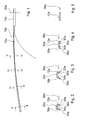
eine erfindungsgemäße Wischvorrichtung mit einem Wischarm in einer Seitenansicht,
Fig. 2
einen Schnitt entlang der Linie II-II in Fig. 1,
Fig. 3
einen Schnitt entlang der Linie III-III in Fig. 1,
Fig. 4
einen Schnitt entlang der Linie IV-IV in Fig. 1,
Fig. 5
einen Schnitt entlang der Linie V-V in Fig. 1,
Fig. 6 - 10
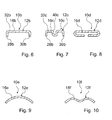
Schnittdarstellungen durch zu Fig. 1 alternativen Wischvorrichtungen,
Fig. 11
eine alternative Wischvorrichtung mit einem getrennt von einem Wischstangenbauteil ausgeführten Profilelement in einer Seitenansicht,
Fig. 12
die Wischvorrichtung aus Fig. 11 schräg von unten,
Fig. 13
einen vergrößerten Ausschnitt XIII aus Fig. 12,
Fig. 14
einen Schnitt entlang der Linie XIV-XIV in Fig. 13,
Fig. 15
einen Schnitt entlang der Linie XV-XV in Fig. 13,
Fig. 16 - 19
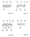
Schnittdarstellungen durch zu Fig. 11 alternativen Wischvorrichtungen,
Fig. 20
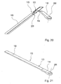
eine alternative Wischvorrichtung zu Fig. 11 mit einer Biegebereichsüberdeckung im unbelasteten Zustand schräg von unten und
Fig. 21
die Wischvorrichtung aus Fig. 20 schräg von oben im belasteten Zustand.
Beschreibung der Ausführungsbeispiele
Fig. 1 zeigt eine erfindungsgemäße Wischvorrichtung für ein Kraftfahrzeug mit einem Wischarm 10a. Der Wischarm 10a umfasst eine von einem Stanz-Biegeteil gebildete Wischstange 12a aus Federstahl und ein mit der Wischstange 12a gelenkfrei verbundenes Befestigungsteil 14a aus einem im Wesentlichen biegesteifen Stahl. Anstatt aus Federstahl könnte die Wischstange auch aus anderen, dem Fachmann als sinnvoll erscheinenden Materialien gebildet sein, wie beispielsweise aus einem glasfaserverstärkten Kunststoff usw. Die Wischstange 12a ist mittels eines so genannten Umlappens des Befestigungsteils 14a über eine Klemmverbindung im Befestigungsteil 14a befestigt. An einem dem Befestigungsteil 14a abgewandten Ende der Wischstange 12a ist im Betrieb ein nicht näher dargestelltes bügelloses Wischblatt mit einem bogenförmigen Wischleistenträger befestigt.
Erfindungsgemäß ist der Wischarm 10a im Hinblick auf einen Wischkreis, der sich um eine Lagerachse 26a des Befestigungsteils 14a erstreckt, in einem radial äußeren Bereich gegenüber einem radial inneren Bereich versteift ausgeführt, bzw. nimmt die Biegesteifigkeit der Wischstange 12a von dem dem Befestigungsteil 14a abgewandten Ende in Längsrichtung bis kurz vor das Befestigungsteil 14a kontinuierlich ab.
Die Wischstange 12a ist als Profilelement 16a ausgebildet bzw. die Wischstange 12a ist mit einem Profilelement 16a einstückig ausgeführt, das ein von einem ebenen Profil abweichendes Profil, und zwar ein zu einer zu wischenden Fläche hin offenes U-Profil aufweist. Das Profilelement 16a weist in Längsrichtung eine sich verändernde Querschnittsform auf, und zwar weisen Schenkel 28a, 30a des U-Profils ausgehend von dem dem Befestigungsteil 14a abgewandten Ende in Längsrichtung zum Befestigungsteil 14a eine abnehmende Länge auf und schließen jeweils einen von ca. 95° bis auf 180° ansteigenden Winkel 34a, 36a mit einem Bodenteil 32a des U-Profils ein (Fig. 2 bis 5). Die Schenkel 28a, 30a dienen durch ihre Schrägstellung zu einer im Betrieb auftretenden Strömungsrichtung 38a zudem jeweils als Spoilerelement, durch die im Betrieb eine zusätzliche, strömungsbedingte Auflagekraft des Wischblatts auf die zu wischende Fläche erzielt wird.
In einem Hauptbiegebereich der Wischstange 12a vor dem Befestigungsteil 14a von ca. 10 cm weist die Wischstange 12a ein im Wesentlichen parallel zur Strömungsrichtung 38a verlaufendes, ebenes Profil auf (Fig. 1 und 5). In Fig. 1 ist der Wischarm 10a in einem belasteten Betriebszustand und gestrichelt in einem unbelasteten Betriebszustand dargestellt. Im Betrieb ist die Wischstange 12a im Wesentlichen gerade ausgerichtet bzw. gerade gebogen und bewirkt dadurch eine Auflagekraft des Wischblatts auf die zu wischende Fläche.
In den Fig. 6 bis 10 sind Querschnitte durch alternative Wischvorrichtungen mit jeweils einem Wischarm 10b, 10c, 10d dargestellt. Bei den Ausführungsbeispielen sind in der Beschreibung im Wesentlichen gleiche Bauteile und gleiche Merkmale grundsätzlich mit den gleichen Bezugszeichen beziffert, wobei zur Unterscheidung der Ausführungsbeispiele Buchstaben hinzugefügt sind. Ferner kann bezüglich gleichbleibender Merkmale und Funktionen auf die Beschreibung zum Ausführungsbeispiel in den Fig. 1 bis 5 verwiesen werden. Die nachfolgende Beschreibung beschränkt sich im Wesentlichen auf die Unterschiede zum Ausführungsbeispiel in den Fig. 1 bis 5.
Der Wischarm 10b umfasst eine einstückig mit einem Profilelement 16b ausgeführte Wischstange 12b. Das Profilelement 16b weist ein U-Profil auf, dessen Schenkel 28b, 30b einen 90°-Winkel zu einem Bodenteil 32b des U-Profils einschließen. Die Schenkel 28b, 30b weisen jeweils eine Länge auf, die um ein mehrfaches kleiner ist als eine Breite der Wischstange 12b.
Der Wischarm 10c in Fig. 7 umfasst eine Wischstange 12c, an deren Bodenteil 32c gegenüber dem Bodenteil 32b in Fig. 6 zusätzlich eine nutförmige Vertiefung 40c angeformt ist. Anstatt einer einzelnen nutförmigen Vertiefung 40c sind grundsätzlich auch mehrere nutförmige Vertiefungen denkbar.
Der Wischarm 10d in Fig. 8 umfasst eine Wischstange 12d, die einstückig mit einem Profilelement 16d ausgebildet ist, das an einem einem Befestigungsteil abgewandten Ende ein relativ weit geschlossenes C-Profil aufweist, wobei das C-Profil zu einer zu wischenden Fläche hin offen ausgeführt ist. Ausgehend von dem dem Befestigungsteil abgewandten Ende in Längsrichtung zum Befestigungsteil des Wischarms 10d weist das C-Profil einen zunehmenden Öffnungsgrad auf.
Der Wischarm 10e in Fig. 9 umfasst eine Wischstange 12e, die einstückig mit einem Profilelement 16e ausgebildet ist, das ein bogenförmiges Profil aufweist, während der Wischarm 10f in Fig. 10 eine Wischstange 12f umfasst, die einstückig mit einem Profilelement 16f ausgebildet ist, das ein gewelltes Profil aufweist. Ausgehend von einem einem Befestigungsteil abgewandten Ende in Längsrichtung zum Befestigungsteil nähern sich die Profile der Profilelemente 16e, 16f einem ebenen Profil an.
In den Fig. 11 bis 15 ist eine alternative Wischvorrichtung mit einem Wischarm 10g dargestellt. Der Wischarm 10g umfasst ein Befestigungsteil 14g und eine Wischstange 12g, die von einem von einer Blattfeder aus Federstahl gebildeten Wischstangenbauteil 18g und von einem biegesteifen, aus Kunststoff extrudierten Profilelement 16g gebildet ist. Anstatt aus Kunststoff könnte das Profilelement 16g auch aus einem Metall hergestellt sein.
Das Wischstangenbauteil 18g weist ein ebenes Rechteckprofil auf und ist an einem Ende mittels eines so genannten Umlappens des Befestigungsteils 14g über eine Klemmverbindung im Befestigungsteil 14g gehalten. Mit einem zweiten Ende ist das Wischstangenbauteil 18g in einen Aufnahmebereich des Profilelements 16g eingeschoben, das im Wesentlichen ein zu einer Unterseite hin offenes C-Profil aufweist (Fig. 12 und 15).
Das Wischstangenbauteil 18g ist über eine Rastverbindung 20g im Aufnahmebereich des Profilelements 16g fixiert. Am Profilelement 16g sind an einem dem Wischstangenbauteil 18g zugewandten Ende in einer im montierten Zustand zu einer zu wischenden Fläche weisenden unteren Wandung zwei Rastmittel 22g, 22g' angeformt, die jeweils von einem kreisrunden, teilweise freigeschnittenen Abschnitt gebildet sind, der in Einschubrichtung 42g des Wischstangenbauteils 18g eine ansteigende, über eine Innenseite des Aufnahmebereichs hinausragende Schrägfläche bildet (Fig. 12, 13 und 14).
Kommt das Wischstangenbauteil 18g beim Einschieben mit seinem freien Ende in den Bereich der Rastmittel 22g, 22g', werden die Rastmittel 22g, 22g' senkrecht zur Einschubrichtung 42g und senkrecht zur Unterseite des Profilelements 16g ausgelenkt und rasten anschließend bei einer fortgeführten Einschubbewegung in von kreisrunden Durchgangsöffnungen gebildete Rastmittel 24g am Wischstangenbauteil 18g ein (Fig. 14). Anstatt dass die Rastmittel 22g, 22g' ausgelenkt werden, ist denkbar, dass das Wischstangenbauteil 18g beim Rastvorgang ausgelenkt wird. Hierfür könnten möglicherweise Freiräume an einer Deckseite des Profilelements 16g vorgesehen werden, in die das Wischstangenbauteil 18g beim Rastvorgang ausgelenkt werden bzw. ausweichen kann. Gleichzeitig mit dem Einrasten kommt das Wischstangenbauteil 18g mit seiner Stirnseite an einem in den Aufnahmebereich des Profilelements 16g ragenden, angeformten, nicht näher dargestellten Anschlag zur Anlage. Das Wischstangenbauteil 18g ist sicher im Profilelement 16g fixiert.
Das Profilelement 16g bildet im Hinblick auf einen Wischkreis einen radial äußeren, biegesteifen Teil der Wischstange 12g und das Wischstangenbauteil 18g bildet einen radial inneren Hauptbiegebereich der Wischstange 12g, der eine Länge zwischen 5 cm und 20 cm aufweist. In den Fig. 11 und 12 ist der Wischarm 10g in einem belasteten Betriebszustand dargestellt, wobei in Fig. 11 zudem der Wischarm 10g gestrichelt in einem unbelasteten Betriebszustand dargestellt ist. Im Betrieb ist das Wischstangenbauteil 18g im Wesentlichen gerade gebogen und bewirkt dadurch eine Auflagekraft eines Wischblatts auf die zu wischende Fläche.
In den Fig. 16 bis 19 sind Schnittdarstellungen durch zu Fig. 11 alternative Wischvorrichtungen dargestellt. Bezüglich gleichbleibender Merkmale und Funktionen kann auf die Beschreibung zum Ausführungsbeispiel in den Fig. 11 bis 15 verwiesen werden. Die nachfolgende Beschreibung beschränkt sich im Wesentlichen auf die Unterschiede zum Ausführungsbeispiel in den Fig. 11 bis 15.
Die Wischvorrichtung in Fig. 16 weist einen Wischarm 10h auf, der ein Befestigungsteil und eine Wischstange 12h umfasst, die von einem biegesteifen Profilelement 16h und einem von einer Blattfeder gebildeten Wischstangenbauteil 18h gebildet ist. Das Profilelement 16h weist ein geschlossenes, hülsenförmiges Profil auf.
Die Wischvorrichtung in Fig. 17 weist einen Wischarm 10i auf, der ein Befestigungsteil und eine Wischstange 12i umfasst, die von einem biegesteifen Profilelement 16i und einem von einer Blattfeder gebildeten Wischstangenbauteil 18i gebildet ist. Das Profilelement 16i weist im Wesentlichen ein zu einer Unterseite offenes C-Profil auf. Bei der Montage wird das Profilelement 16i auf eine Deckseite des Wischstangenbauteils 18i aufgesetzt und anschließend mit einer Druckbewegung senkrecht zur Deckseite des Wischstangenbauteils 18i mit seinen als Rasthaken ausgebildeten Schenkeln 44i, 46i an dem Wischstangenbauteil 18i eingerastet.
Die Wischvorrichtung in Fig. 18 weist einen Wischarm 10j auf, der ein Befestigungsteil und eine Wischstange 12j umfasst, die von einem biegesteifen Profilelement 16j und einem von einer Blattfeder gebildeten Wischstangenbauteil 18j gebildet ist.
Das Profilelement 16j weist im Wesentlichen ein aus zwei C-Profilen zusammengesetztes, zu einer Unterseite offenes Profil auf. Bei der Montage wird das Profilelement 16j auf eine Deckseite des geschlitzten Wischstangenbauteils 18j aufgesetzt und anschließend mit einer Druckbewegung senkrecht zur Deckseite des Wischstangenbauteils 18j mit seinen als Rasthaken ausgebildeten Schenkeln 44j, 46j, 48j, 50j an dem Wischstangenbauteil 18j eingerastet, wobei die Schenkel 48j, 50j in einen Schlitz des Wischstangenbauteils 18j eingreifen.
Die Wischvorrichtung in Fig. 19 weist einen Wischarm 10k auf, der ein Befestigungsteil und eine Wischstange 12k umfasst, die von einem biegesteifen Profilelement 16k und einem von einer Blattfeder gebildeten Wischstangenbauteil 18k gebildet ist. Das Profilelement 16k weist ein ebenes Rechteckprofil auf und ist auf eine Deckseite des Wischstangenbauteils 18k aufgeklebt.
In den Fig. 20 und 21 ist eine im Wesentlichen der Wischvorrichtung aus Fig. 11 bis 14 entsprechende Wischvorrichtung dargestellt. Im Gegensatz zur Wischvorrichtung in den Fig. 11 bis 14 weist die Wischvorrichtung in den Fig. 20 und 21 eine Wischstange 12l mit einem Profilelement 16l auf, das in einer Betriebsstellung ein Wischstangenbauteil 18l überlappend ausgeführt ist. Fig. 20 zeigt die Wischvorrichtung mit ihrem Wischarm 10l im unbelasteten und Fig. 21 im belasteten Zustand. Das Profilelement 16l erstreckt sich im belasteten Zustand über die gesamte Länge der Wischstange 12l.
Bezugszeichen
10
Wischarm
12
Wischstange
14
Befestigungsteil
16
Profilelement
18
Wischstangenbauteil
20
Rastverbindung
22
Rastmittel
24
Rastmittel
26
Lagerachse
28
Schenkel
30
Schenkel
32
Bodenteil
34
Winkel
36
Winkel
38
Strömungsrichtung
40
Vertiefung
42
Einschubrichtung
44
Schenkel
46
Schenkel
48
Schenkel
50
Schenkel

Claims (9)

  1. Wischvorrichtung, insbesondere für ein Kraftfahrzeug, die einen Wischarm (10a - 10l) mit zumindest einem federelastischen Teilbereich umfasst, der eine Wischstange (12a - 12l) und ein insbesondere mit der Wischstange (12a - 12l) gelenkfrei verbundenes Befestigungsteil (14a - 14l) aufweist, dadurch gekennzeichnet, dass der Wischarm (10a - 10l) im Hinblick auf einen Wischkreis wenigstens in einem radial äußeren Bereich gegenüber zumindest einem radial inneren Bereich versteift ausgeführt ist.
  2. Wischvorrichtung'nach Anspruch 1, gekennzeichnet durch ein Profilelement (16a - 16j, 16l) mit einem von einem ebenen Profil abweichenden Profil.
  3. Wischvorrichtung nach Anspruch 2, dadurch gekennzeichnet, dass das Profilelement (16a - 16l) zumindest teilweise einstückig mit der Wischstange (12a - 12l) ausgebildet ist.
  4. Wischvorrichtung nach einem der vorhergehenden Ansprüche, gekennzeichnet durch zumindest ein Profilelement (16g - 16l), das von einem zumindest zu einem Wischstangenbauteil (18g - 18l) der Wischstange (12g - 12l) getrennten Bauteil gebildet ist.
  5. Wischvorrichtung nach Anspruch 4, dadurch gekennzeichnet, dass das Wischstangenbauteil (18g - 18j, 18l) der Wischstange (12g - 12j, 12l) wenigstens teilweise in einem Aufnahmebereich des Profilelements (16g - 16j, 16l) angeordnet ist.
  6. Wischvorrichtung nach Anspruch 4 oder 5, dadurch gekennzeichnet, dass das Profilelement (16g - 16j, 16l) über wenigstens eine Rastverbindung (20g - 20j, 20l) befestigt ist.
  7. Wischvorrichtung nach einem der Ansprüche 4 bis 6, dadurch gekennzeichnet, dass das Profilelement (16l) in wenigstens einem Betriebszustand das Wischstangenbauteil (18l) zumindest teilweise überlappend ausgeführt ist.
  8. Wischvorrichtung zumindest nach Anspruch 2, dadurch gekennzeichnet, dass das Profilelement (16a - 16f) in Längsrichtung eine sich verändernde Querschnittsform aufweist.
  9. Profilelement für eine Wischvorrichtung nach einem der vorhergehenden Ansprüche zur Versteifung des Wischarms (10a - 10l) in zumindest einem Bereich.
EP04001636A 2003-02-28 2004-01-27 Wischvorrichtung Withdrawn EP1452412A1 (de)

Applications Claiming Priority (2)

Application Number Priority Date Filing Date Title
DE10308786 2003-02-28
DE2003108786 DE10308786A1 (de) 2003-02-28 2003-02-28 Wischvorrichtung

Publications (1)

Publication Number Publication Date
EP1452412A1 true EP1452412A1 (de) 2004-09-01

Family

ID=32748119

Family Applications (1)

Application Number Title Priority Date Filing Date
EP04001636A Withdrawn EP1452412A1 (de) 2003-02-28 2004-01-27 Wischvorrichtung

Country Status (2)

Country Link
EP (1) EP1452412A1 (de)
DE (1) DE10308786A1 (de)

Cited By (3)

* Cited by examiner, † Cited by third party
Publication number Priority date Publication date Assignee Title
FR2887833A1 (fr) * 2005-06-29 2007-01-05 Valeo Systemes Dessuyage Bras d'entrainement realise en materiau composite
DE102008040875A1 (de) * 2008-07-31 2010-02-04 Robert Bosch Gmbh Strangprofil sowie Verfahren zu seiner Herstellung
CN107776550A (zh) * 2016-08-24 2018-03-09 法雷奥系统公司 用于将雨刮器安装在驱动轴上的组件

Families Citing this family (2)

* Cited by examiner, † Cited by third party
Publication number Priority date Publication date Assignee Title
DE102010043301A1 (de) 2010-11-03 2012-05-03 Robert Bosch Gmbh Wischerarm für eine Scheibenwischervorrichtung
DE102011101496B4 (de) * 2011-05-14 2016-05-19 Audi Ag Airbagvorrichtung an einem Fahrzeug mit einem Scheibenairbagmodul

Citations (6)

* Cited by examiner, † Cited by third party
Publication number Priority date Publication date Assignee Title
US3685086A (en) * 1969-09-29 1972-08-22 Karl Frohlich Pressure intensifier for windshield wipers
FR2515121A1 (fr) * 1981-10-28 1983-04-29 Bosch Gmbh Robert Essuie-glace pour vehicules automobiles
WO1992022444A1 (en) * 1991-06-11 1992-12-23 Ab Volvo A device in windscreen wiper arms for motor vehicles
EP0525850A1 (de) * 1991-07-29 1993-02-03 General Motors Corporation Freitragender Wischerarm aus geformtem Verbundstoff
US6272718B1 (en) * 1998-06-08 2001-08-14 Robert Bosch Gmbh Wiper arm
EP1375273A2 (de) * 2002-06-21 2004-01-02 Robert Bosch Gmbh Scheibenwischvorrichtung

Patent Citations (6)

* Cited by examiner, † Cited by third party
Publication number Priority date Publication date Assignee Title
US3685086A (en) * 1969-09-29 1972-08-22 Karl Frohlich Pressure intensifier for windshield wipers
FR2515121A1 (fr) * 1981-10-28 1983-04-29 Bosch Gmbh Robert Essuie-glace pour vehicules automobiles
WO1992022444A1 (en) * 1991-06-11 1992-12-23 Ab Volvo A device in windscreen wiper arms for motor vehicles
EP0525850A1 (de) * 1991-07-29 1993-02-03 General Motors Corporation Freitragender Wischerarm aus geformtem Verbundstoff
US6272718B1 (en) * 1998-06-08 2001-08-14 Robert Bosch Gmbh Wiper arm
EP1375273A2 (de) * 2002-06-21 2004-01-02 Robert Bosch Gmbh Scheibenwischvorrichtung

Cited By (5)

* Cited by examiner, † Cited by third party
Publication number Priority date Publication date Assignee Title
FR2887833A1 (fr) * 2005-06-29 2007-01-05 Valeo Systemes Dessuyage Bras d'entrainement realise en materiau composite
WO2007003261A1 (fr) * 2005-06-29 2007-01-11 Valeo Systemes D'essuyage Bras d'entrainement realise en materiau composite
US7793383B2 (en) 2005-06-29 2010-09-14 Valeo Systemes D'essuyage Wiper arm made of composite material
DE102008040875A1 (de) * 2008-07-31 2010-02-04 Robert Bosch Gmbh Strangprofil sowie Verfahren zu seiner Herstellung
CN107776550A (zh) * 2016-08-24 2018-03-09 法雷奥系统公司 用于将雨刮器安装在驱动轴上的组件

Also Published As

Publication number Publication date
DE10308786A1 (de) 2004-09-09

Similar Documents

Publication Publication Date Title
DE10308785B4 (de) Wischvorrichtung
EP1278666B1 (de) Wischblatt für scheiben insbesondere von kraftfahrzeugen
EP1547884B1 (de) Wischblatt zum Reinigen von Scheiben insbesondere von Kraftfahrzeugen
EP0915785B1 (de) Wischblatt für scheiben von kraftfahrzeugen
EP1547883B1 (de) Wischblatt zum Reinigen von Fahrzeugscheiben
EP1140585B1 (de) Wischblatt für scheiben von kraftfahrzeugen
EP0869886B1 (de) Wischblatt für scheiben von kraftfahrzeugen
EP1332075B1 (de) Vorrichtung zum lösbaren, gelenkigen verbinden eines wischblatts zum reinigen von scheiben mit einem wischerarm
EP0914269B1 (de) Wischblatt für scheiben von kraftfahrzeugen
EP1322507B1 (de) Scheibenwischer
EP2271524B1 (de) Vorrichtung zum gelenkigen verbinden eines wischblatts mit einem wischarm
EP2079617B1 (de) Wischblatt
DE10207706A1 (de) Wischblatt zum Reinigen von Scheiben insbesondere von Kraftfahrzeugen
EP1695881A2 (de) Wischblatt zum Reinigen von Fahrzeugscheiben
EP1332079A1 (de) Vorrichtung zum lösbaren verbinden eines wischblatts mit einem angetriebenen wischerarm
WO2005025956A1 (de) Wischblatt
EP0923468B1 (de) Vorrichtung zum anschliessen eines wischblatts an einem wischerarm
EP1452412A1 (de) Wischvorrichtung
EP1575813B1 (de) Wischebel mit einem wischarm und einem wischblatt
EP0951410A1 (de) Wischvorrichtung für scheiben von kraftfahrzeugen mit einem langgestreckten, einendig am kraftfahrzeug geführten, angetriebenen wischerarm
EP1278665B1 (de) Gelenkteil für scheibenwischer
DE10350274B4 (de) Wischblatt zum Reinigen von Scheiben insbesondere von Kraftfahrzeugen
EP1601559B1 (de) Wischvorrichtung
DE10308781A1 (de) Wischvorrichtung
DE102006045161A1 (de) Wischleistenträger

Legal Events

Date Code Title Description
PUAI Public reference made under article 153(3) epc to a published international application that has entered the european phase

Free format text: ORIGINAL CODE: 0009012

AK Designated contracting states

Kind code of ref document: A1

Designated state(s): AT BE BG CH CY CZ DE DK EE ES FI FR GB GR HU IE IT LI LU MC NL PT RO SE SI SK TR

AX Request for extension of the european patent

Extension state: AL LT LV MK

17P Request for examination filed

Effective date: 20050301

AKX Designation fees paid

Designated state(s): DE FR GB

17Q First examination report despatched

Effective date: 20050408

RBV Designated contracting states (corrected)

Designated state(s): DE FR GB

STAA Information on the status of an ep patent application or granted ep patent

Free format text: STATUS: THE APPLICATION IS DEEMED TO BE WITHDRAWN

18D Application deemed to be withdrawn

Effective date: 20150801